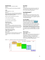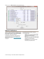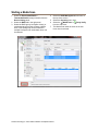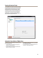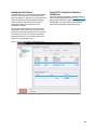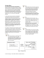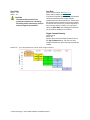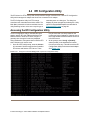
1
ATTO Utilities Installation and Operation Manual ATTO ConfigTool for Windows®, Linux® and Mac OS® X ATTO BIOS Utilities ATTO Utilities for Windows ATTO Technology, Inc. 155 CrossPoint Parkway Amherst, New York 14068 USA www.attotech.com Tel Fax (716) 691-1999 (716) 691-9353 Sales support: [email protected] Technical support: Monday -- Friday, 8am-6pm EST [email protected] (716) 691-1999 x242 © 2012 ATTO Technology, Inc. All rights reserved. All brand or product names are trademarks of their respective holders. No part of this manual may be reproduced in any form or by any means without the express written permission of ATTO Technology, Inc. 12/2012 PRMA-0267-000MD Contents 1.0 ATTO ConfigTool ...........................................................................................1 Pre-Installation Installation Using the ATTO ConfigTool Navigating the ConfigTool Driver update System Reboot 1.1 Celerity and ThunderLink FC NVRAM Settings ................................10 1.2 FastFrame NVRAM Settings ...............................................................12 1.3 ExpressPCI NVRAM Settings .............................................................13 1.4 ExpressSAS, ThunderLink SH and ThunderStream SC NVRAM Settings ..................................................................................15 1.4.1 RAID Configuration ..........................................................................17 Preliminary Steps Setting up DVRAID Customizing a RAID setup Creating a Hot Spare Pool Modifying RAID Groups Replacing a faulted drive Setup RAID Notification Using SCSI Enclosure Services (SES) Identifying Drives Selecting All Drives in the Same Enclosure Monitoring Health Monitoring S.M.A.R.T. Data Enabling or Disabling S.M.A.R.T. Monitoring Checking S.M.A.R.T. Status Filtering S.M.A.R.T. Attributes S.M.A.R.T. Notifications Test Drive Performance RAID Media Scan Feature Starting a Media Scan Media Scan Status Viewing the Scan Report Pausing or Resuming Media Scan Scheduling Media Scan Viewing Scheduled Tasks Automatic Cancellation of Media Scan Data Recovery for OFFLINE RAID Groups Definitions Failure Scenario Table Drive Replacement on a Failure Condition Recovering from Failed Drives File System Repair Tools Command Line Interface CacheAssure™ 1.4.2 SNMP Configuration ........................................................................56 Definitions Details Configuration Options Control Buttons Troubleshooting 1.5 Virtual Port Management .....................................................................63 The NPIV Panel Creating a Virtual Port Deleting a Virtual Port Troubleshooting 1.6 Troubleshoot the ATTO ConfigTool ..................................................70 2.0 BIOS Configuration Utility ..............................................................................71 Accessing the Fibre Channel utility Accessing the SCSI utility Accessing the SAS utility Common BIOS Configuration Utility functions 2.1 FC BIOS Configuration Utility ............................................................73 2.2 SCSI BIOS Configuration Utility ........................................................75 Configuring adapter channels SCSI device settings 2.3 ExpressSAS BIOS Utility ....................................................................78 Accessing the SAS utility Configuring adapter settings Displaying the drive list (ExpressSAS RAID adapter only) Configuring RAID groups (ExpressSAS RAID adapter only) 2.4 EFI Configuration Utility .....................................................................81 Accessing the EFI Configuration Utility ExpressSAS EFI Utility Configuring Adapter Settings Displaying the Drive List (ExpressSAS RAID adapter only) Configuring RAID groups (ExpressSAS RAID adapter only) Create a RAID Group 3.0 ATTO Utilities for Windows ...........................................................................92 3.1 Configure Mode Pages: Alamode Utility ...........................................93 3.2 ATTO Disk Benchmark .......................................................................94 3.3 FC LUN Masking Utility .......................................................................96 3.4 SNIA FC Storage Controller API ........................................................98 3.5 Domain Validation Testing .................................................................99 3.6 ExpressPCI SCSI Setup Utility ...........................................................101 3.7 Troubleshoot ATTO Utilities for Windows ........................................102 Appendix A CLI provides an ASCII-based interface........................................... i CLI error messages CLI summary CLI command explanations Appendix B Glossary............................................................................................. xvi 1.0 ATTO ConfigTool The ATTO ConfigTool is a utility program that displays information about installed storage controllers, drivers and devices and provides a mechanism to configure installed storage controllers in local and remote hosts. The ATTO ConfigTool is used to manage all ATTO host based products including HBAs, RAID adpaters and Desklink Devices. The ATTO ConfigTool provides a central interface for managing local and remote hosts with ATTO storage controllers installed. Features include: • The names of ATTO storage controllers installed in the host • Information about the devices attached to ATTO storage controllers • Information about the drivers and firmware controlling the storage controllers, including version information You may also use the ATTO ConfigTool to: • Update the flash image when a new version is released by ATTO • Modify the NVRAM settings (refer to the product-specific NVRAM information sections in this manual) • Manage RAID groups • Configure RAID notifications • Revert to default factory settings The factory settings should provide excellent performance for a wide range of applications. However, some applications may benefit from modification of the storage controller NVRAM settings which tune the storage controller for a specific performance range. Pre-Installation The ATTO ConfigTool is a free utility available on CD (if supplied with your storage controller) or via the ATTO website at www.attotech.com. This application supports a variety of operating systems. Please visit the ATTO website for specific operating system support information and downloads. Oracle® Java version 1.5, or later, is required to use the ATTO ConfigTool. Visit http://java.com for the latest Java updates for Linux and Windows. The latest Java runtime for Mac OS X can be obtained through Software Update. Note Note: The GNU version of the JVM does not work with the ATTO installer. You must use Oracle Java. To install the ATTO ConfigTool: • Windows - run the .exe file • OS X - mount the .dmg file • Linux - expand the .tgz file 1 ATTO Technology Inc. ATTO Utilities Installation and Operation Manual Installation The ATTO ConfigTool includes two components: a GUI Application and a system service. Either, or both, of these components can be installed on a host, depending on the functionality desired. This creates several different use cases, described below: • A host with both the GUI Application and the system service installed will be able to discover and manage local and remote hosts. This is the most comprehensive management capability. During installation of the ATTO ConfigTool select FULL installation for this coverage level. • A host with only the GUI Application installed will be able to discover and manage remote hosts. This host will not be able to discover and manage any ATTO storage controllers installed on the same host. During installation of the ATTO ConfigTool select APPLICATION ONLY for this coverage level. • A host with only the system service installed can be discovered and managed remotely, but it cannot be managed locally (the GUI Application is required for local management). It is common to have multiple hosts with only the system service installed being managed by a single host remotely. To set up a host without any local management capabilities, refer to the OS specific instructions below. Installing the ATTO ConfigTool 1 Obtain the Installer Package Download the ConfigTool package from the ATTO web-site or Copy ConfigTool package from CD. Package name is one of the following: • win_app_configtool_xxx.exe (Windows) • osx_app_configtool_xxx.dmg (OS X) • lnx_app_configtool_xxx.tgz (Linux) 2 Windows Instructions: 1 Double-click the win_app_configtool_xxx.exe package file 2 Click “Unzip” to extract the installer files 3 The files are put in “C:\ ATTO\ConfigTool” directory To install the Full Application or Application Only: 4 Navigate to the “C:\ ATTO\ConfigTool” directory 5 Double-click on the ConfigTool_xxx.exe installer executable 6 Select Full Installation or Application Only as desired 7 Follow the on-screen instructions To install the System Service only: 4 Navigate to the “C:\ATTO\ConfigTool\Service” directory 5 Double-click on the “attocfgd.msi” installer executable 6 Follow the on-screen instructions 3 OS X Instructions: 1 Double-click on the osx_app_configtool_xxx.dmg package file 2 A Finder window appears To install the Full Application or Application Only: 3 In the Finder window that appears, double-click on the ConfigTool_xxx.app installer executable 4 Select Full Installation or Application Only as desired 5 Follow the on-screen instructions To install the System Service only: 3 Navigate to the “Service” folder in the Finder window that appears 4 Double-click on the “attocfgd.mpkg” installer executable 5 Follow the on-screen instructions 4 Linux Instructions: 1 Extract the package file by running the following command in a terminal: tar -xvzf ln_app_configtool_xxx.tgz 2 Navigate to the extracted folder “ln_app_configtool_xxx” 2 To install the Full Application or Application Only: 3 Run the ConfigTool_xxx.bin installer executable as root or superuser. 4 Select Full Installation or Application Only as desired 5 Follow the on-screen instructions To install the System Service only: 3 Navigate to the “Service” directory located inside the lnx_app_configtool_xxx directory 4 Run the “attocfgd.sei” installer executable as root or superuser using the following command line: ./attocfgd.sei -i Instructions for SYSTEM SERVICE ONLY installation: 1 2 3 ATTO Technology Inc. ATTO Utilities Installation and Operation Manual Launch the ATTO ConfigTool system service Installer • Windows - Run the setup.exe in the Service folder • OS X - Run the attocfgd.mpkg file in the Service folder • Linux - Run the following command in the terminal (as root): ./attocfgd.sei -i Follow the on-screen instructions Using the ATTO ConfigTool To use the ATTO ConfigTool, locate and double-click the application icon. The main page has three windows: Device Listing, Configuration Options and Status. See Exhibit 1.0-1. The Device Listing window at the left of the display page lists local and remote hosts found on the network, as well as currently connected devices. You are required to login to manage any host. Once you login, the device tree will expand to reveal additional details on connected storage controllers. The Configuration Options window in the right window provides information and options for a device highlighted in the device listing. If you highlight a device in the Device Listing, tabs and panels display for that device. The following chart lists the tabs displayed for each device type in the device listing tree. Tree node Tabs displayed Network Host Tab Host Basic Info, Notifications, SNMP Storage Controller Basic Info, Flash, RAID, RAID CLI, Tasks Channel Basic Info, NVRAM Devices Basic Info, Flash, SES The Status window provides general information about host and storage controller settings. Exhibit 1.0-1 The ATTO ConfigTool opening page. 4 Navigating the ConfigTool CAUTION Save system data prior to installing or changing hardware configurations. Host Discovery The ATTO ConfigTool is able to discover hosts automatically, as well as manually. A host will be discovered and displayed in the Device Listing only if the system service is installed and running on the host. A host that only has the GUI Application installed will not be displayed in the Device Listing. Automatic Discovery Hosts on the local subnet are automatically discovered and placed into the Device Listing. Manual Discovery A host can be found manually by using the Network menu and selecting “Find host”. The IP address or hostname of the remote host is required. If the host is already in the Device Listing, it is not added again. Host Login Status The GUI Application must login into each host before that host can be managed or configured. The GUI Application indicates the login status for a host as follows: • A host that is not logged in will display the host icon and the text as gray and italicized. • A host that is logged in will display the host icon with a green background and black non-italicized text. • A host that was logged in but the host is rebooting will display the host icon and text as gray and italicized with a strike through. Login to a Host A login is started when the host's Device Listing tree is expanded. A login dialogue box displays and you must enter a username and password. The username and password of an administrator for the host is required to proceed, and is checked against the user credentials stored on the host. • In Windows and Mac OS X, the login information is checked against any user in the Administrators group. • In Linux, the login information is checked against the root user. If three successive login attempts fail, the GUI Application will be locked out from the host for three minutes. All login attempts that occur during the lockout period will receive an error status. GUI Applications in other hosts will not be affected by the lockout period. Once a login is established, the icon of the host is highlighted green and the text becomes black with normal font. Note There is no logout facility. Select a Host Select any host by clicking on it in the Device Listing window. The following tabs display in the Configuration Options window: • The Basic Info tab displays information about the booted operating system on that host. It also shows scheduled reboot information and provides the ability to install a driver on that host. See Exhibit 1.0-2 on page 8. • The Notification tab allows you to set up notification of certain events in the ExpressSAS RAID or ThunderStream storage controller. Refer to Setup RAID Notification on page 24 or see Exhibit 1.5.1-7 on page 26. 5 ATTO Technology Inc. ATTO Utilities Installation and Operation Manual Select a Storage Controller The following tabs display in the Configuration Options window when you select a specific storage controller in the Device Listing window. • The Basic Info tab provides basic information about the device currently highlighted in the device listing. See Exhibit 1.0-3 on page 8. • The Flash tab provides information about the current revision of flash loaded on the highlighted storage controller. See Exhibit 1.0-4 on page 9. Click on the Browse button at the bottom of the tab to search for new flash files on your host. Click on the Update button to initiate the firmware flashing process using the previously selected firmware. • The RAID tab displays information about the drive inventory, existing RAID groups and Hot Spare devices. From the RAID tab you can create, modify and delete RAID groups. See Exhibit 1.5.1--1 on page 17. • The RAID CLI tab allows experienced users to enter RAID Command Line Interface commands to the SAS RAID storage controller. • The Tasks tab displays information about tasks that are scheduled to run. In this tab, users can reschedule a task or remove the scheduled task. Select a Channel The following tabs display in the Configuration Options window when you select a specific channel in the Device Listing window: • The Basic Info tab displays PCI information for the selected channel. • The NVRAM tab displays the NVRAM parameters of the selected channel. For: • Celerity and ThunderLink FC - see Chapter 1.1 page 10 • FastFrame - see Chapter 1.2 page 12 • ExpressPCI - see Chapter 1.3 page 13 • ExpressSAS, ThunderLink SH and ThunderStream SC - see Chapter 1.4 page 15 See, also, Exhibit 1.0-5 on page 9. Note ATTO storage controllers are designed to operate properly using factory settings. Entering invalid or incorrect settings when using an NVRAM configuration utility such as the ATTO ConfigTool may cause your storage controller to function incorrectly. Select a Device The following tabs display in the Configuration Options window when you select a specific device in the Device Listing window: • The Basic Info tab displays information about the selected device. • The Flash tab provides a tool to update the firmware of the selected device. The flash tool is only available for devices that support flash update. • The SES tab displays SES (SCSI Enclosure Services) status information, such as power supplies and fans, for SES devices. About panel The About panel, selected from the About menu item in the Help menu, is an informational page which displays a list of components installed for the ATTO ConfigTool, the tool's version number and ATTO Technology contact information. 6 Driver update A storage controller driver can be installed or upgraded on a host by going to the Basic Info tab for that host, choosing a driver package in the driver update section and clicking update. The driver package is the .exe (Windows), .tgz (Linux) or .dmg (Mac OS X) file available on the ATTO product CD or downloaded from the ATTO website. If a reboot is required, the GUI will prompt once the install completes. If a driver was installed that has no matching storage controller, the GUI will prompt to shutdown and install the storage controller. Note It is important to keep firmware and drivers up-to-date for optimal performance. Refer to the product release notes (PRNs) on the ATTO web site download page for additional information. System Reboot A host can be rebooted using its Basic info tab. Select “Restart” and optionally provide a message. The host will reboot in 30 seconds for Windows or in one minute for Linux and OS X. The Message area will be updated to reflect the fact that the host has a scheduled reboot and display the time the reboot will occur. Once a reboot is scheduled, another reboot cannot be scheduled. On Linux and OS X, pressing the Refresh button detects any scheduled reboot and displays the reboot information on the Basic Info tab. On Windows systems there is no way to detect a scheduled reboot. If the GUI Application attempts to schedule a reboot and there is already one scheduled, the GUI Application will display an error status and the GUI Application is now aware that a scheduled reboot is active. A scheduled reboot can be cancelled using the Cancel button. The host that is scheduled to reboot displays on its console a pop-up message that indicates the system will be rebooting. The format of the pop-up message is dependent upon the operating system. 7 ATTO Technology Inc. ATTO Utilities Installation and Operation Manual Exhibit 1.0-2 The Basic Info tab when you choose a Host from the Device Listing. Exhibit 1.0-3 The Basic Info tab when a storage controller is chosen from the Device Listing. 8 Exhibit 1.0-4 The Flash tab. Exhibit 1.0-5 The NVRAM information page. 9 ATTO Technology Inc. ATTO Utilities Installation and Operation Manual 1.1 Celerity and ThunderLink FC NVRAM Settings The settings in the NVRAM tab vary depending upon the selected Celerity or ThunderLink Fibre Channel storage controller and the operating system. Settings unsupported by that OS are not displayed. ATTO storage controllers are designed to operate properly using factory settings. Entering invalid or incorrect settings when using an NVRAM configuration utility such as the ATTO ConfigTool may cause your storage controller to function incorrectly. CAUTION Back up system data when installing or changing hardware configurations. Use caution when making changes to NVRAM settings and only make changes to those with which you are familiar. Once you have made the desired changes, click Commit to save the changes. Changes do not take effect until you reboot the system. If you do not want to make any changes, you may choose one of the following: • Defaults: restores the storage controller to factory default settings. The Commit button must be clicked to save any changes. • Restore: reverts to the NVRAM settings saved the last time the Commit button was used. Clicking Commit is not necessary. Node Name The Node WWN assigned to this channel of the storage controller. Port Name The Port WWN assigned to this channel of the storage controller. Boot Driver Choices: enabled, scan only, disabled Default: disabled If enabled and disk drives or a bootable CD are detected during the bus scan, the BIOS driver remains resident. If disabled, the BIOS starts, resets the storage controller chip and unloads the driver. If Scan Only is selected, the BIOS driver scans the bus and displays the devices attached, then unloads itself after a brief delay. Hard Address Enable Button Choices: enabled, disabled Default: disabled When a Fibre Channel loop is initialized, each device selects and configures itself to an available ID. Hard Address Enable permits the host to select the value entered in the Hard Address field. Hard Address Choices: None, 0-125 Default: 0 The value used as the FC-AL hard address. A value to represent the address if hard addressing is enabled. Execution Throttle Choices: 1- 255 Default: 32 Specifies the maximum number of concurrent commands which can be achieved per port or per LUN. Increasing this value may increase performance, but too many concurrent commands can saturate a drive, ultimately decreasing performance. Note This is only honored by the StorPort version of the Windows driver. 8 Gig requires version 1.10 or later, while 4 Gig requires 2.64 or later. Frame Size Choices: 512, 1024, 2048 Default: 2048 Changes the size of the FC packet of information being sent. Typically, the initiator and target negotiates the desired frame size, starting with the largest value. The frame size should be set to the largest value for normal operation. Device Discovery Choices: Node WWN, Port WWN Default: Port WWN Specifies the type of device discovery the storage controller performs. Use the Port WWN when the storage controller requires separate paths to a device and the device is dual ported. A dual ported device has one path when the Node WWN is specified and two paths when the Port WWN is specified. 10 Connection Mode Options Link Down Timeout Choices: AL, PTP, AL Preferred, PTP Preferred Default: PTP Preferred Choices: 0-255 Default: 0 • The number of seconds the driver waits for a link that is down to come up before reporting it to the operating system. • • • Arbitrated Loop (AL): Connects to either an Arbitrated Loop or a Fabric Loop Port (FL Port) on a switch. Point-to-Point (PTP): Connects to a direct Fabric connection, such as an F port on a switch. AL Preferred: Allows the card to determine what kind of connection to use, but tries to connect in Loop mode first, then Point-to-Point mode. PTP Preferred: Allows the card to determine what kind of connection is to use, but tries to connect in Point-to-Point mode first, then Loop mode. Note Not all driver versions support this on 4 Gig Celerity. This feature requires 2.63 or later on Windows and Linux, and 3.25 or later on OS X. All versions of the 8 Gig driver support this. Spinup Delay Data Rate Choices: 0-255 Default: 0 Choices for 4 Gig: 1 Gb/sec., 2 Gb/sec., 4Gb/sec., Auto Choices for 8 Gig: 2 Gb/sec., 4Gb/sec., 8Gb/sec., Auto Default: Auto Specifies number of seconds the driver waits for the first device to be logged in and become ready. Selects the Fibre Channel transmission rate. Auto indicates that the storage controller determines the rate based upon the devices connected. Interrupt Coalesce Choices: None, Low, Medium, High Default: (pre 3.20) Low, (3.20 and higher) None Specifies the time period an storage controller chip delays an interrupt. This allows the storage controller chip to queue up more than one interrupt before interrupting the CPU. When this methodology is chosen there is less overhead to service the interrupts. However, the coalescing time may delay the delivery of the completion for a single interrupt. Port Down Retry Count Choices: 0-255 Default: 8 The number of times the driver retries a command to a port which is currently logged out. Note Not all driver versions support this on 4 Gig Celerity. This feature requires 2.63 or later on Windows and Linux, and 3.25 or later on OS X. All versions of the 8 Gig driver support this. Note This is only honored by the Celerity BIOS driver in 3.20 and later. PCI Memory Write/Invalidate Button (PCI-X models only) Choices: Default, disabled Default: Default The hosts BIOS setting is overwritten and the PCI memory write/invalidate setting is disabled. PCI Latency Timer (PCI-X models only) Choices: 8, 16, 24, 32, 40, 48, 56, 64, 80, 96, 112, 128, 160, 192, 224, 248 Default: see below Specifies how long the storage controller maintains control of the PCI bus. Larger values allow the storage controller to remain on the bus longer, improving performance, especially for large files. However, controlling the PCI bus for too long can starve IO to other devices, adversley affecting their performance.As a default, the computer system firmware/BIOS automatically sets this vaule. However, adjusting the value for the ATTO storage controller overrides the system default, allowing you to achieve specific performance results. 11 ATTO Technology Inc. ATTO Utilities Installation and Operation Manual 1.2 FastFrame NVRAM Settings The settings in the NVRAM tab vary depending upon the selected adapter and the operating system. Settings unsupported by that OS are not displayed. ATTO storage controllers are designed to operate properly using factory settings. Entering invalid or incorrect settings when using an NVRAM configuration utility such as the ATTO ConfigTool may cause your storage controller to function incorrectly. CAUTION Back up system data when installing or changing hardware configurations. Use caution when making changes to NVRAM settings and only make changes to those with which you are familiar. Once you have made the desired changes, click Commit to save the changes. Changes do not take effect until you reboot the system. If you do not want to make any changes, you may choose one of the following: • Defaults: restores the storage controller to factory default settings. The Commit button must be clicked to save any changes. • Restore: reverts to the NVRAM settings saved the last time the Commit button was used. Clicking Commit is not necessary. Boot Driver (currently not available, future support) Choices: enabled, scan only, disabled Default: disabled If enabled and disk drives or a bootable CD are detected during the bus scan, the BIOS driver remains resident. If disabled, the BIOS starts, resets the storage controller chip and unloads the driver. FIP VLAN Discovery Choices: enabled, disabled Default: enabled Specifies whether the storage controller should attempt to use the FCoE Initialization Protocol (FIP) to discover configured VLANs. Frame Size Choices: 512, 1024, 2048 Default: 2048 Changes the size of the FC packet of information being sent. Typically, the initiator and target negotiates the desired frame size, starting with the largest value. The frame size should be set to the largest value for normal operation. Device Discovery Choices: Node WWN, Port WWN Default: Port WWN Specifies the type of device discovery the storage controller performs. Use the Port WWN when the storage controller requires separate paths to a device and the device is dual ported. A dual ported device has one path when the Node WWN is specified and two paths when the Port WWN is specified. Interrupt Coalesce Choices: None, Low, Medium, High Default: Low If Scan Only is selected, the BIOS driver scans the bus and displays the devices attached, then unloads itself after a brief delay. Specifies the time period a storage controller chip delays an interrupt. This allows the storage controller chip to queue up more than one interrupt before interrupting the CPU. When this methodology is chosen there is less overhead to service the interrupts. However, the coalescing time may delay the delivery of the completion for a single interrupt. FCoE LLI LLI Moderation Choices: enabled, disabled Default: enabled Specifies whether to enable Low Latency Interrupts (LLI) for FCoE traffic. This prioritizes the processing of FCoE frames but may result in excessive interrupts. Choices: Disabled, Low, Medium, High Default: Low Specifies the time period an storage controller chip delays a Low Latency Interrupt (LLI) for FCoE traffic. This is the equivalent of the Interrupt Moderation setting for low-latency FCoE frames. 12 1.3 ExpressPCI NVRAM Settings The settings in the NVRAM tab vary depending upon the selected storage controller and the operating system. ATTO storage controllers are designed to operate properly using factory settings. Entering invalid or incorrect settings when using an NVRAM configuration utility such as the ATTO ConfigTool may cause your storage controller to function incorrectly. CAUTION Back up system data when installing or changing hardware configurations. Use caution when making changes to NVRAM settings and only make changes to those with which you are familiar. Once you have made the desired changes, click Commit to save the changes. Changes do not take effect until you reboot the system. If you do not want to make any changes, you may choose one of the following • Defaults: restores the storage controller to factory default settings. The Commit button must be clicked to save any changes. • Restore: reverts to the NVRAM settings saved the last time the Commit button was used. Clicking Commit is not necessary. The upper part of the NVRAM Config panel contains common NVRAM settings which pertain to the entire channel. The lower part contains settings which can be set for each SCSI ID on the channel. Controller ID Choices: 0-15 Default: 7 The ExpressPCI SCSI storage controller is normally set to SCSI ID 7 because ID 7 has the highest priority on the bus. The setting should remain at ID 7 unless you are instructed to change it by an ATTO Technical Support representative. Termination Choices: Auto, High Default: Auto Set to Automatic unless there is a narrow SCSI cable connected to either the internal or external connector. Selection Timeout (ms) Choices: 1ms - 1 sec. Default: 250 ms Specifies the amount of time a device has to respond to being selected. The time value can be lowered to speed up the boot process. If the value is lower than the recommended 250 ms, some devices may not have enough time to respond. Fallback Sync Rate (MB/sec.) Choices: 40/20, 20/10 and 10/5 Default: 40/20 Specifies the maximum synchronous transfer rate to be negotiated when the storage controller detects a SingleEnded SCSI bus. The bus is Single-Ended when UltraSCSI devices are connected to the bus. Bus Reset Delay (sec.) Read only; no choices Default: 3 Sets the time delay between the reset of the SCSI bus and the scanning of the SCSI bus. This is a read only parameter. Quick Arbitrate & Select Choices: disabled, enabled Default: enabled If enabled, improves performance by reducing the time required to gain control of the SCSI bus. QAS can only be enabled if all target settings are set to Sync DT-IU and all devices on the bus support QAS. Wide IDs Choices: enabled (targets 0-15), disabled (targets 0-7) Default: enabled This setting is available only in Mac OS X and for Ultra160 or Ultra/WIDE ExpressPCI storage controllers. Boot Driver Choices: enabled, scan only, disabled Default: enabled If enabled and disk drives or a bootable CD are detected during the bus scan, the BIOS driver remains resident. If disabled, the BIOS starts, resets the storage controller chip and unloads the driver. If Scan Only is selected, the BIOS driver scans the bus and displays the devices attached, then unloads itself after a brief delay. 13 ATTO Technology Inc. ATTO Utilities Installation and Operation Manual Specified Target Sync Offset Choices: 0 to 15 or 0 to 7 if Wide ID is disabled Default: 0 Choices: 0-127 Default: 127 Specifies the target ID to which settings are applied. LUNs The defaults offer the best performance possible. The value should not be changed unless instructed by an ATTO Technical Support representative. Choices: Disable ID, 0, 0-7, 0-63 Default: 0-7 Sync Enabled for this ID Specifies the number of LUNs which the driver addresses when scanning for devices, determined as follows. This setting is not available in Mac OS X. Disable ID: Target ID is bypassed and not scanned 0: Scan LUN 0 for this target ID 0-7: Scan LUNs 0 to 7 for this target ID Choices: enabled, disabled Default: enabled Specifies whether the selected target transfers data at synchronous transfer rates or at the asynchronous rate. The maximum synchronous rate to negotiate is specified in the Sync Rate parameter. Sync Rate (MB/s) 0-63: Scan LUNs 0 to 63 for this target ID Choices: varies by storage controller, see Exhibit 1.3-1 Default: varies by storage controller, see Exhibit 1.3-1 Allow Disconnect Tagged Command Queuing If synchronous transfers are enabled, the sync rate specifies the maximum rate at which the ExpressPCI storage controller negotiates with the selected target ID. Set the rate to the maximum value supported by the storage controller. If excessive SCSI errors occur, if you have long cables or if there are many devices on the bus, you may want to reduce the Sync Rate value. Slowing the transfer rate may increase the reliability of the SCSI bus. Choices: enabled, disabled Default: enabled Wide Transfers Choices: enabled, disabled Default: enabled Specifies if a device is allowed to disconnect from the SCSI bus during SCSI command processing. The device determines when it disconnects. This setting does not force the device to disconnect. Specifies to the driver if SCSI commands can use the Tag Command feature to send multiple commands to a device. Choices: disabled, enabled Default: enabled Specifies if the initiator negotiates wide data transfers. If the parameter is disabled, narrow data transfers are negotiated. Wide Transfers is automatically set to enabled when the Sync Rate specifies a DT rate. The DT sync rates must have wide data transfers. Exhibit 1.3-1 Possible sync rates for various ATTO storage controllers. 14 1.4 ExpressSAS, ThunderLink SH and ThunderStream SC NVRAM Settings The settings in the NVRAM tab vary depending upon the selected storage controller and the operating system. ATTO storage controllers are designed to operate properly using factory settings. Entering invalid or incorrect settings when using an NVRAM configuration utility such as the ATTO ConfigTool may cause your storage controller to function incorrectly. CAUTION Back up system data when installing or changing hardware configurations. Heartbeat Choices: enabled, disabled Default: enabled When enabled, requires the firmware to respond to periodic activity. If the firmware does not respond, the system driver resets the firmware on the storage controller. NCQ Use caution when making changes to NVRAM settings and only make changes to those with which you are familiar. Once you have made the desired changes, click Commit to save the changes. Changes do not take effect until you reboot the system. If you do not want to make any changes, you may choose one of the following: • Defaults: restores the storage controller to factory default settings. The Commit button must be clicked to save any changes. • Restore: reverts to the NVRAM settings saved the last time the Commit button was used. Clicking Commit is not necessary. Choices: enabled, disabled Default: enabled SAS Address Read only Specifies the number of seconds which the driver waits for devices to appear. Displays the SAS address assigned to the storage controller. The value cannot be modified. Device Wait Count Boot Driver Choices: enabled, scan only, disabled Default: enabled If enabled and disk drives are detected during the bus scan, the BIOS driver remains resident. If disabled, the BIOS starts, resets the storage controller chip and unloads the driver. If Scan Only is selected, the BIOS driver scans the bus and displays the devices attached, then unloads itself after a brief delay. When enabled, the storage controller driver sends multiple simultaneous commands to NCQ capable SATA disk drvies. Phy Speed (6Gb SAS/SATA storage controllers only) Choices: Auto, 6Gb/s, 3Gb/s, 1.5 Gb/s Default: Auto Allows the user to manually adjust the speed of the PHY. Drive Wait Time Choices: 1-255 seconds Default: 3 Choices: 1-255 devices Default: 1 Specifies the number of devices which must appear in order to cancel the Drive Wait Time period. LED Control (R608, R60F, H608 & H60F only) Choices: SGPIO, I2C, Disabled (H6XX only) Default: SGPIO for R6XX, disabled for H6XX Specifies the method used to perform LED control. The storage controller exposes a virtual SES device that provides standard SCSI SES commands for LED control. The standard SCSI commands can control the locate and failure LED. The virtual SES driver will use the specified method to send the commands to the drive backplane. See the ExpressSAS installation manual for instructions to connect cables for SGPIO or I2C LED control. 15 ATTO Technology Inc. ATTO Utilities Installation and Operation Manual Spinup Delay Multiplexing (6Gb RAID storage controllers only) Choices: 0-20 seconds Default: 0 Choices: enabled, disabled Default: disabled Specifies the number of seconds each SAS PHY waits for disk drives to spin up. When enabled, it allows multiple 3Gb devices to aggregate 6Gb SAS bandwidth. In order to utlilize this feature, devices must support Multiplexing and conform to SAS 2.0 compliancy. 16 1.4.1 RAID Configuration ExpressSAS RAID and ThunderStream SC storage controllers provides the capability to configure disk storage into RAID groups or Hot Spare drives. Use the ATTO ConfigTool to set up RAID groups on your ExpressSAS RAID or ThunderStream SC storage controller in one of the following RAID levels: • JBOD • RAID Level 0 • RAID Level 1 • RAID Level 4 • RAID Level 5 • RAID Level 6 • RAID Level 10 • ATTO DVRAID™ (parity redundancy optimized for digital video environments: refer to Setting up DVRAID on page 18). ATTO DVRAID is set up automatically by the ExpressSAS RAID or ThunderStream SC storage controller firmware. All other types of RAID require customized input.See Exhibit 1.4.1-1. Each RAID group may be divided into one or more partitions; each partition appears to the host operating system as a virtual disk. You may use the RAID Command Line Interface page from the RAID CLI tab in the ATTO ConfigTool to set up or modify various parameters (Refer to Appendix A). However, the ATTO ConfigTool procedures listed in this chapter are the preferred procedures for setting up RAID configurations for ExpressSAS RAID and ThunderStream SC storage controllers. Note The ConfigTool screens are similar for all operating systems. Exhibit 1.4.1-1 ConfigTool RAID page. 17 ATTO Technology Inc. ATTO Utilities Installation and Operation Manual Preliminary Steps 1 2 3 4 5 Locate the ConfigTool icon in the folder you created during installation (Refer to ATTO ConfigTool on page 1). Double-click on the icon to start the application. The Welcome screen appears. From the left-hand panel Device Listing, expand all the elements of the selected hosts in the Network tree. Click on ExpressSAS R6XX or ThunderStream SC 3808. 6 A new set of tabs appears in the right panel. Click on the RAID tab. 7 The application scans for drives. A list of drives appears. Devices are displayed in the top panel and RAID groups and Hot Spares are displayed in the bottom panel. If you have not yet defined any RAID groups, selecting the RAID tab automatically starts a RAID wizard. The wizard is displayed in the bottom panel. If the RAID wizard does not start automatically, select the RAID Management menu item at the top of the screen, then select the Create RAID Group from the menu presented. Select either Setup DVRAID (continue with Setting up DVRAID on page 18) or Custom RAID setup (continue with Customizing a RAID setup on page 19). 8 Setting up DVRAID DVRAID (Digital Video RAID) provides parity redundancy for your data. Optimized for performance for the high data transfer rates required in digital video environments, DVRAID is ATTO Technology proprietary technology which supports the editing of uncompressed 10-bit High Definition (HD) video and multiple streams of real-time, uncompressed Standard Definition (SD) video. The DVRAID wizard automatically sets up DVRAID using all storage attached to the ExpressSAS RAID or ThunderStream SC storage controller based on the number of available drives. See Exhibit 1.4.1--2. DVRAID setup cannot be used if any other RAID groups are present. 18 Exhibit 1.4.1--2 The DVRAID wizard automatically sets up the number of RAID groups based on the number of available drives. Each RAID group uses one drive as a parity drive. Available drives RAID groups created Drives in each group 6 7 8 12 14 16 24 1 1 1 2 2 2 4 6 7 8 6 7 8 6 If you do not have 6, 7, 8, 12, 14, 16 or 24 drives, you cannot use the DVRAID wizard. If you do not want all storage set up in DVRAID or you do not have the correct number of drives, use Customizing a RAID setup. 5 1 6 2 3 4 After following Preliminary Steps on page 18, select the DVRAID radio button in the ConfigTool RAID wizard. Click on OK. The ExpressSAS RAID and ThunderStream SC storage controller firmware automatically uses all unassigned disks to create a DVRAID configuration. A confirmation dialog box asks you to confirm the configuration you have chosen. Click Yes. A message box displays while the RAID group is being created. When the RAID group is complete, the lower panel displays the RAID group(s). The DVRAID group begins to rebuild. Double click on your RAID group in the lower panel to see more detail such as the status of the rebuild. Wait until the rebuild is complete before sending data to the storage. Note A RAID rebuild may take several hours to complete. 7 Click on OK. 3 4 Advanced initialization is recommended for new drives because the procedure erases and verifies the drive media. The RAID group is unavailable until initialization is complete. Express initialization performs RAID group setup in the background and the RAID group is immediately available for use. Click Next. Select the disk devices in the top panel and drag them into the device area in the bottom panel. See Exhibit 1.5.1--4 on page 21. If you want the RAID group to be presented as one virtual disk (partition) with the default RAID group properties, click Finish. If you want to change other parameters from default values, click Next and select the desired property. Customizing a RAID setup 1 2 After following Preliminary Steps on page 18, select the Custom RAID radio button. See Exhibit 1.4.1-1 on page 17. Select the options to configure the new RAID group (see Exhibit 1.5.1--3 on page 21): • RAID Group Name: Assign a name to the RAID group. The name must be unique and no more than 14 characters. • RAID Group Level: Select a RAID group level from the drop-down box. • RAID Group Interleave: Select an interleave value. The default value is 128KB. • RAID Group Mirror Count: Select a mirror count, a copy of the original data stored on a separate disk, for RAID groups that have mirrors. • Initialize: Select the initialization method for the RAID group. The default is Advanced. 5 19 ATTO Technology Inc. ATTO Utilities Installation and Operation Manual • 6 SpeedRead, Auto-Rebuild and Rebuild Priority: refer to Change RAID group properties on page 23 for specific information on these parameters. • Sector Size: specifies the sector size that each partition (virtual disk) within the RAID group presents to the host system. The sector size can be set to 512 bytes (default) or 4096 bytes. This parameter can only be set during RAID group creation. The available size is determined by the sector sizes of the physical disks selected for the RAID group. If the sector size for the physical disks is 512 bytes, then either 512 or 4096 is valid. If the sector size of the physical disks is 4096 bytes, then 4096 is the only valid value for this property. The selection of a sector size of 4096 bytes provides the capability to create a 16TB virtual disk that is supported on Windows XP 32-bit version. If you want more than one virtual disk (partition) click Next and select one of the following: • leave as one partition • partition by count • partition by size When you have made all your selections, click Finish. 7 A confirmation dialogue box asks you to confirm the configuration you have chosen. Click Yes. 8 The RAID group configuration you have chosen is initialized and completed. The time it takes to initialize the RAID configuration you have chosen depends on the RAID level selected, the capacity of the drives and the initialization method selected. 20 Exhibit 1.4.1--3 Selecting the options to configure the new RAID group. Exhibit 1.4.1--4 Selecting drives for a new RAID group. 21 ATTO Technology Inc. ATTO Utilities Installation and Operation Manual Creating a Hot Spare Pool If a member of a RAID group becomes degraded or fails, you lose some redundancy in your RAID group until a new member is rebuilt into the RAID group. You can set up a Hot Spare Pool with drives of different sizes which are designated as replacements for faulted devices at any time, either before or after creating RAID groups. A degraded RAID group is automatically rebuilt if a suitable disk is available in the Hot Spare Pool. 1 After following the Preliminary Steps on page 18, find the Hot Spare tab in the bottom panel within the RAID tab. 2 Select the Hot Spare tab to show existing members of the Hot Spare Pool. 3 To add drives to the Hot Spare Pool, select unallocated drives from the top panel and drag them to the Hot Spare Pool. To remove a drive from the Hot Spare Pool, select the drive, click on it and click on Delete Hot Spares. Note An unallocated drive or unallocated storage is storage which is not part of a RAID group, not already designated as a Hot Spare or was offline when you set up a RAID group using the ATTO ConfigTool. Modifying RAID Groups The ATTO ConfigTool interface may be used to replace a failed drive, add capacity to a RAID group, or change a RAID configuration from the current configuration to a new configuration. CAUTION Data can be compromised or lost when deleting storage or rearranging storage configurations. The ATTO ConfigTool interface takes you step by step through many procedures which allow you to modify your storage and RAID configurations. Read all notes and cautions carefully as you go to ensure the best performance and use of your storage. Many of these procedures are only available using unallocated storage. Begin each process by following the Preliminary Steps on page 18 and clicking on the desired process in the RAID Management menu. Note An unallocated drive or unallocated storage is storage which is not part of a RAID group, not designated as a Hot Spare or was offline when you set up a RAID group using the ATTO ConfigTool. Expand capacity Click on Expand Capacity in the RAID Management menu and follow the on-screen instructions. Depending on the RAID configuration, you may need to add more than one device. CAUTION Adding drives to an existing RAID group may adversely impact performance. You cannot reverse this operation unless you delete the RAID group. Change from one RAID level to a new RAID Level Changing from one RAID level to another RAID level is called migration. The following migration levels are supported: • JBOD to RAID Level 0 • JBOD to RAID Level 1 • RAID Level 0 to RAID Level 10 • RAID Level 1 to RAID Level 10 Select Migrate RAID in the RAID Management menu and follow the on-screen instructions. Delete a RAID group To delete a RAID group using the ATTO ConfigTool, click on Delete Group in the RAID Management menu and follow the on-screen instructions. CAUTION Data can be compromised or lost when deleting storage or rearranging storage configurations. 22 Change RAID group properties A RAID group has properties that are specific to the RAID group. The value of each property remains with the RAID group when it is moved from one computer to another. Some of the properties can only be specified during RAID group creation whereas others may be changed at any time during the life of the RAID group. 1 2 3 Select a RAID group in the Groups panel. Click on Properties in the RAID Management menu. View or change the current properties. • SpeedRead specifies the cache policy to be used during read operations. Once a read command is given, the SAS/SATA RAID 4 storage controller retrieves the next set of sequential data from the RAID group and caches it in internal memory. If you select Never, read caching is never performed. If you select Always, read caching is always performed. If you select Adaptive, the default, SpeedRead is enabled or disabled depending on the sequential patterns detected in I/O requests. • Auto-Rebuild controls the replacement of a faulted drive with any available unallocated drive. When you click on the Auto-Rebuild check box and the Accept button, AutoRebuild is enabled. If a drive becomes faulted, the SAS/SATA RAID storage controller replaces the drive with an unallocated drive. • Rebuild Priority specifies the ratio of rebuild I/O activity to host I/O activity. A rebuild priority of Same (default value) indicates that rebuild I/O and host I/O are treated equally. A rebuild priority of low indicates that host I/O is given a higher priority than rebuild I/O. A rebuild priority of High indicates that rebuild I/O is given a higher priority than host I/O. • Prefetch specifies the number of stripes that are read when SpeedRead is enabled or adaptive. The valid values for Prefetch are 0, 1, 2, 3, 4, 5 and 6, and the default value is 1. This property can only be changed after the RAID group is created. To access this property, select the RAID group and view its properties. Click Accept. Replacing a faulted drive If a drive in a RAID group fails, the RAID group’s status becomes degraded. To return to optimal functionality, replace the faulted drive using one of the following mechanisms. Note All of these mechanisms start a RAID group rebuild after the drive is replaced. A RAID group rebuild may take several hours to complete. The RAID group is accessible during rebuild; however, performance may be impacted, depending on the Rebuild Priority assigned. Create a Hot Spare Pool A faulted drive is automatically replaced if a suitable disk is available in the Hot Spare Pool. You set up a Hot Spare Pool with drives reserved until a RAID group member fails; they are not available when creating a RAID group. Refer to Creating a Hot Spare Pool on page 22. 23 ATTO Technology Inc. ATTO Utilities Installation and Operation Manual Enable Auto-Rebuild Manually replace a drive A faulted drive is automatically replaced if AutoRebuild is enabled and a suitable unallocated disk is available. Suitable unallocated drives are initialized, large enough to replace the degraded drive, and cannot contain any RAID group information. The unallocated drive may be a pre-existing drive or a newly-seated drive. If a Hot Spare Pool exists, the SAS/SATA RAID storage controller chooses a suitable Hot Spare drive before selecting an unallocated drive. Refer to Change RAID group properties on page 23. You may replace a drive and rebuild a RAID group manually. 1 2 After following the Preliminary Steps on page 18, double-click on the degraded RAID group in the bottom panel. A RAID group members tab displays in the bottom panel. Select an unallocated drive from the drive inventory and drag it over the degraded drive in the members tab. If the selected drive is appropriate, the faulted drive is replaced. Setup RAID Notification The ATTO ConfigTool provides a mechanism to issue a notification when a RAID event occurs in ExpressSAS RAID or ThunderStream SC storage controllers. RAID events are divided into three categories: • Critical events indicate a serious problem has occurred and the administrator of the RAID group should perform corrective action. • Warning events are less serious but still warrant notification. • Information alerts provide additional useful information about warnings or critical events. The Notifications tab provides numerous drop-down boxes that allow for the selection of the types of RAID events to receive for a notification. There are four options available in these drop-down boxes: • Critical: Only RAID events of a Critical level are reported for the notification. • Warning: Only RAID events of Warning and Critical level are reported for the notification. • All: All RAID events (Information, Warning, Critical) are reported for the notification. • None: No RAID events are reported for the notification. This level is particularly useful if a notification feature is not desired. The notifications are specified at the host system level and apply to all ATTO SAS/SATA RAID storage controllers installed in the host system. Basic alerts The Basic Alerts section of the Notifications tab provides the controls to select the levels of RAID events for Audible and Visual notifications, as well as the level of RAID events to output to the system event log. Audible Alerts utilize the system speaker and/or the hardware buzzer on a R6xx adapter to produce the notification. When triggered, the alarm continuously sounds until it is stopped by the user. There is an icon in the system tray (or system status area) that is used to turn off the alarm. The user must right-click on the icon and then select Mute Audible Alert from the menu. This will stop the alarm. The system tray icon also provides a control that will allow the user to enable/disable the hardware buzzer, so that only the alert via the system speaker is used. This allows the hardware buzzer to be turned off independently of the system speaker. It can also serve a remote purpose. If the daemon is on a server in a server room, the sysadmin can click the control to disable it. The hardware buzzer is enabled by default. Note Audible alerts may not be available on your operating system. Visual Alert utilize pop-up message boxes to display the contents of a RAID event. The pop-up may be closed using the pop-ups button. 24 Logging The ATTO ConfigTool Service outputs RAID events and other useful informational messages to the system event log. The level of RAID events inserted into the system event log may be controlled by the System Log drop-down box in the Basic Alerts section of the Notifications tab. See Exhibit 1.5.1--5 The ConfigTool also generates a log on a per-adapter basis, as well as one for the SNMP functionality and the daemon itself. These are collected with the onebutton diagnostics menu item. This can be useful when contacting ATTO Technical Support. Choose Help, Run Diagnostics, then choose a place to save the file output. It may take several minutes to gather the log. See Exhibit 1.5.1--6 Exhibit 1.4.1--5 The Basic Alerts controls of the Notifications tab in the ATTO ConfigTool. Exhibit 1.4.1--6 Run Diagnostics generates an extensive log to aide in troubleshooting. of RAID event via the drop-down box displayed next to each email address text field. The ATTO ConfigTool Service can be configured to use a TLS/SSL email server (eg. Gmail™, Yahoo®, etc.) as well as the port to use when connecting to the email server. The ATTO ConfigTool Service's connection to the email server may be configured using the following controls: • Server Address: specifies the address of the SMTP email server to use when sending an email (eg. smtp.example.com) • Sender Address: specifies the text that will show in the “From” field in the sent email. This may contain an actual email address, or any other text that may be useful in identifying the sent email (eg. [email protected], server123, etc.) • Username: specifies the username or login ID that is required when logging into the email server to send an email • Password: specifies the password for the account identified by the Username. • Enable SSL: when checked, the ATTO ConfigTool Service will attempt to connect to the email server using the SSL protocol.When unchecked, the ATTO ConfigTool Service will attempt to connect to the email server using an unsecured channel. • Port: specifies the port number to which the ATTO ConfigTool Service attempts to connect to the email server. Valid values are 1-65535. Note Contact your email provider for the appropriate Port number. Using any other number will result in an email notification failure. Email The ATTO ConfigTool Service periodically sends email notifications to the designated email address(es) that have been input under the Notification Addresses: field(s). There are three text fields under which email addresses can be specified, and more than one email address may be specified in each text field, as long as they are separated by a comma. Each email address text field can be configured to receive a specific level Email notifications are sent at 15-minute intervals. If a Critical RAID event is detected, an email notification will be sent after a 10-second delay. This delay allows the ATTO ConfigTool Service to gather supporting RAID events that may be useful in identifying why the Critical RAID event occurred. 25 ATTO Technology Inc. ATTO Utilities Installation and Operation Manual Exhibit 1.4.1--7 The Notifications tab in the ATTO ConfigTool. Exhibit 1.4.1--8 Mute Audible Alert (Windows) Exhibit 1.4.1--9 Mute Audible Alert (Mac OS X) 26 Using SCSI Enclosure Services (SES) SAS/SATA drive enclosures may provide a SCSI Enclosure Processor which indicates enclosure health status, drive identification and drive fault identification. The ATTO ConfigTool recognizes drive enclosures that provide SCSI Enclosure Services (SES). You may use SES to identify individual drives, all the drives in the same enclosure, all the drives in a single RAID group, or faulted drives. You may also select drives and monitor the status of the enclosure. To use SES, open the ATTO ConfigTool and follow one of the procedures below. Identifying Drives Drive Identification lights LEDs showing the drives you have selected using the ATTO ConfigTool. Most drive enclosures blink an LED next to the drive in the enclosure. The ConfigTool provides a way to identify individually selected drives, all of the drives in the same enclosure, all drives in a RAID group, a selected mirror group in RAID 1 or RAID 10, and faulted drives. Note Drive Identification works for drives that are not controlled by a SCSI Enclosure Service. The ATTO ConfigTool provides functionality to locate all or specifically selected drives in a RAID group, when a SES processor is not present. 1 2 Select one or more drives individually or in enclosures or drives in RAID groups: • Select individual drives in the Attached Drives panel. • Select one or more RAID groups in the Groups panel. • Select one or more drives in the Attached Drives panel, right click on one of the selected drives and select Enclosure. Right-click on one of the selected drives or RAID groups. 3 Select Locate. Note If a RAID 1 or RAID 10 group was selected, the locate operation provides the capability to select a specific mirror of the group. 4 5 The status icon next to the selected drives blinks and the enclosure performs its specific identification method until you stop it. To stop the drive identification, right-click on one of the selected drives or RAID groups. De-select Locate. Identify Faulted Drives Drive Fault Identification is performed automatically by the ExpressSAS RAID or ThunderStream SC storage controller when a member of a RAID group becomes degraded by exhibiting unrecoverable errors during I/O. The ExpressSAS RAID or ThunderStream SC storage controller reports the status of the drive and asks the SES device to perform fault identification. The SES device usually illuminates a blinking red LED as a fault identification. The fault identification continues until the drive is replaced or the RAID group is deleted. Selecting All Drives in the Same Enclosure Drive Selection selects all drives in the same enclosure using the ConfigTool. You may use drive selection if you need to select all the drives in one enclosure which are attached to a RAID storage controller without selecting other enclosures, or if you are selecting members for a RAID group during RAID group creation. 1 2 3 Right click on one drive in the Attached Drives panel. Select Enclosure. Select Drives. All drives in the same enclosure as the selected drive are selected. 27 ATTO Technology Inc. ATTO Utilities Installation and Operation Manual Monitoring Health The ATTO SAS/SATA RAID storage controller performs Enclosure Health Monitoring automatically when an SES device is present. The RAID storage controller monitors the status of the enclosure’s power supplies, fans and temperatures. If the status of any of these sub-systems indicates a failure, the storage controller reports the problem. The ConfigTool shows the status of selected SES devices and reports the specific health of each subsystem. 1 2 3 4 Select the SES device from the Device Listing tree in the ConfigTool. Select the SES tab at the top of the right panel. View the overall status of each component across the top of the right panel. (See Exhibit 1.5.1--10.) Select a specific sub-system (power supply, fans and temperatures) and view the status of the reporting sub-system. Exhibit 1.4.1--10 The SES tab. 28 Monitoring S.M.A.R.T. Data Self-Monitoring, Analysis and Reporting Technology, or S.M.A.R.T., is a system built into SATA drives to detect and report on various indicators of drive health. The S.M.A.R.T. (Self-Monitoring, Analysis and Reporting Technology) monitoring feature monitors and reports the status of SATA drives using certain parameters recorded by the drives. Notifications are sent when the values exceed certain pre-determined values. Use the ATTO ConfigTool to view the files that record changes to S.M.A.R.T. parameters. The files are permanent and can be viewed independently whether you have enabled monitoring or not. Enabling or Disabling S.M.A.R.T. Monitoring You may enable or disable the monitoring feature at any time. Monitoring is disabled by default: if you want to use the feature, you must enable it. 1 Select the ExpressSAS RAID or ThunderStream SC storage controller from the Device Listing panel. 2 3 4 Select the RAID tab in the right panel. Select the RAID Management menu item at the top of the screen. Select the Monitor S.M.A.R.T. menu item to change the monitoring status. The Monitor Checking S.M.A.R.T. Status The ATTO ConfigTool interface displays the latest S.M.A.R.T. status record for a selected drive. All attributes reported by the drive are listed with each attribute’s Threshold, Worst, Current and Raw value. The threshold value is the value at which notification of a problem is generated by the software. If there has been a change from a previous record of S.M.A.R.T. status, an arrow notes which way the change went, either higher or lower. For example, in Exhibit 1.5.1--11 on page 30, the temperature listed in this record is lower than the temperature listed in a previous record and the arrow next to that attribute points downward. The S.M.A.R.T. status display also contains information such as the date and time the S.M.A.R.T. status was recorded, the total number of records for this drive, and the current monitoring status (enabled or disabled). You may move to previous or subsequent records, query the drive or refresh the view using controls on the interface. 1 Select a single drive in the Attached Drives panel. 2 Right-click on the selected drive. 3 Select S.M.A.R.T. Status in the sub-menu. 4 The S.M.A.R.T. Status box displays. • Use the left arrow or right arrow control to move between S.M.A.R.T. status records 29 ATTO Technology Inc. ATTO Utilities Installation and Operation Manual • Use the Refresh button to query the drive for the latest values. If any values are different from the most recent record, a new record is created and displays. Note If you click on the Refresh button when monitoring is disabled, a pop-up box displays. You can enable monitoring from the pop-up box to complete the refresh request. Exhibit 1.4.1--11 S.M.A.R.T. status for a selected drive. Filtering S.M.A.R.T. Attributes Each of the S.M.A.R.T. status attributes is assigned one or more classification types: • Performance • Error Rate • Event Count • Critical The S.M.A.R.T. Status dialog box can be filtered to display any combination of these types. The default view is to display all types. 1 Open the S.M.A.R.T. Status box as described above. 2 Right click in the table area where the attribute values are displayed. 3 Each classification type that is visible has a check mark. (See Exhibit 1.5.1--12). Select any classification type to change the check mark. 30 Exhibit 1.4.1--12 S.M.A.R.T. Status box with classification types. S.M.A.R.T. Notifications S.M.A.R.T. status is collected from each SATA drive at 60 minute intervals and, if the data is different than the previous status, a S.M.A.R.T. status record is added to the S.M.A.R.T. status file for that drive. A notification of the S.M.A.R.T. status difference is generated based upon the current settings in the Notifications tab. Refer to Setup RAID Notification on page 24. The notification level of S.M.A.R.T. status is determined as follows: • Critical: One or more of the status values was below a threshold value and one was classified as a critical attribute. • Warning: One or more of the status values was below a threshold value but none were classified as a critical attribute. • Information: None of the status values were below the threshold value. 31 ATTO Technology Inc. ATTO Utilities Installation and Operation Manual Test Drive Performance The performance testing feature in the ATTO ConfigTool records the performance level of a drive in a RAID group under an I/O (input/output) load generated by a host application. The information can be used to compare the performance of each drive relative to others. The performance feature of the ATTO ConfigTool counts the Megabytes per second (MB/sec.) which elapses from the time a start button is clicked until a stop button is clicked. Drive performance can be measured for any combination of single drives within a RAID group or across multiple RAID groups, or for all the drives in a selected RAID group. Note The performance test can only be performed on drives which belong to a RAID group. The Performance dialog box contains individual statistics for each drive selected. You should start I/O to the drives to be tested before beginning the test. The collection of these statistics begins when the Start button is pressed and continues until the Stop button is pressed. You may press the Reset button and restart a test at any time. The ATTO ConfigTool can be closed after starting the performance test and re-opened to show the statistics from the most recent test. 1 2 Start I/O from the host system. Select the ExpressSAS RAID or ThunderStream SC storage controller from the Device Listing panel. 3 4 Select the RAID tab in the right panel. Select the drives to be tested: • Select individual drives from the Attached Drives panel. • Select a single RAID group in the RAID Group panel. 5 Right-click on the selected drive(s) or RAID group. 6 Select the Performance menu item. 7 The Performance dialog box displays. (See Exhibit 1.5.1--13.) 8 Click the Start button. 9 Click the Stop button to halt monitoring. Click the Reset button to reset the performance values to zero at any time. You can close the Performance dialog box while monitoring is in progress, and then open it later to see the performance results. 10 Stop I/O any time after you have stopped the performance test. 32 Exhibit 1.4.1--13 Detail of the Attached Drives window and the Performance dialog box with performance results for the selected drives before a test has been run. 33 ATTO Technology Inc. ATTO Utilities Installation and Operation Manual RAID Media Scan Feature The Media Scan feature scans disk drives for media errors and parity errors. All media errors are counted and fixed. All parity errors are reported in the event log. The two options are described below: Media Scan - Media Scan works with parity RAID group members, Hot Spare drives and unallocated drives. Media Scan reads the selected drives and, if a Media Error is found, Media Scan re-writes the disk with the media error. The drive will relocate the bad sector to an alternate part of the drive. Media Scan re-writes the correct data for a disk that is a member of an on-line parity RAID group. Media Scan writes random data to Hot Spare drives and unallocated drives. The Media Scan feature records the number of media errors detected and corrected for each drive. These counts are stored persistently if the drive is a RAID group member or a Hot Spare drive. The counts are not persistently stored for any other drives. Modes of operation for: • On-line RAID Group – Media Scan performs SCSI Read commands to each stripe group. Parity verification is performed on a stripe that has no media errors. Media Scan activity is scheduled in accordance with the Rebuild Priority Level. Media Scan is restarted after reboot if the Media Scan did not complete. • Degraded or Offline RAID Group – Media Scan performs SCSI Read commands for each stripe group of the on-line drives. No parity verification occurs. The Media Scan is restarted after a reboot if the Media Scan did not complete. • Hot Spares & Unallocated Drives – Media Scan performs SCSI Read commands for each selected drive. Media Scan is not restarted after a re-boot if the Media Scan did not complete. Media Scan with Parity Verify - is a variation of Media Scan that is available for on-line parity RAID groups only. Parity Verification is performed on each RAID group stripe that has no detected media errors. The parity of the stripe is recalculated and compared to the original parity for the stripe. If there is a mismatch, an error is generated and recorded in the Event Log and System Log files. 34 Starting a Media Scan 1 2 3 Select the ExpressSAS RAID or ThunderStream SC storage controller from the Device Listing panel. Select the RAID tab in the right panel. Select the RAID group, Hot Spare drive(s) or unallocated drive(s) which will have a Media Scan. One RAID group can be selected or multiple Hot Spare and unallocated drives can be selected. 4 5 6 7 Select the RAID Management menu item at the top of the screen. Select the Scanning menu item. Select the Media Scan or Parity Verify from the sub-menu. The Media Scan starts as soon as the submenu item is selected. 35 ATTO Technology Inc. ATTO Utilities Installation and Operation Manual Media Scan Status The Media Scan starts as soon as the menu item is selected. The Attached Drives panel displays a rotating icon next to each drive being scanned. The RAID Group panel displays the type of scan being performed and a status for percent complete. 36 Viewing the Scan Report 1 2 3 Select the ExpressSAS RAID or ThunderStream SC storage controller from the Device Listing panel. Select the RAID tab in the right panel. Select the RAID group, Hot Spare drive(s) or unallocated drive(s) whose scan report should be displayed. One RAID group can be selected or multiple Hot Spare and unallocated drives can be selected. The Scan Report includes the counts for the most recent scan and the total results for all Media Scan operations. This information is persistent for RAID group drives and Hot Spare drives since it is stored in meta-data of the drive. The results may be erased from the drive when the meta-data is re-written. e.g. The information is lost from a Hot Spare when the Hot Spare is added to a RAID group. The results of a Media Scan for an un allocated drive are only available until a reboot occurs. 4 5 6 Select the RAID Management menu item at the top of the screen. Select the Scan Report from the menu. A Media Scan Error Report message box appears with the scan results. If a scan is currently in process the Scanned column indicates the percent complete for the operation. The Media Scan Error Report does not display the count of corrected errors. The corrected error count is displayed while the mouse pointer hovers over the Errors or Total Errors value for a specific drive. If the detected errors do not equal the corrected errors the warning icon appears to the left of device name column. The Scan Report is updated by the Configuration Tool every 10 seconds. The metrics are not updated when the Media Scan is paused. Media Scan provides the following metrics: 1 2 3 4 5 6 Media errors detected on most recent scan in the Errors column. Media errors corrected on most recent scan. Total stripe groups scanned on most recent scan. This data is not displayed in Configuration Tool. Media errors detected on all scans in the Total Errors column. Media errors corrected on all scans Total number of all scans in the Scans column. 37 ATTO Technology Inc. ATTO Utilities Installation and Operation Manual Pausing or Resuming Media Scan Media Scan for a parity RAID group can be paused, resumed and cancelled. The Configuration Tool provides menu items to pause and resume and CLI provides a command to cancel the Media Scan. The results of the Media Scan up to the time of the pause or cancel are saved persistently. Media Scan for Hot Spare and unallocated drives can be cancelled and cannot be paused. Media Scan of Hot Plug and unallocated drives are run immediately and they are not scheduled. The Configuration Tool provides menu items to start and cancel Media Scan on these drives. 38 Scheduling Media Scan Media Scan for a parity RAID group can be scheduled to occur at a specified time for a specified frequency. The scheduling mechanism provides the means to specify the following: • • • • Day of the week and the time of day to run a Media Scan once a week Day of the week and the time of day to run a media Scan once Time of day to run a media Scan every day of week A media Scan is scheduled using the following procedure. 7 Select Once, Daily or Weekly as the frequency of the task. 8 9 Select the time of day to run the task. Select the day of week to run the task. The day of week field is disabled when the frequency is daily. 1 2 3 4 5 6 Select the ExpressSAS RAID or ThunderStream SC storage controller from the Device Listing panel. Select the RAID tab in the right panel. Select the parity RAID group that should have a scheduled Media Scan. Select the RAID Management menu item at the top of the screen. Select the Schedule… from the menu. Select Scan Only or Parity Verify and press the Next button. 10 Press the Finish button and a confirmation dialog box is displayed. 11 Press Yes to schedule the task. Media Scan for Hot Spare and unallocated drives cannot be scheduled. 39 ATTO Technology Inc. ATTO Utilities Installation and Operation Manual Viewing Scheduled Tasks The Configuration Tool contains a Task tab for each RAID storage controller present in the system. The tab contains a table that displays information for all of the currently scheduled tasks for the associated storage controller. The table only contains an entry for items that have not occurred to date. It does not show any information for completed tasks. The table provides the capability to cancel a task or to change the schedule for the task. You cannot schedule a new task from this view. Automatic Cancellation of Media Scan A Media Scan can be automatically cancelled by the FW for the following reasons. • • • • A parity RAID group is being scanned and it requires a rebuild operation A parity RAID group is being scanned and the last drive is marked ‘Faulted’ A Hot Spare is being scanned and it is needed for a RAID group rebuild An unallocated drive is being scanned and it is needed for a RAID group rebuild 40 Data Recovery for OFFLINE RAID Groups ATTO SAS/SATA RAID storage controllers use DriveAssure™ to maintain error-free operation of RAID Group member drives. This includes features like Drive Initialization, Media Scan, Parity Verify, Performance Monitoring, and algorithms for latency and response management. Occasionally, a drive will suffer a mechanical or fatal media error that makes it unusable. A connection error may cause multiple drives to be inaccessible, resulting in an array that cannot be accessed normally. This document describes procedures to follow that may allow data to be partially recovered when drives fail or become inaccessible and cause the ATTO RAID Group to go OFFLINE. Note Anytime a RAID Group goes OFFLINE, data integrity may be compromised (unless the conversion was halted by the user). It is imperative that data consistency checks and/or file system repair tools are used to validate recovered data. Definitions Exhibit 1.4.1--15 RAID Group Status Definitions RAID Group Status ONLINE DEGRADED OFFLINE RECOVERY BASIC RECOVERY EXTREME WAITING DELETED NEW Definition The RAID Group state is ONLINE for RAID Groups with all members available and fully operational. RAID Group does not have full data protection. This is the case when a non critical number of RAID Group Members are UNAVAILABLE, DEGRADED or FAULTED (i.e., 1 member in a RAID5 Group, 2 in a RAID6 Group, and so forth). On a READ command to inaccessible drive(s), the data is derived using redundancy or parity. A DEGRADED RAID Group may be initializing or rebuilding. RAID Group data cannot be accessed because a critical number of drives have FAULTED or been removed. For RAID 5, for example, two or more drives have failed. RAID Group is in BASIC data recovery mode. I/O may be limited to reads. RAID Group is in EXTREME data recovery mode, which returns data at all costs. I/O may be limited to reads. The transient state of a group while it is being discovered. The transient state of a group while it is being deleted. The state of a group that has been created but not yet committed. 41 ATTO Technology Inc. ATTO Utilities Installation and Operation Manual Exhibit 1.4.1--16 RAID Member Status Values Rebuild Status Values Ok Faulted Halted Interrupted Data is up to date The operation was stopped due to an error The operation was stopped by the user The operation was stopped due to a disk removal or firmware restart Rebuild Types Unknown Rebuilding Erasing Writing Converting Initializing or Advanced Initializing Initializing or Express Initializing Media Scanning Parity Verifying Parity Repairing Recovery Rebuilding A pseudo value used if the type of operation is not recognized Represents the operation where a degraded group is repaired Represents the operation where the data contained in a group is purged by writing to every sector of the RAID group Represents the operation where a specific data pattern is written to every sector of the RAID group Represents the operation where data is shuffled around within a group either because the group is being converted from one RAID level to another, or thecapacity of a group is being expanded Represents the operation where new disks added to the group are undergoing full initialization. This can happen either when the group is created, migrated or expanded Represents the operation where the group undergoes a parity rebuild (if applicable) for the new members added. This can happen either when the group is created, migrated or expanded Represents the operation where I/O is performed to each block on a device to force the reallocation of bad sectors. All error correcting is handled automatically by the device, and any errors detected will increment the appropriate counters Represents the sector scan operation that also verifies the parity blocks on a RAID group are correct. If errors are found, they are left uncorrected, and the appropriate error counters are incremented Represents the parity scan operation that also attempts to fix any parity errors that are encountered. Any errors detected will increment the appropriate error counters Represents the operation where an offline group is forced online prior to rebuilding it 42 Failure Scenario Table RAID Groups cannot be accessed normally when their member disks fail, and the RAID Group is marked OFFLINE. RAID Groups of different RAID levels are marked OFFLINE for different reasons, as follows: Exhibit 1.4.1--17 Failure Scenarios and Recovery Methods RAID Level Reason(s) for being marked OFFLINE Recovery Method JBOD and RAID 1 Any drive failure. See Faults on Critical Number of Drives on page 49 Error during rebuild See Recovery from Failed Rebuild on page 47 RAID 1 and RAID 10 RAID 4 and RAID 5 RAID 6 Mistaken See Recovery from Replacement of Wrong replacement of a good drive when its Drive on page 46 mirror has failed Errors on two or more drives Error during rebuild Mistaken replacement of a good drive when another member of the RAID Group has failed Errors on three or more drives Error during rebuild Mistaken replacement of good drive(s) when other members of the RAID Group have failed See Faults on Critical Number of Drives on page 49 See Recovery from Failed Rebuild on page 47 See Recovery from Replacement of Wrong Drive on page 46 See Faults on Critical Number of Drives on page 49 See Recovery from Failed Rebuild on page 47 See Recovery from Replacement of Wrong Drive on page 46 Drive Replacement on a Failure Condition Replacing RAID Group Member Drives as Soon as They Fail With parity and redundancy RAID levels, the RAID Group can withstand the loss of one member, and the data is still valid and accessible. In this case, the RAID Group goes into DEGRADED mode and uses parity or redundancy to generate the data. Although the RAID Group is fully operational, the RAID Group is at risk because if any other drive fails, data integrity is called into question. A Warning about Drive Replacement A very common reason that an array goes from DEGRADED mode to OFFLINE mode is when the wrong drive is replaced. By pulling out a perfectly good drive, a double-drive fault occurs and there are insufficient drives to generate data. The following procedure is very important when you are considering removing a failed drive, to ensure the correct drive is pulled. 43 ATTO Technology Inc. ATTO Utilities Installation and Operation Manual Identifying Failed Drives If a failed drive is in an enclosure that supports SES (SCSI Enclosure Services), the drive's Fault LED should be blinking. In that case, it is clear which drive should be replaced. If multiple drives are blinking, power cycling the array and/or the drives, and reseating the drives can sometimes correct intermittent conditions. ATTO supplies other facilities to aid in failed drive identification. When there is some question about which drive has failed, use either the CLI commandline interface or the ATTO ConfigTool procedures described below to be very sure as to which drive failed, prior to replacing the drive. Using ATTO ConfigTool to Identify a Failed Drive The ATTO ConfigTool provides a graphical display of RAID Groups and attached drives. Exhibit 1.5.1--18, below, shows a RAID Group with a status of DEGRADED. The upper window shows attached disks and their association with RAID Groups. Exhibit 1.4.1--18 RAID Display of Degraded Group 44 By double-clicking the RAID Group line, each RAID Member and its status is displayed. In Exhibit 1.5.1-19, below, RAID Member 1 indicates DEGRADED. If the drive is in an enclosure that supports SES (SCSI Enclosure Services), the drive's Fault LED should be blinking. Exhibit 1.4.1--19 Member List for Degraded RAID Group 45 ATTO Technology Inc. ATTO Utilities Installation and Operation Manual The member drive can be physically identified, in its enclosure, by right-clicking in the Attached Drives list and selecting Locate (See Exhibit 1.5.1--20 below). The drive's Identify LED (or activity LED, in a non-SES enclosure) should blink. Sometimes the activity LED won't blink because of a failure in the drive or enclosure electronics. One possible action is to blink all the other LEDs, and find the failed drive by process of elimination. Exhibit 1.4.1--20 Identify a Drive Using Locate Recovering from Failed Drives Recovery from Replacement of Wrong Drive Exhibit 1.4.1--21 RAID 5 Group with 4 Operational Drives 1 2 3 4 Exhibit 1.4.1--22 A Drive Fails; RAID Group goes DEGRADED 1 2 3 4 Exhibit 1.4.1--23 Drive 3 is replaced instead of drive 4! RAID Group goes OFFLINE 1 2 3A 4 When a drive fails, but the wrong drive is replaced, a rebuild will not initiate and the RAID Group will be taken off line. The user should follow the procedure described earlier in this section to identify the failed drive, and ensure the correct drive is replaced. The situation described above can be corrected.Replace the erroneously replaced drive (3A) with the original drive 3 in the above example; then identify and replace the failed drive (4); and then start a rebuild. 46 Recovery Mode Sometimes, despite careful operation and maintenance, drives will coincidentally fail in such a way that the RAID Group integrity is compromised. After a RAID Group has been marked OFFLINE because of problems with member drives, there is a way to possibly recover some of the data. The following guidelines and commands can help recover data from an OFFLINE RAID Group. The following descriptions refer to RAID 5 specifically, but the principles extend to other RAID types. Recovery from Failed Rebuild Exhibit 1.4.1--24 RAID 5 Group with 4 Operational Drives 1 3 4 Exhibit 1.4.1--25 A Drive Fails; RAID Group goes DEGRADED 1 2 3 4 Exhibit 1.4.1--26 Drive is Removed and Replaced Fault During Rebuild - Recover by Forcing Rebuild to Continue Note The diagrams which follow illustrate a scenario where a failed drive is removed and replaced. The error recovery procedure is also valid if there is a Hot Spare, or if there is an unallocated drive and Auto Rebuild is enabled. 2 1 2 3 4A Exhibit 1.4.1--27 Media Error During Rebuild; Rebuild Halts, RAID Group goes OFFLINE 1 2 3 4A Use the ATTO ConfigTool to force the RAID Group to continue the rebuild. First, display the RAID Group information as shown in Exhibit 1.5.1--18. Then rightclick on the Offline RAID Group that has the Rebuild status Rebuilding (Faulted). Select the option Start Recovery Rebuild as shown below in Exhibit 1.5.1-28. 47 ATTO Technology Inc. ATTO Utilities Installation and Operation Manual Exhibit 1.4.1--28 Enable Rebuild Recovery The RAID Group status will change from Offline to Degraded. The Rebuild status will change from Rebuilding (Faulted) to Recovery Rebuilding (n%), where n% is the completion percentage of the rebuild process. At the end of the Rebuild Recovery, barring major problems, the RAID Group will be put back online. However, at the location corresponding to the Media Error, the data may be invalid! Anytime a RAID Group goes OFFLINE, data integrity has been compromised. It is imperative that data consistency checks and file system repair tools are used to validate the data before trying to use it. Exhibit 1.4.1--29 Recover Rebuild; Rebuild Completes; RAID Group goes ONLINE 1 2 3 4A Note If the rebuild cannot continue to the end because of unrecoverable errors on multiple drives, use the Extreme recovery mode, described below, to try to recover data. 48 Serious Disk Failure During Rebuild - Using “Extreme” Mode Exhibit 1.4.1--30 RAID 5 Group with 4 Operational Drives 1 2 3 4 Faults on Critical Number of Drives Exhibit 1.4.1--31 A drive Fails; RAID Group goes DEGRADED 1 2 3 2 3 1 2 3 1 1 2 3 4A 1 4 When a serious disk failure occurs during a rebuild, the rebuild cannot be forced to continue, but the Extreme recovery mode may be viable. If there is an available slot, reinstall the original failed drive (the drive provides another possible source of data even if the data is stale). This original failed drive will only be accessed if there is an error on one of the other RAID Group members. Note that in this failure scenario, data may be extensively compromised. Extreme Recovery Mode is only accessible from the Command Line Interface. Use the CLI command RGRecover Extreme to enter the “extreme, read-atall-costs” recovery mode. Use a host application to read the data (whatever you can) off of the drives and back it up to another location. The RAID Group will stay in recovery mode. If you use the CLI command RGRecover Disable to disable this mode, the RAID 3 4 2 3 4 Exhibit 1.4.1--37 A Media Error occurs; RAID Group goes OFFLINE 4A Exhibit 1.4.1--34 Recover Extreme: All Drives Are Used to Try to Recover Data 2 Exhibit 1.4.1--36 A drive Fails; RAID Group goes DEGRADED 4A Exhibit 1.4.1--33 Second Unrecoverable Failure; Rebuild Halts, RAID Group goes OFFLINE 1 Exhibit 1.4.1--35 RAID 5 Group with 4 Operational Drives 4 Exhibit 1.4.1--32 Drive is Removed and Replaced, and Rebuild Starts 1 Group will return to the OFFLINE state. There is no mechanism to put this RAID Group back online. Once you have the data backed up, use only good drives to create a new RAID Group, and then restore the data to the new RAID Group. 2 3 4 In this scenario, there is no Hot Spare drive, and either Auto Rebuild is not enabled or there is no spare drive for Auto Rebuild to use. When the first drive fails, the array will continue to operate in DEGRADED mode and return data when requested. However, once another error occurs, the array is OFFLINE and data has been compromised. Basic recovery mode should be used. Basic Recovery Mode CLI commands or the GUI can be used to put the drives into basic recovery mode. This allows you to read data to a backup location, replace all failed or marginal drives, and then restore the data to the new drives. However, at the location corresponding to the Media Error, the data may be invalid! Anytime a RAID Group goes OFFLINE, data integrity has been compromised. It is imperative that data consistency checks and file system repair tools are used to validate the data. To enter recovery mode from the ATTO ConfigTool, select the Offline RAID Group and right-click to get the menu options. Select the option Basic Rebuild as shown below. 49 ATTO Technology Inc. ATTO Utilities Installation and Operation Manual Exhibit 1.4.1--38 Enable Basic Recovery Mode The RAID Group status will change from Offline to Recovery (Basic). Once you enter Recovery Mode, use a host application to read the data (whatever you can) off of the drives and back it up to another location. The RAID Group will stay in recovery mode. If you use the CLI command RGRecover Disable to disable this mode, the RAID Group will return to the OFFLINE state. There is no mechanism to put this RAID Group back online. Once you have the data backed up, use only good drives to create a new RAID Group, and then restore the data to the new RAID Group. Extreme Recovery Mode When a critical number of drives fail, or if a Rebuild Recovery operation fails, the Extreme Recovery Mode may be an option. This will only work if one or both of the failed drives are still operational at some level, there are spare slots, and the data is not too far out of date. When this is the case, re-insert one or both drives into the array and enter Extreme Recovery mode. The original failed drives will only be accessed if there is an error on the other (non-failed) RAID Group drives. Follow the procedure outlined in section, Serious Disk Failure During Rebuild - Using “Extreme” Mode on page 49. 50 File System Repair Tools When a RAID array has been made accessible by setting the drive states appropriately, the host's file system may still have integrity problems. Most operating systems have utilities that try to detect and repair file access issues. Windows: CHKDSK Chkdsk (Chkdsk.exe) is a Windows command-line tool that checks formatted disks for problems. Chkdsk then tries to repair any problems that it finds. For example, Chkdsk can repair problems related to bad sectors, lost clusters, cross-linked files, and directory errors. To use Chkdsk, you must log on as an administrator. Click Repair Disk to verify and repair any problems on the selected volume(s). The results of the repair will be posted in the window. When no problems are found, it reports: “The volume “diskname” appears to be OK." Occasionally, at the end of a scan, a message similar to the following will appear: “Scan complete. Problems were found, but Disk First Aid cannot repair them.” Linux: FSCK The system utility fsck ("file system check") performs a file system consistency check and interactive repair. It has options to do a quick check, preen files, preen and clean files, and others. Mac OS X: First Aid (part of Disk Utilities) Launch Disk Utility from OS X or the OS X Installer In the column on the left, select the volume you want to repair, and then on the right, click the First Aid tab. Note If there are problems found, you should click Repair Disk to scan again. If the same problem(s) are found during the second scan, it means First Aid cannot repair the disk. This indicates that some of your files may be more severely damaged. To repair this damage, you can either back up your disk and reformat, or obtain a more comprehensive disk repair program. Command Line Interface Using CLI to Identify a Failed Drive Blockdevscan The blockdevscan CLI command shows a list of all attached drives and their usage. Use this command to update the list of drive IDs, which are needed by other CLI commands. blockdevscan 6 ;ID Vendor Product SerialNumber Capacity InUse Port ;---------------------------------------------------------------------0 ST3250310NS 9SF0800F 232.88GB r5 1 ST3250310NS 9SF076NJ 232.88GB r5 2 ST3160812AS-1 5LS25P51 149.10GB r5 3 ST3250620AS 6QF0LJ17 232.88GB r5 Ready. For members of a RAID Group, the InUse column shows the RAID Group name. 51 ATTO Technology Inc. ATTO Utilities Installation and Operation Manual RGdisplay This is the RAID Group display command. Use this command to display all RAID Groups and their statuses. rgdisplay 3 ;GroupName Type Interleave Capacity Partitions Members Status ;---------------------------------------------------------------------r5 RAID5 64 KB 447.0GB 1 4 DEGRADED Ready. Note If rgdisplay shows a RAID Group is OFFLINE, then data recovery methods should be initiated; skip this section and go directly to the Section, Recovering from Failed Drives on page 46. If rgdisplay shows a RAID Group is DEGRADED, then it is important to replace the failed drive as soon as possible. Rmstatus shows the status of each of the member drives. If a member is FAULTED or UNAVAILABLE, it should be replaced. To match the displayed member to the physical drive, you can use sesidentify, which is the preferred method, or blockdevidentify, if there is no SES capability. Rmstatus Next, use rmstatus, the RAID Member status CLI command, to show information for each member of the RAID Group in question. rmstatus r5 6 ;ID Status RebuildStatus Vendor Product Rev SN ;---------------------------------------------------------------------0 ONLINE OK ST3250310NS SDN1 9SF0800F 1 ONLINE OK ST3160812AS-1 H 5LS25P51 2 FAULTED OK ST3250310NS SDN1 9SF076NJ 3 ONLINE OK ST3250620AS K 6QF0LJ17 Ready. SESIdentify DRIVE (only valid if enclosure supports SES) The drive FAULT LED should already be blinking. Use this CLI command to also blink the Identify LED for the drive. The ID from the blockdevscan command must be used, and not the member ID shown in the rmstatus command. Match the S/N of the FAULTED drive (9SF076NJ) from rmstatus to the blockdevscan drive IDs, and use that number to select the correct drive to blink. Sesidentify DRIVE 1 Ready. SesIdentifyStop All Ready. 52 BlockDevIdentify Use this command to blink the activity LED for the drive (if the drive is working enough so the activity LED can operate). The ID from the blockdevscan command must be used, and not the member ID shown in the rmstatus command. Match the S/N of the FAULTED drive (9SF076NJ) from rmstatus to the blockdevscan drive IDs, and use that number to select the correct drive to blink. Sometimes, when blockdevidentify must be used, the activity LED won't blink because the drive has failed so badly. One possible action is to blink all the other LEDs, and find the failed drive by process of elimination. BlockDevIdentify 1 Ready. BlockDevIdStop Ready. Note If sesidentify is used, follow it up with the CLI command sesidentifystop All to turn the drive LEDs off. When blockdevidentify is used, follow it up with the CLI command blockdevidstop (no parameters) to turn the drive LEDs off. Using CLI to Enable / Disable Recovery Mode Display the RAID Group and RAID Group member drives: rgdisplay 3 ;GroupName Type Interleave Capacity Partitions Members Status ;---------------------------------------------------------------------r5 RAID5 64 KB 447.0GB 1 4 OFFLINE Ready. rmstatus r5 6 ;ID Status RebuildStatus Vendor Product Rev SN ;---------------------------------------------------------------------0 ONLINE OK ST3250310NS SDN1 9SF0800F 1 FAULTED OK ST3160812AS-1 H 5LS25P51 2 FAULTED OK ST3250310NS SDN1 9SF076NJ 3 ONLINE OK ST3250620AS K 6QF0LJ17 Ready. Put the RAID Group into Basic or Extreme recovery mode with read and write access: Set RGRecover r5 Basic (or Extreme or Rebuild) Ready. 53 ATTO Technology Inc. ATTO Utilities Installation and Operation Manual Display the RAID Group to see the results: rgdisplay 3 ;GroupName Type Interleave Capacity Partitions Members Status ;---------------------------------------------------------------------r5 RAID5 64 KB 447.0GB 1 4 RECOVER Ready. Display the RAID Group members to see the results: rmstatus r5 6 ;ID Status RebuildStatus Vendor Product Rev SN ;---------------------------------------------------------------------0 ONLINE OK ST3250310NS SDN1 9SF0800F 1 ONLINE OK ST3160812AS-1 H 5LS25P51 2 ONLINE OK ST3250310NS SDN1 9SF076NJ 3 ONLINE OK ST3250620AS K 6QF0LJ17 Ready. Once as much data as possible is retrieved from the drives, the Recovery Mode should be disabled and the FAULTED drives removed from the system. Turn off Recovery Mode: Set RGRecover r5 Disable Ready. Using CLI to Enable Recovery with Writes On occasion, the data that has been disrupted is part of the File System on the disk drives. When this is the case, it is useful to run the File System Repair Tools for your operating system. This requires write access to the drives. CAUTION Use the rgrecoverwithwrites command only when necessary and use with caution! Put the RAID Group into Basic or Extreme recovery mode with read and write access: Set RGRecoverWithWrites r5 Basic (or Extreme) Ready. Run the appropriate file system repair utility prior to recovering data from the drives. 54 CacheAssure™ CacheAssure is available on ATTO’s ExpressSAS 6Gb/s RAID storage controllers and FastStream™ RAID Storage Controllers. CacheAssure is an innovative, data protection module that provides the security and confidence that your cached data will remain intact in the event of an unexpected power loss or system failure, within an environmentally friendly solution. Note The CacheAssure feature will prevent data loss in the ATTO RAID storage controller in case of a power outage but there still remains a risk of losing data in the cache of the disk drives. ATTO automatically disables the drive cache to ensure maximum protection. The ATTO ConfigTool will allow you to view the status of the Power Module and Non-Volatile (NV) Memory Card in the Basic Info tab of the RAID storage controller with the driver information. It takes approximately two minutes for the Power Module to become fully charged. The ConfigTool will refresh the status of the Power Module within 3 minutes of being launched. Power Module Status NV Memory Card Status The status and availability of the CacheAssure Power Module can be verified by viewing the “Power Module” field within the Basic Info tab of the ConfigTool. The status will be reported as either: - Not Present - Not Charged - Fully Charged The availability of the CacheAssure NV Memory Card can be verified by viewing the “NV Memory Card Status” field within the Basic Info tab of the ConfigTool. The status will be reported as either: - Not Present - Present Within the NV Memory card, there is flash based storage. In the event of system power failure, CacheAssure instantly detects the failure and transfers the data from DRAM to the flash memory, where it will safely remain for the life of your system, or until you regain power. Once power is restored, the data will proceed to then transfer to your ultimate storage destination. The alternative solution, using Battery Back-Up (BBU's), will typically secure data for only a maximum of 72 hours and then it is lost forever. CacheAssure powers up in less than 2 minutes and lasts for up to 10 years. With a BBU, every time you start your system you are degrading your battery lifespan. BBUs can require up to several hours to charge and needs replacing every 1-2 years. CacheAssure is the preferred solution due to the fact that it is a maintenance-free, flash-based system which eliminates monitoring, maintenance, disposal, and replacements costs, typically associated with the less desirable (BBU) alternative. CacheAssure increases system uptime and significantly reduces the overall total cost of ownership 55 ATTO Technology Inc. ATTO Utilities Installation and Operation Manual 1.4.2 SNMP Configuration SNMP is a standard network protocol that provides the ability to monitor SNMP enabled systems from anywhere on the network. Once configured, 3rd party MIB browsers on a Management Station can be used to retrieve the current configuration and receive TRAP messages when significant events occur via the Configuration Tool, SNMP is supported only for ATTO's ExpressSAS R644, R680, R608, R60F and R6F0 devices. The ATTO SNMP agent has two modes, depending on your configuration. If the only SNMP agent on your server is the ATTO agent, the mode should be Enabled. If you have other SNMP agents running and you want them to integrate their data into a single tree of information or if you want to use advanced SNMP features, choose SubAgent mode (See SubAgent Mode on page 57). Definitions • • • • • SNMP - Simple Network Management Protocol Network Node - An addressable device attached to a computer network. Management Station - The host system that monitors network nodes. Trap - An alert that is sent to a management station by agents. Agent - A software process on the system being • monitored that responds to queries using SNMP to provide status and statistics about a network node. SubAgent - A software process on the system being monitored that responds to SNMP queries from another agent, instead of a MIB browser. The request from the other agent is generated when it is contacted by a MIB browser. Details The ATTO SNMP agent supports protocol versions 1 and 2c. Communication with the agent requires UDP over IPv4. The ATTO specific information can be found under “attotech” in the “enterprises” node (1.3.6.1.4.1.4547). Read-only support is provided. Enabled Mode This mode of operation provides Management Stations with basic information for the standard OID tree, as well as the ATTO specific information. While this mode will also work if a system service is installed and running, the ATTO agent must be configured to listen on a different port than the system service to ensure both function properly. This mode is required to support SNMP if the system SNMP service (such as, Windows SNMP service or snmpd for OS X and Linux) is not already running. 56 SubAgent Mode This mode of operation relies on the operating system's SNMP service being installed as a Master Agent and running. All Management Station requests must be directed to this Master Agent, not the ATTO agent. It is expected that only experienced SNMP administrators will use this mode, as installing and configuring the operating system services are beyond the scope of this document. Examples are Windows SNMP services, or the open-source Net-SNMP package. In this mode, the system service is automatically reconfigured so that when the service receives requests for the ATTO branch of the OID tree, the request is delegated to the ATTO agent through the loopback interface on a different port. While the primary benefit of subagent mode is to allow the Master Agent to handle most requests directly (the operating system services implement many more MIBs than the ATTO agent), and to allow multiple subagents to be merged into a single OID tree, this mode can be used to enable features that are not supported by the ATTO agent. For example, if the system service supports version 3 of the protocol, all communication over the network between the Management Station and the service can be encrypted using the desired privacy options of version 3. The system service will then communicate to the ATTO agent using one of the supported protocols. Note For security purposes, the ATTO agent will only respond to requests through the loopback interface when in subagent mode. If the system service is stopped, the ATTO agent will be inaccessible from any other host on the network. 57 ATTO Technology Inc. ATTO Utilities Installation and Operation Manual Note Other features that are not directly supported by the ATTO agent, but can be enabled with this configuration include source address filtering and stronger authentication than simple community strings provide. All of these features depend on properly configuring the system service, and are beyond the control of the ATTO agent. Refer to the documentation for the system service to determine how to enable these features. Note On Windows Vista Service Pack 1 and Windows 2008, a bug in the Microsoft SNMP service prevents subagent mode from working correctly. This is a known issue that requires a hotfix: http://support.microsoft.com/kb/950923. The bug has been fixed in service pack 2. Enabled mode is not affected, nor is the Net-SNMP service if that is being used as a replacement for the Microsoft service. Note The Net-SNMP service that ships with Mac OS X 10.4 lacks the functionality needed to support subagent mode. To work around this, you need to use the enabled mode or build the Net-SNMP package from source with proxy support enabled. Disabled Mode This mode disables the operation of the ATTO SNMP agent. Any network ports it has open to support SNMP are closed, making it inaccessible to any Management Station. The system service will not forward requests to it, and no TRAPs are sent out when events occur. Basic Setup The ATTO SNMP agent can be configured through the SNMP tab on the localhost node. When you first enter the SNMP tab, and until you commit a new mode, the SNMP mode will be Disabled. The various settings can be manually edited, but the simplest way to enable SNMP support in this case is to click the Default button and then click Commit. This will load the proper settings based on your current system configuration, and then reconfigure the agent to use them. The operational mode (enabled or subagent) and port will be selected based upon whether or not an operating system SNMP service is running. Note The System Service and TRAP Service states are not updated dynamically as they change in the system. They can be manually updated at any time by clicking Refresh. Note In order to properly secure access to the agent from the local machine, it is suggested to change the default string in the Communities list before committing the default settings. This basic setup will allow you to browse the information that is made available by the agent with a 3rd party application, but will not send out TRAPs. TRAP destinations are network specific, and cannot be determined programmatically. Configuration Options Agent Port This value specifies the UDP port that the ATTO SNMP agent listens on for incoming Management Station requests. The port cannot be used by any other process on the system, or the behavior of both the agent and the other process is undefined. The standard port value for SNMP is 161, but that is not the default value in subagent mode, because it is assumed that the system service is using that port. Note A binding error may not occur if the port is already in use. If you are not sure if a port is in use, use the netstat command. In enabled mode, this is the port the Management Station uses to communicate with the agent. In subagent mode however, the agent will not respond on this port to Management Station requests from a different machine. The port the Management Station needs to use is the system service's port. Communities This is a list of community strings accepted by the agent when it receives an incoming request. If a Management Station makes a request and provides a community string that is not in this list, the request is dropped by the agent. If authentication traps are enabled, one will be sent to each configured destination. The list can be manipulated through the Add, Edit and Remove buttons below it. An existing community must be selected to edit or remove it. A valid community string has a length between 1 and 128 (inclusive) and can include any keyboard character. Note In subagent mode, only a single community can be specified since that is the community used by the Master Agent when talking to the ATTO SNMP subagent. The communities that Management Stations must use are configured through the system service. Note For added security in subagent mode, you should change the default community string. The agent cannot tell the difference between a local Management Station request and a request from the system service, which means a local user can bypass the authentication checks done by the system service if they know this community string and the agent's port. 58 Send Authentication TRAP When checked, the agent will send a TRAP to the configured TRAP destinations indicating that a Management Station attempted to contact the agent and used a community string that is not in the community list. Note In subagent mode, this may only be useful for debugging. The system service will perform Management Station authentication based on its configuration, and only forward the request to the ATTO agent once the Management Station is authenticated. Since the system service is reconfigured as needed to use the community string on this panel when forwarding requests, there should not be authentication errors when the agent processes requests from the system service. The system service usually has the same option that can be enabled to see these authentication failures. Enable TRAPs When checked, the agent will send traps to the configured destinations, if any, if the agent itself is not disabled. (See Exhibit 1-11) Trap Destination Table This table lists the host address and community string used for each destination when a trap is triggered. The host column consists of the hostname or IP address of the Management Station to which the traps are sent, and the UDP port on which the trap receiver is listening. The community column displays the community string sent with the trap to that host. If the community string is not in the list of communities accepted by the receiver, the receiver will ignore the trap message. (See Exhibit 1-13) The table can be manipulated through the Add, Edit and Remove buttons below it. An existing destination must be selected to edit or remove it. A valid community string has a length between 1 and 128. Note The trap configuration is completely independent of the enabled or subagent modes, but no traps are sent if the agent is disabled. Many operating systems have a trap receiver service as part of their SNMP package, which can be configured to do various things when it receives a trap, such as writing to a log file or forwarding to another destination. In a similar manner to the way the system service and subagent mode can enable SNMPv3 support, the operating system trap service can be configured to translate traps it receives into SNMPv3 traps, with optional privacy, authentication and INFORM support. The ATTO agent then only needs to specify a single trap destination to this service in order to enable SNMPv3 support over the network. The manner in which the system service is configured is system specific, and beyond the scope of this document. Control Buttons Commit Default This button will reconfigure the ATTO agent to use the settings as they are currently displayed on the screen, after validating them to the extent possible. The settings are persistently stored, so that they are available after a reboot. If necessary, the system service will be reconfigured to support the agent's current operational mode. This button will update the display with the simplest configuration, based on the current system configuration. For example, if the operating system service is detected as running, the default mode is subagent. Otherwise, the mode is enabled and the registered SNMP port is displayed. Restore This button will update the display to reflect the settings the agent is currently using, rolling back any changes made in the panel that have not been committed. Since these are the current settings, they do not need to be committed. 59 ATTO Technology Inc. ATTO Utilities Installation and Operation Manual WARNING Since it isn't possible to determine trap destinations and community strings programmatically, all trap destinations will be cleared. Test Save MIBs This button will validate the settings displayed on screen, and then send a warm Start trap to each of the displayed trap destinations as if the displayed settings had been committed. Selecting disabled mode, unchecking the enable traps option or removing all trap destinations will prevent the test trap from being sent. Once an acceptable configuration is entered, a commit is needed for it to take effect. This button will save the non-standard MIBs implemented by the agent to the user specified directory as a zip archive, therefore they can be loaded into a MIB browser (after they have been extracted). If the zip archive already exists in that directory, the user is prompted to overwrite or skip the file, or cancel the operation. Note The test is not performed by changing the settings used by the agent at the time of the test, so testing will have no effect on any concurrent Management Station requests. Troubleshooting Requests from a MIB browser time out. Traps are not received when testing • • • • • • • • Ensure the agent is not disabled Ensure the Management Station is using the port for the system service if the agent is in subagent mode or the port displayed on the SNMP panel if the agent is enabled. Ensure the community string used by the Management Station is accepted by the system service when in subagent mode or is displayed in the communities list on the SNMP panel if the agent is enabled. Be sure the Send Authentication TRAP option is selected, committed, and then try again. If the community is a problem, each of the configured trap destinations will be notified. Ensure the Management Station is using SNMPv1 or SNMPv2c, unless the system service is being used. If in subagent mode, the system service may be misconfigured. Try enabling the agent and using the Management Station to talk directly to it. You will have to change the port value and likely the community string. • Ensure the agent is not disabled Ensure the Enable TRAPs option is checked. Ensure a trap recipient is properly configured and running on each machine in the destination table, at the specified port. Ensure the community associated with the destination is in the trap recipient's community list. The RAID OIDs are skipped when walking or the tables are empty • Ensure the driver for the RAID adapter is installed. This can be seen on the Basic Info panel for the adapter. Note To properly work with Net-SNMP when configured as a subagent, the Net-SNMP package has to be installed “With Windows Extension DLL Support”. This is an option during the installation of Net-SNMP. Note The architechure of Net-SNMP installed has to match the O/S; i.e. if you are using a 64bit O/S the 64bit version of Net-SNMP must be installed. 60 Exhibit 1.4.2--1 Panel Image Exhibit 1.4.2--2 Community Image 61 ATTO Technology Inc. ATTO Utilities Installation and Operation Manual Exhibit 1.4.2--3 Edit Trap Image 62 1.5 Virtual Port Management The ConfigTool provides the ability to manage virtual ports on 8Gb and 16Gb Celerity HBAs installed on Windows platforms. Virtual port functionality is implemented by the Celerity driver according to the N_Port ID Virtualization (NPIV) extension to the Fibre Channel standard. The ConfigTool NPIV interface can be used to create, delete and monitor virtual ports on either a local or remote Windows host. The NPIV Panel When the channel highlighted in the Device Listing belongs to a Celerity adapter residing on a Windows host, the NPIV tab is added to the Configuration Options window. Clicking on the NPIV tab will display the NPIV panel, which provides controls for creating and deleting virtual ports on the selected channel and also displays the attributes and status of each active port. The contents of the NPIV panel are illustrated below and summarized in the sections that follow. Exhibit 1.5-1 The NPIV Panel 63 ATTO Technology Inc. ATTO Utilities Installation and Operation Manual Note If the remote host is running an older version of the Celerity driver that does not support NPIV, the NPIV panel will display the message: “This version of the driver does not support NPIV.” Visit the ATTO website (www.attotech.com) to download the latest Celerity driver. Status Virtual Port Count The NPIV status of the selected channel. This will be one of: • OK: Virtual ports can be created on this channel. • Disabled: NPIV is currently disabled on this channel. Refer to the Celerity Installation and Operation Manual for details on enabling NPIV. • Link Down: The physical link is down. • Unsupported Topology: The FC topology of the physical link does not support the creation of virtual ports. • Unsupported Switch: The switch port connected to this channel does not support NPIV. • Unknown: An unknown NPIV status (error code provided). The current number of active virtual ports on the selected channel. Virtual Ports A list of the active virtual ports on the selected channel. The following attributes are displayed for each virtual port: • Status LED: Green indicates the port is up; red indicates the port is down. • Port Name: The World-Wide-Port-Name assigned to the virtual port (supplied when the port is created). • Node Name: The World-Wide-Node-Name assigned to the virtual port (supplied when the port is created). • Fabric: The World-Wide-Name of the fabric that the virtual port is logged in to. • Port ID: The N_Port ID assigned to the virtual port by the switch. Create Port Allows the user to create a new virtual port on the selected channel. Delete Port Allows the user to delete an existing virtual port from the selected channel. Refresh Forces a refresh of the information displayed on the NPIV panel. Creating a Virtual Port To create a new virtual port, perform the following steps: • In the Device Listing window, select the Celerity adapter channel on which to create a new virtual port. • Click on the NPIV tab in the Configuration Window to display the NPIV panel. Note Refer to the NPIV Troubleshooting section if the NPIV tab is not available or the panel does not contain any controls. • In the NPIV panel, verify that the reported Status is OK, which indicates that virtual ports can be created on the selected channel. If the status is not OK a virtual port cannot be created. Note Refer to the NPIV Troubleshooting section for suggestions on correcting a non-OK status. • Click Create Port, this will display the Create Virtual Port window, illustrated in Exhibit 1.5-2. 64 Exhibit 1.5-2 The “Create Virtual Ports” window If the create operation fails, the ConfigTool will display the NPIV Error window, illustrated in Exhibit 1.5-3. Refer to the NPIV Troubleshooting section for a complete list of the errors that can occur during port creation and recommendations for correcting common problems. Exhibit 1.5-3 The “NPIV Error Message” window. The displayed message varies depending on the error. The ConfigTool will attempt to auto-fill the Port Name and Node Name fields with fabric-unique values derived from the port and node names of the physical port. Up to 255 unique name combinations are available. If all 255 names are in use, the ConfigTool will fill the Port and Node Names with zeroes and valid values will need to be entered manually. Note that the auto-generated names can be manually overwritten at the user's discretion. • When the port and node names have been specified, click Create to create the port. If the virtual port is created successfully, it will appear in the Virtual Ports list and the Status window will read: “Created virtual port <Port-Name>”, where <Port-Name> is the same as that specified in the Create Virtual Port window. Once a virtual port has been created on an adapter it will exist until it is either explicitly deleted or the adapter is moved to another physical host (virtual port data is not persistently stored on the card). Active virtual ports will be automatically re-created by the Celerity driver following a system restart or powercycle. Disabling NPIV on the adapter (see the Celerity Operators Manual for details) will prevent virtual ports from being re-activated on system startup; however, if NPIV is later re-enabled, any previously-existing virtual ports will return. Deleting a Virtual Port WARNING Before attempting to delete a virtual port ensure that all I/O to devices exposed to the system through the targeted port has been stopped. Failing to stop all I/O prior to deleting a port may result in data corruption, system instability or crashes. Note Refer to the NPIV Troubleshooting section if the NPIV tab is not available or the panel does not contain any controls. • To delete an existing virtual port, perform the following steps: • In the Device Listing window, select the Celerity adapter channel from which to delete a virtual port. • Click on the NPIV tab in the Configuration Window to display the NPIV panel. 65 ATTO Technology Inc. ATTO Utilities Installation and Operation Manual Select the virtual port to delete from the Virtual Ports list and click Delete Port; this will bring up the Delete Confirmation window illustrated in Exhibit 1.5-4. Note The reported NPIV status for the selected channel does not have to be OK to delete a port; however, if the status is Disabled no virtual ports will be shown in the Virtual Ports list. Refer to the NPIV Troubleshooting section for how to correct a Disabled status. Exhibit 1.5-4 The “Delete Confirmation” window • If the delete operation fails, the ConfigTool will display the NPIV Error window, illustrated in Exhibit 1.5-3. Refer to the NPIV Troubleshooting section for a complete list of the errors that can occur during port deletion and recommendations for correcting common problems. Click Yes in the Delete Confirmation window to delete the port. If the virtual port is deleted successfully, it will be removed from the Virtual Ports list and the Status window will read: “Deleted virtual port <Port Name>”, where <Port Name> is the World-Wide-PortName of the deleted port. NPIV Troubleshooting The NPIV Tab is not visible in the Configuration Options window for the selected channel. The NPIV Tab is available, but only contains the message: “This version of the driver does not support NPIV”. The NPIV tab will not appear in the Configuration Options window for any of the following reasons: • The selected channel is not an 8Gb or 16Gb Celerity adapter channel. • The remote host associated with the selected channel is not running Windows. • The remote host associated with the selected channel is running an older version of the ConfigTool. NPIV support is available only in versions 4.09 and later. The version of the Celerity driver installed on the remote host associated with the selected channel does not support NPIV. Updated drivers are available on the ATTO web page (www.attotech.com). The NPIV Tab is available, but the reported NPIV Status is not OK. If the NPIV status of the selected channel is not OK, look up the reported status in the following table and perform the steps called out in the Corrective Action column. Note that some actions may require a system restart to take effect. 66 NPIV Status Explanation Corrective Action • Refer to the Celerity Installation and The NPIV feature is disabled on the Operation Manual for details on enabling adapter. NPIV on the adapter. • Verify that a working SFP is installed in the selected channel and the Fibre Channel cables are properly connected. Disabled Link Down • Verify that the Data Rate NVRAM setting for the selected channel is either Auto or set to a speed that the switch supports.a • Verify that the Connection Mode NVRAM setting for the selected channel is either PTP or PTP Preferred.a The physical link is down. • Verify that the speed and topology settings for the switch port match those of the selected channel.b • Verify that the selected channel is connected point-to-point to a switch port (no hubs or loops allowed). The Fibre Channel topology of the physical link does not support the creation of virtual ports. • Verify that the Connection Mode NVRAM setting for the selected channel is either PTP or PTP Preferred.a Unsupported Switch The switch port connected to this channel does not support NPIV. Unknown The NPIV status of the selected channel is unknown • Verify that the speed and topology settings for the switch port match those of the selected channel.b • Verify that the switch supports NPIV and that NPIV has been enabled on the connected port.b • Record the reported error code and contact ATTO customer support for assistance. Unsupported Topology a. Changes to NVRAM settings require a system restart to take effect. b. Refer to the switch documentation for details Virtual port operation (create/delete) failed. When virtual port operation fails, the ConfigTool will display the NPIV Error window, which will contain a message explaining the failure. The following table contains a list of the error messages that may be Error Message “The operation failed” “The driver does not support this application” observed when an operation fails and provides some recommended actions to take should the failure occur. Note that some actions may require a system restart to take effect. Occurs On... Explanation Create/Delete Typically a driver • Retry the operation. request timeout. The version of the NPIV interface • Verify that most recent versions of both the supported by the Celerity driver and ConfigTool are being driver is not the same used. as that supported by the ConfigTool. Create/Delete 67 ATTO Technology Inc. ATTO Utilities Installation and Operation Manual Recommended Action Error Message Occurs On... “Unsupported function” Create/Delete “The host does not support NPIV” “An unknown error occurred (code: 0x??)” Create/Delete Create/Delete “Out of resources” Create “The fabric does not support NPIV” Create “The maximum number of virtual ports have already been created” Create “The WWPN is already in use” Create “The WWPN is invalid” Create Explanation Recommended Action The driver received a • Verify that most recent versions of both the Celerity driver and ConfigTool are being NPIV request that it used. does not support. • Refer to the Celerity Installation and NPIV has been Operation Manual for details on enabling disabled on the NPIV on the adapter. adapter. A catch-all error for unexpected failures. • Record the reported error code and contact ATTO customer support for assistance. The driver has run out • Delete any unused virtual ports and retry the of the resources create operation required to create a new virtual port. • Verify that the selected channel is connected point-to-point to a switch port (no hubs or loops allowed). • Verify that the Connection Mode NVRAM setting for the selected channel is either PTP The FC topology is or PTP Preferred.a not P2P or NPIV is • Verify that the speed and topology settings not enabled on the for the switch port match those of the switch. selected channel.b • Verify that the switch supports NPIV and that NPIV has been enabled on the connected port.b The maximum • Refer to the Celerity Installation and number of virtual port Operation Manual for details about the has already been maximum number of ports that can be created on the created on a physical channel. selected channel. The virtual port name • Specify a new port name and retry the specified already operation. exists on the selected channel. The virtual port name • Specify a new port name and retry the specified is not operation. formatted properly. 68 Error Message Occurs On... Explanation Recommended Action • Verify that a working SFP is installed in the selected channel and the Fibre Channel cables are properly connected. • Verify that the Data Rate NVRAM setting for the selected channel is either Auto or set to The physical link is a speed that the switch supports.a “The FC link is Create down on the selected • Verify that the Connection Mode NVRAM down” channel. setting for the selected channel is either PTP or PTP Preferred.a • Verify that the speed and topology settings for the switch port match those of the selected channel.b The specified virtual • Wait 10 seconds and retry the delete “The WWPN Delete port does not exist on operation. does not exist” the selected channel. a.Changes to NVRAM settings require a system restart to take effect. b. Refer to the switch documentation for details. 69 ATTO Technology Inc. ATTO Utilities Installation and Operation Manual 1.6 Troubleshoot the ATTO ConfigTool You may see an error message informing you about an unexpected event or incorrect information discovered by the application. Using the help text presented with the error message, correct the issue before proceeding. Warnings and error messages are posted in the Status area of the configuration utility. Messages from NVRAM tab actions An error occurred loading NVRAM data. The first time a channel is highlighted, the application tries to read NVRAM from the card. This message usually indicates the application could not communicate with the driver, probably because the application does not support the driver version in use. Warning: NVRAM could not be read, defaults returned. NVRAM is corrupt and the driver returns to the default configuration. The defaults are presented via the graphical user interface. These defaults may be modified but the defaults or modifications must be committed in order to correct NVRAM. Messages from Flash tab actions This is not a flash file, or it is corrupt. The ATTO-created flash file is corrupt or the ConfigTool does not recognize the file as a flash file. Only ATTOcreated flash files may be selected using the flash file dialog box. This HBA is not compatible with the selected flash file. ATTO flash files are created based on the type of card flashed. ATTO flash files are only compatible with certain ATTO cards. When a flash file is selected, the flash file is inspected to determine if it is compatible. A valid file was not selected. You clicked the Cancel button on the flash file selection dialog. An error occurred updating the NVRAM. An error occurred reading from the flash file, the file may be corrupt. The driver cannot put the new settings on the card; no changes are made to the card. You selected a compatible flash file but the contents are corrupt. Feature bounds checking An error occurred updating the flash. When the Commit button is clicked, each NVRAM feature is validated before being sent to the card. If any one of these features is deemed inappropriate based on the implemented checks, further NVRAM feature validation checks are stopped and the message is displayed. You tried to flash a card when the firmware was not able to accept a flash. Execution Throttle is greater than the maximum allowable value of 255. No NVRAM configuration changes have been made to your card. The exact message varies based on the first field with an out-of-range value. The card has been prepared for firmware updating, but the machine must be rebooted for the changes to take effect. You need to repeat this process after rebooting to actually update the firmware. Some firmware upgrades need to prepare the existing firmware in order to successfully update the adapter. Rebooting allows the changes made during the preparation process to take effect, and the same file should be flashed again. 70 2.0 BIOS Configuration Utility The BIOS driver for all ATTO storage controllers has a built-in BIOS Configuration Utility which manages the storage controller and the devices connected to the storage controller. The BIOS Configuration Utility for ATTO storage controllers uses a standard menu/choice model. The Main Menu presents the functions available from the utility. Selecting an item on the menu may bring up a secondary menu or a dialog box. The dialog box displays the items managed by that dialog box. The menus for SCSI and Fibre Channel storage controllers contain many choices with similar functions. Refer to Common BIOS Configuration Utility functions. Other utility options for Fibre Channel storage controllers are described in FC BIOS Configuration Utility on page 73; for SCSI storage controllers in SCSI BIOS Configuration Utility on page 75, and parameters for ExpressSAS storage controllers are described in ExpressSAS BIOS Utility on page 78. Accessing the Fibre Channel utility Configure Adapter Channels Options for Fibre Channel storage controller configuration are described in FC BIOS Configuration Utility on page 73. 1 During the Fibre Channel BIOS driver startup, press Ctrl-F at the prompt after the storage controller boot string displays. If you do not press Ctrl-F within 3 seconds, you must reboot and start again. 2 The Fibre Channel BIOS Configuration Utility starts and displays the following menu: Selectable Boot Device Reset All Parameters Display Device List Format Disk Drives Update Flash ROM Configure Stripe groups Save Parameters and Exit Discard Changes and Exit Accessing the SCSI utility Adapter Menu Options for SCSI adapter configuration are described in SCSI BIOS Configuration Utility on page 75. 1 During the SCSI BIOS driver startup, press Ctrl-Z at the prompt after the adapter boot string displays. If you do not press Ctrl-Z within 3 seconds, you must reboot and try again. 2 The SCSI BIOS Configuration Utility starts and displays the following menu: Display Device List Format Disk Drives Configure Stripe groups Save Parameters and Exit Discard Changes and Exit Accessing the SAS utility Options for ExpressSAS adapter configuration are described in ExpressSAS BIOS Utility on page 78. 1 During the SAS BIOS driver startup, press CtrlZ at the prompt after the adapter boot string displays. If you do not press Ctrl-Z within 3 seconds, you must reboot and try again. 2 The SAS BIOS Configuration Utility starts and displays the following menu Configure Adapter Settings Display Drive List Configure RAID Groups (ExpressSAS RAID only) Exit 71 ATTO Technology Inc. ATTO Utilities Installation and Operation Manual Common BIOS Configuration Utility functions Selectable Boot Device Format disk drives Allows you to select a disk drive or stripe group from which the system BIOS loads the operating system. Select the primary drive from any stripe set or any nonstriped drive. Changing from No to Yes displays candidate disk drives. 1 2 3 Select drives to format by checking boxes for each drive. Press the Enter key. A confirmation message displays. Confirm the selected drives to be formatted. If the selectable boot option is enabled, the BIOS driver routes any drive 80h I/O requests to the designated selectable boot drive. The operating system is loaded from this drive. During the formatting process, the check boxes turn into status fields, displaying either Formatting (blinking, red) or Completed for each drive. If a SCSI drive is selected as the Boot device, Enable Selectable Boot value becomes Yes. To disable a SCSI boot device, starting from IDE drive, press the spacebar to change the value to No. To choose another SCSI boot device, change the Enable Selectable Boot to No, then press the spacebar again to see the candidate drives. When the format is complete, a message box displays. Update flash ROM Updates the flash ROM on your ATTO storage controller using a floppy diskette. The floppy disk can be created from the CD or from the latest download from the ATTO web site. You must boot into Windows or DOS to create the floppy. After creating the floppy disk, choose the Update Flash ROM from the appropriate menu. The storage controller flash is updated automatically after you confirm you want to proceed with the task. Close the message box is closed; the application returns to the main menu. If an error occurs during the formatting, an error message displays and formatting for the drive which has the error does not complete. Formatting continues on all other drives. More than one disk drive may be formatted at one time as long as each supports the SCSI disconnect feature. Save parameters and exit Saves all changes you have made and exits the utility. The host reboots. Discard parameters and exit Display device list Discards all changes you have made, defaulting back to previous settings, and exits the utility. The host reboots. Displays all devices detected in the bus scan. Scroll the list to see all devices. Configure Stripe groups Reset defaults Resets all storage controller settings to the manufacturer’s defaults. If the adapter has been enabled to manage stripe groups, creates or deletes stripe groups. To create a stripe group, supply a stripe group name, specify an interleave size be specified, and select disks to stripe. The Fibre Channel Configuration Utility presents this function on an adapter basis. All channels are affected. The SCSI Configuration Utility presents this function on the Configure Adapter Channels dialog box and applies to currently selected channel. 72 2.1 FC BIOS Configuration Utility Default NVRAM settings work for most applications, but your particular hardware configuration may require some changes. Fibre Channel storage controller NVRAM settings may be changed from the BIOS Configuration Utility. The Configure Adapter Channels menu selection displays a dialogue which contains the parameters for a specific adapter. Adapter Node Name The Node WWN assigned to this channel of the adapter. Adapter Port Name The Port WWN assigned to this channel of the adapter. Adapter Number Choices: Variable Default: 0 Choices depend upon the number of Fibre Channel adapters installed in your computer and the number of channels per adapter. If one single channel adapter is installed, 0 is the only choice. If two dual channel adapters are installed, choices are 0, 1, 2 and 3. Data Rate Choices for 4 Gig: 1 Gb/sec., 2 Gb/sec., 4 Gb/sec, Auto Choices for 8 Gig: 2 Gb/sec., 4 Gb/sec., 8 Gb/sec, Auto Default: Auto Selects the Fibre Channel transmission rate. If Auto chosen, the adapter determines the rate based upon the devices connected. Connection Mode options Choices: AL, PTP, AL Preferred, PTP Preferred Default: PTP Preferred Arbitrated Loop (AL): Connects to either an FCAL Arbitrated Loop or a Fabric Loop Port (FL Port) on a switch. Point-to-Point (PTP): Connects to a direct Fabric connection, such as an F port on a switch. AL Preferred: Allows the card to determine what kind of connection to use, but tries to connect in Loop mode first, then Point-to-Point mode. PTP Preferred: Allows the card to determine what kind of connection is to use, but tries to connect in Point-to-Point mode first, then Loop mode. Current Boot Node Name Displays the IEEE worldwide address assigned to the current boot device. Current Boot LUN Number Displays the LUN address assigned to the current boot device. Device Discovery By Choices: Node WWN, Port WWN Default: Port WWN Specifies the type of device discovery the adapter performs. Use the Port WWN when the adapter requires separate paths to a device and the device is dual ported. A dual ported device has one path when the Node WWN is specified and two paths when the Port WWN is specified. Enable Selectable Boot Choices: Yes, No Default: No Specifies a boot device to use other than BIOS device 80. If you select yes, a page listing the devices connected to the storage controller displays. Select the device from which you wish to boot and press Enter. Execution Throttle Choices: 1-255 Default: 16 Specifies the maximum number of concurrent commands active for a port. Increasing this value may increase performance, but you may saturate a drive with commands, decreasing performance. Frame Size Choices: 512, 1024, 2048 Default: 2048 Changes the size of the FC packet of information being sent. Typically, the initiator and target negotiates the desired frame size, starting with the largest value. The frame size should be set to the largest value for normal operation. However, some older devices may not properly negotiate frame size: use Frame Size to specify the size rather than permitting negotiation. Hard Address Choices: None, 0-125 Default: None When a Fibre Channel loop is initialized, each device selects and configures itself to an available ID. Hard Address Enable permits the host to select the value entered in the Hard Address field. 73 ATTO Technology Inc. ATTO Utilities Installation and Operation Manual Boot Driver PCI Latency Timer Choices: enabled, scan only, disabled Default: disabled If enabled and disk drives or a bootable CD are detected during the bus scan, the BIOS driver remains resident. If disabled, the BIOS starts, resets the adapter chip and unloads the driver. If Scan Only selected, the BIOS driver scans the bus and displays the devices attached, then unloads itself after a brief delay. Choices: 8, 16, 24, 32, 40, 48, 56, 64, 80, 96, 112, 128, 160, 192, 224, 248 Default: see below Specifies how long the storage controller maintains control of the PCI bus. Larger values allow the adapter to remain on the bus longer, improving performance, especially for large files. However, controlling the PCI bus for too long can starve I/O to other devices, adversely affecting their performance. As a default, the computer system firmware/BIOS automatically sets this value. However, adjusting the value for the ATTO adapter overrides the system default, allowing you to achieve specific performance results. I/O Address Displays the PCI slot in which this storage controller is installed. IRQ: Displays the interrupt level assigned by the BIOS to the adapter. Interrupt Coalescing Choices: None, Low, Medium, High Default: Low Specifies the time period an adapter chip delays an interrupt. This allows the adapter chip to queue up more than one interrupt before interrupting the CPU. When this methodology is chosen there is less overhead to service the interrupts. However, the coalescing time may delay the delivery of the completion for a single interrupt. Note Set the Latency timer to 32 for Media 100 Finish PCI Memory Write/Invalidate Choices: Default, Disabled Default: Default Setting to disabled overrides the host’s BIOS setting. 74 2.2 SCSI BIOS Configuration Utility The default NVRAM settings work for most applications, but your particular hardware configuration may require some changes. SCSI storage controller NVRAM settings may be changed from the BIOS Configuration Utility. The default NVRAM settings work for most applications, but your particular hardware configuration may require some changes. Select the Adapter Menu and the following menu displays: Select Adapter Channels Configure Adapter Channels Selectable Boot Device Update Flash ROM Configuring adapter channels The Configure Adapter Channels menu displays the parameters which are managed for the specific adapter. The parameters available vary by SCSI family and the specific adapter within a family. Bus Reset Delay Choices: 0-255 (seconds) Default: 3 Sets the time delay between the reset of the SCSI bus and the scanning of the SCSI bus. You may need to modify if devices require a longer time to respond following reset. Channel Number Choices: Variable Default: 0 Choices depend upon the number of ExpressPCI adapters installed in your computer and the number of channels per adapter. If one single channel ExpressPCI adapter is installed, 0 is the only choice. If two dual channel adapters are installed, choices are 0, 1, 2 and 3. Firmware Version Displays the version of firmware loaded in onboard flash. BIOS Choices: enabled, scan only, disabled Default: disabled If enabled and disk drives or a bootable CD are detected during the bus scan, the BIOS driver remains resident. If disabled, the BIOS starts, resets the adapter chip and unloads the driver. If Scan Only is selected, the BIOS driver scans the bus and displays the devices attached, then unloads itself after a brief delay. Initiator ID Choices: 0-15 Default: 7 The ExpressPCI SCSI adapter is normally set to SCSI ID 7 because ID 7 has the highest priority on the bus. The setting should remain at ID 7 unless you are instructed to change it by an ATTO technical support representative. Interrupt Level Displays the interrupt level assigned by the BIOS to the adapter. I/O Address Displays the PCI I/O memory address assigned by the BIOS to the adapter. Max Single-Ended Sync Rate Choices: Variable by adapter type Default: 20 (Narrow)/40 (Ultra/Wide) Specifies the maximum synchronous transfer rate to be negotiated when the adapter detects a Single-Ended SCSI bus. The bus is Single-Ended when UltraSCSI devices are connected to the bus. PCI Burst Size Choices: disabled, 8, 16, 32, 64, 128, 256 or 512 bytes Default: 512 bytes Sets the burst rate threshold for SCSI operations when moving data across the PCI bus. PCI Bus Parity Choices: Yes, No Default: Yes Indicates if an interrupt should be generated for a PCI Bus Parity error. If you choose Yes, the interrupt is generated. 75 ATTO Technology Inc. ATTO Utilities Installation and Operation Manual Quick Arbitrate & Select (Ultra320 only) Selection Timeout Choices: disabled, enabled Default: enabled Choices: 1ms-1 sec Default: 250ms Reduces the time required to gain control of the SCSI bus if all target settings are set to Sync DT-IU and all devices on the bus support QAS. Specifies the amount of time a device has to respond to being selected. Lower the setting to speed up the boot process. If the value is lower than the recommended 250 ms, it may be too fast for some devices to respond. Reset Bus on Startup Choices: Yes, No Default: Yes If enabled, the SCSI bus is reset upon adapter initialization. If disabled, the SCSI bus is still scanned for devices, but the bus is not reset. SCSI Termination Choices: Automatic, High Default: Automatic SCSI device settings Select SCSI Device Settings and press Enter to display parameters for each SCSI Target ID. Set individual configuration parameters for each possible SCSI target for the current adapter from the SCSI Target Parameter page. The dialogue box displays a table with 16 rows, each representing a specific target ID for the SCSI bus attached to the selected channel. Set to Automatic unless there is narrow SCSI cable connected to either the internal or external connector. SCSI device settings The SCSI Device Settings menu displays the parameters which are managed for the specific adapter. The parameters available vary by SCSI family and the specific adapter within a family. Disable ID: Target ID is bypassed and not scanned Enable Disconnect 0-63: Scan LUNs 0 to 63 for this target ID Choices: Yes, No Default: Yes Enable Synchronous SCSI Yes allows the device to disconnect from the SCSI bus during SCSI command processing. The device determines when it disconnects. This setting does not force the device to disconnect. 0: Scan LUN 0 for this target ID 0-7: Scan LUNs 0 to 7 for this target ID Choices: Async, Sync ST, Sync DT, Sync DT-IU Default: Variable by adapter type Enable LUNs Specifies whether the selected target transfers data at synchronous transfer rates or at the asynchronous rate. The maximum synchronous rate to negotiate is specified in the Sync Rate parameter. Choices: Checked, Unchecked Default: Checked Enable Wide SCSI Indicates if the associated LUN scanned by ATTO drivers. Each available LUN has a check box; the default has a check in each LUN check box. Remove the check mark to leave a LUN undetected. Changes may be discarded and replaced with factory default settings by choosing Reset to Defaults. Enable LUNs Choices: Yes, No Default: Yes If enabled, the ExpressPCI adapter tries to transfer SCSI data in a Wide mode to all devices to aid compatibility with older, narrow devices which do not respond to Wide transfer negotiation. If the synchronous SCSI parameter is set to Sync DT or Sync DT-IU, only WIDE negotiation is permitted. Choices: Disable ID, 0, 0-7, 0-63 Default: 0-7 Specifies the number of Logical Unit Numbers (LUNs) the driver addresses when scanning for devices. The number of LUNs to scan is determined as follows: 76 Sync Offset Sync Rate Choices: 1-127 Default: 127 Choices: varies by adapter, see Exhibit 2.2-1 Default: varies by adapter, see Exhibit 2.2-1 CAUTION The default values offer the best performance possible. Do not change this setting unless instructed by an ATTO technical support representative. If synchronous transfers are enabled, sets the maximum rate at which the ExpressPCI storage controller negotiates with each device attached to it. Set the rate to the maximum value supported by the storage controller. If excessive SCSI errors occur, you have long cables or there are many devices on the bus, you may want to reduce the Sync Rate value. Slowing the transfer rate may increase the reliability of the SCSI bus. Tagged Command Queuing Choices: Yes, No Default: Yes Specifies to the driver which SCSI commands can use the Tag Command feature. The driver can send multiple commands to a device when tag commands are enabled. Exhibit 2.2-1 Sync rate parameters for various ATTO storage controllers. 77 ATTO Technology Inc. ATTO Utilities Installation and Operation Manual 2.3 ExpressSAS BIOS Utility The BIOS driver for the ATTO ExpressSAS storage controllers has a built-in BIOS Utility which manages the adapter and the devices connected to the adapter. The ExpressSAS BIOS Utility uses a standard menu/choice model. The Main Menu presents the functions available from the utility. Selecting an item on the menu may bring up a secondary menu or a dialog box. The dialog box displays the items managed by that dialog box. Accessing the SAS utility 1 2 During the ExpressSAS BIOS driver startup after the adapter boot string displays, press Ctrl-Z at the prompt. If you do not press Ctrl-Z within 3 seconds, you must reboot and try again. The SAS BIOS Configuration Utility starts and displays the following menu: 1. Configure Adapter Settings (refer to Configuring adapter settings on page 78) 2. Display Drive List (refer to Displaying the drive list (ExpressSAS RAID adapter only) on page 79) 3. Configure RAID groups (refer to Configuring RAID groups (ExpressSAS RAID adapter only) on page 79) 4. Exit Configuring adapter settings The Configure Adapter Settings menu displays: 1 Edit Adapter Settings: customizes the ExpressSAS adapter settings. 2 Reset All Parameters to Defaults: resets the ExpressSAS adapter settings to the factory default. 3 Save Settings and Return to Main: permanently saves the adapter settings and returns to the Main Menu. 4 Discard Settings and Return to Main: discards any changes to the adapter settings and retains the original settings. Selecting the Configure Adapter Settings page displays information about the ExpressSAS adapter, including: Adapter #: allows you to select a specific ExpressSAS adapter from a list of installed ExpressSAS adapters. Model: displays the model number of the selected ExpressSAS adapter. FW Version: displays the firmware version of the selected ExpressSAS adapter. SAS Addr: displays the SAS Address assigned to the selected ExpressSAS adapter. Select the following functions from this menu: Boot Driver Choices: enabled, scan only, disabled Default: disabled If enabled and disk drives are detected during the bus scan, the BIOS driver remains resident. If disabled, the BIOS starts, resets the adapter chip and unloads the driver. If Scan Only is selected, the BIOS driver scans the bus and displays the devices attached, then unloads itself after a brief delay. Device Wait Time Choices: 1-255 seconds Default: 3 This field specifies the number of seconds which the driver waits for devices to appear. Device Wait Count Choices: 1-255 devices Default: 1 This field specifies the number of devices which must appear in order to cancel the Device Wait period. Spinup Delay Choices: 0-20 seconds Default: 0 Specifies the number of seconds each SAS port waits for disk drives to spin up. 78 Heartbeat Port Configuration (R348 only) Choices: enabled, disabled Default: enabled When enabled, requires the firmware to respond to periodic activity. If the firmware does not respond, the system driver resets the firmware on the adapter. Choices: 8 Internal or 4 Intrn, 4 Extrn Default: 8 Internal Indicates the active port configuration for the ExpressSAS R348 adapter. The 8Internal parameter indicates the two internal SAS connectors are active and the external connector is not active. The 4Intrn, 4Extrn indicates one internal connector is active and one external connector is active. Reset to Defaults Returns all settings to the factory defaults. Displaying the drive list (ExpressSAS RAID adapter only) Selecting the Display Drive List menu displays a list of all disks which are connected to the adapter with the following information for each: Adp# indicates the adapter number for the ExpressSAS RAID adapter to which the drive is connected. ID displays the drive ID number within the adapter. Vendor ID displays the drive manufacturer’s vendor name. Product ID displays the drive’s product name. Capacity displays the drive’s byte capacity. RAID Group contains the name of the RAID group to which the drive is assigned. The field may be blank or can indicate a RAID group name or Hot Spare status. Member State displays the drive’s current state. The Display Drive List menu highlights the first drive in the list. Use the up and down arrows to highlight other disks. The highlighted drive is accessed and its activity light blinks. Select the following functions from this menu: Show Drive Detail Type Enter or D to display more information about the highlighted drive. Select Drive Type Space Bar to allow multiple drives to be selected. The selection is removed by typing Space Bar a second time. Scan Type S to clear and refresh the drive list. Clean Type C to clean all metadata from the selected drives. Drives must be selected by typing Space Bar. Hot Spare Type H to assign the selected drives to the Hot Spare pool. Drives must be selected by typing Space Bar. Remove Spare Type R to remove the selected drives from the Hot Spare pool. Drives must be selected by typing Space Bar. Configuring RAID groups (ExpressSAS RAID adapter only) Selecting the Configure RAID Groups menu displays a list of all detected RAID groups with the following information for each: Group Name: RAID group name Drives: number of drives in the RAID group Capacity: the RAID group’s total capacity Status: the RAID group’s current status RAID Level: the RAID group’s RAID level The Configure RAID Groups menu highlights the first RAID group in the list. Use the up and down arrows to highlight other RAID groups. Select the following functions: 79 ATTO Technology Inc. ATTO Utilities Installation and Operation Manual View Selected RAID Group Create a RAID group Type Enter to display more information about the highlighted RAID group. If a RAID group is rebuilding, the command displays the completion percentage of the rebuild. Selecting Create RAID Group starts a wizard. 1 Type a RAID group name. 2 Select a RAID level: 0, 1, 4, 5, 6, 10 or JBOD. 3 Select an Interleave: 8KB, 16KB, 32KB, 64KB, 128KB, 256KB, 512KB or 1MB. 4 Type Insert to add drives into the RAID group. 5 A drive list box of available drives is displayed. Press the Space Bar to select the drives to include in the new RAID group. The selected drives are highlighted. 6 Type Enter to create the RAID group. Create Type Insert to build a new RAID group. Delete Type Delete to delete the highlighted RAID group. A confirmation prompt must be answered. CAUTION Rebuild A rebuild occurs after creating a RAID Level 4, RAID Level 5 or RAID Level 6 group. The length of time required for the rebuild depends upon the size of the RAID group. Do not reboot the adapter until the rebuild process is complete. Type R to rebuild the highlighted RAID group. A confirmation prompt must be answered to start the rebuild. Partition Type P to change the current partitions of the RAID group. The Partition function can split a selected partition or merge two partitions. Partitions which are currently mapped cannot be split or merged. Map RAID Groups Type M to map or remove mapping of selected partitions. You may select automatic mapping of all unmapped partitions, map or remove mapping from specific partitions, or remove mapping from all partitions. 7 Type Enter to map the partitions of the new RAID group. Note A RAID group is created with default properties which may be changed using the ConfigTool. Refer to ATTO ConfigTool on page 1. 80 2.4 EFI Configuration Utility The EFI drivers for ATTO Celerity 8Gb and ExpressSAS storage controllers have a built-in EFI Configuration Utility which manages the adapter and the devices connected to the adapter The EFI Configuration Utility for ATTO storage controllers uses a standard menu/choice model. The Main Menu presents the functions available from the utility. Selecting an item on the menu may bring up a secondary menu or a dialog box. The dialog box displays the items managed by the dialog box. Utility options for ExpressSAS adapters are described in ExpressSAS EFI Utility on page 82. Accessing the EFI Configuration Utility The EFI Configuration Utility is accessed through a platform specific EFI shell. Different platforms have different means to enter an EFI shell, though it is generally done through a function key displayed during initialization. If the system does not have an EFI shell a 3rd party tool must be used. 1 Once at an EFI shell prompt, enter the 'drivers -b' command. Scroll through the list of installed EFI drivers and find the ATTO driver. There 2 may be more than one entry based on the number and type of adapter(s). Note the two or three digit hexadecimal driver handle on the far left of the screen. At the prompt, enter 'drvcfg -s {handle}', where {handle} is the hexadecimal number from the previous step. This will launch the EFI Configuration Utility for the associated adapter. See Exhibit 2.4-1. Exhibit 2.4-1 Using the command ‘drvcfg -s 67’ to open the Configuration Utility 81 ATTO Technology Inc. ATTO Utilities Installation and Operation Manual ExpressSAS EFI Utility The EFI driver for ATTO ExpressSAS storage controllers has a built-in EFI Utility which manages the adapter and the devices connected to the adapter. The ExpressSAS EFI Utility uses a standard menu/choice model. The Main Menu presents functions available from the utility. Selecting an item on the menu may bring up a secondary menu or a dialog box. The dialog box displays the items managed by that dialog box. See Exhibit 2.4-2. The SAS EFI Configuration Utility Main Menu displays the following items: 1 Configure Adapter Settings (refer to Configuring Adapter Settings on page 83) 2 Display Drive List (Refer to Displaying the Drive List (ExpressSAS RAID adapter only) on page 84) 3 4 Configure RAID Groups (Refer to Configuring RAID groups (ExpressSAS RAID adapter only) on page 86) Exit Exhibit 2.4-2 The ExpressSAS RAID Main Menu 82 Configuring Adapter Settings The Configure Adapter Settings menu displays information about the ExpressSAS adapter, including: Channel Number Device Wait Time Allows you to select a specific ExpressSAS adapter from a list of installed ExpressSAS adapters. Firmware Version Choices: 1-255 seconds Default: 3 seconds This field specifies the number of seconds which the driver waits for devices to appear. Displays the firmware version of the selected ExpressSAS adapter. Device Wait Count SAS Address Displays the SAS Address assigned to the selected ExpressSAS adapter. Select the following functions from the Configure Adapter Settings Menu: Boot Driver Choices: Enabled, Scan Only, Disabled Default: Enabled If enabled and disk drivers are detected during the bus scan, the boot driver (BIOS or EFI) remains resident and presents possible targets for booting. If disabled, the boot driver starts, resets the adapter chip and unloads the driver. If Scan Only is selected, the boot driver scans the bus and displays the devices attached, then unloads itself after a brief delay. For EFI, since there is no banner screen displayed during boot, Scan Only is the same as Disabled. Heartbeat Choices: Enabled, Disabled Default: Enabled When enabled, requires the firmware to respond to periodic activity. If the firmware does not respond, the system driver resets the firmware on the adapter. Choices: 1-255 devices Default: 1 device This field specifies the number of devices which must appear in order to cancel the Device Wait period. Spinup Delay (except H30F and R30F) Choices: 0-20 seconds Default: 0 seconds Specifies the number of seconds each SAS port waits for disk drives to spin up. Port Configuration (R348 only) Choices: 8 Internal or 4 Int, 4 Ext Default: 8 Internal Indicates the active port configuration for the ExpressSAS R348 adapter. The 8 Internal parameter indicates the two internal SAS connectors are active and the external connector is not active. The 4 Int, 4 Ext parameter indicates one internal connector is active and one external connector is active. Set Defaults Returns all settings to the factory defaults. This must be followed by a Save. Save Permanently saves the adapter settings to the current adapter. NCQ Choices: Enabled, Disabled Default: Disabled When enabled, the adapter will use Native Command Queuing on any SATA drives that support this feature. 83 ATTO Technology Inc. ATTO Utilities Installation and Operation Manual Exhibit 2.4-3 The Display Drive List Menu Displaying the Drive List (ExpressSAS RAID adapter only) Selecting the Display Drive List menu item displays a list of all disks which are connected to the adapter with the following information for each: Chan Capacity Indicates the adapter number for the ExpressSAS RAID adapter to which the drive is connected. Displays the drive's byte capacity. ID Displays the drive ID number within the adapter. Vendor ID Displays the drive manufacturer's vendor name. Product ID RAID Group Contains the name of the RAID group to which the drive is assigned. The field may also contain other drive group status, such as that it is currently a Hot Spare or Available for inclusion in a new RAID group. Member State Displays the drive's current state. Displays the drive's product name. 84 Exhibit 2.4-4 The Display Drive List Menu The Display Drive List menu highlights the first drive in the list. Use the up and down arrows to highlight other disks. Select the following functions from this menu: Select Drive Hot Spare Type Space Bar to allow multiple drives to be selected. The selected is removed by typing Space Bar a second time. Type H to assign the selected drives to the Hot Spare pool. Drives must be selected by typing Space Bar or E. Enclosure Remove Spare Type E to select all disks that are in the same enclosure. Type R to remove the selected drives from the Hot Spare pool. Drives must be selected by typing Space Bar or E. Scan Locate Type S to clear and refresh the drive list. Clean Type L to make the selected drives blink their activity or location lights. Drives must be selected by typing Space Bar or E. Type L again to turn the lights off. Type C to clean all metadata from the selected drives. Drives must be selected by typing Space Bar or E. Show Drive Detail Type Enter to display more information about the highlighted drive. See Exhibit 2.4-5 on page 86. 85 ATTO Technology Inc. ATTO Utilities Installation and Operation Manual Exhibit 2.4-5 The Drive Details Window Configuring RAID groups (ExpressSAS RAID adapter only) Selecting the Configure RAID Groups menu displays a list of all detected RAID groups with the following information for each: Chan Drives Indicates the adapter number for the ExpressSAS RAID adapter to which the group belongs. Number of drives in the RAID group. ID Capacity The RAID group's total capacity. Displays the group ID number within the adapter. Group Name Status The RAID group's current status. RAID group name. RAID Level The RAID group's RAID level. 86 Exhibit 2.4-6 The Configure RAID Groups Menu The Configure RAID Groups menu highlights the first RAID group in the list. Use the up and down arrows to highlight other RAID groups. Select the following functions: Scan Automap Type S to clear and refresh the group list. Type M to automatically map all unmapped partitions on each adapter in the system. Create Type Insert to build a new RAID group. Delete Type Delete to delete the highlighted RAID group. A confirmation prompt must be answered. View Selected RAID Group Type Enter to display more information about the highlighted RAID group. If a RAID group is initializing or rebuilding, the Group Details screen displays the completion percentage of the operation. See Exhibit 2.47 on page 88. Rebuild Type R to rebuild the highlighted RAID group. A confirmation prompt must be answered to start the rebuild. 87 ATTO Technology Inc. ATTO Utilities Installation and Operation Manual Exhibit 2.4-7 The Group Details Window Create a RAID Group Selecting Create RAID Group starts a wizard. See Exhibit 2.4-8. Exhibit 2.4-8 The Create RAID Group Menu 88 1 2 3 4 5 Type a RAID group name. The name must be unique and no more than 14 characters. Select a RAID Level: 0,1,4,5,6,10 or JBOD. Select an Interleave: 8KB, 16KB, 32KB, 64KB, 128KB, 256KB, 512KB, or 1MB Select a Sector Size: 512 B or 4KB. Select an Initialize type: Express or Advanced 6 7 8 Select a Partitioning Scheme: Single, By Count or By Size. Select a Mirror Count, a copy of the original data stored on a separate disk, for RAID groups that have mirrors. Type Insert on the Drive list box to add drives to the RAID group. See Exhibit 2.4-9. Exhibit 2.4-9 Select Drives for RAID Group Menu 9 A list box of available drives is displayed. Press the Space Bar to select the drives to include in the new RAID group. Press E to select drives that are in the same enclosure. Type Enter to finalize drive selection. See Exhibit 2.4-10 on page 90. 89 ATTO Technology Inc. ATTO Utilities Installation and Operation Manual Exhibit 2.4-10 After adding drives to a new RAID Group 10 Type Enter to create the RAID group. See Exhibit 2.4-11 on page 91. 90 Exhibit 2.4-11 Group creation finished CAUTION A rebuild occurs after creating a RAID Level 4, RAID Level 5, or RAID Level 6 group. The length of time required for the rebuild depends upon the size of the RAID group. Do not reboot the adapter until the rebuild process is complete. 91 ATTO Technology Inc. ATTO Utilities Installation and Operation Manual Note A RAID group is created with default properties which may be changed using the ConfigTool. Refer to ATTO ConfigTool on page 1. 3.0 ATTO Utilities for Windows The ATTO Utilities for Windows is a collection of programs which provide adapter management, device management and SAN management. These utilities execute on the Windows Server 2012, 2008, 2003, 2000; 8, 7, Vista and XP operating systems for x86 and x64 platforms. The ATTO Utilities for Windows are included in the CD which was delivered with your adapter. The suite content varies according to the adapter purchased. The Fibre Channel specific utilities are not present in the SCSI suite and the SCSI specific utilities are not present in the FC suite. An easy-to-use HTML-based menu is launched automatically upon inserting the CD in your system CD-ROM drive. The adapter tools can be installed from this menu. ConfigTools ATTO provides a full suite of ConfigTools and supplemental utilities to enhance the performance of ATTO storage controllers. The suite is comprised of the following utilities. Alamode configures disk mode pages. Bench32, a disk benchmark program, measures disk performance. SNIA FC AP installs the ATTO Vendor library needed to access the SNIA metrics for ATTO FC adapters. FC LUN Masking selects devices on a SAN visible to the system. SCSI Domain Validation tests the connection between an adapter and the devices on the SCSI bus. ExpressPCI Setup Utility sets up the NVRAM parameters for SCSI ExpressPCI adapters. 92 3.1 Configure Mode Pages: Alamode Utility Alamode is a Windows utility to optimize disk drive performance by configuring mode pages without requiring specific knowledge of mode page parameters. A mode page or mode parameter page is a group of related settings or parameters which govern certain aspects of how a disk drive operates. Most drives come from the factory set for maximum compatibility to work safely and reliably with the widest range of hosts and systems. However, these out-of-the-box settings may disable some high-performance features which your ATTO storage controller could use. Depending on your requirements, mode pages can be configured to affect performance, computability, data integrity and other characteristics. Alamode optimizes all mode pages at once. You do not have to select which pages to optimize or which parameters to optimize. Changing mode page settings is quite safe. However you may change the drive’s mode pages back to Factory Defaults without losing data. Notes • • You cannot optimize IDE drives because they don’t have mode pages. You cannot optimize drives which are striped in a RAID group. You may optimize the drives • before striping them, or break up the group into individual drives, optimize them, and then rebuild the group. The second method, however, destroys any data on the existing RAID volume. If you plan on formatting the drive and setting its mode pages, set the mode pages first using Alamode. Using Alamode 1 2 3 Launch the application. Select the drive you want to optimize. Click the button corresponding to the type of application the drive uses: • Digital Video • Pre-press • Default (return the drive to its factory default settings) You should shut down and restart the system before continuing to use the drive to ensure the drive behaves according to the new settings. Exhibit 3.1-1 The Alamode page. 93 ATTO Technology Inc. ATTO Utilities Installation and Operation Manual 3.2 ATTO Disk Benchmark The ATTO Utilities for Windows suite includes a utility to measure peak and sustained throughput for disk reads and disk writes. The ATTO Disk Benchmark measures peak and sustained throughput for disk reads and writes. 1 Launch the application. 2 Select the drive letter for the disk to benchmark. 3 Select the transfer sizes to test. 4 Select the I/O option. 5 Click the Start button. 6 Wait for benchmark to run through the desired transfer sizes. 7 The Test Results Display at the bottom of the window is updated as the test progresses. The y-axis of the graph represents the transfer sizes in the selected range. The x-axis represents the transfer speeds in MB/sec. I/O speeds in KB/sec. for each transfer size are displayed textually to the right of the graph. 8 Click the Stop button to stop the test. When the test completes, the results can be saved or printed. If errors were detected, a dialog box displays the errors in a table with the following four columns and a button: • • • • • Benchmark Transfer Size: transfer size at which the error occurred. Buffer Index: index into the data block at which the error occurred. Actual Value: the value read from the file. Expected Value: the value written to the file. Log to File: Logs the error table to a *.log file and closes the dialog. The file is given the same name as the test file and saved in the same directory. If the test was not previously saved, errors are logged to the generic file Bench32Error.log in the root of the test drive. If the log file already exists, the new errors are appended to the previously recorded errors. This is the only way to save detected errors. They are not saved in the test document file. If the I/O comparison option was selected and errors were not detected, the message No errors detected is displayed. Note Additional information on using Bench32 is available by accessing the Help menu in the application. Benchmark fields The benchmark fields include. • Drive: Select the logical drive to benchmark. A test can be performed on any system drive. • Transfer Size: Select the range of transfer sizes used for reading and writing data to the test drive. Transfer speeds are displayed for each size in the range. If the first size is greater than the second size, the test is not performed for any transfer size. • Total Length: Select the total size of the data file to be created on the test drive. This file is deleted when testing completes. • Direct I/O: If this option is checked, file I/O on the test drive is performed with no system buffering or caching. Combine this option with Overlapped I/O for maximum asynchronous performance. • Radio Button Group • Overlapped I/O performs queued I/O. Upon selection, the Queue Depth option displays to select the maximum number of read or write commands which may be executed simultaneously. • I/O Comparison compares the data read from the test file to the data written on a per block basis. You can select the data pattern for comparison from the Test Pattern dropdown box. • Run Continuously runs the test continuously for a specified number of minutes. The test stops before the specified time if any errors are detected. • Neither: Select if you do not want to perform overlapped I/O or I/O comparisons. The following fields do not affect the benchmark but are informational, providing documentation of the test environment. 94 • • • Stripe Group: If the test drive is a stripe group, select its name from the list box. The names and quantities of drives in the stripe group are printed to the Description box. Select Clear to clear the contents of the Description box. Controlled by displays all ATTO storage controllers on the system. Description: Enter additional information about the test which can be saved or printed. Be sure to enter additional information after making a selection from the Stripe Group dropdown box, as this erases the current description. Performing multiple benchmark tests The ATTO Disk Bench supports four command line parameters for uninterrupted testing: testfile opens and executes the test named testfile with the extension .bmk or .tst (older versions of Disk Bench). textfile opens the text file named textfile. This file contains a list of test file names which have an extension of .bmk or .tst. Each test in this list is opened and executed in order. Stopping one test in the list prevents further tests from being executed. Error logging is the same as the command line parameter testfile, but all errors generated from all tests in the list are logged to one file: textfile.log. /p testfile: Same as testfile, only the test is printed to the default system printer instead of being executed. /p textfile: Same as textfile, only the tests in the list are printed to the default system printer instead of being executed. Exhibit 3.2-1 The Bench 32 window before and after a test has been run. 95 ATTO Technology Inc. ATTO Utilities Installation and Operation Manual 3.3 FC LUN Masking Utility ATTO storage controller drivers allow you to select which devices and Logical Unit Numbers (LUNs) on a SAN are visible to Windows operating systems. Many devices, including RAID controllers and SCSIto-Fibre Channel bridges, use LUNs to allow access to multiple drive units through a single World Wide Name (WWN). However, you may not want to allow all users connected to one device to have access to all devices. The ATTO LUN masking utility allows you, as the administrator, to select which LUNs each user may access, allowing greater flexibility in configuring a Fibre Channel SAN. The utility gives information, allows you to add a new device to an adapter or allows LUN masking using three windows: Main Window monitors and manages all LUN masking functions. The page is divided into two subsections: Adapters and Devices. • Adapter List displays information about all the adapters detected or configured on this system. The first column displays the WWN of the adapter. If the adapter is installed, the second column displays the model of the adapter. Clicking on an adapter in the adapter list updates the device list. • Device List displays information about all devices detected or configured for the adapter selected in the adapter list. The first column displays the device’s WWN. The second column displays whether the first column refers to a Node WWN, Port WWN, Any WWN or is Disabled. The third column displays the current LUN mask configuration. Adding a new device to an adapter 1 2 3 4 5 6 Select the adapter in the Main Window adapter list. Click on the Add Device button at the bottom of the page. Enter the WWN of the device or select a WWN from the drop down box. Select the type of WWN to use: • Disabled • Node • Port • Any Click OK. The device name displays in that adapter’s Device List on the bottom half of the main window. Click the Save Changes button on the bottom of the windows. Using the Edit LUN Mask Dialog box 1 2 3 Double click the WWN of the device you wish to edit in the Devices List or select it and click the Edit LUN Mask button. If you do not see the device listed, you may need to add it. Select Mask all LUNs or Mask LUN List to enter the specific LUNs you wish to mask. When you have completed configuring the LUN mask for this device, click the OK button. 96 Saving and applying your changes 1 Click the Save Changes button on the bottom of the windows. Note You must have Write Access to the registry key and all its sub-keys to save changes. Consult your system administrator if you cannot save changes. Exhibit 3.3-1 2 If you want the changes to take effect immediately, click the Apply Changes button before exiting but after saving. This causes the driver to reread the registry settings and alter its internal device database. ATTO LUN Masking Utility page. 97 ATTO Technology Inc. ATTO Utilities Installation and Operation Manual Note If Windows is unable to see devices or LUNs which you have just unmasked, you may need to reboot the system. In Windows 2000, you may need to run Windows Volume Manager to see devices which you have just unmasked. 3.4 SNIA FC Storage Controller API API, or Application Programming Interface, is a set of commands used by an application directing the operating system to perform certain tasks. ATTO storage controllers use API Version 1.0 as defined by the Storage Network Industry Association (SNIA) Fibre Channel Work Group. The Common storage controller API Version 1.0, released in October 2000, is a vendor-neutral format for reporting information about storage controllers to upper level software applications. It is commonly used in applications which provide the following: • query information about adapter properties and port information • query information about attached storage resource • event notification ATTO storage controllers support the API on Windows Server 2012, 2008, 2003, 2000; 8, 7, Vista and XP operating systems, as well as Linux operating systems. The API has two major parts: the ATTO library and the registry key. The registry entry is made in KEY_LOCAL_MACHINE\Software\SNIA and points to the location of the ATTO library. The ATTO vendor library is installed in the same location as the driver. A related component, the common library, is provided by the SAN-aware application provider. 98 3.5 Domain Validation Testing Domain Validation tests the physical connection between storage controller and devices to ensure the desired data transfer speeds can be achieved. Domain Validation verifies the connection between the storage controller and storage devices (i.e. cables, connectors, targets, etc.) is capable of handling highspeed data transfers. The ATTO SCSIDV utility performs Domain Validation on your storage connection. The three DV tests can be selected in the SCSIDV Main page. Basic Integrity Test performs a simple integrity check to determine the fastest valid mode of operation between initiator and target, detecting most physical configuration problems such as: • path width errors • expander errors • gross cable errors • incorrect termination • damaged transceiver Enhanced Integrity Test performs a more advanced integrity check. A data pattern intended to stress the physical domain is written to and then read from memory on the device and compared with the original data pattern. If data compare errors are detected, fallback is attempted until a valid mode of operation is found. Problems detected include: • cables with incorrect impedance • bad SCSI device spacing • poor termination • marginal transceivers • excessive crosstalk • excessive system noise Margining Test varies driver signal strength by +/20% and verifies the integrity of the subsystem. Failure indicates the subsystem is close to failure because inferior components are significantly degrading SCSI bus signals and thus lowering the signal margins. This can result in sudden subsystem failure or intermittent integrity errors. Running the SCSI Application 1 2 3 4 Launch the application. Select the SCSI bus adapter channel. Select the test(s) to be run. Select the negotiation parameters located in the Fallback Scheme grouping. The SDV test starts with the highest values and, if a problem is detected, tests with the next lower set of values. 5 Select the target device(s). The test is performed between the initiator and each target device selected. 6 Press the Start button. When the test is complete, a message panel displays. The panel shows the negotiated SCSI parameters for each device. The left side of the page shows the negotiated value after the test runs and the right side shows the value before the test being run. The column labelled Changed? indicates if the negotiated value changed as a result of the tests. If the value changed, the connection between the initiator and the target device may not have been optimized. The application help text provides useful information about setting up the tests. Review the help text for more detailed explanation of the application. 99 ATTO Technology Inc. ATTO Utilities Installation and Operation Manual Exhibit 3.5-1 The Domain Validation Utility page. 100 3.6 ExpressPCI SCSI Setup Utility The ExpressPCI Setup Utility changes the same NVRAM parameters as described for the ATTO ConfigTool earlier in this manual. Modifying NVRAM settings 1 2 3 Locate the ExpressPCI Setup Utility application icon on your hard drive. Double-click the icon to start the application. Make the desired changed to the IDs. Multiple IDs can be modified simultaneously using the buttons at the bottom of the Main Menu. Specific IDs may also be selected using the CTRL and SHIFT keys while left-clicking with the mouse. 4 Additional information on using SCSI Utility is available by accessing the Help menu in the application. Save your changes and exit the application. Exhibit 3.6-1 The SCSI Setup Utility page. 101 ATTO Technology Inc. ATTO Utilities Installation and Operation Manual 3.7 Troubleshoot ATTO Utilities for Windows The following suggestions may help if you are having problems. • • • • • Using the Device Manager, ensure all drives are visible to the operating system. If drives are not visible, check all cable connections and terminations on each device. Make sure each device is powered up and has completed its self check before booting your machine. Reboot your system any time you make changes to a stripe group. As a last resort, you may use the ATTO Configuration Utility to low level format a troublesome device. However, this erases all information on the disk. • If you are installing a SCSI boot drive, check your CMOS setup and verify your DRIVE TYPE is set to NOT INSTALLED. • Have you partitioned your drive, and then activated that partition? • Did you format the drive for your operating system? If problems persist, contact your ATTO Technology technical support representative. 102 Appendix A CLI provides an ASCII-based interface The RAID CLI tab in the ATTO ConfigTool allows experienced users to enter RAID Command Line Interface (CLI) commands to the SAS RAID adapter.The CLI uses ASCII commands typed while in CLI mode. CAUTION Do not use the CLI unless you are directed to by an ATTO technician. Changing parameters may cause loss of data and/or disruption to performance and reliability of the ExpressSAS storage controller. • • • • The ATTO ConfigTool interface is the preferred method to operate and manage the ExpressSAS or ThunderStream SC storage controller. Refer to RAID Configuration on page 17 for details. The command line interface (CLI) is a set of ASCIIbased commands which perform configuration and diagnostic tasks. Refer to RAID Configuration on page 17. • CLI commands are context sensitive and generally follow a standard format [Get|Set] Command [Parameter1|Parameter2] followed by the return or enter key. • • • Commands generally have three types of operation: get, set and immediate. The get form returns the value of a parameter or setting and is an informational command. Responses to get commands are followed by Ready. The set form is an action which changes the value of a parameter or configuration setting. It may require a SaveConfiguration command and a restart of the system before it is implemented. The restart can be accomplished using a separate FirmwareRestart command. A number of set commands may be issued before the SaveConfiguration command. Responses to set commands are either an error message or Ready. *. The asterisk indicates you must use a SaveConfiguration command to finalize the set command. Set commands which do not require a SaveConfiguration command, defined as immediate commands, are immediately executed. CLI commands are case insensitive: you may type all upper or all lower case or a mixture. Upper and lower case in this manual and the help page are for clarification only. i ATTO Technology Inc. ATTO Utilities Installation and Operation Manual Note Using certain CLI commands during normal operation can cause a performance drop. Once command actions are complete, performance should return to normal levels. Exhibit A-1 Symbols, typefaces and abbreviations used to indicate functions and elements of the command line interface used in this manual. Symbol Indicates [ ] < > | n-n BlockDevID GroupName MemberIndex PartIndex SASIndex TID Required entry Optional entry Pick one of A range (6 – 9 = 6, 7, 8, 9) Index designation of a block device not assigned to any other RAID group; the index of a block device provided by the BlockDevScan (Immediate, Disabled on Error) command. 0<=n<=63 The name of the RAID group to which the block device is assigned, or blank if the block device is available Index designation of a RAID group member as found in the RMStatus (Immediate) command Index designation of a partition as found in the PartitionDisplay (Immediate) command Index designation of SAS drives as found in SASTargets (Immediate, Disabled on Error) Target ID: 0<=n<=255 CLI error messages The following error messages may be returned by the Command line Interface ERROR Invalid Command. Type 'Help' for command list. ERROR Command Not Processed ERROR Wrong/Missing Parameters ERROR Invalid Hot Spare Serial Number ERROR Invalid RAID GroupName ERROR Invalid RAID Group State ERROR Insufficient number of RAID Group members ERROR RAID Group does not exist ERROR No RAID Groups found ERROR Invalid RAID Type ERROR RAID Group is already unmapped ERROR Invalid Block Device Index ERROR Invalid RAID MemberIndex ERROR Invalid RAID Member State ERROR Missing RAID Member ERROR Invalid RAID Member Capacity ERROR Invalid Partition Index ERROR Maximum number of RAID Groups exceeded ERROR Maximum number of Partitions exceeded ERROR Invalid number of Partitions ERROR Maximum number of RAID Members exceeded ERROR Maximum stripe width ii ERROR Invalid number of Partitions specified ERROR Invalid Span Depth specified ERROR Cannot perform operation on mapped Partition ERROR Cannot perform operation. RAID Group has mapped Partitions ERROR Cannot perform operation. RAID Group has Outstanding Commands ERROR Block Device at specified index no longer available ERROR Insufficient RAID Group members for RAID type ERROR Incorrect number of RAID Group members for QuickVideo configuration ERROR Invalid Virtual Drive ID ERROR Specified capacity is invalid ERROR Too many Indices specified. ERROR Only one add storage operation is permitted at any given time. ERROR No free block devices ERROR Cannot benchmark a drive that is being initialized ERROR Specified drive is not being monitored CLI summary The following chart summarizes the Command Line Interface commands, their defaults, and an example of how to enter the commands. Commands which have no default values have a blank entry in that column of the table. CAUTION Do not use CLI unless you are directed to by an ATTO technician. Changing parameters may cause loss of data and/or disruption to performance and reliability of the ExpressSAS adapter. Command AutoMap AutoMapOnBoot AutoResume BlockDevClean BlockDevIdentify BlockDevIDStop BlockDevInfo BlockDevScan BuzzerOnError (6Gb RAID Adapter w/CacheAssure) BuzzerTest (6Gb RAID Adapter w/CacheAssure) CACacheStatus (6Gb RAID Adapter w/CacheAssure) CACleanCache (6Gb RAID Adapter w/CacheAssure) CAPowerStatus (6Gb RAID Adapter w/CacheAssure) CAProtectionMode (6Gb RAID Adapter w/CacheAssure) Default Example disabled automap set automaponboot enabled set autoresume erase enabled raidgroup1 rebuild = enabled erase = disabled initialize = enabled blockdevclean 30 blockdevidentify 30 blockdevidstop blockdevinfo blockdevscan set buzzeronerror enabled buzzertest on 5 get cacachestatus cacleancache get capowerstatus Hi (High) Protection set caprotectionmode hiperformance iii ATTO Technology Inc. ATTO Utilities Installation and Operation Manual Command ClearEventLog Date DeleteScheduledTasks DisplayScheduledTasks DriveAssureReport DriveHealth DriveHealthDisplay DriveHealthStatus DriveTest DriveTestClearList DriveTestConfig DriveTestList DriveTestStatus DumpConfiguration DumpEventLog EventLog EventLogFilter FUAWrites Help HSAdd HSDisplay HSRemove IdentifyBridge Info IsReserved MediaScanErrorReport Metrics MirrorIdentify MirrorIdentifyStop OEMConfigFile Partition PartitionDisplay PartitionMerge PartitionSplit PartitionWriteCache PassThroughMode PassThroughPersistent PassThroughRediscover RAIDRebuildPriority RAIDSpeedWriteLimit RebuildContinueOnError Reserve RestoreConfiguration RGAddStorage RGAutoRebuild Default Example cleareventlog disabled not initiated enabled all all all enabled Disabled ATTO same 8 Disabled disabled driveassurereport groupname1 set drivehealth enabled drivehealthdisplay all drivehealthstatus drivetest begin drivetestclearlist all set drivetestconfig read get drivetestlist all get driveteststatus dumpconfiguration dumpeventlog set eventlog disabled set eventlogfilter gen info all set fuawrites disabled help eventlog hsadd 3 hsdisplay hsremove 3 set IdentifyBridge enabled info isreserved metrics display all set mirroridentify rg1 mirroridentifystop rg1 get oemconfigfile partition alpha1 6 4 GB partitiondisplay alpha1 partitionmerge all partitionsplit alpha1 22 2 set partitionwritecache enabled set passthroughmode all passthroughpersistent passthroughrediscover set raidrebuildpriority low set raidspeedwritelimit 16 set rebuildcontinueonerror all enabled reserve restoreconfiguration default rgaddstorage groupname1 span commit set rgautorebuild all enabled iv Command RGCancelAddStorage RGCancelMediaScan RGCommit RGCreate RGDiskWriteCache RGDisplay RGErase RGHaltConversion RGHaltErase RGHaltInitialization RGHaltMediaScan RGHaltRebuild RGMediaScan RGMediaScanErrorReport RGMemberAdd RGMemberRemove RGPrefetch RGReadDirect RGRebuild RGRecover RGRecoverWithWrites RGResumeConversion RGResumeErase RGResumeInitialization RGResumeMediaScan RGResumeRebuild RGSectorSize RGSpanDepth RGSpeedRead RGUnmap RGWaitTimeout RMStatus Route RouteDisplay SasPortList SASTargets SaveConfiguration SerialNumber SES SESAlarmTest SESDiskFailureAlarm SESEnclosures SESIdentify SESIdentifyStop SESMute Default Example rgcanceladdstorage groupname1 enabled rgcommit all rgcreate groupname1 raid0 set rgdiskwritecache all disabled rgdisplay all rgerase groupname1 rghaltconversion groupname1 rghalterase groupname1 rghaltinitialization groupname1 rghaltrebuild groupname1 set rghdparameter groupname1 30 rgmemberadd groupname1 30 rgmemberremove groupname1 30 enabled 512 1 all disabled 3 set rgreaddirect groupname 1 disabled rgrebuild groupname1 rgrecover g1 rebuild rgrecoverwithwrites g1 basic rgresumeconversion groupname1 rgresumeerase groupname1 regresumeinitialization groupname1 rgresumerebuild groupname1 set rgsectorsize groupname1 4096 set rgspandepth groupname1 8 set rgspeedread groupname1 enabled rgunmap groupname1 rgwaittimeout 30 rmstatus groupname1 route host 1 raid groupname1 6 routedisplay host 0 sastargets saveconfiguration get serialnumber enabled disabled off set sesidentify all sesidentifystop all v ATTO Technology Inc. ATTO Utilities Installation and Operation Manual Command Default Example SESPoll SESStartingSlot SESStatus Temperature Time TimeZone VerboseMode VirtualDriveInfo 30 1 set sespoll 0 EST enabled get temperature set time 03:32:30 set timezone pst set verbosemode disabled virtualdriveinfo CLI command explanations Command Line Interface commands are listed alphabetically with explanations of what they are used for, their defaults and syntax. CAUTION Using CLI without contacting an ATTO technician is not recommended because changing parameters may cause loss of data and/or disruption to performance and reliability of the ExpressSAS adapter. AutoMap (Immediate, Disabled on Error) BlockDevClean (Immediate, Disabled on Error) Automap automatically maps each RAID Partition to a Target ID on the host system (maximum 256 maps allowed). If the optional 'passthrough' parameter is entered then AutoMap stores maps for currently connected SAS/SATA Pass Through Devices. Existing maps for available targets are preserved. BlockDevClean removes any RAID configuration data from the block device with the specified BlockDevID. BlockDevID is the index of a block device provided by the BlockDevScan CLI command. Caution: All RAID Group setup information is lost and you lose all RAID Group data. Usage: Usage: AutoMap <passthrough> AutoMapOnBoot (OEM Configurable, Disabled on Error) (Not valid for 3808) BlockDevClean [BlockDevID] BlockDevIdentify (Immediate, Disabled on Error) Enables or disables automatic device detection and mapping (AutoMap (Immediate, Disabled on Error)) at startup. Lights the LED of a disk drive. Use either RAID Group name and member index, or BlockDevID. BlockDevID is the index of a block device provided by the BlockDevScan CLI command. Usage: Usage: set AutoMapOnBoot [enabled | disabled] get AutoMapOnBoot BlockDevIdentify [[Groupname MemberIndex] | BlockDevID] AutoResume BlockDevIdStop (Immediate, Disabled on Error) AutoResume sets or gets the AutoResume features for interrupted rebuild, write pattern, erase, initialization, media scan, and conversion operations at startup. Optional parameter GroupName specifies the RAID group to operate on. If no GroupName is specified, the command operates on all existing RAID groups. Turns off the IO LED of a previously identified disk drive. Specify RAID group name and member index, BlockDevID, or no parameters (which will turn off all previously identified drives). BlockDevID is the index of the block device provided by the BlockDevScan CLI command. Usage: set AutoResume [Rebuild|WritePattern |Erase|Initialization|MediaScan|Conversion|all] [enabled|disabled] <GroupName> get AutoResume [Rebuild|WritePattern|Erase|Initialization|MediaScan| Conversion|all] Usage: BlockDevIdStop <[GroupName MemberIndex] | BlockDevID> BlockDevInfo (Immediare, Disabled on Error) BlockDevInfo gives detailed information about connected physical block devices along with any potential RAID Group association. Usage: BlockDevInfo [BlockDevID | all] vi BlockDevScan (Immediate, Disabled on Error) BlockDevScan lists all currently connected physical block devices along with any potential RAID Group association. Each block device listed is assigned a unique index at the time of the scan. This index is used to identify block devices for other CLI operations. Usage: BlockDevScan BuzzerOnError (OEM Configurable) (6Gb RAID Adapter w/CacheAssure) When enabled, the audible alarm will sound under error conditions. When disabled, the audible alarm is muted. Usage: set BuzzerOnError [enabled | disabled] get BuzzerOnError CAProtectionMode (OEM Configurable, Disabled on Error) (6Gb RAID Adapter w/CacheAssure) Use this command to determine behavior when CacheAssure is installed. HiProtection mode causes Disk Write Caching to be immediately Disabled for new and existing RAID Groups. HiPerformance mode enables Disk Write Caching for new and existing RAID Groups with a small risk of data loss on power failure. Usage: ClearEventLog (Immediate) ClearEventLog clears the contents of the event log. Usage: BuzzerTest (Immediate) (6Gb RAID Adapter w/CacheAssure) set CAProtectionMode [HiProtection | HiPerformance] get CAProtectionMode ClearEventLog Date Turns the audible alarm on or off regardless of the BuzzerOnError state. The optional seconds parameter specifies the length of time that the alarm is on. If the seconds parameter is omitted, the audible alarm will not turn off until the BuzzerTest Off command is issued. Sets/displays the current date. The date range is 01/01/2000 to 12/31/2099. Usage: DeleteScheduledTasks (Immediate, Disabled on Error) BuzzerTest [on <seconds> | off] CACacheStatus (6Gb RAID Adapter w/CacheAssure) Usage: set Date [MM/DD/YYYY] get Date Deletes a scheduled task with the Id returned by DisplayScheduledTasks. Returns the current status of the CacheAssure NV Memory Card. This includes whether or not it is installed. Usage: Usage: DisplayScheduledTasks (Immediate, Disabled on Error) get CACacheStatus CACleanCache (Immediate) (6Gb RAID Adapter w/CacheAssure) Deletes the contents of CacheAssure flash memory. Warning: CacheAssure may contain data for drives that are not connected, and issuing this command will cause that data to be lost! Usage: CACleanCache CAPowerStatus (6Gb RAID Adapter w/CacheAssure) Returns the current status of the CacheAssure Power Module. This includes whether or not it is installed and whether or not it is fully charged. Usage: get CAPowerStatus DeleteScheduledTasks [Id] Immediate command that displays all outstanding scheduled tasks. Usage: DisplayScheduledTasks DriveAssureReport (Immediate, Disabled on Error) Displays drive timeout error statistics for all member drives in the specified RAID group. Usage: DriveAssureReport [GroupName] DriveHealth (OEM Configurable, Disabled on Error) Changes the system's ability to acquire drive health data from connected drives. Issuing this command during I/O operations may adversely affect performance. Usage: vii ATTO Technology Inc. ATTO Utilities Installation and Operation Manual set DriveHealth [enabled | disabled] get DriveHealth DriveHealthDisplay (Immediate, Disabled on Error) DriveTestStatus Retrieves and displays S.M.A.R.T. data from SATA disk drives, and MEDIUM DEFECT and INFORMATION EXCEPTIONS counts from other drives. Issuing this command during I/O operations may adversely affect performance. S.M.A.R.T data may be optionally filtered by attribute type: Performance, Error Rate, Event Count, Critical, or All. If filtering is used, only data for SATA drives is shown. Displays the status of the currently running drive test. This command does not display performance metrics. If a block device ID is not running or cannot be found, its state will be 'idle' and percent complete will be 0. Usage: Dumps system’s configuration DriveHealthDisplay [BlockDevID | all] <perf | error | evtcnt | crit | all> DriveHealthStatus (Immediate, Disabled on Error) Displays the current S.M.A.R.T. support of specified SATA disk drives and MEDIUM DEFECT and INFORMATION EXCEPTION support in other disk drives. Usage: DriveHealthStatus [BlockDevID | all] DriveTest (Immediate, Disabled on Error) Immediate command which starts or stops a drive test with the previously specified configuration and drive list. Drives which are in-use by the test are not available for RAID configuration or RAID operations. Only one test can be run at a time. Usage: DriveTest [Begin | Cancel] DriveTestClearList (Immediate, Disabled on Error) Specifies drives to be removed from the drive test list. The 'drive BlockDevID' parameter will remove the specified drive from the list. The 'all' parameter automatically removes all drives from the list. Usage: DriveTestClearList [drive [BlockDevID] | all] DriveTestConfig (Disabled on Error) Configures the drive test to perform one of the following operations: initialize (destructive write-only), mediascan (destructive for sectors with medium errors), read (nondestructive read-only), verify (destructive verify), or init-verify (destructive write-read-verify). The test is not started until the DriveTest Begin command is given. A new configuration may not be set while a drive test is being performed. Usage: set DriveTestConfig [init | read | verify | mediascan | init-verify] get DriveTestConfig DriveTestList (Disabled on Error) Specifies drives to be run in the next drive test. DriveTestConfig should be setup prior to adding any drives into the test list. This command can be called with different eligible BlockDev IDs and each one will be added to the list. Drives which are part of a RAID Group are only eligible for read drive tests. Additionally, Hot Spare drives are only eligible for mediascan and read drive tests. The 'all' parameter automatically chooses eligible drives. The test is not started until the DriveTest Begin command is given. Usage: Usage: get DriveTestStatus <drive [BlockDevID]> DumpConfiguration (Immediate) Usage: DumpConfiguration DumpEventLog (Immediate) DumpEventLog can be used to dump the entire contents of the event log. Usage: DumpEventLog EventLog (OEM Configurable, Disabled on Error) (Not valid for 3808) EventLog can be used to enable/disable the event logging feature. When enabled, various system events are recorded to the event log. Usage: set EventLog [enabled | disabled] get EventLog EventLogFilter (OEM Configurable, Disabled on Error) (Not valid for 3808) Specifies what events to include in the event log display. Type “get EventLogFilter” for a list of valid subsystems. Specify a subsystem with “none” to disable event display for that subsystem. Levels are “info”, “warn” and “crit”. Specify “info” to display all levels, “warn” to display warnings and critical events, “crit” to display only critical events. Events are classified “factory” or “user” (factory events provide detailed information for factory debug, and they are marked with a dash.) Specify “factory” to display all events, or specify “user” to display only user events. Usage: set EventLogFilter [subsys | all] [[info | warn | crit] [factory | user]] | none] get EventLogFilter FUAWrites FUAWrites is used to enable or disable whether or not FUA writes will be able to be sent to disk drives. Usage: set FUAWrites [enabled | disabled] get FUAWrites Help (Immediate) The Help command issued with no parameters displays a list of available CLI commands. When a CLI Command name is specified, a command usage string and command description is presented on the CLI. Usage: Help <command> set DriveTestList [drive [BlockDevID] | all] get DriveTestList viii HSAdd (Immediate) MirrorIdentifyStop(Immediate) Assigns a Block Device to the Hot Spare pool. MirrorIdentifyStop stops identifying the specified set of RAID Group drives. GroupName with no mirror number stops identifying all drives in the RAID Group. Usage: HSAdd [BlockDevID] HSDisplay (Immediate) Usage: HSDisplay outputs a list of all of the devices in the Hot Spare pool. OEMConfigFile (Disabled on Error) Usage: HSDisplay HSRemove (Immediate) Removes a Block Device from the Hot Spare pool. Usage: HSRemove [BlockDevID | all] IdentifyBridge IdentifyBridge causes the ‘Alert’ LED to blink to enable identification of this system. Disable this option to cancel the blinking. Usage: set IdentifyBridge [enabled | disabled] This command returns the “name” (i.e., the contents of the first record) of the OEM configuration file stored in persistent memory. Usage: Usage: Info <brief> IsReserved (Immediate) IsReserved displays the reservation status of the current services session/interface. Usage: IsReserved MediaScanErrorReport (Immediate, Disabled on Error) Displays media scan error statistics for either a single block device or all block devices in the system. Usage: MediaScanErrorReport [BlockDevID | all] Metrics (Immediate) get OEMConfigFile Partition (Immediate) Partition sets the specified partition to the specifed capacity in gigabytes (GB), megabytes (MB), or blocks. The specified capacity must be smaller than the specified partition's current capacity. A new partition is created to acquire the remainder of the original partition's space. Usage: Info (Immediate) Info displays version numbers and other product information for key components. Use the optional 'brief' parameter to show a more concise subset of system information. MirrorIdentifyStop [GroupName <MirrorNumber>] Partition [GroupName] [PartIdx] [capacity] [GB | MB | blocks] PartitionDisplay (Immediate) PartitionDisplay outputs a list of all of the partitions available in the specified RAID Group. The partitions are listed in order of contiguousness (as opposed to index order). GroupName is the ASCII name of the RAID Group for which partitions will be displayed. Usage: PartitionDisplay <GroupName> PartitionMerge (Immediate) PartitionMerge merges the specified contiguous partitions into one partition. GroupName is the ASCII name of the RAID Group containing the partitions to merge. PartIdx is the index of a partition to merge, along with a number of contiguous partitions to merge to that index. 'All' indicates that all partitions in the RAID Group will be merged into a single Virtual Disk. The RAID Group must not be in a NEW state. None of the partitions to merge may be mapped. The Metrics CLI command offers control over the collection of standard data metrics within a product via the command's 'Start', 'Stop', and 'Display' parameters. Usage: Usage: PartitionSplit splits the specified partition into one or more partitions whose capacities are evenly distributed among the capacity of the original partition. GroupName is the ASCII name of the RAID Group containing the partition to split. PartIdx is the index of the partition to split. The partition to split cannot be mapped. The RAID Group must not be in a NEW state. Metrics [Start|Stop|Display|Clear] [[drive [BlockDevID]]|all|running] MirrorIdentify(Immediate) For RAID 1 and RAID 10, MirrorIdentify blinks the Identify LEDs for a set of RAID Group Drives that contain a complete copy of the data. Use MirrorNumber 0 to identify the original set. Usage: PartitionMerge [GroupName] [[[PartIdx] [2-128]] | all] PartitionSplit (Immediate) Usage: set MirrorIdentify [GroupName <MirrorNumber>] get MirrorIdentify [GroupName <MirrorNumber>] ix ATTO Technology Inc. ATTO Utilities Installation and Operation Manual PartitionSplit [GroupName] [PartIdx] [2-128] PartitionWriteCache Enable RAID internal Write Cache for higher write performance with a small risk of data loss after a system failure. Disable RAID internal Write Cache for a higher level of data integrity with lower write performance. Usage: set PartitionWriteCache [GroupName] [PartIdx] [enabled | disabled] get PartitionWriteCache [GroupName] [PartIdx] | all] RAIDSpeedWriteLimit (OEM Configurable, Disabled on Error) Set or get the limit on the coalescing factor. Warning: changing the default setting (8) may result in poor performance or timeouts. A lower setting is recommended when using multiple initiators. A higher setting may improve performance with multiple streams of sequential write I/O, but too high a setting will cause timeouts. Usage: PassThroughMode (OEM Configurable, Disabled on Error) PassThroughMode specifies the non-disk device types which will be automatically mapped at boot time. The “all” option allows all non-disk devices to be mapped. The “SES” option allows dedicated SES processor LUNs to be mapped. The “nonSES” option allows all non-SES devices to be mapped. The “disabled” option disables the pass-through mode. Usage: set PassThroughMode [all | SES | non-SES | disabled] get PassThroughMode PassThroughPersistent (Immediate, Disabled on Error) PassThroughPersistent stores maps for currently-attached passthrough devices to persistent memory. Usage: PassThroughPersistent PassThroughRediscover (Immediate, Disabled on Error) PassThroughRediscover will make any previously deleted pass through target devices visible to the host. Usage: PassThroughRediscover RAIDRebuildPriority Set the RAID rebuild priority. A RAID rebuild priority that is set to high, will give higher priority to RAID rebuilds and lower priority to the processing of simultaneous I/O transactions. A RAID rebuild priority that is set to low, will give lower priority to RAID rebuilds and higher priority to the processing of simultaneous I/O transactions. A RAID rebuild priority that is set to same, will give equal priority to RAID rebuilds and the processing of simultaneous I/O transactions. If all or no groups are specified, the system default and all of the individual RAID Groups are set. If a group name is specified, only the group specified is set. Usage: set RAIDRebuildPriority <GroupName | all> [high | low | same] get RAIDRebuildPriority <GroupName | all> set RAIDSpeedWriteLimit [0 - 32] get RAIDSpeedWriteLimit RebuildContinueOnError (Disabled on Error) Allows a rebuild to continue to completion even if media read errors are encountered during the rebuild operation. Usage: set RebuildContinueOnError [GroupName | all] [enabled | disabled] get RebuildContinueOnError [GroupName | all] Reserve (Immediate) Reserve prevents other CLI sessions from modifying the system. When the management interface is reserved, set commands are unavailable to other sessions, but get commands are available. Usage: Reserve RestoreConfiguration (Immediate, Disabled on Error) RestoreConfiguration issued with the 'default' option will force the NVRAM settings to their original defaults. The 'saved' option will undo any changes made to this session since the last save. Usage: RestoreConfiguration [default | saved] RGAddStorage (Immediate) RGAddStorage adds additional storage to an existing RAID Group. GroupName is an ASCII name for the RAID Group. MIRROR|STRIPE|SPAN specifies the method used to expand the storage. Optional parameter list BlockDeviceID specifies up to 10 indices of available block devices, provided by the BlockDevScan CLI command, to be added to the RAID Group. If this list is omitted, the CLI command RGMemberAdd must be used. Optional parameter commit runs the RGCommit command automatically and all user data will be erased from each new member drive. If the parameter is omitted, the CLI command RGCommit must be entered. Any time before RGCommit is entered, the command RGCancelAddStorage can be used to cancel the process. NOTE: MIRRORs cannot be added to a RAID 5, RAID 4, or DVRAID Group. Usage: RGAddStorage [GroupName] [MIRROR|STRIPE|SPAN] < BlockDeviceID <commit> > x RGAutoRebuild RGDisplay (Immediate) RGAutoRebuild enables and disables Auto-Rebuild functionality for one or more RAID Groups. Auto-Rebuild uses drives assigned as Hot Spares, followed by available drives, as automatic replacements for any member that fails. Auto-Rebuild is disabled by default. RGDisplay displays RAID Group status information. GroupName is an ASCII name for an existing RAID Group. Usage: RGErase erases the data from the specified existing RAID Group. WARNING: All data will be lost! set RGAutoRebuild [GroupName | all] [enabled | disabled] get RGAutoRebuild [GroupName | all] RGCancelAddStorage (Immediate, Disabled on Error) RGCancelAddStorage cancels the RGAddStorage command. Usage: RGCancelAddStorage [GroupName] RGCancelMediaScan (Immediate, Disabled on Error) RGCancelMediaScan cancels a media scan that is running on the specified existing RAID Group. Usage: RGCancelMediaScan [GroupName] RGCommit (Immediate, Disabled on Error) Usage: RGDisplay <GroupName | all> RGErase (Immediate) Usage: RGErase [GroupName] RGHaltConversion (Immediate) RGHaltConversion halts the conversion on the specified existing RAID Group. Usage: RGHaltConversion [GroupName] RGHaltErase (Immediate) RGHaltErase halts the erase on the specified existing RAID Group. Usage: RGHaltErase [GroupName] RGCommit stamps a NEW RAID Group's configuration to its member drives. Advanced Initialization is highly recommended for new drives; this erases and verifies the drive media. The RAID Group is unavailable until the operation completes. Express Initialization performs a background initialization and the RAID Group is immediately available for use. When RGCommit is issued after adding storage, it stamps an EXISTING RAID Group's configuration to the added drives, and initializes the drives if Advanced or Express are specified. GroupName is the ASCII name of the NEW RAID Group to commit. RGHaltInitialization (Immediate) Usage: RGHaltRebuild (Immediate) RGCommit < GroupName <Advanced | Express> | all <Advanced | Express> > RGCreate (Immediate) RGCreate creates a NEW empty RAID Group. GroupName is an ASCII name for the RAID Group (14 chars max, no spaces). The optional value after the RAID Group type parameter represents the desired interleave for the RAID Group. KB denotes interleave in kilobytes; without the KB suffix, interleave is set in 512 byte blocks. If interleave is not provided, the system-default interleave is used. Usage: RGCreate [GroupName] [RAID[0|1|10|4|5|6]|JBOD] <64KB|128KB|256KB|512KB|1024KB |128|256|512|1024|2048> RGHaltInitialization halts the initialization of the specified RAID Group. Usage: RGHaltInitialization [GroupName] RGHaltMediaScan (Immediate, Disabled on Error) RGHaltMediaScan halts a media scan on the specified existing RAID Group. Usage: RGHaltMediaScan [GroupName] RGHaltRebuild halts the rebuild(s) on the specified existing RAID Group. Optional parameter MemberIndex specifies the RAID Member whose rebuild will be halted. For RAID6 Groups, if a MemberIndex is specified, all rebuilding RAID Members on the span with that MemberIndex will halt as well. If no MemberIndex is specified, all rebuilds on that RAID Group will be halted. Usage: RGHaltRebuild [GroupName] <MemberIndex> RGMediaScan (Immediate, Disabled on Error) Enable RAID member disk Write Cache for higher write performance with a small risk of data loss after a system failure. Disable RAID member disk Write Cache to force the drives to update the storage media at the expense of some write performance. RGMediaScan initiates a Media Scan. A Media Scan reads all member drives and corrects Media Errors by calculating the expected data and rewriting it, so the drive can relocate it to a good sector. The 'verify' option adds a data integrity check by verifying that the data and parity match. 'Verify' plus 'fix' causes the parity to be re-written when a verify mismatch occurs. Enter time (must be HH:MM in 24-hour time format) and day of week without the 'daily/weekly' option to schedule a one-time scan for a later date. Enter time, day of week and 'daily' or 'weekly' to schedule a scan on a recurring basis. Usage: Usage: RGDiskWriteCache set RGDiskWriteCache [GroupName | all] [enabled | disabled] get RGDiskWriteCache [GroupName | all] xi ATTO Technology Inc. ATTO Utilities Installation and Operation Manual RGMediaScan [GroupName] <verify | verify fix> <[HH:MM] <day of week> <daily | weekly>> RGMediaScanErrorReport (Immediate, Disabled on Error) Displays error statistics for either a single RAID Group or all RAID Groups in the system. Usage: RGMediaScanErrorReport [GroupName | all] RGMemberAdd (Immediate) RGMemberAdd adds available block devices to a NEW RAID Group or as part of an RGAddStorage operation. GroupName is the ASCII name of the RAID Group to receive the RAID Member. BlockDevID is the index of an available block device provided by the BlockDevScan CLI command. Up to 10 BlockDevIDs may be specified. If all is specified, then all available unused BlockDevIDs will be added to the RAID Group until the maximum number of RAID Group members has been met. This command also resets the number of RAID Group partitions to 1. Usage: RGMemberAdd [GroupName] [BlockDevID| all]. RGMemberRemove (Immediate) RGMemberRemove removes a RAID Member from a NEW RAID Group. GroupName is the ASCII name of the NEW RAID Group from which to remove the RAID Member. MemberIndex is the index of the RAID Member to remove. This also resets the number of partitions to 1. Usage: RGMemberRemove [GroupName] [MemberIndex] RGPrefetch Set or Get the prefetch for all or for the specified RAID Group. This command will fail if the RAID Group does not exist. GroupName is the ASCII name of the RAID Group for which the parameter will apply. Usage: set RGPrefetch [GroupName | all] [Value 0 to 6] get RGPrefetch [GroupName | all] RGRecover (Immediate) RGRecover provides mechanisms for assisting in the read-only access of data in OFFLINE RAID Groups. Specify “Rebuild” if the RAID Group was rebuilding and the rebuild faulted. “Basic” forces a RAID Group ONLINE with only up-to-date members and returns CHECK CONDITION on READ errors. “Extreme” forces a RAID Group ONLINE with older members and replaces READ error data with zeros. “Disabled” turns off RGRecover for “Basic” and “Extreme”. NOTE: Before running RGRecover, power off and power back on all drives in the affected RAID Group drives to ensure the drives are at a known state and ready for data recovery. Usage: RGRecover [GroupName] [Rebuild | Basic | Extreme | Disabled] RGRecoverWithWrites (Immediate) RGRecoverWithWrites performs the same functions as RGRecover except the affected RAID Group allows WRITES to the RAID Group to occur normally. NOTE: Care must be exercised to minimize WRITE activity. Proceed with WRITEs at your own risk. Usage: RGRecoverWithWrites [GroupName] [Basic | Extreme] RGResumeConversion (Immediate) RGResumeConversion resumes the halted conversion on the specified existing RAID Group. Usage: RGResumeConversion [GroupName] RGResumeErase (Immediate) RGResumeErase resumes the erase on the specified existing RAID Group. Usage: RGResumeErase [GroupName] RGResumeInitialization (Immediate) RGReadDirect Directly read data from SAS hardware into host memory. This feature eliminates store-and-forward delays that are inherent with reading data into RAID internal cache first and then transferring it to host memory. Usage: set RGReadDirect [GroupName | all] [enabled | disabled[ get RGReadDirect [GroupName | all] RGRebuild (Immediate) RGRebuild starts rebuilding the specified existing RAID Group. Optional parameters MemberN specify the members to rebuild. If no member is specified, all degraded members will be rebuilt. Optional parameters BlockDevIDN allows an available block device to be substituted for the RAID Member currently assigned to the Member Index. RAID 6 groups can rebuild two members using the optional 'and'. Usage: RGRebuild [GroupName] <Member1> <BlockDevID1> <and> <Member2> <BlockDevID2> RGResumeInitialization resumes the initialization of the specified RAID Group. Usage: RGResumeInitialization [GroupName] RGResumeMediaScan (Immediate, Disabled on Error) RGResumeMediaScan resumes a media scan on the specified existing RAID Group. Usage: RGResumeMediaScan [GroupName] RGResumeRebuild (Immediate) RGResumeRebuild resumes the rebuild(s) on the specified existing RAID Group. Optional parameter MemberIndex specifies the RAID Member whose halted rebuild will be resumed. For RAID6 Groups, if a MemberIndex is specified, all halted RAID Members on the span with that MemberIndex will resume as well. If no MemberIndex is specified, all halted rebuilds on that RAID Group will be resumed. Usage: RGResumeRebuild [GroupName] <MemberIndex> xii RGSectorSize RMStatus (Immediate) Set or get the sector size of the specified RAID Group. The desired RAID Group sector size must be evenly divisible by the sector size of any member disk. 512 bytes is the default size for most operating systems. Use 4 KB sectors to enable large volume support (greater than 2 TB) in Windows XP (32-bit). RMStatus displays the status of all RAID Members within the specified RAID Group or a specific RAID member (if specified) within the specified RAID Group. This command will fail if the specified RAID Group does not exist or a specified member index within the RAID Group does not exist. Usage: GroupName is the ASCII name of the RAID Group for which status will be displayed. set RGSectorSize [GroupName] [512-8192] get RGSectorSize [GroupName | all] RGSpanDepth Set or get the span depth on the specified existing NEW RAID Group. All RAID Group types are supported except JBOD, which implicitly supports spanning as members are added. Usage: set RGSpanDepth [GroupName] [SpanDepth [1-16]] get RGSpanDepth [GroupName | all] RGSpeedRead Perform look-ahead during reads from RAID Group member disks for all or the specified RAID Group. GroupName is the ASCII name of the RAID Group for which look-ahead reads will be performed. Auto will choose the algorithm based on each I/O command. Usage: set RGSpeedRead [GroupName | all] [enabled | disabled | auto] get RGSpeedRead [GroupName | all] RGUnmap (Immediate) RGUnmap removes all of the mapped partitions of the specified RAID Group or the specified RAID Group's partition or contiguous partitions from the routing table. The partitions themselves will be unaffected, though they will now be inaccessible by any initiators. Usage: RGUnmap [[[GroupName] <PartIdx] <2-128>>] | all] Usage: RMStatus <[GroupName] <MemberIndex>> Route (Immediate, OEM Configurable, Disabled on Error) Route is used to map a RAID Partition or SAS/SATA Pass Through device to a Target ID on the host system. If a map with the specified Target Id already exists, then it will be overwritten. Use 'Delete' for a Target ID to remove the map. Usage: Route host [tid] [ [RAID [GroupName] [PartIdx]] | [SAS [SasIdx]] | Delete] RouteDisplay (Immediate) RouteDisplay will display a list of host protocol address to target destination device mappings. The optional 'tid' parameter will limit the list to the maps which satisfy a search for the given Target ID. If the “Passthrough” parameter is entered then all SATA/SATA Pass Through devices are displayed. Otherwise all mapped RAID Partitions are displayed. If the “Persistent” parameter is entered then only persistent maps will be displayed. Otherwise both persistent and non-persistent maps will be displayed. Usage: RouteDisplay host < <tid> | <<passthrough> <persistent>> > SasPortList (Immediate) SasPortList lists the status of all available SAS ports. RGWaitTimeout (OEM Configurable, Disabled on Error) Usage: The RGWaitTimeout field specifies the number of seconds which the driver waits for devices to appear. The time out is used during system boot and when the BlockDevScan command is issued. You should adjust the time out setting when you have more then one RAID group in a chassis so that the chassis has enough time to bring all the drives involved in RAID groups online. If not, there is a chance that the RAID adapter may not discover all the drives for a RAID group and will either fault or degrade the RAID group. SASTargets (Immediate, Disabled on Error) Usage: Usage: set RGWaitTimeout [1-300] get RGWaitTimeout SasPortList This command lists the physical devices that are connected to all SAS ports. Usage: SASTargets SaveConfiguration (Immediate, Disabled on Error) SaveConfiguration will save configuration changes. Please note that certain modifications require a system restart. SaveConfiguration SerialNumber SerialNumber displays the serial number. The serial number is a 13 character field. The first seven alphanumeric characters are an abbreviation representing the product name. The remaining six digits are the individual system's number. Usage: xiii ATTO Technology Inc. ATTO Utilities Installation and Operation Manual get SerialNumber SES (OEM Configurable, Disabled on Error) SESIdentifyStop (Immediate, Disabled on Error) SES enables support for SES enclosures that have been discovered by the system. SESIdentifyStop commands the appropriate SES enclosure to stop identifying the specified element(s). “ALL” stops identifying all enclosures' drive slots. “RAID” and RAID Group name stops identifying disks in a RAID Group. “ENC” and enclosure index stops identifying all slots in the specified enclosure. “DRIVE” and BlockDevID stops identifying the specified drive. Note that SESEnclosures must be executed prior to executing SESIdentify with the parameters ALL or ENC. Usage: set SES get SES [enabled | disabled] SESAlarmTest (Immediate, Disabled on Error) SESAlarmTest commands the specified enclosure's audible alarm to be turned on at the specified warning level. “Reset” turns off the alarm that has been set at any warning level. Note that SESEnclosures must be executed prior to executing SESAlarmTest. Usage: SESAlarmTest [EnclIdx] [SET | RESET] [INFO | NONCRIT | CRIT | UNRECOV] SESDiskFailureAlarm (OEM Configurable, Disabled on Error) SESDiskFailureAlarm when enabled, activates an audible alarm when the system determines that a RAID member disk drive has failed. The enclosure which contains the failed disk drive will be sounded, other enclosures will be unaffected. Usage: set SESDiskFailureAlarm [enabled | disabled] get SESDiskFailureAlarm SESEnclosures (Immediate, Disabled on Error) SESEnclosures displays a list of SES-enabled enclosures which have been discovered by the system. Usage: SESEnclosures Usage: SESMute (Immediate, Disabled on Error) SESMute causes all known enclosures' audible alarms to be set to either the “mute” or “remind” state. The default action is “mute”. The enclosure index qualifier is optional. The optional parameter “REMIND” may be specified to set the “remind” state, which causes an occasional audible reminder of the alarm condition (if supported). Note that SESEnclosures must be executed prior to executing SESMute. Usage: Usage: set SESIdentify [ALL | RAID GrpName <MemberIndex> | ENC EnclIdx | DRIVE BlockDevID] get SESIdentify [ALL | RAID GrpName <MemberIndex> | ENC EnclIdx | DRIVE BlockDevID] SESMute <EnclIdx> <REMIND> SESPoll (OEM Configurable, Disabled on Error) SESPoll specifies the SES enclosure polling interval, in seconds. At the specified interval, all known SES enclosures are polled for their current status. A setting of 0 disables SES enclosure polling. Usage: SESIdentify (Disabled on Error) SESIdentify commands the appropriate SES enclosure to identify the specified element(s). “ALL” identifies all disks. “RAID” and RAID Group name identifies all disks in a RAID Group. If the MemberIndex is also specified, only that disk is identified. “ENC” and enclosure index identifies all slots in the specified enclosure. “DRIVE” and BlockDevID identifies the specified disk. Note that SESEnclosures must be executed prior to executing SESIdentify with the qualifier ENC and BlockDevScan must be executed prior to executing SESIdentify with the qualifier ALL. SESIdentifyStop [ALL | RAID GrpName <MemberIndex> | ENC EnclIdx | DRIVE BlockDevID] set SESPoll [0 | 30 - 3600] get SESPoll SESStartingSlot (OEM Configurable, Disabled on Error) SESStartingSlot establishes the starting slot/ID number for all attached SES enclosures. Usage: set SESStartingSlot [0 | 1] get SESStartingSlot SESStatus (Immediate, Disabled on Error) SESStatus displays the last polled status of the specified element type in the specified enclosure. SupportLevel indicates the SES features supported by the specified enclosure: Fan,Power,Temp,Alarm, DriveLEDs. If no element type is specified, all status is displayed. Note that SESEnclosures must be executed prior to executing SESStatus. Usage: SESStatus [EnclIdx | all] <ENC | DRIVE | FAN | POWER | TEMP | ALARM | SUPPORTLEVEL> Temperature Temperature returns the current internal operating temperature in degrees Celsius. The value is read-only. Usage: get Temperature xiv Time (Disabled on Error) VerboseMode (OEM Configurable) Time sets/displays the current time in 24 hour format. VerboseMode controls the level of detail in CLI 'Help' output and command response output for the current CLI session. Usage: set Time [HH:MM:SS] get Time TimeZone (OEM Configurable, Disabled on Error) Timezone sets/displays the time zone or an offset from GMT. GMT offset must be in the format +/-HH:MM Usage: set TimeZone [[EST | CST | MST | PST] | [[+|-] [HH]:[MM]]] get TimeZone Usage: set VerboseMode [enabled | disabled] get VerboseMode VirtualDriveInfo (Immediate) VirtualDriveInfo displays characteristics and statistics for all the available virtual drives or any available virtual drive identified by it's virtual drive ID. Usage: xv ATTO Technology Inc. ATTO Utilities Installation and Operation Manual VirtualDriveInfo <VirtualDrive ID> Appendix B Glossary Some terms used in the Fibre Channel industry are defined below. More information is available through the ATTO Technology website (www.attotech.com), the Fibre Channel Industry Association, Cern, the Storage Area Networking Industry Association (www.snia.org), and the Fibre Channel Consortium. Term ANSI arbitrate Definition American National Standards Institute. The process of selecting one L_Port from a collection of ports which ask for use of the arbitrated loop at the same time. arbitrated loop A loop topology (FC-AL) in which two or more ports are interconnected, but only two ports can communicate at one time. Low-cost solution which may or may not use hubs and switches. autonegotiation A process when hardware senses and automatically responds depending on configuration. BER Bit Error Rate: a measure of transmission accuracy; the ratio of bits received in error to bits sent. bit The smallest unit of data a computer can process: a single binary digit, either 0 or 1. bus A collection of unbroken signal lines used to transmit information from one part of a computer system to another. Taps on the lines connect devices to the bus. Byte An ordered set of 8 bits. channel A Point-to-Point link which transports data from one point to another. CPU Central Processing Unit: the portion of the computer which performs computations. CRC Cyclic Redundancy Check: an error-correcting code which calculates a numeric value for received and transmitted data. If no error has occurred during transmission, the CRC for both received and transmitted data should be the same. destination A value in the frame header of each frame which identifies the port in the node where address the frame is being sent. device driver A program which allows a microprocessor to direct the operation of a peripheral device. DMA Direct Memory Access: a way to move data from a storage device directly to RAM without using the CPU’s resources. DMA bus master Allows a peripheral to control the flow of data to and from system memory by block as opposed to allowing the processor to control the data by bytes (PIO or programmed I/O). fabric A Fibre Channel switch or two or more Fibre Channel switches interconnected to physically transmit data between any two N_Ports on the switch or switches. FC Fibre Channel. F_port A port in the Fibre Channel fabric where a N_port may attach. FL_port A port in the Fibre Channel fabric where a NL_port may attach in an arbitrated loop. frame An indivisible unit for transfer of information in Fibre Channel. frame header The first field in the frame containing the address and other control information about the frame. full duplex A communication protocol which allows transmission in both directions at the same time. half duplex A communication protocol which allows transmission in both directions, but only one direction at a time. host A processor, usually a CPU and memory, which communicates with devices over an interface. initiator device A component which originates a command. xvi Term L_port LED Definition A port in an arbitrated loop, either a NL_port or a FL_port. Light-Emitting Diode: a type of diode which emits light when current passes through it. Visible LEDs are used as indicator lights on all sorts of electronic devices. LUN Logical Unit Number: an identifier for a logical unit (0-7). multi-mode fiber An optical fiber which can carry several beams of light at once. N_port A port attached to a node used with Point-to-Point or fabric configurations. NL_ port A port attached to a node in Fibre Channel arbitrated loop or fabric loop configuration. originator An initiating device; a component which originates a command. parity checking A method which verifies the accuracy of data transmitted over the SCSI bus by adding one bit in the transfer to make the sum of all the bits either odd or even (for odd or even parity). An error message occurs if the sum is not correct. PCI Peripheral Component Interconnect. allows peripherals to be connected directly to computer memory, bypassing the slower ISA and EISA busses. Point-to-Point A topology where two ports communicate. port An access point in a device: see N_port, NL_port, etc. port address The address, assigned by the PCI bus, through which commands are sent to the storage controller. Also known as “port number”. read direct A RAID Group feature in which data is passed directly to the OS without first being read into the storage controller cache. This can result in read performance improvements, especially for large, sequential transfers. This feature is only available for RAID 5. receiver The ultimate destination of data transmission; a terminal device. SCSI Small Computer Systems Interface: a processor-independent standard for system-level interface between a computer and intelligent devices including hard disks, floppy disks, CD-ROM, printers, scanners, etc. SES SCSI Enclosure Services: a processor which identifies individual drives, all the drives in the same enclosure, all the drives in a single RAID group and faulted drives; selects drives, and monitors the status of the enclosure. single-mode fiber An optical fiber with a small core which supports one wavelength (ray of light). The core radius is nearly equal to the wavelength of the source. topology The logical layout of the parts of a computer system or network and their interconnections. transceiver A transmitter/receiver module. transfer rate The rate at which bytes or bits are transferred, as in megabytes or gigabits per second. xvii ATTO Technology Inc. ATTO Utilities Installation and Operation Manual