1
DBW 2010 / 2012 / 2020 / 2022 / 300 / 350
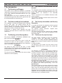
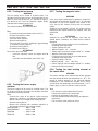
7.The Circuit Diagrams
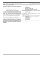
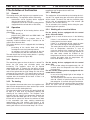
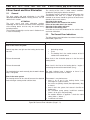
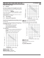
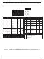
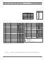
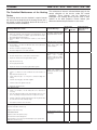
Cable colors
Cable Cross-section
< 7,5 m
7,5 - 15 m
0,75 mm2
1,5 mm2
1,0 mm2
1,5 mm2
1,5 mm2
2,5 mm2
2,5 mm2
4,0 mm2
4,0 mm2
6,0 mm2
Bl
Br
Ge
Gn
Gr
Or
Rt
Sw
Vi
ws
Blue
Brown
Yellow
Green
Grey
Orange
Red
Black
Violet
White
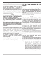
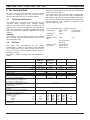
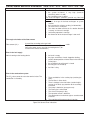
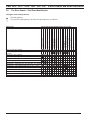
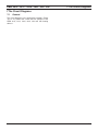
Pos.
Definition
Note
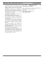
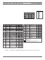
Pos.
Definition
A1
A2
B1
Heating device
Control device
Flame regulator
B2
Heat sensor
B3
Fan thermostat
M2
M3
P
S1
S2
S3
S4
S5
F1
Fuse A8 (for all types)
F2
F3
Fuse 8 A for all 24 V types +
DBW 2010 (12 V)
Fuse
F4
Fuse
F5
Thermal fuse
Without chassis
SG 1553
Pay attention to the pole
connection
Polarity connection makes
no difference
At water circuit for the
vehicle fan (ON – OFF)
Car fuse complying with
DIN 72581
Car fuse complying with
DIN 72581
Car fuse complying with
DIN 72581
Car fuse complying with
DIN 72581
Pole connection makes no
difference
G
H1
Battery
Illuminated diode, green
H2
Illuminated diode, yellow
X3
Y
1
H3
Lamps
H4
Illuminated diode, green
K1
K2
K3
K4
K5
Relay (at pos. A2)
Relay (at pos. A2)
Relay (at pos. A2)
Relay (at pos. A2)
Relay
Function indicator (at Pos.
P)
Indicator for ready status
(at Pos. P)
Symbol illumination (at
Pos. P)
Function indicator (when
S1 is used)
For the circulation pump
For the burner fan
For the induction bobbin
For the magnetic valve
It is only necessary at
negative when there is
battery switch
Motor
Burner fan
Motor
Vehicle fan
Program timer (digital)
For programmed work
Switch (ON-OFF)
For ON-OFF of the heating device
Switch
Battery switch
Switch
At the water faucet
Switch
Economy mode
Switch (for the vehicle
Alternative to Pos. S6
fan)
Switch (for the vehicle
Alternative to Pos. S5
fan)
Switch
Separate circulation pump, ON-OFF
Induction bobbin
With the ignition electrodes
Diode
Control device at Pos. A2
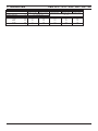
Cable bunch
Control device – heating device
Socket connection with
To Pos. P
8 pins
Socket connection with
2 pins
Socket connection
With 2 pins, at Pos. M2
Magnetic valve
Polarity makes no difference
Program timer P
Positive connection at 9 = continuous work at immediate
heating
Positive connection not at 9 = heating period 1 hour
Clamp 75, if available, in the vehicle direction, and clamp 75 if
not available
Vehicle illumination (clamp 58) Relay K5 and K6 with the
hatched lines only if the battery switch is used
Alternative
Vehicle clamp 15
K6
K7
Relay
Relay, for the vehicle fan
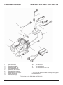
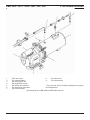
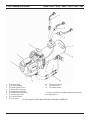
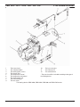
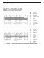
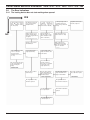
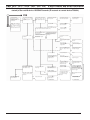
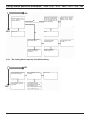
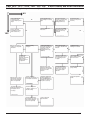
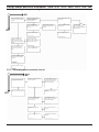
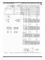
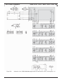
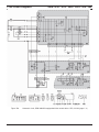
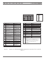
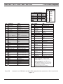
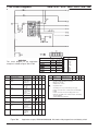
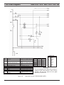
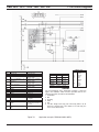
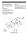
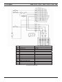
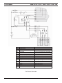
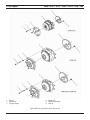
Figure 704
S6
S7
U
V1
W
X1
X2
2
3
4
5
6
Note
It is only necessary with B3
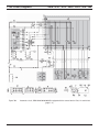
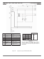
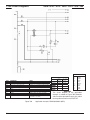
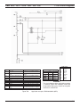
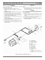
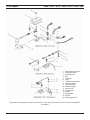
Automatic circuit, DBW 2010/2020/300/350 equipped with the control device 1563, 12 and 24 Volt
(page 2 / 2)
709