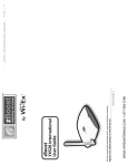
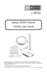
1
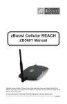
zBoost YX520 International User Guide 30 day money back guarantee when you buy directly from Wi-Ex®. If product is purchased from a reseller or third party, you must use their return policy. 1 Year Manufacturer Warranty. Register your zBoost® product at www.Wi-Ex.com v.11.10 zBOOST® YX520 INTERNATIONAL USER GUIDE zBOOST® YX520 INTERNATIONAL USER GUIDE About zBoost® from Wi-Ex® Wi-Ex® is the leader in cell phone signal boosters. zBoost® enhances the performance of your cell phone, PDA and wireless data card. Compatibility – Dual Band zBoosts are compatible with 900MHz and 1800MHz regardless of technology- including GSM, GPRS, EDGE, HSDPA Patented technologies protect the carrier network. 1-year manufacturer warranty – register your product at www.Wi-Ex.com. zBoost® products have more awards, more sales and more locations than all other signal boosters …COMBINED. Safety and Product Warranty Information Copyright Notice This manual is copyrighted. All rights reserved. This manual, whole or in part, may not be copied, photocopied, reproduced, translated or reduced to any electronic medium or machine readable form for distribution. This manual whole or in part, may not be modified without prior consent, in writing, from Wireless Extenders. Copyright © 2010 by Wireless Extenders, Inc. Trademarks Wireless Extenders, Wi-Ex, the Wi-Ex logo, zBoost, the zBoost logo and Extending Cell Zones are registered trademarks of Wireless Extenders, Inc. Safety Guidelines In accordance with FCC requirements of human exposure to radiofrequency fields, the radiating element (antenna) shall be positioned such that a minimum separation distance of 8 inches (20cm) is maintained between the radiating element and the user and/or general population. Limited Liability In no event shall Wireless Extenders be liable for any direct, indirect, special, punitive, incidental, exemplary or consequential damages, or any damages, whether in an action under contract, negligence, or any other theory, arising out of or in connection with the set up of, use of, inability to use, or performance of the information, services, products, and materials available from this manual. These limitations shall apply notwithstanding any failure of essential purpose of any limited remedy. Because some jurisdictions do not allow limitations on how long an implied warranty last, or the exclusion or limitation of liability for consequential or incidental damages, the above limitations may not apply to you. For full warranty guidelines, see page 15. Note Changes or modifications not expressly approved by Wi-Ex® could void the user’s authority to operate this equipment and/or void the product warranty. i 1. 2. zBOOST® YX520 INTERNATIONAL USER GUIDE zBOOST® YX520 INTERNATIONAL USER GUIDE International Certifications Read First Before Setting Up Your zBoost® The equipment you purcahsed has required the extraction and use of natural resources for its production. It may contain hazardous substances that could impact health and the environment. In order to avoid the dissemination of those substances in our environment and to diminish the pressure on the natural resources, we encourage you to use the appropriate take-back systems. Those systems will reuse or recycle most of the materials of your end life equipment in a sound way. 3. The crossed-out wheeled bin symbol invites you to use those systems. 4. If you need more information on the collection, reuse and recycling systems, please contact your local or regional waste administration. 5. You can also contact us for more information on the environmental performances of our products. Before unpacking the contents, verify that your mobile phone operates on the frequency band supported by this product. • zBoost® YX520i will enhance your in-building coverage for local provider networks operating at 900MHz and 1800MHz frequencies. Caution: Before beginning installation, you must have enough space to provide 5 meters of vertical separation between the Signal Aerial and Base Unit. Less than 5 meters will result in reduced performance. To verify that your mobile phone will work in conjunction with the model purchased, please follow these four simple steps: Unpack the Base Unit, Base Unit Aerial and power supply. 1. Connect the Base Unit Arial to the Base Unit. Choose the correct power adaptor for your geographical location and attach to the power supply. Connect the power supply to the Base Unit and plug into an outlet. The signal light should be solid green. 2. Now bring the unit (Base Unit, Power Supply and Base Unit Arial) to an area where there is enough signal to place a call (using an extension cord may be necessary). If the Signal light stays green while placing a call, you may proceed to the next step: Setting up your zBoost® Signal Booster. If it flashes red, move your mobile phone further away from the Base Unit and retry, it may be necessary to disconnect the power for 10 seconds and then reconnect the power. 3. If the Signal light does not stay a solid green, try placing another call with your mobile phone next to the Base Unit Aerial. If the Signal light still does stay green, your mobile phone may be operating on a frequency that is not supported by this zBoost model. Some carriers, change frequency depending on location. Email Wi-Ex technical support at [email protected], or call 001.800.871.1612 for further assistance in identifying your frequency. Base Unit Base Unit Aerial Adapters & Power Supply FIGURE 1: First, unpack the Base Unit, Base Unit Aerial, Power Supply and Adapters ii iii zBOOST® YX520 INTERNATIONAL USER GUIDE zBOOST® YX520 INTERNATIONAL USER GUIDE Package Contents: zBoost® YX520-I Optional zBoost® Accessories Before you begin, make sure all of the following parts came with your zBoost® YX-520i: To order, call 001-800-871-1612 or visit, www.Wi-Ex.com ② Set Up Overview (poster) ③ zBoost® YX-520i User Guide (manual) Product Contents: ⑤ zBoost® Base Unit with attached mounting bracket YX520i Set Up Tips (single sheet) YX500-PCS ① YX500-CEL The following accessories are available to improve signal reception and provide increased coverage in your home or office. Please see our website for more options. YX510-Dual Band Literature Contents: Part # X X X X YX012 X X X ⑥ X Base Unit Aerial X ⑦ ⑧ ⑨ ⑩ Rubber Feet Self-anchoring screws Description Outdoor Grounding Kit YX022-CEL Outdoor Omni-Directional Signal Aerial upgrade (6 dBi) YX023-PCS Outdoor Directional Signal Aerial upgrade (13 dBi) X YX023-GS9 Outdoor Directional Signal Aerial upgrade (8 dBi GSM900) X YX023-DCS Outdoor Directional Signal Aerial upgrade (13 dBi DCS) YX024-PCS Indoor Directional Base Unit Aerial (7 dBi) X X X YX025-CEL Outdoor Directional Signal Aerial upgrade (7 dBi) X X YX026-CEL Outdoor Directional Signal Aerial upgrade (11 dBi) YX027-PCS-CEL Indoor Dual Band Directional Base Unit Aerial upgrade (6 dBi/CEL, 9 dBi/PCS) YX069-PCS-CEL Outdoor Dual-Directional Signal Aerial upgrade (7 dBi/ CEL, 13 dBi/PCS) X YX029-DCS-GS9 Outdoor Dual-Directional Signal Aerial upgrade (8 dBi/ GS9, 13 dBi/DCS) X X X X X X X 75 Ohm Coaxial mini-RG59 Cable – 16 meters Power Supply and Adaptor Kit ⑪ Signal Aerial ⑫ Signal Aerial mounting hardware iv X X X X YX050-PCS-CEL Indoor Dual Band Omni-Directional Ceiling option for Base Unit Aerial (2 dBi) X X X X YX030-15W 15 ft. Outdoor coax extension, low-loss RG-6 X X X X YX030-35W 35 ft. Outdoor coax extension cable, low-loss RG-6 X X X YX031-10W 10 ft. Indoor coax extension cable for Base Unit Aerial X X X YX030-08W 8” white window entry flat cable X v zBOOST® YX520 INTERNATIONAL USER GUIDE Table of Contents About zBoost® from Wi-Ex® .........................................................................................................................i FCC Information .................................................................................................................................... i Industry Canada Regulations .................................................................................................................. i Safety and Product Warranty Information ..................................................................................................ii Copyright Notice ................................................................................................................................... ii Trademarks ............................................................................................................................................ ii Safety Guidelines ................................................................................................................................... ii Limited Liability .................................................................................................................................... ii International Certifications.........................................................................................................................ii Read First Before Setting Up Your zBoost® ................................................................................................ iii Package Contents: zBoost® YX520-I ..........................................................................................................iv Optional zBoost® Accessories ...................................................................................................................... v Table of Content .........................................................................................................................................1 Overview .....................................................................................................................................................2 Why Indoor Signals Can Be Weak ......................................................................................................... 2 Preparing to Set Up Your zBoost® Product ..................................................................................................3 Tools Needed ......................................................................................................................................... 3 Check for Signal Strength ...................................................................................................................... 3 Determine the Needed Coverage Area.................................................................................................... 4 Determine the Location of Signal Antenna and Base Unit Antenna ....................................................... 4 Additional Cable Requirements ............................................................................................................. 5 Securing Cable with a Drip Loop ........................................................................................................... 5 Power Requirements .............................................................................................................................. 5 Setting Up Your zBoost® Signal Booster ......................................................................................................6 Placement of the Signal Antenna............................................................................................................ 6 Easiest Set-Up ........................................................................................................................................ 6 Better Performance................................................................................................................................. 7 Best Performance ................................................................................................................................... 8 Positioning the Base Unit ..................................................................................................................... 10 Confirm That Your zBoost® is Working Properly .................................................................................. 10 Improving Your Coverage Area .................................................................................................................11 zBoost® Base Unit Light Indicators ...........................................................................................................12 YX520-I Technical Specifications ..............................................................................................................13 Frequently Asked Questions .....................................................................................................................14 zBoost® Warranty Information ...........................................................................................................15&16 1 zBOOST® YX520 INTERNATIONAL USER GUIDE zBOOST® YX520 INTERNATIONAL USER GUIDE Overview Thank you for choosing zBoost®. You will now be able to use your cell phone INSIDE your home or office. Gone are the days when you had to go to the window upstairs or walk outside to use your cell phone. Like a skylight that brings sunlight into your home, zBoost® transports and amplifies the outdoor cellular signals into your home or office. By following the easy instructions in this user guide, you will be Extending Cell Zones™ into your home or office. Why Indoor Signals Can Be Weak Preparing to Set Up Your zBoost® Product Tools Needed The following tools are needed to set up zBoost®: • #2 Philips screwdriver • Cellular phone operating in the band supported by your zBoost® unit • Drill (may be required for outdoor or attic antenna placement) There are several obstacles that can contribute to the poor reception you receive in your home or office: 1. Location of the Cell Phone Tower in Relation to Your Home/Office While cell phone providers have tried to place cell phone towers to provide the best overall coverage, local ordinances and terrain features can impose restrictions on where these towers can be placed, thus, limiting the signal strength available at your location. 2. Obstructions Caused by Buildings, Terrain and Trees Cell phone signals can be completely blocked or reflected by buildings, walls, trees, hills and other terrain features resulting in low signal strength. 3. Energy Efficient Windows These new windows can also affect signal penetration into the house Check for Signal Strength Before placing a zBoost® in your home, make sure that you can place calls on the outside of your home, in the attic, at roof level or wherever you plan to place the signal antenna. zBoost® can only bring signal into your home when signal reaches the Signal Antenna. If there is no signal, the zBoost® will not work for you. Using your cell phone, place a call from an outdoor location to confirm that enough signal is present to complete the call. If a weak signal is available at ground level, check the signal strength in your attic or at roof level location where the signal will likely be stronger and where the Signal Antenna can be placed for best performance. If you can reliably make and receive calls outside your home, then zBoost® can bring the signal into your home. If only one signal bar is displayed on your cell phone outside, indoor coverage will be limited to one small room. We recommend placing the Signal Antenna outside and/or purchasing a Wi-Ex® upgrade Signal Antenna for increased coverage (see page iv). Note Cell phone signal bars are approximate and vary from phone to phone. The number of bars can fluctuate widely, depending on the location of the phone, the position or angle of the phone, weather, etc. Most cell phone signal meters update every 6 to 10 seconds. An increase of only one bar typically indicates a 4x to 10x signal increase. 2 3 zBOOST® YX520 INTERNATIONAL USER GUIDE zBOOST® YX520 INTERNATIONAL USER GUIDE Determine Coverage Area Needed Additional Cable Requirements Identify the location in your home/office where you need signal coverage the most. The zBoost® YX520i can cover approximately 250 square meters (coverage varies based on outdoor signal level, building construction, and placement of aerials). Walls, ceilings or floors will reduce the coverage area. If the distance between the Signal Antenna and the Base Unit exceeds 50 feet, extension cables are available on our website or at many home improvement and electronic stores. The included cable is RG59-mini. For better performance, you may replace it with RG-6 cable for satellite TV. The total cable length should not exceed 70 feet unless you also purchase an upgraded signal antenna (see page iv). A longer cable is helpful only if it allows you to place the Signal Antenna in a location where you measure stronger signal. Grounding the Signal Antenna If you decide to place the Signal Antenna outdoors, it must be properly grounded. (See page iv for a recommented grounding kit). The set up must be in accordance with Article 810 of the National Electric Code (NEC). A listed antenna discharge unit must be provided for the lead-in coaxial cable per NEC article 8.10.20 or the shield of the coaxial cable must be permanently and effectively grounded in accordance with NEC article 8.10.21. Please consult a professional installer or electrician for more information. (See page iv). Securing Cable with a Drip Loop If you place the Signal Antenna outdoors, create a drip loop with the coaxial cable at the point where the cable enters the building through an outside wall. This can be done by twisting and securing the cable into a loop (no less than 4” across) near the entry point. This will help prevent moisture from gathering at entry point and leaking into the building. Consult a professional installer if you need more information. Exterior Wall Coax Cable Determine the Location of Signal Aerial and Base Unit Aerial Power Requirements It is recommended that the Signal Aerial and Base Unit Aerial have approximately 5 meters of vertical separation. The Base Unit can be plugged into a standard 2 or 3 prong 110 VAC receptacle using the Included power supply. The power supply consumes less than 10W (less than 0.2A). If the aerials are too close together, the signal light on the Base Unit will flash red indicating a problem (See Page 12, Troubleshooting). To capture the best signal, place the Signal Aerial as high as possible and position it vertically, keeping it at it at least 1 meter away from any metal. The location of the Signal Aerial should be at least 5 meters higher than the Base Unit Aerial. If this is not possible, maximizing the horizontal separation between the two aerials is advised. See page 6, Setting Up Your zBoost® Product, for additional information. Note Note Avoid placing the Signal Antenna near metal such as wiring, A/C ducts, metal siding, truss plates, etc. When connecting the cable to the antenna, run the cable straight down from the antenna. Avoid draping the coax near the antenna. 4 The zBoost® YX520-I base unit MUST only be used with the provided power adaptor. Use of other power adaptors will void the warranty and may damage the unit. Use of other equipment is not FCC approved. 5 zBOOST® YX520 INTERNATIONAL USER GUIDE Setting Up Your zBoost® Signal Booster zBOOST® YX520 INTERNATIONAL USER GUIDE BETTER PERFORMANCE: Outside of a window Locate a window where you get signal. Placement of the Signal Aerial 1. Locate a window where you get signal. Choose a location for the Signal Aerial that provides the best performance and the largest area of improved signal. Determine the location that provides the strongest signal using the signal strength indicator on your mobile phone. Find the location that provides the most bars of signal strength and place the Signal Aerial at or near that location. Avoid placing the Signal Aerial near metal such as wiring, A/C ducts, metal siding, truss plates, etc. When connecting the cable to the aerial, run the cable straight down from the aerial. Avoid draping the coax near the aerial. 2. Mount the Signal Aerial outside of the window. 3. Place the Base Unit in desired location – where you want to create a Cell Zone™ (5 meters of vertical separation between the Base Unit and Signal Aerial is recommended). Choose 1 of the following 3 options for setting up your zBoost® system: 4. Attach the coaxial cable to the Signal Aerial. 5. Run the coaxial cable from the Signal Aerial through the window (an optional window entry kit is available: see page v) and to the Base Unit. 6. Attach the Base Unit Aerial to the Base Unit and position it vertically. 7. Choose the appropriate power supply option for your location, connect the Power Supply to the Base Unit and plug into a power outlet. EASIEST: Inside, by a window Locate a window where you get service. 1. Mount the Signal Antenna above the window. The coverage your zBoost® provides is largely determined by the quality of signal received by the Signal Antenna. 2. Assemble the Base Unit Antenna. Place the Base Unit in desired location – where you want to create a Cell Zone™ (15 feet of vertical separation between the Base Unit and Signal Antenna is recommended). Connect the Base Unit Antenna to the Base Unit and place where you need signal. Easiest Performance Place the Signal Aerial it inside, by a window 3. Attach the coaxial cable to the Signal Antenna. 4. Connect the other end of the coaxial cable to the Base Unit. 5. Attach the Base Unit Antenna to the Base Unit and position it vertically. 6. Connect the Power Supply to the Base Unit and plug into a power outlet. Place Signal Antenna outside of window* NOTE: If the red light starts flashing, try further separating the Signal Aerial and Base Unit, disconnect power for 10 seconds and reconnect power or see the Troubleshooting section (Page 12) for further information. Upon initial power up, a solid GREEN light should appear indicating normal conditions. If a RED light appears, adjustments may be needed to optimize performance. If you find the increased signal coverage is acceptable, however, no additional adjustments are needed. See Light Indicator section (Page 12) for more information. NOTE: If a red light appears, try further separating the Signal Aerial and Base Unit or see the Troubleshooting section (Page 12) for further information. Upon initial power up, a solid GREEN light should appear indicating normal conditions. If a RED light appears, adjustments may be needed to optimize performance. If you find the increased signal coverage is acceptable, however, no additional adjustments are needed. See Light Indicator section (Page 12) for more 6 Better Performance 7 zBOOST® YX520 INTERNATIONAL USER GUIDE zBOOST® YX520 INTERNATIONAL USER GUIDE BEST PERFORMANCE: Attic/Outdoor placement The following instructions are recommended for the best reception: 1. Using your mobile phone as a signal meter, confirm that either your attic or your roof will deliver optimal signal strength to the Signal Aerial. Identify the best location for attachment of the mounting bracket – such as an attic cross or main beam. 2. Secure the mounting bracket at the highest possible point and at least 1 meter away from metal objects such as pipes, metal siding, A/C unit etc. 3. Position the mounting bracket such that the Signal Aerial will be vertical and attach the Signal Aerial (see figure 7). 4. Connect the supplied coaxial cable to the base of the Signal Aerial. 5. Run the coaxial cable along a descending pipe or through a wall that that leads closest to the location of the Base Unit. Best Performance Place the Signal Aerial in attic or on roof NOTE: Refrain from securing cable or drilling holes until the system has been tested. 6. From the other end, connect the coax cable it to the Base Unit. 7. Connect the Base Unit Aerial to the Base Unit and position it vertically. 8. Choose the appropriate power supply option for your location, connect the Power Supply to the Base Unit and plug into a power outlet. NOTE: If a red light appears, try further separating the Signal Aerial and Base Unit or see the Troubleshooting section (Page 12) for further information. More on Routing the Coaxial Cable Along side an Attic Pipe Locate a pipe that descends from the attic down to the desired location of the Base Unit. Tie a weight to a pull string and lower the weight down alongside the pipe. In the lower room, tie the pull-string 8 9 zBOOST® YX520 INTERNATIONAL USER GUIDE zBOOST® YX520 INTERNATIONAL USER GUIDE Spread Mounting Bracket tabs Positioning the Base Unit For the widest possible signal area, it is recommended that you position the zBoost® YX520i Base Unit near the middle of a room or mount it on an interior wall. This Base Unit uses an omni-directional aerial that delivers signal in a circular pattern around the aerial. If you decide to position the Base Unit on or near an outside wall, we recommend purchasing a Directional Base Unit Aerial (Page v) to focus the signal in the direction of your choice. The Base Unit can be mounted either directly on a wall or placed on a flat surface (e.g., a bookshelf, desk, end table, etc.). The Base Unit performs best when located at least 1-2 meters above the floor or approximately the height of a mobile phone when it is typically in use (avoid placing the Base Unit on the floor). For best results, avoid placing the Base Unit Aerial within 1 meter of other cords, metal objects or other wireless devices such as wireless routers or wireless access points. Confirm That Your zBoost® is Working Properly Perform the following steps to confirm that the unit is now working properly: Improving Your Coverage Area When your zBoost® system is in place and fully connected, you should walk throughout the room and see that you are able to reliably place calls. 1. Unplug the Base Unit power cable. Remember, coverage varies based on outdoor signal level, building construction, and aerial placement. Coverage in adjoining rooms (next to, above, or below) will be reduced due to walls or ceiling/floors. 2. Turn on your mobile phone and check the number of bars. Should you desire to improve coverage, you may: 3. Plug the power cable into the Base Unit. • Move the Base Unit and/or adjust the angle of the Base Unit Aerial. 4. Hold your mobile phone about 2 meters from the Base Unit and then turn it on. Wait up to 1 minute for the mobile phone to register the signal coming from the Base Unit. • Move the Signal Aerial to a higher location in your attic or outside. • Purchase a Signal Aerial Upgrade (see page v). If the number of bars shows improvement, your zBoost® unit is working properly. • Purchase a Base Unit Aerial Upgrade (see page v). 5. The Base Unit can also be easily mounted to a wall using the included mounting bracket hardware. The Base Wall Mounting the Base Unit Perform the following steps to mount the Base Unit to a wall: 1. Remove the mounting bracket from the Base Unit by firmly spreading one of the tabs outward from the base unit as illustrated in figure 8. 2. Fasten the mounting bracket to the wall using the included wall/ceiling anchors. 3. Snap the Base Unit into the mounting bracket. Note Cell phone signal bars are approximate and vary from phone to phone. The number of bars can fluctuate widely, depending on the location of the phone, the position or angle of the phone, weather, etc. Most cell phone signal meters update every 6 to 10 seconds. An increase of only one bar typically indicates a 4x to 10x signal increase. THE BEST INDICATOR OF PRODUCT PERFORMANCE IS THE ABILITY TO RELIABLY PLACE AND RECEIVE CALLS WHERE YOU COULD NOT BEFORE SETTING UP THE YX520-I. 10 11 zBOOST® YX520 INTERNATIONAL USER GUIDE zBOOST® YX520 INTERNATIONAL USER GUIDE zBoost® Base Unit Light Indicators Technical Specifications At Initial Power Up Only Solid GREEN Normal condition at power up. Slowly Alternating RED and GREEN zBoost® is working, but at reduced performance and coverage due to “nonideal” setup. Solution: Increase the distance between antenna and amplifier to achieve maximum performance and coverage. Indicates insufficient distance between the antenna and the amplifier. The amplifier is operating at significantly reduced coverage. Fast Flashing RED Solution: Increase space between base unit and antenna. System is receiving signals from either the mobile device or the base station transceiver which are too strong for proper operation. Solid RED Solutions: Move away from receiving antenna with your cell phone. Move antenna away from other devices.. The amplifier is disabled. Fast Alternating RED and GREEN followed by no light YX520-I Technical Specifications Frequency: 890-960 MHz 1710 -1880 MHz Networks: GSM, GPRS, EDGE, HSDPA Total Signal Gain: 50 dB (Adaptive) GSM900 50 dB (Adaptive) DCS Signal Aerial Gain: 0dBi Dipole; F-Type Connector Base Unit Aerial Gain: 0dBi whip; SMA male Cable Loss: 5 dB (16 meters of 75Ω, 3000 MHz mini RG-59) GSM900 9 dB (16 meters of 75Ω, 3000 MHz mini RG-59) DCS RF Output Power: 100 mW GSM900 100 mW DCS Base Unit Weight: 15 oz. Base Unit Size: 5” x 7” x 1” AC Power Input: 100 – 240 VAC, 47 – 63Hz DC Power Output: 3.7 VDC, 2.0 A Operating Conditions: Indoor use only 5° to 40°C (40° to 105°F) Coverage (open areas): 4-5 signal bars at roof aerial; 60’ diameter at 3-4 bars inside; 250 square meters circle Solution: Unplug and start over. After Initial Power Up Solid GREEN Normal condition. Solid RED System is receiving signals from either the mobile device or the base station transceiver which are too strong for proper operation. Solution: Please unplug your system. Re-orient your Signal Antenna and/or Base Unit to reduce the excessive signal source. Plug your system back in. If still solid red, call customer support 001-800-871-1612. 12 13 zBOOST® YX520 INTERNATIONAL USER GUIDE zBOOST® YX520 INTERNATIONAL USER GUIDE Frequently Asked Questions Warranty Information Limited 1 Year Warranty What can I expect my cell phone signal range and strength to be inside my home or office? The closer you are to the base, the stronger the signal. This will vary with different conditions. Some of the conditions that will affect the improved coverage area are signal strength outdoors, the type of building materials in the home, the placement of the unit and the antenna’s proximity to cellular towers. You can expect that your indoor coverage will be improved. You will be able to make calls where you couldn’t before. The degree of improvement will depend upon many factors. The intent of zBoost® products are to bring outside coverage inside. Just as the signal bars move up and down when outside, the boosted signal will fluctuate in a similar fashion. Is a cellular phone signal booster the same as a wireless router; will it help my WiFi signal? The Wi-Ex® unit will not help your WiFi service. This unit is designed to work with wireless PCS and Cellular phones and devices. The WIFI in your home or office operates on a different frequency. Register your product at www.Wi-Ex.com Wi-Ex® warrants every Wi-Ex® product to be free from defects in material and workmanship under normal use for the warranty period of one year. Who Is Covered? You must have proof of purchase to receive warranty service. A sales receipt or other documentation showing the product purchased and the purchase date is considered proof of purchase. This limited warranty extends only to the original consumer purchaser or any person receiving the product as a gift from the original consumer purchaser and to no other purchaser or transferee. This warranty does NOT extend to commercial users. What is Covered? Is your product available for international use? The YX520i is the international model. We also sell zBoost® ONE YX400-U for UMTS/HSPA devices on the 2100MHz Frequency, a frequency used for voice and data overseas. Check the frequencies for a particular country for compatibility. Check our website www.Wi-Ex.com for product availability. Warranty coverage begins the day you purchase the product. For one year from the original date, the Wi-Ex® Cell Phone Signal Booster will be repaired or replaced with a new, repaired, refurbished or comparable product (whichever is deemed necessary by Wi-Ex® ) if it becomes defective or inoperative. The exchange will be made without charge to you for parts and labor. You will be responsible for the cost of shipping to the location designated by Wi-Ex®. All products, including replacement products, are covered only for the original warranty period. When the warranty on the original product expires, the warranty on the replacement product also expires. Why isn’t my cell phone indicating more signal with more bars? You may not always observe more bars that gain on your signal meter because of the signal spreading out from the antenna. If your phone has a dB meter, 3dB is a significant increase of 2x, 6dB is 4x, and 10dB is 10x. On a four bar phone, one "bar" equals about 10dB. The increase in signal you will see depends upon: What is Excluded? Your warranty does NOT cover: • Labor charges for set up of the unit. • Product replacement because of misuse, accident, lightning damage, unauthorized repair or other cause not within the control of Wi-Ex®. • The level of signal at the Signal antenna (outdoor) • The care of the antenna placement (two feet away from metal, adequate antenna separation [15 feet recommended]) • Incidental or consequential damages resulting from the product. Some states do not allow the exclusion of incidental or consequential damages, so the above exclusion may not apply to you. • The signal already present inside (related to building losses) • • The distance of your phone/device from the Base Unit (signal spreads or diminishes rapidly with distance.) Any modifications or other changes to the product, including but not limited to software or hardware modifications in any way other than as expressly authorized by Wi-Ex® will void this limited warranty. • Product that has been modified or adapted to enable it to operate in any country other than the country for which it was designed, manufactured, approved and/or authorized, or repair of products damaged by these modifications. There are usually several cell phones in use at one time in my home, will your product boost all of our signals simultaneously? The zBoost® YX520-I is designed to cover multiple signals simultaneously and will allow multiple users to operate at the same time. Does the zBoost® work if you have no bars? No, if no signal is present outdoors zBoost® producs will not work for you. Also, keep in mind if your best signal is 1 bar at the Signal Antenna, your coverage will be limited to a small room. You could improve that with an upgraded antenna. (See page iv). 14 15 zBOOST® YX520 INTERNATIONAL USER GUIDE Make sure you keep… Please keep your sales receipt or other document showing proof of purchase. Attach it to this User Guide and keep both nearby. Also, keep the original box and packing material in case you need to return your product. Before requesting repair service… If red light is on, system is receiving signals from either the mobile device or the base station transceiver which are too strong for proper operation. Please unplug your system. Re-orient your Signal Antenna and/or Base Unit to reduce the excessive signal source. Plug your system back in. If still solid red, call customer support 1-800-8711612. To get warranty service… Warranty service will be provided by Wi-Ex®. If you believe you need service for your unit, contact Wi-Ex® at 1-800-871-1612 or [email protected]. A representative will go through a diagnostic checklist with you. If it is determined that the product needs to be returned for service or exchanged, you will receive a return merchandise authorization (RMA) number. The representative will give you complete shipping details. Do not return products to Wi-Ex® without a Return Authorization Number (RMA). To get out of warranty service… To obtain out of warranty service, contact Wi-Ex® at 1-800-871-1612 or [email protected] for information on the possibility of any costs for repair or replacement of out-of-warranty products. Reminder Record the model and serial number found on the product below: Model #: __________________________________ Serial #: ___________________________________ Purchase Date: ____________________________ 16