1
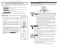
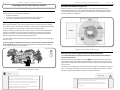
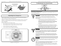
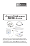
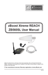
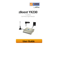
i
|
Page
ZBOOST® YX500/510 SERIES USER GUIDE
About zBoost® from Wi-Ex®
Wi-Ex is the leader in cell phone signal boosters. zBoost® enhances the performance of your cell phone,
smartphone, PDA and wireless data card.
Compatibility – Dual Band zBoosts are compatible with all US carriers regardless of technology (Except
iDEN, Nextel).
Patent-pending technologies protect the carrier network.
1-year manufacturer warranty – register your product at www.Wi-Ex.com
zBoost® products have more awards, more sales and more locations –
more than all other signal boosters … COMBINED.
FCC Information
FCC ID: SO4YX500-CEL
: SO4YX510-PCS
: SO4YX500-PCS
: SO4YX510
: SO4YX510-CEL
Warning: Changes or modifications to this device not expressly approved by Wi-Ex could void the user’s
authority to operate the equipment.
Note: This equipment has been tested and found to comply with the limits for a Class B digital device,
pursuant to Part 15 of the FCC Rules. These limits are designed to provide reasonable protection against
harmful interference in a residential installation. This equipment generates, uses, and can radiate radio
frequency energy and, if not installed and used in accordance with the instructions, may cause harmful
interference to radio communications. However, there is no guarantee that interference will not occur in a
particular installation. If the equipment does cause harmful interference to radio or television reception,
which can be determined by turning the equipment off and on, the user is encouraged to try to correct the
interference by one or more of the following measures:
•
•
•
•
Reorient or relocate the receiving antenna.
Increase the separation between the equipment and receiver.
Connect the equipment to an outlet on a circuit different from that to which the receiver is connected.
Consult the dealer or an experienced radio/TV technician for help.
RF Exposure:
This equipment complies with FCC radiation exposure limits set forth for an uncontrolled environment. This
transmitter must not be co-located or operating in conjunction with any other antenna or transmitter.
Industry Canada Regulations
Canada IC :5544A-YX500CEL
:5544A-YX510PCS
:5544A-YX500PCS
:5544A-YX510
:5544A-YX510CEL
This Class B digital apparatus meets all requirements of the Canadian Interference Causing Equipment
Regulations. Operation is subject to the following two conditions: (1) this device may not cause harmful
interference, and (2) this device must accept any interference received, including interference that may
cause undesired operation.
The term “IC:” before the radio certification number only signifies that Industry Canada technical
specifications were met.
RF Exposure:
The manufacturer’s rated output power of this equipment is for single carrier operation. For situations
when multiple carrier signals are present, the rating would have to be reduced by 3.5 dB, especially where
the output is re-radiated and can cause interference to adjacent band users. This power reduction is to be
by means of input power or gain reduction and not by an attenuator at the output of the device.
ZBOOST® YX500/510 SERIES USER GUIDE
Page
|
ii
Cet appareillage numérique de la classe [B] répond à toutes les exigences de l'interférence canadienne
causant des règlements d'équipement. L'opération est sujette aux deux conditions suivantes: (1) ce
dispositif peut ne pas causer l'interférence nocive, et (2) ce dispositif doit accepter n'importe quelle
interférence reçue, y compris l'interférence qui peut causer l'opération peu désirée.
Le fabricant nominale de la puissance de sortie de ce matériel est simple transporteur. Pour les situations
lorsque plusieurs signaux porteurs sont présents, l'évaluation devrait être réduite de 3,5 dB, en particulier
lorsque le signal de sortie est ré-émise et peut provoquer des interférences adjacentes à la bande
utilisateurs. Ce pouvoir est de la réduction par le biais de la sortie d'alimentation ou la réduction de gain
et non par un atténuateur à la sortie du dispositif.
Copyright Notice
This manual is copyrighted. All rights reserved. This manual, whole or in part, may not be copied,
photocopied, reproduced, translated or reduced to any electronic medium or machine readable form for
distribution. This manual whole or in part, may not be modified without prior consent, in writing, from
Wireless Extenders.
Copyright © 2008 by Wireless Extenders, Inc.
Trademarks
Wireless Extenders, Wi-Ex, the Wi-Ex logo, zBoost, the zBoost logo and Extending Cell Zones are registered
trademarks of Wireless Extenders, Inc.
Safety and Product Warranty Information
Safety Guidelines
In accordance with FCC requirements of human exposure to radiofrequency fields, the radiating element
(antenna) shall be positioned such that a minimum separation distance of 8 inches (20cm) is maintained
between the radiating element and the user and/or general population.
Limited Liability
In no event shall Wireless Extenders be liable for any direct, indirect, special, punitive, incidental,
exemplary or consequential damages, or any damages, whether in an action under contract, negligence,
or any other theory, arising out of or in connection with the set up of, use of, inability to use, or
performance of the information, services, products, and materials available from this manual. These
limitations shall apply notwithstanding any failure of essential purpose of any limited remedy. Because
some jurisdictions do not allow limitations on how long an implied warranty last, or the exclusion or
limitation of liability for consequential or incidental damages, the above limitations may not apply to you.
For full warranty guidelines, see page 19.
Warning
Changes or modifications not expressly approved by
Wi-Ex could void the user’s authority to operate this
equipment and/or void the product warranty.
iii
|
Page
ZBOOST® YX500/510 SERIES USER GUIDE
ZBOOST® YX500/510 SERIES USER GUIDE
Read First Before Setting Up Your zBoost®
o
zBoost® YX500-CEL will enhance your in-building coverage for local provider networks
operating at the 800MHz (Cellular) frequency.
o
zBoost® YX500-PCS will enhance your in-building coverage for local provider networks
operating at the 1900MHz (PCS) frequency.
NOTE: The zBoost® YX500/510 Series is not compatible with iDEN, Nextel, SMR or ESMR
frequency services.
To verify that your phone will work in conjunction with the model purchased, please follow
these four simple steps:
Unpack the Base Unit, Base Unit Antenna and power supply.
2)
Connect the Base Unit Antenna and the power supply to Base
Unit and plug it into an outlet. The green power light ( )
should illuminate.
3)
Bring the unit to an area where there is enough signal to place
a call (using an extension cord may be necessary). If the Signal
light ( ) begins flashing while placing a call, you may proceed
to the next step: Setting up your zBoost® Signal Booster. If it
flashes red, move your phone further away from the Base Unit
and retry.
4)
If the Signal light ( ) does not flash green, try placing another
call with your cell phone next to the Base Unit antenna. If the
Signal light ( ) still does not flash green, your cell phone may
be operating on a frequency supported by a different model.
Some carriers, such as AT&T and Verizon change frequency
depending on location. Go to www.wirelessadvisor.com, email
Wi-Ex technical support at [email protected], or call
1-800-871-1612 for further assistance in identifying your
frequency.
iv
Upon initial power-up of your zBoost®, all lights may flash for approximately 5 seconds. This is a
normal condition at power-up. For more detailed information on Base Unit light indicators, see
page the Troubleshooting section on page 12.
INSTALL
zBoost® YX510-Dual Band will work for both Cellular and PCS frequencies.
1)
|
zBoost® Base Unit Light Indicators
Before unpacking the contents, verify that your phone operates on the frequency band
supported by this product.
o
Page
FIGURE 1: First,
unpack the Base
Unit, Base Unit
Antenna and
Power Supply
Base Unit
POWER
SIGNAL
Install Light
The condition of the Install light reflects the quality of the installation. Following
initial power-up, a red (solid or blinking) Install light indicates that the positioning
of zBoost® component(s) is reducing the performance of your zBoost® system.
1.
It may be that you are receiving an acceptable signal boost; however,
repositioning the Signal Antenna and/or Base Unit Antenna to maximize
separation between the Signal Antenna and the Base Unit will improve
your zBoost® performance. See page 4, Determine the Location of Signal
Antenna and Base Unit Antenna for more information.
2.
A red Install light accompanied with a red Signal light may indicate that the
signal received from a cell tower is too strong. To reduce the overpowering
signal, relocate the Signal Antenna to an area that receives less signal,
which may be indoors or a lower elevation.
Signal Light
INSTALL
POWER
SIGNAL
Base Unit
Antenna
Power Supply
The Signal light indicates the condition of communication between a wireless
device and its cellular network. Following initial power-up, the Signal light will
flash green (800MHz band) when a call is in progress or periodically during normal
network communication.
A red Install light accompanied with a red Signal light may indicate that the signal
received from a cell tower is too strong. To reduce the overpowering signal,
relocate the Signal Antenna to an area that receives less signal, which may be
indoors or a lower elevation.
Power Light
The Power light indicates operation under normal or abnormal conditions.
Following initial power-up, the presence of a solid green Power light indicates
normal conditions.
While in use, an alternating orange or solid green Power light (with no other
negative indicators by the Signal or Install light) reflects normal conditions.
A flashing green Power light (without any other indicators from the Install or
Signal light) means that a software error has been detected. Reset by removing
power and reconnecting after 10 seconds.
Other conditions are noted on page 12 in the Troubleshooting section.
v
|
ZBOOST® YX500/510 SERIES USER GUIDE
Page
ZBOOST® YX500/510 SERIES USER GUIDE
Package Contents: zBoost® YX500-CEL
Package Contents: zBoost® YX510-PCS-CEL
Before you begin, make sure all of the following parts came with your zBoost® YX510-Dual-Band:
Literature Contents:
①
Set Up Tips (single sheet)
②
Set Up Overview (poster)
③
zBoost® YX500/510 User Guide (manual)
④
zBoost® Optional Accessories (single sheet)
Before you begin, make sure all of the following parts came with your zBoost® YX500-CEL:
Literature Contents:
①
Before Unpacking this Box (single sheet)
②
Set Up Overview (poster)
③
zBoost® YX500/510 User Guide (manual)
Product Contents:
④
zBoost® Optional Accessories (single sheet)
⑤
Product Contents:
zBoost® Base Unit with attached
mounting bracket
⑥
Base Unit Antenna – 0 dBi
⑦
Rubber Feet
⑧
Self-anchoring screws
⑨
Coaxial Cable – 50 ft
⑩
Power Supply
⑪
⑫
Page
⑤
⑤
zBoost® Base Unit with attached
mounting bracket
⑥
Base Unit Antenna – 0 dBi
⑦
Rubber Feet
⑧
Self-anchoring screws
⑨
Coaxial Cable – 50 ft
Signal Antenna
⑩
Power Supply
Signal Antenna mounting hardware
⑪
Signal Antenna
⑫
Signal Antenna mounting hardware
⑥
⑧
⑦
⑨
⑤
⑥
⑧
⑦
⑨
⑩
⑪
⑩
⑪
⑫
⑫
|
vi
vii
|
ZBOOST® YX500/510 SERIES USER GUIDE
Page
ZBOOST® YX500/510 SERIES USER GUIDE
Package Contents: zBoost® YX500-PCS
Page
|
viii
Optional zBoost® Accessories
The following accessories are available to improve signal reception and provide increased
coverage in your home or office. Please see our website for more options.
Before you begin, make sure all of the following parts came with your zBoost® YX500-PCS:
Literature Contents:
Set Up Overview (poster)
③
zBoost® YX500/510 User Guide (manual)
④
zBoost® Optional Accessories (single sheet)
YX500-PCS
②
To order, call 1-800-871-1612 or visit, www.Wi-Ex.com for a complete listing
YX500-CEL
Before Unpacking this Box (single sheet)
YX510-Dual Band
①
Part #
zBoost® Base Unit with attached
mounting bracket
X
X
X
YX012
X
X
⑥
Base Unit Antenna – 0 dBi
X
X
YX023-PCS
Outdoor Directional Signal Antenna upgrade (13 dBi)
⑦
X
X
YX024-PCS
Indoor Directional Base Unit Antenna (7 dBi)
Rubber Feet
⑧
Self-anchoring screws
⑨
Coaxial Cable – 35 ft
⑩
Power Supply
⑪
Signal Antenna
⑫
Signal Antenna mounting hardware
Product Contents:
⑤
⑤
⑥
⑦
⑧
⑨
⑩
⑪
⑫
Description
Outdoor Grounding Kit
YX022-CEL
Outdoor Omni-Directional Signal Antenna upgrade (6 dBi)
X
X
YX025-CEL
Outdoor Directional Signal Antenna upgrade (7 dBi)
X
X
YX026-CEL
Outdoor Directional Signal Antenna upgrade (11 dBi)
X
X
X
YX027-PCS-CEL
Indoor Dual Band Directional Base Unit Antenna upgrade
(6 dBi/CEL, 9 dBi/PCS)
X
X
X
YX029-PCS-CEL
Outdoor Bi-Directional Amplifier System Signal Antenna
upgrade (7 dBi/CEL, 13 dBi/PCS)
X
X
X
YX050-PCS-CEL
X
X
X
X
X
X
X
YX030-15W
X YX030-35W
Indoor Dual Band Omni-Directional Ceiling option for Base
Unit Antenna (2 dBi)
15 ft. Outdoor coax extension cable, low-loss RG-6
35 ft. Outdoor coax extension cable, low-loss RG-6
X
X
YX031-10W
10 ft. Indoor coax extension cable for Base Unit Antenna
X
X
YX030-08W
8” white window entry flat cable
1
|
Page
ZBOOST® YX500/510 SERIES USER GUIDE
Table of Content
About zBoost® from Wi-Ex®..................................................................................................................................... i
FCC Information ............................................................................................................................................................... i
Industry Canada Regulations...................................................................................................................................... i
Copyright Notice.............................................................................................................................................................. ii
Trademarks ....................................................................................................................................................................... ii
Safety and Product Warranty Information ........................................................................................... ii
Safety Guidelines ............................................................................................................................................................. ii
Limited Liability .............................................................................................................................................................. ii
Read First Before Setting Up Your zBoost® .........................................................................................iii
zBoost® Base Unit Light Indicators....................................................................................................................... iv
Package Contents: zBoost® YX510-PCS-CEL ........................................................................................ v
Package Contents: zBoost® YX500-CEL ................................................................................................ vi
Package Contents: zBoost® YX500-PCS ............................................................................................... vii
Optional zBoost® Accessories............................................................................................................... viii
Table of Content ............................................................................................................................................. 1
Overview ............................................................................................................................................................................. 2
Why Indoor Signals Can Be Weak ............................................................................................................................ 2
Preparing to Set Up Your zBoost® Product .......................................................................................... 3
Tools Needed .................................................................................................................................................................... 3
Check for Signal Strength ............................................................................................................................................ 3
Determine the Needed Coverage Area................................................................................................................... 4
Determine the Location of Signal Antenna and Base Unit Antenna .......................................................... 4
Additional Cable Requirements ................................................................................................................................ 5
Grounding the Signal Antenna .................................................................................................................................. 5
Securing Cable with a Drip Loop .............................................................................................................................. 5
Power Requirements ..................................................................................................................................................... 5
Setting Up Your zBoost® Signal Booster................................................................................................ 6
Placement of the Signal Antenna .............................................................................................................................. 6
Easiest Set-Up .................................................................................................................................................. 6
Better Performance ...................................................................................................................................... 7
Best Performance .......................................................................................................................................... 8
Positioning the Base Unit ......................................................................................................................................... 10
Confirm That Your zBoost® is Working Properly ........................................................................................ 10
Wall Mounting the Base Unit .................................................................................................................................. 10
Improving Your Coverage Area ...............................................................................................................11
Troubleshooting Your zBoost® System ...............................................................................................12
zBoost® Base Unit Light Indicators .................................................................................................................... 12
Base Unit Indicator Operation................................................................................................................................ 13
YX510-PCS-CEL Technical Specifications ............................................................................................................... 14
YX500-CEL Technical Specifications......................................................................................................................... 14
YX500-PCS Technical Specifications ......................................................................................................................... 15
Frequently Asked Questions ....................................................................................................................16
zBoost® Warranty Information ..............................................................................................................19
ZBOOST® YX500/510 SERIES USER GUIDE
P A G E
|
2
Overview
Thank you for choosing zBoost®. You will now be able to use your cell phone INSIDE your home
or office. Gone are the days when you had to go to the window upstairs or walk outside to use
your cell phone. Like a skylight that brings sunlight into your home, zBoost® transports and
amplifies the outdoor cellular signals into your home or office.
By following the easy instructions in this user guide, you will be Extending Cell Zones™ into your
home or office.
Why Indoor Signals Can Be Weak
There are several obstacles that can contribute to the poor reception you receive in your home
or office:
1) Location of the Cell Phone Tower in Relation to Your Home/Office
While cell phone providers have tried to place cell phone towers to provide
the best overall coverage, local ordinances and terrain features can impose
restrictions on where these towers can be placed, limiting the signal strength
available at your location.
2) Obstructions Caused by Buildings, Terrain and Trees
Cell phone signals can be completely blocked or reflected by buildings, walls, trees,
hills and other terrain features resulting in low signal strength.
FIGURE 2: Cell Phone Signal Obstructions
3
|
ZBOOST® YX500/510 SERIES USER GUIDE
Page
Preparing to Set Up Your zBoost® Product
Tools Needed
The following tools are needed to set up zBoost®:
•
#2 Philips screwdriver
•
Cellular phone operating in the band supported by your zBoost® unit
•
Drill (may be required for outdoor or attic antenna placement)
ZBOOST® YX500/510 SERIES USER GUIDE
Page
|
4
Determine the Needed Coverage Area
Identify the location in your home/office where you need signal coverage the most. The
zBoost® YX500/510 Series can cover approximately 2500 square feet (coverage varies based
on outdoor signal level, building construction, and placement of antennas). Walls, ceilings or
floors will reduce the coverage area.
Check for Signal Strength
Before placing a zBoost® in your home, make sure that you can place calls on the outside of
your home, in the attic, at roof level or wherever you plan to place the signal antenna. zBoost®
can only bring signal into your home when signal reaches the Signal Antenna.
Using your cell phone, place a call from an outdoor location to confirm that enough signal is
present to complete the call. If a weak signal is available at ground level, check the signal
strength in your attic or at roof level location where the signal will likely be stronger and
where the Signal Antenna can be placed for best performance.
If you can reliably make and receive calls outside your home, then zBoost® can bring the signal
into your home.
If only one signal bar is displayed on your cell phone outside, indoor coverage will be limited
to one small room. We recommend placing the Signal Antenna outside and/or purchasing a
Wi-Ex® upgrade Signal Antenna (see page viii).
FIGURE 4: zBoost® Base Unit Coverage
Determine the Location of Signal Antenna and Base Unit Antenna
It is recommended that the Signal Antenna and Base Unit Antenna have approximately 15
feet of vertical separation.
If the antennas are too close together, the Install ( ) light on the Base Unit will be lit or flash
red indicating a problem (See Page 12, Troubleshooting). To capture the best signal, place the
Signal Antenna as high as possible and position it vertically, keeping it at it at least 2 feet away
from any metal.
FIGURE 3: Checking Signal Strength
The location of the Signal Antenna should be at least 15 feet higher than the Base Unit Antenna.
If this is not possible, maximizing the horizontal separation between the 2 antennas is advised.
See page 6, Setting Up Your zBoost® Product, for additional information.
Note
Cell phone signal bars are approximate and vary from phone
to phone. The number of bars can fluctuate widely,
depending on the location of the phone, the position or angle
of the phone, weather, etc. Most cell phone signal meters
update every 6 to 10 seconds. An increase of only one bar
typically indicates a 4x to 10x signal increase.
THE BEST INDICATOR OF SIGNAL STRENGTH IS THE ABILITY TO
RELIABLY PLACE AND RECEIVE CALLS.
Warning
Avoid placing the Signal Antenna near metal such as wiring,
A/C ducts, metal siding, truss plates, etc.
When connecting the cable to the antenna, run the cable
straight down from the antenna. Avoid draping the coax near
the antenna.
5
|
Page
ZBOOST® YX500/510 SERIES USER GUIDE
Page
ZBOOST® YX500/510 SERIES USER GUIDE
|
6
Setting Up Your zBoost® Signal Booster
Additional Cable Requirements
If the distance between the Signal Antenna and the Base Unit exceeds 35 feet (YX500-PCS) or
50 feet (YX500-CEL or YX510-Dual Band), you will need to purchase additional coaxial cable for
a total coax cable length of 70 feet. You may use RG-6 coaxial cable and F connectors, which
are rated for outdoor satellite TV use and can be found at many home improvement and
electronic stores.
Placement of the Signal Antenna
For the best performance, purchase RG-6 low-loss extension cables from our website or your
retailer. The total cable length should not exceed 70 feet unless you also purchase an
upgraded signal antenna (see page viii). A longer cable is helpful only if it allows you to place
the Signal Antenna in a location where you measure stronger signal.
Choosing the best location for the Signal Antenna provides the best performance and the
largest area of improved signal. Determine the location that provides the strongest signal using
the signal strength indicator on your cell phone. Find the location that provides the most bars
of signal strength and place the Signal Antenna at or near that location. Avoid placing the Signal
Antenna near metal such as wiring, A/C ducts, metal siding, truss plates, etc. When connecting
the cable to the antenna, run the cable straight down from the antenna. Avoid draping the coax
near the antenna.
Grounding the Signal Antenna
Choose 1 of the following 3 options for setting up your zBoost® system:
If you decide to place the Signal Antenna outdoors, it must be properly grounded.
The set up must be in accordance with Article 810 of the National Electric Code (NEC). A listed
antenna discharge unit must be provided for the lead-in coaxial cable per NEC article 8.10.20
or the shield of the coaxial cable must be permanently and effectively grounded in
accordance with NEC article 8.10.21. Please consult a professional installer or electrician for
more information. Additional instructions and hardware are also available in the zBoost®
Outdoor Grounding Kit (see page viii).
Securing Cable with a Drip Loop
If you place the Signal Antenna outdoors, create a drip loop with
the coaxial cable at the point where the cable enters the building
through an outside wall. This can be done by twisting and securing
the cable into a loop (no less than 4” across) near the entry point.
This will help prevent moisture from gathering at entry point and
leaking into the building. Consult a professional installer if you
need more information. Additional instructions are also available
in the zBoost® Outdoor Grounding Kit (see page viii).
Coax
Cable
➊
EASIEST:
Inside, by a window
1. Locate a window where you get signal.
2. Mount the Signal Antenna above the window.
3. Place the Base Unit in desired location – where you
want to create a Cell Zone™ (15 feet of vertical
separation between the Base Unit and Signal
Antenna is recommended).
4. Attach the coaxial cable to the Signal Antenna.
5. Connect the other end of the coaxial cable to the
Base Unit.
Easiest Set-Up:
Place the Signal Antenna
inside, by a window
6. Attach the Base Unit Antenna to the Base Unit and
position it vertically.
7. Connect the Power Supply to the Base Unit and plug into a power outlet.
NOTE: If a red light appears, try further separating the Signal Antenna and Base Unit or see the
Troubleshooting section (Page 12).
Exterior Wall
FIGURE 5: Securing
Cable with a Drip Loop
Signal
Antenna
Power Requirements
The Base Unit can be plugged into a standard 2 or 3 prong 110 VAC receptacle using the
Included power supply. The power supply consumes less than 10W (less than 0.2A).
Base
Uni t
Warning
The zBoost® YX500/510 Series base unit MUST only be used
with the provided power adaptor. Use of other power adaptors
will void the warranty and may damage the unit. Use of other
equipment is not FCC approved.
Power
Supply
Coax
Cable
FIGURE 6: Placing the Signal Antenna Inside, Near a Window
7
|
ZBOOST® YX500/510 SERIES USER GUIDE
Page
➋
➌
BETTER PERFORMANCE:
Outside of a window
Page
ZBOOST® YX500/510 SERIES USER GUIDE
|
8
BEST PERFORMANCE: Attic/Outdoor placement
The following instructions are recommended
for the best reception:
1. Locate a window where you get signal.
2. Mount the Signal Antenna outside of the
window.
3. Place the Base Unit in desired location –
where you want to create a Cell Zone™ (15
feet of vertical separation between the Base
Unit and Signal Antenna is recommended).
4. Attach the coaxial cable to the Signal
Antenna.
Best Performance:
Place the Signal Antenna in attic
or on roof
Better Performance:
Place the Signal Antenna
outside of a window
5. Run the coaxial cable from the Signal
Antenna through the window (an optional
window entry kit is available: see page viii)
and to the Base Unit.
6. Attach the Base Unit Antenna to the Base Unit and position it vertically.
7. Connect the Power Supply to the Base Unit and plug into a power outlet.
NOTE: If a red light appears, try further separating the Signal Antenna and Base Unit or see the
Troubleshooting section (Page 12) for further information.
1. Using your cell phone as a signal meter, confirm that either your attic or your roof
will deliver optimal signal strength to the Signal Antenna. Identify the best location
for attachment of the mounting bracket – such as an attic cross or main beam.
2. Secure the mounting bracket at the highest possible point and at least 3 feet (1
meter) away from metal objects such as pipes, metal siding, A/C unit etc).
3. Position the mounting bracket such that the Signal Antenna will be vertical and
attach the Signal Antenna (see figure 9).
4. Connect the supplied RG6 coaxial cable to the base of the Signal Antenna.
5. Run the coaxial cable along a descending pipe or through a wall that that leads
Easiest Set-Up:
closest to the location of the Base Unit.
Place the Signal Antenna
NOTE: inside,
Refrainbyfrom
securing cable or drilling holes until the system has been tested.
a window
6. From the other end, connect the coax cable it to the Base Unit.
7. Connect the Base Unit Antenna to the Base Unit and position it vertically.
Signal
Antenna
8. Connect the Power Supply to the Base Unit and plug it into a power outlet.
NOTE: If a red light appears, try further separating the Signal Antenna and Base Unit or see the
Troubleshooting section (Page 12) for further information.
Base
Uni t
Base Unit
Antenna
Power
Supply
Coax
Cable
Base Unit
Coax
Cable
FIGURE 7: Placing the Signal Antenna Outside of a Window
Power
Supply
FIGURE 8: Connecting the Base Unit Components
9
|
Page
ZBOOST® YX500/510 SERIES USER GUIDE
ZBOOST® YX500/510 SERIES USER GUIDE
Page
|
10
Positioning the Base Unit
For the widest possible signal area, it is recommended that you position the zBoost® YX500/510
Series Base Unit near the middle of a room or mount it on an interior wall. This Base Unit uses
an omni-directional antenna that delivers signal in a circular pattern around the antenna.
Signal
Antenna
If you decide to position the Base Unit on or near an outside wall, we recommend purchasing a
Directional Base Unit Antenna (Page viii) to focus the signal in the direction of your choice.
The Base Unit can be mounted either directly on a wall or placed on a flat surface (e.g., a
bookshelf, desk, end table, etc.). The Base Unit performs best when located at least 4 feet
above the floor or approximately the height of a cell phone when it is typically in use (avoid
placing the Base Unit on the floor).
For best results, avoid placing the Base Unit antenna within 2 feet of other cords, metal objects
or other wireless devices such as wireless routers or wireless access points.
Confirm That Your zBoost® is Working Properly
Perform the following steps to confirm that the unit is now working properly:
Coax
Cable
1.
Unplug the Base Unit power cord.
2.
Turn on your cell phone and check the signal meter.
3.
Plug the power cord into the Base Unit.
4.
Hold your cell phone about 5 feet from the Base Unit and then turn it on. Wait up to 1
minute for the cell phone to register the signal coming from the Base Unit.
5.
If the signal meter shows improvement, your zBoost® unit is working properly.
Note
Base
Uni t
Cell phone signal bars are approximate and vary from phone to
phone. The number of bars can fluctuate widely, depending on
the location of the phone, the position or angle of the phone,
weather, etc. Most cell phone signal meters update every 6 to 10
seconds. An increase of only one bar typically indicates a 4x to
10x signal increase.
THE BEST INDICATOR OF SIGNAL STRENGTH IS THE ABILITY TO
RELIABLY PLACE AND RECEIVE CALLS.
Power
Supply
FIGURE 9: Placing the Signal Antenna in the Attic
Wall Mounting the Base Unit
The Base Unit can also be easily mounted to a wall using the included mounting bracket
hardware. The Base Unit should be a minimum distance of 4-5 feet above the floor.
Perform the following steps to mount the Base Unit to a wall:
More on Routing the Coaxial Cable Alongside an Attic Pipe
1.
Locate a pipe that descends from the attic down to the desired location of the Base Unit. Tie a
weight to a pull string and lower the weight down alongside the pipe. In the lower room, tie the
pull-string onto one end of the cable. From the attic, gently pull up the string until the coaxial
cable can be grasped. Connect the coaxial cable to the Signal Antenna.
Remove the mounting bracket from the Base Unit by slightly spreading the tabs
outward from the base unit as illustrated in figure 10.
2.
Fasten the mounting bracket to the wall using the included wall/ceiling anchors.
3.
Snap the Base Unit into the mounting bracket.
11
|
Page
ZBOOST® YX500/510 SERIES USER GUIDE
ZBOOST® YX500/510 SERIES USER GUIDE
Page
|
12
Troubleshooting Your zBoost® System
Spread Mounting
Bracket tabs
INSTALL
POWER
SIGNAL
zBoost® Base Unit Light Indicators
Figure 10: Wall Mounting the Base Unit
Improving Your Coverage Area
When your zBoost® system is in place and fully connected, you should walk throughout the
room and see that you are able to reliably place calls.
Remember, coverage varies based on outdoor signal level, building construction, and antenna
placement. Coverage in adjoining rooms (next to, above, or below) will be reduced due to
walls or ceiling/floors.
Upon initial power-up of your zBoost®, all lights will flash for approximately 5 seconds. This is a
normal condition at power-up.
Install Light
The condition of the Install light reflects the quality of the installation. Following
initial power-up, a red (solid or blinking) Install light indicates that the
positioning of zBoost® component(s) is reducing the performance of your
zBoost® system.
1.
It may be that you are receiving an acceptable signal boost; however,
repositioning the Signal Antenna and/or Base Unit Antenna to
maximize separation between the Signal Antenna and the Base Unit
will improve your zBoost® performance. See page 4, Determine the
Location of Signal Antenna and Base Unit Antenna for more
information.
2.
A red Install light accompanied with a red Signal light may indicate
that the signal received from a cell tower is too strong. To reduce the
overpowering signal, relocate the Signal Antenna to an area that
receives less signal, which may be indoors or a lower elevation.
Should you desire to improve coverage, you may:
•
Move the Base Unit and/or adjust the angle of the Base Unit Antenna.
•
Move the Signal Antenna to a higher location in your attic or outside.
•
Purchase a Signal Antenna Upgrade (see page viii).
•
Purchase a Base Unit Antenna Upgrade (see page viii).
Signal Light
The Signal light indicates the condition of communication between a wireless
device and its cellular network. Following initial power-up, the Signal light will
flash green (800MHz band) when a call is in progress or periodically during
normal network communication.
A red Install light accompanied with a red Signal light may indicate that the signal
received from a cell tower is too strong. To reduce the overpowering signal, relocate
the Signal Antenna to an area that receives less signal, which may be indoors or a
lower elevation.
Power Light
The Power light indicates operation under normal or abnormal conditions. Following
initial power-up, the presence of a solid green Power light indicates normal
conditions.
FIGURE 11: Coverage Area
While in use, an alternating orange or solid green Power light (with no other negative
indicators by the Signal or Install light) reflects normal conditions.
A flashing green Power light (without any other indicators from the Install or Signal
light) means that a software error has been detected. Reset by removing power and
reconnecting after 10 seconds.
13
|
ZBOOST® YX500/510 SERIES USER GUIDE
Page
In most cases, problems with zBoost® can be diagnosed using the Base Unit’s LED indicators.
Please note that for YX510, GREEN indicates CEL band operation and ORANGE indicates PCS
band operation.
POWER
SIGNAL
Install Light Signal Light Power Light Condition
Cycle RED
Cycle RED
Cycle RED and Normal condition at power up
and GREEN
and GREEN
GREEN for 3
for 3 seconds for 3 seconds seconds
Off
Off
Solid GREEN
Normal condition at power up
Off
Flashing
GREEN
Alternating
ORANGE
or
Solid GREEN
Normal condition indicating that a call is in progress and the
system is improving coverage. The Signal Light may also flash
periodically with no call in progress indicating normal
communication between the cell phone and the cell network.
Flashing
GREEN
Base Unit has detected a software error. Remove power for 5
seconds and reconnect power. If condition persists, contact
Wi-Ex Customer Service.
Off
Off
Flashing RED Off
or
Solid RED
Solid ORANGE Insufficient distance between the Signal Antenna and the Base
or
Unit. Indoor coverage will be reduced. Increase distance
Solid GREEN between Signal Antenna and Base Unit to achieve maximum
performance and coverage. If condition persists after
relocating Signal Antenna and/or Base Unit, contact Wi-Ex
Customer Support for additional information on set-up.
Solid RED
Solid ORANGE Signal received from a cell tower is too strong. Relocate Signal
or Solid
Antenna to a different location to reduce the overpowering
GREEN
signal. To reduce overpowering signal, relocate the Signal
Antenna to an area that receives less signal, which may be an
indoor location or a lower elevation. Remove power for 10
seconds and reconnect power after relocating antenna.
Solid RED
Flashing RED Flashing RED
Flashing
ORANGE or
Flashing
GREEN
Page
|
14
YX510-PCS-CEL Technical Specifications (Dual Band Unit)
Base Unit Indicator Operation
INSTALL
ZBOOST® YX500/510 SERIES USER GUIDE
System is receiving signals from either the cell phone or the
cell tower, which are too strong for proper operation. This
may be due to improper set up or operation. Remove power
for 10 seconds and reconnect power to reset system. If the
error persists, contact Wi-Ex Customer Service for additional
information or set-up assistance.
For more troubleshooting tips, visit www.Wi-Ex.com
Frequency
824 - 894 MHz
1850 - 1990 MHz
Networks:
CDMA, GSM, TDMA, GPRS, EDGE, EVDO, HSPA
Total Signal Gain:
56 dB CEL (Adaptive) CEL
58 dB (Adaptive) PCS
Signal Antenna Gain:
2dBi Colinear; F-type female CEL
3.5 dBi Colinear; F-type female PCS
Base Unit Antenna Gain: 0dBi whip; TNC male
Cable Loss:
3.3dB (50 feet of 75Ω, 3000 MHz RG-6) CEL
6dB (50 feet of 75Ω, 3000 MHz RG-6) PCS
RF Output Power:
½ Watt EiRP (with included antenna) CEL
¼ Watt EiRP (with included antenna) PCS
Base Unit Weight:
15 oz.
Base Unit Size:
5” x 7” x 2”
AC Power Input:
100 – 240 VAC, 47 – 63Hz
DC Power Output:
3.6 VDC, 2.0 A
Operating Conditions:
Indoor use only 5° to 40°C (40° to 105°F)
Coverage (open areas): 4-5 signal bars at roof antenna; 60’ diameter at 3-4 bars inside; 2500 sq. ft. circle
FCC ID:
SO4YX510, SO4YX510-PCS, SO4YX510-CEL
Industry Canada ID:
5544A-YX510, 5544A-YX510PCS, 5544A-YX510CEL
Patents pending
YX500-CEL Technical Specifications
Frequency
Networks:
Max Signal Gain:
Signal Antenna Gain:
Base Unit Antenna Gain:
Cable Loss:
RF Output Power:
Base Unit Weight:
Base Unit Size:
AC Power Input:
DC Power Output:
Operating Conditions:
Coverage (open areas):
FCC ID:
Industry Canada ID:
Patents pending
824 – 894 MHz
CDMA, GSM, TDMA, GPRS, EDGE, EVDO, HSPA
56dB (adaptive)
2dBi Colinear; F-type female
0dBi whip; TNC male
3.3dB (50 feet of 75Ω, 3000 MHz RG-6)
½ Watt EiRP (with included antenna)
12 oz.
5” x 7” x 2”
100 – 120 VAC 60Hz
5VDC, 2.0A
Indoor use only 5° to 40°C (40° to 105°F)
4-5 signal bars at roof antenna; 60’ diameter at 3-4 bars inside; 2500 sq. ft. circle
SO4YX500-CEL
5544A-YX500CEL
15
|
Page
ZBOOST® YX500/510 SERIES USER GUIDE
YX500-PCS Technical Specifications
Frequency
Networks:
Total Signal Gain:
Signal Antenna Gain:
Base Unit Antenna Gain:
Cable Loss:
RF Output Power:
Base Unit Weight:
Base Unit Size:
AC Power Input:
DC Power Output:
Operating Conditions:
Coverage (open areas):
FCC ID:
Industry Canada ID:
Patents pending
1850 – 1990 MHz (PCS only)
CDMA, GSM, TDMA, GPRS, EDGE, EVDO, HSPA
58dB (adaptive)
3.5dBi Colinear; F-type female
0dBi whip; TNC male
6dB (50 feet of 75Ω, 3000 MHz RG-6)
¼ Watt EiRP (with included antenna)
12 oz.
5” x 7” x 2”
100 – 120 VAC 60Hz
5 VDC, 2.0A
Indoor use only 5° to 40°C (40° to 105°F)
4-5 signal bars at roof antenna; 60’ diameter at 3-4 bars inside; 2500 sq. ft. circle
SO4YX500-PCS
5544A-YX500PCS
ZBOOST® YX500/510 SERIES USER GUIDE
Page
|
16
Frequently Asked Questions
For more FAQ’s, visit our website: www.Wi-Ex.com
What can I expect my cell phone signal range and strength to be inside my home or office?
The closer you are to the base, the stronger the signal. This will vary with different conditions.
Some of the conditions that will affect the improved coverage area are signal strength
outdoors, the type of building materials in the home, the placement of the unit and the
antenna’s proximity to cellular towers.
Your expectations should be that your indoor coverage will be improved. You will be able to
make calls where you couldn’t before. The degree of improvement will depend upon many
factors. The intent of zBoost® products are to bring outside coverage inside. If you want an
even stronger signal, consider a more powerful signal antenna or an internal directional
antenna, available for purchase at www.wi-ex.com.
Will the zBoost® YX500-PCS or YX500-CEL unit work with any wireless service?
No, while the zBoost® YX510 Dual Band will work with any US carrier, except Nextel, the
zBoost® single band units (YX500-PCS and YX500-CEL) will work only within their respective
frequency band.
zBoost® YX500-PCS frequency range is 1850 – 1990 MHz and zBoost® YX500-CEL frequency
range is 824 – 894 MHz. Since many carriers now use both frequencies, we recommend
zBoost® YX510 Dual Band to support both Cellular and PCS frequency ranges simultaneously.
At this time our zBoost® YX500/510 Series models do not work with the iDEN (Nextel)
service. To determine what kind of service you have please visit www.wirelessadvisor.com
enter your zip code and locate your service provider.
Where should I place my zBoost® Base Unit to get the best coverage?
You should place your base unit where you need coverage the most. The base unit is the
component that amplifies the signal inside. The coverage is improved in a circular manner
from the base unit. The further you are away from the base unit, the weaker the signal. The
base unit could be placed in the family room, the basement, an office, a bedroom, a home
office or a any other centralized location.
Note: if you place the Signal Antenna too close to the Base Unit, the system will shut down.
Both the Install ( ) and Signal ( ) lights will blink red. This is a normal condition for this
scenario. It just means that you need to ensure that you have sufficient distance between the
2 antennas; otherwise, it will detect feedback or noise and automatically shut down. Lack of
sufficient vertical separation is usually the cause.
17
|
Page
ZBOOST® YX500/510 SERIES USER GUIDE
Where is the best place to put my Wi-Ex Signal Antenna?
The Wi-Ex signal antenna should be placed at the highest point in or on your house in order to
receive the strongest signal. This location could be in the attic or on the roof. The placement of
the Signal Antenna is very important. It is best to place this in an un-obstructed area. If you
position it outside, place it above the roofline vertically, or, any other area round your home
that has the greatest signal strength.
Note: if you place the Signal Antenna too close to the Base Unit, the system will shut down
(both the Install ( ) and Signal ( ) lights will blink red). This is a normal condition for this
scenario. It means that you need to ensure that you have proper distance/separation between
the two antennas; otherwise, it will detect feedback or noise and will automatically shut down.
Easiest Set-Up:
Place the Signal Antenna
inside, by a window
Better Performance:
Place the Signal Antenna
outside of a window
Best Performance:
Place the Signal Antenna in attic
or on roof
Is a cellular phone signal booster the same as a wireless router; will it help my WiFi signal?
The Wi-Ex unit will not help your WiFi service. This unit is designed to work with wireless PCS
and Cellular phones and devices. The WIFI in your home or office operates on a different
frequency.
Is your product available for international use?
Our devices currently operate in the in the 800 and 1900MHz frequencies. Some countries
outside the US use the same frequencies and the current models are compatible with these
networks. Check the frequencies for a particular country for compatibility. We are currently
developing zBoost® products for international frequencies. Check our website www.Wi-Ex.com
for product availability.
Why isn’t my cell phone indicating more signal with more bars?
You will not observe that gain on your signal meter because of the signal spreading out from
the antenna. If your phone has a dB meter, 3dB is a significant increase of 2x, 6dB is 4x, and
10dB is 10x. On a four bar phone, one "bar" equals about 10dB.
The increase in signal you will see depends upon:
•
The level of signal at the Signal antenna (outdoor)
•
The care of the antenna placement (few feet away from metal, adequate antenna
separation [15-20 feet vertical recommended])
•
The signal already present inside (related to building losses)
•
The distance of your phone/device from the Base Unit (signal spreads or diminishes
rapidly with distance.)
ZBOOST® YX500/510 SERIES USER GUIDE
Page
|
18
How do I know if I need a grounding kit and how do I install it?
Generally, we recommend the use of grounding kits in areas where the antenna is placed
outdoors at a high point above ground.
The recommended method of grounding your antenna is by attaching the grounding wire
(provided with the grounding kit) to a cold water pipe or a ground rod (see page viii) for
grounding kit).
My Signal light is continually blinking
This is completely normal and indicates that your unit is functioning within normal parameters.
In order for the Signal light ( ) to flash, the Base Unit has to receive a signal from any phone.
Phones will periodically communicate with the network. The Base Unit is detecting that signal.
The frequency and duration of the update will vary from phone to phone. If this occurs when all
cellular phones are off, make sure your unit is at least 3 ft away from other wireless devices
(i.e. portable home phones, wireless routers, etc.). If the Signal light ( ) continues to blink, call
Wi-Ex technical support.
Can I use my existing RG-59 cable to set up my unit?
Most likely, the cable that is currently in the wall is the type that has been commonly used in
cable TV applications for the last 30 years. zBoost® products use RG-6 because it provides lower
signal loss. RG-59 Coax has a higher signal loss and will significantly reduce the performance of
your zBoost® product. In all cases, the RG-6 coax must be a dedicated run between the antenna
and the Base Unit and may not be shared with another device.
There are usually several cell phones in use at one time in my home, will your product boost
all of our signals simultaneously?
The zBoost® YX500/510 Series is designed to cover multiple signals simultaneously and will
allow multiple users to operate at the same time.
19
|
ZBOOST® YX500/510 SERIES USER GUIDE
Page
zBoost® Warranty Information
Limited 1 Year Warranty
Register your product at www.Wi-Ex .com
Wi-Ex® warrants every Wi-Ex® product to be free from defects in material and workmanship
under normal use for the warranty period of one year.
ZBOOST® YX500/510 SERIES USER GUIDE
Page
Please keep your sales receipt or other document showing proof of purchase. Attach it to this
User Guide and keep both nearby. Also, keep the original box and packing material in case you
need to return your product.
Before requesting repair service…
PLEASE CHECK THE TROUBLESHOOTING SECTION OF THE GUIDE. This may save you a call.
You must have proof of purchase to receive warranty service. A sales receipt or other
documentation showing the product purchased and the purchase date is considered proof of
purchase. This limited warranty extends only to the original consumer purchaser or any person
receiving the product as a gift from the original consumer purchaser and to no other purchaser
or transferee. This warranty does NOT extend to commercial users.
To get warranty service…
Warranty coverage begins the day you purchase the product. For one year from the original
date, the Wi-Ex® Cell Phone Signal Booster will be repaired or replaced with a new, repaired,
refurbished or comparable product (whichever is deemed necessary by Wi-Ex® ) if it becomes
defective or inoperative. The exchange will be made without charge to you for parts and labor.
You will be responsible for the cost of shipping to the location designated by Wi-Ex®. If Wi-Ex®
cannot reasonably repair or replace the unit then Wi-Ex® may, at its sole discretion, refund the
price you paid for the product or the price of the unit.
Warranty service will be provided by Wi-Ex®. If you believe you need service for your unit,
contact Wi-Ex® at 1-800-871-1612 or [email protected]. A representative will go through a
diagnostic checklist with you. If it is determined that the product needs to be returned for
service or exchanged, you will receive a return merchandise authorization (RMA) number. The
representative will give you complete shipping details.
To get out of warranty service…
To obtain out of warranty service, contact Wi-Ex® at 1-800-871-1612 or [email protected]
for information on the possibility of any costs for repair or replacement of out-of-warranty
products.
Reminder
All products, including replacement products, are covered only for the original warranty period.
When the warranty on the original product expires, the warranty on the replacement product
also expires.
Record the model and serial number found on the product below:
What is Excluded?
Model #:
Your warranty does NOT cover:
•
•
•
•
•
Labor charges for set up of the unit.
Product replacement because of misuse, accident, lightning damage, unauthorized repair
or other cause not within the control of Wi-Ex®.
Incidental or consequential damages resulting from the product. Some states do not allow
the exclusion of incidental or consequential damages, so the above exclusion may not
apply to you.
Any modifications or other changes to the product, including but not limited to software
or hardware modifications in any way other than as expressly authorized by Wi-Ex® will
void this limited warranty.
Product that has been modified or adapted to enable it to operate in any country other
than the country for which it was designed, manufactured, approved and/or authorized,
or repair of products damaged by these modifications.
20
Make sure you keep…
Who Is Covered?
What is Covered?
|
Serial #:
Purchase Date: