1
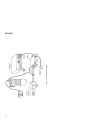
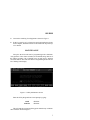
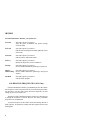
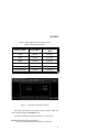
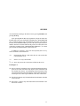
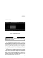
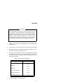
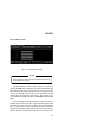
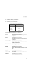
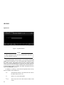
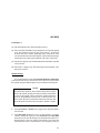
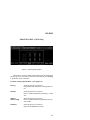
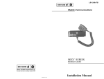
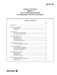
LBI-38898
Mobile Communications
EDACS-2 UTILITY
PROGRAMMING
Maintenance Manual
LBI-38898
TABLE OF CONTENTS
Page
INTRODUCTION ................................................................
TRACKING DATA ......................................................
SYSTEM HOOK-UP (PCS Only)................................
System Hook-Up Procedure ..................................
3
3
4
5
MAINTENANCE.................................................................
7
CALIBRATION FREQUENCIES (PCS Only)...................
8
CALIBRATION (PCS Only) ...............................................
TX POWER...................................................................
TX Power Settings .................................................
TX MODULATION .....................................................
TX Modulation Settings.........................................
DATA MODULATION................................................
Data Modulation Settings ......................................
SQUELCH.....................................................................
Squelch Settings.....................................................
10
10
12
15
16
19
20
22
23
TRACKING DATA (PCS Only) .........................................
25
FEATURES (Includes MDR, MDX And PCS)...................
26
Copyright© June 1993, Ericsson GE Mobile Communications Inc.
2
LBI-38898
INTRODUCTION
This manual describes the operation of the EDACS-2 Utility Software that is provided with TQ-3346/TQ-3373 Programming software.
The Utility Software is used to make Final Transmitter and Receiver
Alignments on the Dual Format PCS portable radio. This manual describes how to calibrate and adjust the Tracking Data in the PCS radio
using the Utility Program. It is also used for changing the Feature Authorization on the Dual Format MDR and MDX mobile radios along with the
Dual Format PCS portable radio.
TRACKING DATA (PCS Only)
Tracking Data establishes individual radio parameters and tailors the
operation of the unit across the band. The four parameters include High
and Low RF Power, Modulation Level, Data Modulation and Receiver
Squelch opening. This data is programmed into the personality EEPROM
at the factory after the Front and Rear Assemblies are joined together.
Tracking data values are not used for each individual channel. Instead, the 806-824 MHz band is divided into 3 band segments and the
851-869 MHz band is also divided into 3 band segments. All channels
within each band segment use the same tracking values.
Tracking Data should not normally be altered; however, it may be
necessary to reprogram some of the values after aligning circuitry, or
replacing modules or other components which obsolete the previously
programmed values. Typical starting values for each parameter are listed
in Table 1.
Digital values stored for the POWER SET analog voltage are one
example of tracking information. As no two transmitter stages are exactly
matched, the POWER SET DC voltage will be slightly different with any
two radios to produce the same power output. Tracking Data allows the
microprocessor to tailor the POWER SET line for the RF stage difference
from unit-to-unit and across the band.
3
LBI-38898
SYSTEM HOOK-UP (PCS Only)
Connect all peripheral equipment to your computer prior to configuring the PC Programming Software items. Remember to refer to the
operating manuals of each device for correct installation procedures.
If your system is already established, check to see that you have all
the equipment necessary to execute the program. Isolate all cables connecting the computer to devices to prevent tangling, interference and
damage.
Table 1 - Tracking Data Parameters
PARAMETERS
TYPICAL HEX VALUES
Squelch Openings
(All Bands)
B3
NORMAL
TX BAND
LOW
MEDIUM
HIGH
806-813 MHz 813-821 MHz 821-824 MHz
Power-High
7E
7F
7F
Power-Low
50
52
53
TX Modulation
27
26
1B
Data Modulation
28
27
1D
PARAMETERS
TYPICAL HEX VALUES
TALKAROUND
LOW
MEDIUM
HIGH
TX BAND
851-858 MHz 858-866 MHz 866-869 MHz
Power-High
76
78
72
Power-Low
54
54
57
TX Modulation
2D
2B
20
Data Modulation
**
**
**
** NOT USED
4
LBI-38898
System Hook-Up Procedure (Refer to Figure 1)
1.
Locate a serial port on your computer. This port will usually be
located at the rear of the computer. However, since this is dependent
upon the design of your computer, refer to the computer operator’s
manual for directions.
The IBM PC/XT/AT systems support up to two serial ports. There
are two physical standards for the serial port configurations of personal computers. The first standard is a 25 pin RS-232 output that has
a DB-25 male connector at the computer. The other standard has a
DB-9 male connector at the computer (used on IBM-AT and many
portable lap-top computers). The PC Interface Module, like most data
communication equipment, uses a standard RS-232, DB-25, female
connector. If your computer uses a DB-9 connector, you will need to
purchase a DB-9/DB-25 adaptor cable from your local computer
dealer.
2.
Please note the Utility Software only communicates with the radio
and its interface through the serial port designated as COM1 or
COM2. Your computer references will assist you in determining
which serial port has been so designated. Once located, examine the
keyed plug on the RS-232 cable for the correct keyed end and insert
it carefully into the appropriate serial port on the computer.
3.
The other end of the RS-232 cable should now be connected to the
computer receptacle on the PC Interface Module (TQ-3310 or TQ3370). Check carefully to ensure that plugs are fully seated in the
receptacle and, if retaining screws are included, that they are carefully
tightened to firmly hold the plug in place. Should the plug not seat
correctly to its receptacle, remove the plug and examine the pins to
determine if the proper plug was inserted and to detemine if pins are
aligned and undamaged. Damaged pins and broken connections will
cause the PC Programming Software to fail.
4.
Position the radio on the work area in a convenient place. The
Programming Cable (TQ-3336) connects the radio to the Ribbon
Cable (TQ-0652) as shown in Figure 1. The UDC (Universal Device
Connector) connects to the side of the radio and the DB 25 pin
connector connects to the ribbon cable. Ensure that power is applied
to the radio before using the Utility Program.
5
6
Figure 1 - Test Equipment Setup
(TYPICAL)
LBI-38898
LBI-38898
5.
Connect the remaining Test Equipment as shown in Figure 1.
6.
If the TQ-3346/TQ-3373 software has not been installed previously
on the computer, install the software as described in the TQ-3346/TQ3373 manual.
MAINTENANCE
First place the PCS radio into PC programming mode. Simultaneously push one of the volume switches (UP or DOWN) along with one of
the channel switches (UP or DOWN), turn on radio power, and then
release the buttons. The radio will enter PC Programming mode with "PC
Pro" flashing in the display.
Figure 2 - Utiltity Maintenance Screen
Enter the Utility Program from a DOS prompt by typing:
cd\GE
<ENTER>
MAINT2
<ENTER>
This will start the program and bring up the Introductory or Maintenance Window shown in Figure 2.
7
LBI-38898
From the Maintenance Window, your options are:
F1-Calib
Select this option if you want to:
Align the power, modulation and squelch settings
across the band.
F2-Track
Select this option if you want to:
Edit the radio tracking data and then update the values
in the radio.
F3-Featur
Select this option if you want to:
Edit the Feature Authorization data.
F4-Freq
Select this option if you want to:
Modify the frequencies used for calibration.
F9-Help
Select this option if you want to:
Receive further information pertaining to a field area.
Shift F9
Window Help
Select this option if you want to:
Receive further information pertaining to the present
window.
F10-Back
Select this option if you want to:
Exit the Utility Program.
CALIBRATION FREQUENCIES (PCS Only)
From the Maintenance Window, press F4 Freq to show the calibration frequencies. These frequencies will be used later during the calibration procedure. You may want to write down these frequencies for later
setting up your service monitor, etc.
The purpose of the Calibration Frequency window is to allow the user
to modify the frequencies if desired. However, the factory calibration
frequencies are recommended.
As shown in Table 2, the PCS radio divides the tracking data into 6
band segments. All frequencies within each band segment use the same
tracking data.
8
LBI-38898
Table 2 - Band Segment Fequency Ranges And
Factory Calibration Frequencies
Frequency Band
Range (MHz)
Factory Calibration
(MHz)
LOW
806-813
806.0125
MID
813-821
813.0125
HIGH
821-824
824.0125
LOW Talkaround
851-858
851.0125
MID Talkaround
858-866
858.0125
HIGH Talkaround
866-869
869.0125
Figure 3 - Calibration Frequencies Window
All fields represent the TX frequency and are numeric. Make the
desired changes and press F10 Back to exit.
From the Calibration Frequencies Window, your options are:
F9-Help Select this option if you want to:
Receive further information pertaining to a field area.
9
LBI-38898
Shift F9
Window Help
Select this option if you want to:
Receive further information pertaining to the present
window.
F10-Back
Select this option if you want to:
Return to the Maintenance Screen.
CALIBRATION (PCS Only)
TX POWER
Figure 4 - TX Power Window
NOTE
While adjusting the radio, DO NOT disconnect the radio from
the PC interface at any time.
The TX High/Lo Power Window, shown in Figure 4, is accessed by
selecting F1 Calib from the Maintenance Screen and then F1 Next or F2
Prev until the window appears. This window allows the user to align the
high power setting across the band. There are six input fields on this
screen: Low, Mid, High, Talk Around Low, Talk Around Mid, and Talk
Around High. The frequencies represented by these settings can be
10
LBI-38898
viewed/edited by returning to the main screen by pressing F10 Back, and
pressing F4 Freq.
Upon pressing F4 Tx On, the programmer will put the radio into
transmit mode. The screen will display a blinking field, "TRANSMITTER
ON", to indicate that the radio is transmitting. The radio will remain in
transmit mode until F4 Tx Off is pressed, or the timeout period (about 2
minutes) has been exceeded. If the timeout period is exceeded, the screen
will display a blinking field, "TRANSMITTER TIMEOUT", for a short
period of time and the transmitter will be turned off.
In addition to entering a value from the keyboard, there are key
actions available as described below:
<+>
Increments the field by 1 and writes the new value to the radio
if the transmitter is on.
<->
Same as <+> only it decrements.
↑↓→← Arrow keys move the cursor between fields on the screen.
From Figure 3:
(1) This is a numeric field that is used to align the transmit high and low
power levels. This field will accept any hex value from 00-FF and
any decimal value from 0 - 255, depending on the current state of the
screen (Hexadecimal or decimal) displays. The bar indicator changes
with and provides a direct representation of the value of this field.
(2) This field is a display only field and indicates the minimum value that
can be selected.
(3) This field is a display only field and indicates the maximum value
that can be selected.
11
LBI-38898
TX Power Settings
High Power Settings
1.
The "Tx High Power Calibration" window should be on the screen.
If this window is not on the screen, then use the F1 Next or F2 Prev
keys to toggle to the correct window.
2.
Press F4 Tx On to key the transmitter.
3.
Measure the transmitter power output.
4.
With the Low Frequency value highlighted, increment or decrement
the current value (Hex or Decimal) until the specified window for
power is reached. See Table 3.
5.
Measure the total radio current. Current should be less than the high
power current specification given in the table. The tracking data for
each band segment will be updated with the displayed value upon
exiting the calibration application (pressing F10 to exit and F1 to
update tracking data).
6.
Press the F4 Tx Off to unkey the transmitter.
7.
Repeat this procedure for the remaining 5 frequencies.
12
LBI-38898
Table 3 - High And Low Power Specifiations
HIGH POWER
FREQUENCY
LOW POWER
Power
(Watts)
I(Amps)
Power
(Watts)
I(Amps)
TX Low
3.2 ±0.1
<2.0
1.1 ±0.1
<1.3
TX Mid
3.2 ±0.1
<2.0
1.1 ±0.1
<1.3
TX High
3.2 ±0.1
<2.0
1.1 ±0.1
<1.3
TX Low
Talkaround
2.5 ±0.1
<2.0
1.1 ±0.1
<1.3
TX Mid
Talkaround
2.5 ±0.1
<2.0
1.1 ±0.1
<1.3
TX High
Talkaround
2.5 ±0.1
<2.0
1.1 ±0.1
<1.3
Low Power Settings
1.
Using the F1 Next or F2 Prev keys, toggle to the "Tx Low Power
Calibration" window.
2.
Press F4 Tx On to key the transmitter.
3.
Measure the transmitter power output.
4.
With the Low Frequency value highlighted, increment or decrement
the current value (Hex or Decimal) until the specified window for
power is reached. See Table 3.
5.
Measure the total radio current. Current should be less than the low
power current specification given in the table. The tracking data for
each band segment will be updated with the displayed value upon
exiting the calibration application (pressing F10 to exit and F1 to
update tracking data).
6.
Press the F4 Tx Off to unkey the transmitter.
7.
Repeat this procedure for the remaining 5 frequencies.
13
LBI-38898
From TX Power window, your options are:
F1-Next
Select this option if you want to:
Advance the screen to the next setting which can
be adjusted.
F2-Prev
Select this option if you want to:
Return the screen to the previous setting which can
be adjusted.
F3-Decimal/Hex
Select this option if you want to:
Toggle the input fields on the screen between
decimal and hexadecimal.
F4-Tx On/Tx Off
Select this option if you want to:
Key or unkey the radio.
F9-Help
Select this option if you want to:
Receive further information pertaining to a field
area.
Shift F9
Window Help
Select this option if you want to:
Receive further information pertaining to the present window.
F10-Back
Select this option if you want to:
Return to the Maintenance Screen.
14
LBI-38898
TX MODULATION
Figure 5 - TX Modulation Window
NOTE
While adjusting the radio, DO NOT disconnect the radio from
the PC interface at any time.
The TX Modulation Window, shown in Figure 5, is accessed by
selecting F1 Calib from the Maintenance Screen and then F1 Next or F2
Prev until the window appears. This window allows the user to align the
Transmit Modulation setting across the band. There are six input fields on
this screen: Low, Mid, High, Talk Around Low, Talk Around Mid, and
Talk Around High. The frequencies represented by these settings can be
viewed/edited by returning to the main screen (F10 Back), and pressing
F4 Freq.
Upon pressing F4 Tx On, the programmer will put the radio into
transmit mode. The screen will display a blinking field, "TRANSMITTER
ON", to indicate that the radio is transmitting. The radio will remain in
transmit mode until F4 Tx Off is pressed, or the timeout period (about 2
minutes) has been exceeded. If the timeout period is exceeded, the screen
will display a blinking field, "TRANSMITTER TIMEOUT", for a short
period of time and the transmitter will be turned off.
15
LBI-38898
In addition to entering a value from the keyboard, there are key
actions available as described below:
<+>
Increments the field by 1 and writes the new value to
the radio if the transmitter is on.
<->
Same as <+> only it decrements.
↑↓→←
Arrow keys move the cursor between fields on the
screen.
From Figure 5:
(1) This is a numeric field that is used to set the Transmit Modulation
level. This field will accept any hex value from 00 - 3F and any digital
value from 0 - 63, depending on the current state of the screen
(Hexadecimal or decimal) displays. The bar indicator changes with
and provides a direct representation of the value of this field.
(2) This field is a display only field and indicates the minimum value that
can be selected.
(3) This field is a display only field and indicates the maximum value
that can be selected.
TX Modulation Settings
1.
16
Feed a 200 mV rms, 1 kHz tone into the TX Audio Jacks on the
TQ-0613 Test Box.
LBI-38898
NOTE
The MIC HI input line to the PCS is also the RX DATA line from
the computer. To allow simultaneous communication with the
computer while feeding in a 1 kHz tone, the audio generator
impedance must be 600 ohms or greater. Insert a resistor in series
with the generator output if necessary, i.e. a 560 ohm resistor
when using a 50 ohm generator. Also, higher audio signal levels
exceeding 200 mV rms may confuse the radio as being data.
2.
With the Low Frequency value highlighted, press F4 Tx On to key
the transmitter.
3.
The 1 kHz tone will be summed with a 75 Hz low speed data signal.
4.
Measure the deviation. The Modulation Monitor should be set for 15
kHz low pass filter and no high pass filter.
5.
Increment or decrement the value (hex or digital) until the deviation
specifiations are met. See Table 4. The deviation test window is 0.20
kHz wide. Each step is typically 0.14 kHz, depending on the VCO
modulation sensitivity.
Table 4 - TX Deviation Specifications
FREQUENCY
6.
DEVIATION (kHz)
TX Low
4.5 ±0.1
TX Mid
4.5 ±0.1
TX High
3.6 ±0.1
TX Low Talkaround
4.5 ±0.1
TX Mid Talkaround
4.5 ±0.1
TX High Talkaround
3.6 ±0.1
Press F4 Tx Off to key the transmitter.
17
LBI-38898
7.
Repeat steps 4-6 for each frequency.
From TX Modulation Window, your options are:
F1-Next
Select this option if you want to:
Advance the screen to the next setting which can
be adjusted.
F2-Prev
Select this option if you want to:
Return the screen to the previous setting which can
be adjusted.
F3-Decimal/Hex
Select this option if you want to:
Toggle the input fields on the screen between
decimal and hexadecimal.
F4-Tx On/Tx Off
Select this option if you want to:
Key or unkey the radio.
F9-Help
Select this option if you want to:
Receive further information pertaining to a field
area.
Shift F9
Window Help
Select this option if you want to:
Receive further information pertaining to the present window.
F10-Back
Select this option if you want to:
Return to the Maintenance Screen.
18
LBI-38898
DATA MODULATION
Figure 6 - Data Modulation Window
NOTE
While adjusting the radio, DO NOT disconnect the radio from
the PC interface at any time.
The Data Modulation Window, shown in Figure 6, is accessed by
selecting F1 Calib from the Maintenance Screen and then F1 Next or F2
Prev until the window appears. This window allows the user to align the
data modulation setting across the band. There are six input fields on this
screen: Low, Mid, High, Talk Around Low, Talk Around Mid, and Talk
Around High. The frequencies represented by these settings can be
viewed/edited by returning to the main screen F10 Back, and pressing F4
Freq.
Upon pressing F4 Tx On, the programmer will put the radio into
transmit mode and instruct the radio to begin transmitting random 9600
baud data. The screen will display a blinking field "TRANSMITTER
ON", to indicate that the radio is transmitting. The radio will remain in
transmit mode until F4 Tx Off is pressed, or the timeout period (about 2
minutes) has been exceeded. If the timeout period is exceeded, the screen
19
LBI-38898
will display a blinking field, "TRANSMITTER TIMEOUT", for a short
period of time.
In addition to entering a value from the keyboard, there are key
actions available as described below:
<+>
Increments the field by 1 and writes the new value to
the radio if the transmitter is on.
<->
Same as <+> only it decrements.
↑↓→←
Arrow keys move the cursor between fields on the
screen.
From Figure 6:
(1) This is a numeric field that is used to align the data modulation level.
This field will accept any hex value from 00 - 3F and any decimal
value from 0 - 63, depending on the current state of the screen
(Hexadecimal or decimal) displays. The bar indicator changes with
and provides a direct representation of the value of this field.
Data Modulation Settings
NOTE
The personality map has data deviation bytes reserved for TX
LOW TALKAROUND, TX MID TALKAROUND and TX
HIGH TALKAROUND. These EEPROMS locations are presently not used and do not have to be programmed.
1.
From the "Data Modulation" window and with Low Frequency
highlighted, press F4 Tx On to key the transmitter. The radio will
begin transmitting random 9600 baud data.
2.
Measure the data deviation. The Modulation Monitor should be set
for 15 kHz low pass filter and no high pass filter.
3.
Increment or decrement the current value (Hex or Decimal) until the
specified window for data deviation is reached. See Table 5.
20
LBI-38898
4.
Press F4 Tx Off to key the transmitter.
5.
Repeat steps 2-6 for each frequency.
Table 5 - Data Deviation Specifications
FREQUENCY
DEVIATION (kHz)
TX Low
3.0 ±0.1
TX Mid
3.0 ±0.1
TX High
2.4 ±0.1
From Data Modulation Window, your options are:
F1-Next
Select this option if you want to:
Advance the screen to the next setting which can
be adjusted.
F2-Prev
Select this option if you want to:
Return the screen to the previous setting which can
be adjusted.
F3-Decimal/Hex
Select this option if you want to:
Toggle the input fields on the screen between
decimal and hexadecimal.
F4-Tx On/Tx Off
Select this option if you want to:
Key or unkey the radio.
F9-Help
Select this option if you want to:
Receive further information pertaining to a field
area.
Shift F9
Window Help
Select this option if you want to:
Receive further information pertaining to the present window.
F10-Back
Select this option if you want to:
Return to the Maintenance Screen.
21
LBI-38898
SQUELCH
Figure 7 - Squelch Window
NOTE
While adjusting the radio, DO NOT disconnect the radio from
the PC interface at any time.
The Squelch Window, shown in Figure 7, is accessed by selecting F1
Calib from the Maintenance Screen and then F1 Next or F2 Prev until
the window appears. This window allows the user to align the squelch
setting. Upon pressing F4 Rx On, the programmer will put the radio into
receive mode. The screen will display a blinking field, "RECEIVER ON",
to indicate that the radio is receiving. The radio will remain in receive
mode until F4 Rx Off is pressed.
In addition to entering a value from the keyboard, there are key
actions available as described below:
22
<+>
Increments the field by 1 and writes the new value to
the radio if the receiver is on.
<->
Same as <+> only it decrements.
↑↓→←
Arrow keys move the cursor between fields on the
screen.
LBI-38898
From Figure 7:
(1) This field indicates the current band split selected.
(2) This is a numeric field that is used to align the receive squelch opening
level. This field will accept any hex value from 90 - E2 and any
decimal value from 144-226, depending on the current state of the
screen (Hexadecimal or decimal) displays. The bar indicator changes
with and provides a direct representation of the value of this field.
(3) This field is a display only field and indicates the minimum value that
can be selected.
(4) This field is a display only field and indicates the maximum value
that can be selected.
Squelch Settings
It is recommended to use the Conventional Method Of Adjustment
as described in the Service Section, but if it becomes necessary to adjust
the squelch using the Utility Program, keep in mind the following note:
NOTE
In normal radio operation, when software detects the first quick
burst of the squelch opening, the hysteresis adds a fixed number
of steps to the squelch value to loosen the squelch and keep it
open. PC Programming mode does not use the hysteresis software routine. Therefore, without this routine, the test below must
detect the point when the audio just begins to bubble or chatter.
1.
Using the F1 Next or F2 Prev keys, toggle to the "Squelch Calibration" window.
2.
The Chan Field should read "Low". Use the TAB key as a toggle
switch to change the frequency of the Chan field. The Chan Field
allows the user to select the frequency on which the radio will receive.
Note that there is only one squelch value which is used across the
entire band. For non-T/A selections, the receive frequency will be 45
23
LBI-38898
MHz above the specified TX frequency. For Talkaround selections,
the receive frequency will be the same as the specified TX frequency.
3.
Press F4 to toggle the RX audio on.
4.
Move down to the Value Field and change the value to "E2 for hex
or 226 for decimal". This will open the receiver squelch.
5.
With the RF generator at -117.0 dBm, modulated with a 1 kHz tone
at 3 kHz deviation, reduce generator RF level until 8-10 dB SINAD
is found across the RX AUDIO jacks on the TQ-0613 Test Box.
6.
Decrement the value field until the RX audio turns completely off.
Increment the value field one step and check for occasional bursts of
receiver audio. Repeat until the point is reached that the audio just
begins to chatter.
From the Squelch Window, your options are:
F1-Next
Select this option if you want to:
Advance the screen to the next setting which can
be adjusted.
F2-Prev
Select this option if you want to:
Return the screen to the previous setting which can
be adjusted.
F3-Decimal/Hex
Select this option if you want to:
Toggle the input fields on the screen between
decimal and hexadecimal.
F4-Rx On/Rx Off
Select this option if you want to:
Put the radio in or out of receive mode.
F9-Help
Select this option if you want to:
Receive further information pertaining to a field
area.
Shift F9
Window Help
Select this option if you want to:
Receive further information pertaining to the present window.
F10-Back
Select this option if you want to:
Return to the Maintenance Screen.
24
LBI-38898
TRACKING DATA (PCS Only)
Figure 8 - Tracking Data Window
This window is used to edit the radio tracking data (in hexadecimal
format only). Once the desired values have been entered, press F5 Prog
to update the values in the radio.
From the Tracking Data Window, your options are:
F5-Prog
Select this option if you want to:
Program the radio with the new tracking data values.
F9-Help
Select this option if you want to:
Receive further information pertaining to a field
area.
Shift F9
Window Help
Select this option if you want to:
Receive further information pertaining to the present window.
F10-Back
Select this option if you want to:
Return to the Maintenance Screen.
25
LBI-38898
FEATURES (Includes MDR, MDX And PCS)
Figure 9 - Features Window
WARNING
Changing the data on this screen can disable the radio.
The Feature Authorization Window, shown in Figure 9, is accessed
by selecting F3 Featur from the Maintenance Screen. This window is
used to Read, Write or Edit the Feature Authorization Data in the radio.
Highlight one of these options and press <CR>. After Reading the data
from the radio, the Radio Serial Number and Type, along with the
Communication Port is displayed on the screen.
From the Features Window, your options are:
F10-Back
26
Select this option if you want to:
Return to the Maintenance Screen.
LBI-38898
NOTES
27
Printed in U.S.A.