1
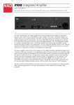
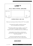
XX
POWER AMPLIFIER
INSTRUCTIONS FOR USE
Thank you for purchasing the Musical Fidelity A5 CR Power amplifier.
Used properly and carefully, it should give many years of outstanding musical
reproduction.
Aesthetically, the A5 CR Power amplifier is a perfect match for the
A5 CR Pre-amplifier and A5 CD player.
Together they form one of the finest hi-fi systems available.
Dust regularly with a soft duster or soft brush, but be careful when using cleaning
or polishing agents - they may harm the surface finish.
If you have any questions about your audio system,
please consult your dealer who is there to help and advise.
Issue 1 : November 2004
A5 CR Power Amplifier
Instructions for use
Page 1 of 7
SAFETY INFORMATION
IMPORTANT! (U.K. only)
This unit is supplied in the U.K. with a mains lead fitted with a moulded 13 amp plug. If, for any
reason, you need to cut off the plug, please remove the fuse holder and dispose of the plug safely,
out of reach of children. It must not be plugged into a mains outlet.
The wires in the mains lead supplied with this appliance are coloured in accordance with the
following code:
Green and yellow..............Earth
Blue................................Neutral
Brown.................................Live
WARNING - This appliance must be earthed
As the colours of the wires of the mains lead of this appliance may not correspond with the coloured
markings identifying the terminals in your plug, proceed as follows:
The wire which is coloured green-and-yellow must be connected to the terminal in the plug which is
marked with the letter E or coloured green or green-and-yellow, or by the earth symbol:
The wire which is coloured brown must be connected to the terminal which is marked with the letter
L or coloured red.
The wire which is coloured blue must be connected to the terminal which is marked with the letter N
or coloured black.
If connecting to a BS1363 plug, a 13 amp fuse must be used.
WARNING:
The A5 is a powerful amplifier and must necessarily supply high voltages
through the loudspeaker terminals. Therefore, to avoid any possibility of an
electric shock DO NOT TOUCH THE SPEAKER TERMINALS when the unit
is being used. To comply with BSEN60065 safety regulations, the 4mm
“banana” plug holes have been fitted with plastic blanking pieces. Removal of
these will invalidate any electrical safety approval of this product.
WARNING:
Any modifications to this product not expressly approved by Musical Fidelity
who is the party responsible for standards compliance could void the user’s
authority to operate this equipment.
Issue 1 : November 2004
A5 CR Power Amplifier
Instructions for use
Page 2 of 7
GENERAL ADVICE
INSTALLATION PRECAUTIONS and USER INFORMATION
Your new A5 CR Power amplifier is designed and built to provide trouble-free performance, but as
with all electronic devices it is necessary to observe a few precautions:
Heed all warnings shown on the back of the product.
Only connect the A5 CR Power to a mains outlet having the same voltage as marked at the back of the
unit.
Always ensure that when disconnecting and reconnecting your audio equipment the mains supply is
switched off.
Position the mains lead and signal interconnects where they are not likely to be walked on or trapped
by items placed on them.
Do not use near water, or place water-filled containers on the amplifier, for example, a flower vase
or potted plants. If water does spill inside, immediately pull out the mains plug from the wall
socket and inform your dealer, who should then check the unit before further use. Entry of
liquid into the amplifier is dangerous, and may cause electric shock or fire hazard.
Do not place the unit near direct heat sources such as radiators, direct sunlight or other equipment.
Do not remove any covers or try to gain access to the inside. There are no internal adjustments or
fuses you can replace yourself. Refer all service work to an authorised Musical Fidelity agent.
Note: Unauthorised opening of the equipment will invalidate any warranty claim.
Dust regularly with a soft cloth or soft brush but be careful when using cleaning or polishing agents they may harm the surface finish.
The electronics in modern hi-fi equipment is complex and may, therefore, be adversely affected or
damaged by lightning. For protection of your audio system during electrical storms, remove the
mains plugs and disconnect any aerial lead.
If after-sales service is required, to help your dealer identify the A5 CR Power amplifier please quote
the serial number located on the rear panel of the unit.
RADIO FREQUENCY INTERFERENCE (R.F.I)
This product has been tested to ensure that its operation is not adversely affected by normal
background levels of R.F.I., and that it does not itself generate excessive amounts of interference.
However, if a problem persists, please contact your Musical Fidelity agent.
Issue 1 : November 2004
A5 CR Power Amplifier
Instructions for use
Page 3 of 7
CONNECTIONS and FACILITIES
INPUT B indicator LED
POWER-on indicator LED
POWER
on / off switch
MUTE
indicator LED
INPUT A
indicator LED
Input selector
button (see page 5)
FRONT PANEL
REAR PANEL
IEC mains power inlet socket
RIGHT SPEAKER
OUTPUT terminals
Issue 1 : November 2004
loop-OUTPUT
sockets
- see page 5
INPUT sockets
- see page 5
A5 CR Power Amplifier
LEFT SPEAKER
OUTPUT terminals
Instructions for use
Page 4 of 7
CONNECTIONS and OPERATION
All input, output and power connections should
be made with the mains power switched OFF.
If in doubt about bi-amplification, please
contact your dealer for advice.
INPUT CONNECTIONS
LOUDSPEAKER CONNECTIONS
The A5 CR Power amplifier can be used with any
preamplifier or line level source which has a
volume control. We highly recommend the
matching A5 CR Preamplifier available from
Musical Fidelity.
Connect your loudspeakers to either of the two
pairs of loudspeaker terminals situated on the
back panel marked as LEFT and RIGHT
SPEAKER OUTPUT. The wiring must be
“in phase”, namely, the + and - terminals must
be connected to the left and right speakers the
same way round.
Two stereo pairs of RCA audio input sockets
marked “A” and “B” on the rear panel allow a
choice between either of these input sources.
Simultaneous mixed A and B operation is not
possible.
Using good quality co-axial audio leads,
connect the left and right outputs from your preamp or other line level source to either or both
A and B inputs.
Whichever input is chosen, a fixed “line level”
audio output from the selected source is
available from the adjacent OUTPUT RCA
sockets for onward connection to another
amplifier. This is to allow for “biamplification” (see below).
Note: - the combined load impedance must not
be less than 4 ohms.
BEFORE SWITCHING ON. . . . .
Plug the accessory IEC mains lead into the rear
panel socket, then the other end into a
convenient wall outlet.
Turn the volume control on your pre-amplifier
to minimum, and switch on its power.
OPERATION
Press the POWER switch button on the lefthand end of the front panel on the A5 CR Power.
BI-AMPLIFICATION
The A5’s RCA OUTPUT sockets allow “biamplification” of a speaker system using
suitable external amplifiers and crossover
networks. This enables the speaker drive units
to be powered separately, giving noticeable
improvement in clarity, imaging and bass
weight.
The blue POWER LED will light to confirm
that the unit is ready for use.
In this arrangement, typically one A5 CR Power
amplifier is used to drive the “tweeter” (high
frequencies), and another to drive the “woofer”
(low frequencies) of each loudspeaker
enclosure. Thus, two A5s would be needed for
a stereo pair.
Select the required audio input source A or B
by pressing the selector button on the righthand end of the front panel. Now increase the
volume control on your pre-amplifier to obtain
the preferred sound level.
However, for a few seconds no sound will be
heard from your speakers, and the red mute
indicator LED near the button will be lit,
confirming initial mute action.
(continued . . . )
Issue 1 : November 2004
A5 CR Power Amplifier
Instructions for use
Page 5 of 7
PROBLEMS ?
Basic problem-solving with an amplifier is similar to troubleshooting other electrical or electronic
equipment. Always check the most obvious possible causes first, such as the following examples:
Problem
Probable Cause
Remedy
No power when POWER
button is pressed
Mains power plug is not fully
inserted into rear socket
Plug in securely
No sound
Tape monitor function has been Switch off tape monitor
selected on the pre-amplifier
Wrong connections between
input source and the A5 Power
Check audio input lead
connections
Speakers not connected, or
incorrectly wired
Check speaker cables
Sound is not precise, lacking in Speakers are connected out of
bass and stereo image
phase, i.e., connections to one
speaker (+ and -) are reversed
Ensure speakers are connected
correctly
Hum
Insert plug securely
Audio connector plug not fully
pushed in
If none of these actions effect a cure, please contact your dealer, or an authorised Musical Fidelity
service agent. Remember, never open the case of the A5 CR Power amplifier yourself, as this will
invalidate the guarantee.
Issue 1 : November 2004
A5 CR Power Amplifier
Instructions for use
Page 6 of 7
A5 CR
.SPECIFICATIONS.
POWER AMPLIFIER
Output :
Power :
255 Watts per channel into 8 Ohms (24dBW),
416 Watts per channel into 4 Ohms
45.2 Volts 20Hz to 20kHz
118.8 Volts
200 Amps
170
8
Voltage, RMS :
Voltage, Peak-to-peak :
Current peak-to-peak
Damping factor :
Output devices per channel :
Line inputs :
Total harmonic distortion + noise,
Signal / noise ratio
Input sensitivity for 255 Watts into 8 Ohms
Input impedance
Channel separation
Frequency response
Inputs :
“A”
“B”
< 0.01% 20Hz to 20kHz
> 109dB ‘A’-weighted
1.5V
100k Ohms
> 90dB typical
10Hz to 100kHz, +0, -1.5 dB
1 pair line level RCA connectors
1 pair line level RCA connectors
Outputs :
2 amplifier channels via 2 pairs per channel binding posts
1 pair RCA loop output sockets
Power requirement :
100 / 115 / 230Volts AC 50 / 60Hz (factory pre-set),
750 Watts maximum into 8 Ohms, 70 Watts idle
Weight :
19.1 kg, 42.1 lbs unit only, unboxed
23.75 kg, 52.4 lbs in shipping carton
Dimensions :
440 mm,
125 mm,
400 mm,
Standard accessories :
IEC type mains lead (10-Amp type)
17.3 inches wide
4.9 inches high including feet
15.75 inches deep including terminals
Musical Fidelity reserves the right to make improvements which
may result in specification or feature changes without notice.
Issue 1 : November 2004
A5 CR Power Amplifier
Instructions for use
Page 7 of 7