1
Operators
Manual
[CRAFTSMAN"
I
7.8 Horsepower
3000 PSI
2.5 GPM
HIGH PRESSURE WASHER
CLEANING SYSTEM
Model No. 580.768050
HOURS: Mon.- FH. 8 a.m. to 5 p.m. (CST)
CAUTION:
Before using this product, read this
manual and follow all its Safety Rules
and Operating Instructions.
Sears, Roebuck and Co., Hoffman Estates, IL 60179
Visit our Craftsman website: www.sears.com/craftsman
Part No. B3604 Draft 0 (2/2/99) printed in the U.S.A.
•
•
•
•
•
Safety
Assembly
Operation
Maintenance
Parts
Warranty ................................
Safety Rules ...........................
2
2--3
Assembly ...............................
Operation .............................
Maintenance .........................
4
5-9
10-15
Storage ................................
Troubleshooting .........................
Replacements parts ....................
Emission Control
Warranty Statement ....................
How to order parts and
request service ....................
16
LIMITED ONE YEAR WARRANTY ON CRAFTSMAN
CLEANING
17
19--27
28-29
Backpage
SYSTEM
For one year from the date of purchase, when this Craftsman Cleaning System is maintained and operated
accordingto the instructionsin the owner's manual, Sears will repair, free of charge, any defect in materialand
workmanship.
If this washer is used for commercialpurposes, this warranty applies for only 90 days from the date oi
purchase. If this cleaning system is used for rental purposes,this warranty applies for only 30 days after date
of purchase.
LIMITED TWO YEAR WARRANTY ON CRAFTSMAN
ENGINE
For two years from the date of purchase, when this Craftsman engine is maintained and operated accordingto
the instructionson the owner's manual, Sears will repair, free of charge, any defect in matadal and
workmanship.
If the Craftsman engine is used for commercial or rental purposes, this warranty applies for only one year from
the date of purchase.
•....
This warranty does not cover:.
!
• Expendable items such as spark plugs or air filters, which become worn _udng norma! use_
• Repairs necessary because of operator abuse or negligence, includingdamage resultingfrom no water
being suppliedto pump or failure to maintain the equipment according to the instructionscontained in the
owner's manual.
WARRANTY SERVICE IS AVAILABLE BY RETURNING THE HIGH CLEANING SYSTEM TO THE.
NEAREST SEARS SERVICE CENTER OR DEALER IN THE UNITED STATES.
i _
_.
This warranty gives you specificlegal dghts and you may also have other dghts, which vary_m.mstate.t0 state.,
Sears, Roebuck and Co., Dept. 81TWA, Hoffman Estates, IL 60179 •
Engine exhaust gases contain DEADLY carbon
monoxidegas. This dangerous gas, if breathed in
sufficientconcentrations,can cause
unconsciousnessor even death. Operate this
equipment only in the open air where adequate
ventilationis available.
•
,_
CAU'FION:
usingthis
product,read
this
manual andBefore
follow all
Safety Rules
and
Operating Instructions.
A
DANGER: When transporting,setting up,
adjustingor makingrepairs to your cleaning
system,always disconnectthe spark plug wire
and place if where if cannot contact the spark
plug to prevent accidental starting.
•
2
Gasoline is highly FLAMMABLE and its vapors are
EXPLOSIVE. Do not permit smoking,open flames,
sparks or heat in the vicinitywhile handling
gasoline. Avoid spillinggasoline on a hot engine.
Allow unitto cool for 2 minutes before refueling.
Comply with all laws regulatingstorage and
handlingof gasoline.
Locate this cleaning system in areas away from
combustiblematedals, combustible fumes or dust.
• The high pressure equipmentis designed to be
used with Sears authorized parts only. If you use
this equipment with parts that do not comply with
minimumspecifications,the user assumes all risks
and liabilities.
•
Some chemicalsor detergentsmay be harmful if
inhaledor ingested,causing severe nausea,
faintingor poisoning.The harmfulelements may
cause propertydamage or severe injury.
•
Do not allowCHILDREN to operate the cleaning
system at any time.
Never move the machineby pullingon the high
pressure hose. Use the handle providedon the
top of the unit.
Always be certainthe spray gun, nozzles and
accessories are correctlyattached.
Never use a spray gun which does not have a
trigger lock or triggerguard in place and in
working order.
Use a respirator or mask whenever there is a
chance that vapors may be inhaled. Read all
instructionswith the mask so you are certainthe
mask will providethe necessary protectionagainst
inhaling harmful vapors.
Operate engine only at govemed speed. Running
the engine at excessivespeeds increases the
hazard of personalinjury. Do not tamper with parts
which may increase or decrease the governed
speed.
•
Do not wear looseclothing,jewelry or anything
that may be caught in the starter or other rotating
parts.
•
Before startingthe cleaning system in cold
weather, check all parts of the equipment and be
sure ice has not formed there.
•
Units with broken or missing parts, or without
protectivehousingor covers should NEVER be
operated.
The muffler and air cleaner must be installed and
in good conditionbefore operatingthe cleaning
system. These componentsact as spark arrestors
if the engine backfires.
Check the fuel system for leaks or signs of
detedorationsuch as chafed or spongy hose,
loose or missingclamps or damaged tank or cap.
Correct all defects before operating the cleaning
system.
•
•
•
•
•
High pressure spray may damage fragile items
includingglass. Do not point spray gun at glass
when in the jet spray mode.
Keep the hose connected to machine or the spray
gun while the system is pressurized.
Disconnectingthe hose while the unit is
pressurized is dangerous.
Hold the spray gun firmly in your hand before you
start the unit. Failureto do so could resultin an
injuryfrom a whippingspray gun. Do not leave the
spray gun unattendedwhile the machine is ,
running.
The cleaning area shouldhave adequate slopes
and drainage to reduce the possibility of a fall due
to slippery surfaces.
Keep water spray away from electricwiringor fatal
electdc shock_mayresult.
Do not secure triggergun in the pull-back(open)
position.
Do not by-pass any safety device on this machine.
The mufflerand engine heat up duringoperation
and remain hot immediatelyafter shuttingit doWn.
Avoid contact with a hot muffleror engine or you
could be severely bumed.
Do not spray flammable liquids.
Never allow any part of the body to come in
contact with the fluid stream. DO NOT come in
contactwith a fluid stream created by a leak in the
high pressure hose.
High pressure streams of fluid this equipment
producescan pierce skin and its underlying
tissues, leadingto sedous injuryand possible
amputation.
•
Never aim the gun at people, animals or plants.
•
High pressure spray can cause paint chips or
other particlesto become airbome and fly at high
speeds.
•
Always wear eye protectionwhen you use this
equipment or when you are in the vicinitywhere
the equipmentis in use.
•
Operate the pressure at no more than the PSI fluid
pressure rated for your cleaning system.
Operate and store this unit on a stable surface.
Always store cleaning system with the
Dial--a--CleanerTM knob in the OFF position.
High pressure hose can develop leaks from wear,
kinking, abuse, etc. Water sprayingfrom a leak is
capable of injectingmatenal intoskin. Inspect
hose each time before using it. Check all hoses for
cuts, leaks, abrasionsor bulgingof cover, or
damage or movementof couplings.If any of these
conditions exist, replace hose immediately.Never
repair high pressure hose. Replace it with another
hose that meats minimumpressure rating of your
cleaning system.
I
I,_
MEANS "ATFENTIONI!!
BECOME ALERT!!! YOUR SAFETY IS INVOLVED."
LOOK FOR THIS SYMBOL TO POINT OUT IMPORTANT SAFETY PRECAUTIONS.
3
IT
I
I
CARTON CONTENTS
The followingparts are shipped loose with your
cleaningsystem:
• Main Unit -- cleaning system with wheels,
chemicaltanks, guide handle.
High Pressure Hose (already attached to pump)
• Parts Box (which includes items listed below)
• Spray Gun
• Dual Lance with quick connect nozzle fitting
• Engine Oil
• Three-peck of chemical concentrates
• Four multi-colored nozzles
• Manual Bag (which includesthe items listed
below)
• Owner's Manual
• Nozzle Cleaner Kit
• "O"--RingKit
• Tank Labels
Become familiar with each piece before assembling
the cleaning system. Check all contents against the
illustrationon Page 5. If any parts are missingor
damaged, call the Pressure Washer Helpline at
1-800-222-3136.
•
Raise guide handle, secure in place.
Roll the cleaningsystem out the open end of the
carton.
•
Check carton for additionalloose parts.
HOW TO SET UP YOUR CLEANING
SYSTEM
For the mostpart, your CraftsmanHigh Pressure
Cleaning System has been assembledat the facton].
You must, however, assemblethe spray gun, and
attachthe high pressurehose to the spraygun.
•
Cut the tie wraps on the highpressurehose and
connecthighpressure hoseto gun. Tightenby hand.
TO REMOVE CLEANING SYSTEM FROM
CARTON
•
•
Remove loose parts and parts box included with
your cleaningsystem.
Slice two corners at guide handle end of carton
from top to bottom so the panel can be folded
down flat.
Attach dual lance to spray gun.
•
Uft the handle to
upright position and
slide the locking
caps Into place
4
Place assembled spray gunon holder.
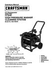
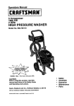
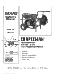
KNOW YOUR HIGH CLEANING
SYSTEM
Read this owner's manual and safety rules before operating your cleaning system. Compare the
illustrationswith your cleaning system to familiarize yourselfwith the locationsof various controlsand
adjustments.
System Rinse, Detergent and
Chemical Reservoirs with
Internal Filter and Baffle
Spray Gun
GasTank
Dual Lance with QuickConnect Fitting
Air Filter
F
High PressursHose
PrimerBulb
Water Inlet
Oil Pill Cap
Dial-A-Cleaner'*
Selector Knob
Pump
Pressure
CommandTM
Air Filter - Dry type filter element limitsthe amount of
dirt and dust that gets in the engine.
OII Fill Cap - Fill engine with oil here. See page 8 for
oil recommendations.
DiaI-A-Clsaner TM Selector Knob - Selects any one
of three chemicals or the clean water system rinse.
Pressure Command TM - Sets output water pressure.
Dual Lance with Quick-Connect Fitting- The dual
lance attaches to the spray gun and allowsyou to
switch from low pressure mode, for applying
chemicals, to high pressure mode, for cleaning.The
quick connectfitting lets you quickly exchangethe four
provided nozzles to adjust the spray pattern of the
high pressure spray.
Pump - Develops high water pressure.
Primer Bulb - Used to start a cold engine.
Spray Gun - Controlsthe applicationof water onto
cleaningsurface with triggerdevice. Includessafety
latch.
System Rinse, Detergent and Chemical Reservoirs
with Internal Filter and Baffle - Used to provide
detergent or other chemicalsto the low pressure water
stream.
Water inlet - Connectionfor garden hose.
Gas Tank - Fill gas tank with regular unleaded
gasoline hera.
High Pressure Hose - Connect one end to the spray
gun.
5
HOW TO USE YOUR CLEANING SYSTEM
Pull back the collar on the quick connect and pull
the current nozzle off; Store the nozzle in the space
provided on the controlpanel.
Read these instructionsand learn how to use your
cleaning system before you attempt to startyour
cleaning system. If you have any problems operating
your cleaning system, please call the pressurewasher
helpUneat 1-800-222-3136.
How To Use the NozTJes
,_
DANGER:
nozzleswithout
lockingthe Never
safety exchange
latch on the
trigger.
The quick-connect on the dual lance allows you
switch between four different nozzles. The nozzles
vary the spray pattern of the high pressurestream as
shown below.
White
Note: For a more gentle rinse, select the 40* or 25"
degree nozzle. To scourthe surface, select the 15° or
0 ° nozzle.
•
Green
Pull backthe collar, insert the new nozzle and
release the collar, making sure it becomes flush
with the end of the quick connect. Pull on the
nozzle to make sure it is securely in place.
Note: The chemicalnozzle is permanently affixed to
your dual lance and has a spray pettem of 25
degrees. It must be used when applying chemical.
Yellow
Red
too
•
For most effective cleaning, keep spray nozzle
between 8 to 24 inchesaway from cleaning
surface.
•
Damage to the surface may occur if you get the
spray nozzle too clove to it.
Cleaning With The Nozzles ana ,_lying
Chemical
A
In order t0 Change the nozzle being used, followthese
instructions:
WARNING: You must attach all hoses before
you startthe engine. Starting the engine without
all the hoses connected and without the water
turned ON will damage the pump.
IMPORTANT: Use soaps designed specificallyfor
pressure washer cleaning systems. Household
detergents could damage the pump.
Engage the safety latch on the spray gun.
Up to three (3) different solutions can be carded on the
cleaning system at one time. To apply detergent follow
these steps:
•
Safety Latch
Dilution is necessary when using the supplied
chemical packets, Simply snip one comer of the
plastic pouch, pour the chemical into the tank, then
fill the tank with clean water. Label tanks with the
provided tank labels.
Pour chemical into one of
the tanks labeled A, B, C.
6
Wash and Rinse Surface
If usinganotherchemical
designed
forusewith
pressure
washers,
preparethechemical
solution
as This CraftsmanCleaning System permitsregulationof
required
bythechemical
manufacturer.
Fill
water pressureby varyingthe engine speed.
chemical
reservoir(s)
withtheprepared
solution
as output
The Pressure CommandTM found on the front panel
needed.
may be set, as follows:
RotatetheDial-A-Cleaner
TM selector knobto the
Pressure
Low
to
High
letter correspondingto the desired reservoir.
Open the chemical valve handle fully on the dual
lance by turning it countemlockwiseto place the
cleaning system in low pressure mode. Detergent
cannot be applied with the chemical valve
handle in the high pressure position.
Duty
Application
Light
Auto
Medium
Concrete
Heav"t
Paint removal
Boat
Furniture
Driveway
Deck
Degreasing
After you have applied detergent, scourthe surface
clean, as follows:
•
Close the chemicalvalve handle fullyon the dual
lance by turningit clockwiseto place the cleaning
system in high pressure mode. Chemical will not
flow when in the high pressure mode.
withSelect
the high
andpressurewater
installthe desired
stream
nozzlefollowingthe
and then rinse it
instructionson'How to Use the Nozzles" on page 6.
Adjust PressureCommancFM control to obtain
•
Connect garden hose to water inlet, check that
high pressure hose is connected to spray gun and
pump (see ASSEMBLY on page 4), and start
engine,
desired water pressure.
Expand the spray patternfor a more gentle dnsing
action. Startat top of area to be dnsed, working.
down with same actionas for cleaning.
be cleaned. Make sure there is no damage
caused by the high pressurespray.
Attachgarden
to hoseto
waterinlet
A
A
CAUTION: Before starting yourCleaning
System, make sure you have read and followed
the instructionsin the sections =Before Starting
the Cleaning System"on page 8 and "To Start
the Cleaning System" on page 8.
RINSE
Allow detergent to 'soak in' (between 3-5 minutes)
before washing and rinsing. Reapply as neededto
prevent surface from drying.
EVERY
USE
It is imperativethat the chemical selectorsystem be
rinsed after
each use
toaprevent
cloggingor
leaks: to
CAUTION:
Test
small area
of the surface
Fill the System Rinse reservoirwith clean water.
Before disconnectingthe water supply,start your'
cleaning system.
A
WARNING: Be extremely careful if you must
use the cleaning system from a ladder,
scaffoldingor any other relatively unstable
location.When you press the trigger, the recoil
from the initial spray could force you to fall, or if
you are too close to the cleaningsurface, the
high pressure spray could force you off a
climbingapparatus.
Start at lower portion of area to be washed and
work upward, using long, even overlapping strokes.
SYSTE'_MAFTER
CAUTION: Before startingyour Cleaning
System, make sure you have read and followed
the instructionsin the sections"Before Starting
the Cleaning System"on page 8 and "To Start
the Cleaning System"on page 8.
Open the chemicalvalve handle fullyon the dual
lance by tuming it counterclockwiseto place the
cleaningsystem in low pressure mode.
Rotate the Dial-A-CleanerTM selector knobto the
letter correspondingto the System Rinse tank. As
clean rinsewater is drawn throughthe system,
continuethe flow until no detergent foam is
observed.
•
Rotate the Dial-A-Cleaner TM selector Imob to the
OFF position.
BEFORE
SYSTEM
STARTING
THE
CLEANING
To add fuel to engine:
Clean area around fuel cap, remove cap.
To operatethe engineyouwillneedto do the following:
•
Add Engine Oil
Important: Never mix oil with gasoline.
• Install fuel cap and wipe up any spilled gasoline.
only use high quality detergent oil rated with API
service classificationSF or SG. Select the oil's SAE
viscositygrade accordingto your expected operating
temperature:
colder _
32°F _
warmer
,,t
II
J,
5W30
SAE 30
Although multi-viscosityoils (5W30, 10W30, etc.)
improve starting in coldweather, these multi-viscosity
oils will resultin increased oil consumption when used
above 32°F. Check your engine oil level more
frequently to avoid possibledamage from runninglow
on oil.
Add regular unleaded gasoline, slowly, to the fuel
tank.
TO START THE CLEANING
The best way to start your cleaning system engine for
the first time is to follow these instructionsstep-bystep. This starting informationalso applies whenever
you start the engine after you have let the cleaning
system sit idle for at least a day.
Place the cleaning system in an area close enough
to an outside water soume that can flow at a rate of
at least 3 gallonsper minute. Connect a garden
hose to the water spout.
•
Place cleaning system on a level surface
Clean area around oil fill cap and remove.
SYSTEM
•
•
•
Check that the high pressure hose is tigh'tly
connected to the spray gun and to the pump. See
ASSEMBLY sectionon page 4.
Check inlet screen on the water inlet. If the screen
is dirty, clean before attaching a garden hose. ff the
screen is damaged, do not connectto the garden
hose. Replace with screen provided in maintenance
kit or cell 1-800-366-PART to order a replacement
inlet screen.
Attach the the garden hose to the water inlet.
Tum on the water,
Dil Fill Cap
/
Oil Drain Plug
Pour oil from enclosed bottle intothe oil fill opening
until oil reaches the point of overflowing. Do not
overfill.
,&
CAUTION_Do
notand
runturned
pumpwithout
water
supplyconnected
on. Youthe
must
follow this cautionor the pump will be damaged.
•
•
Remove the dual lance from the spray gun.
Pull the tdgger on the spray gun and hold until a
steady stream of water appears.
•
Engage the safety latch on the spray gun.
•
Attach dual lance onto spray gun.
Install oil fillcap. Hand tighten securely.
Add Gasoline
•
Use regular unleaded gasoline with the cleaning
system engine. Fuel tank capacity is 1 gallon.
,_
DANGER:
Never
fillfuel
indoors.Never
fill
fuel tank when
engine
is tank
runningor
hot. Do not
smokewhen fillingfuel tank.
,_
CAUTION:
overfillthe fuel tank. Always
leave room Do
for not
expansion.
,&
CAUTION: Experience indicatesthat alcohol
blended fuels (calledgasohol or usingethanol
or methanol) can attract moisturewhichleads to
separation and formationof acids during
storage. Acidic gas can damage the fuel system
of an engine while in storage.
•
Move Run/Stop switch to the "Run" position.
Note: If the engine fails to start after 3 pulls, primethe
engine three (3) times and pull starter rope again.
Once the engine has started, disengage the spray
gun safety latch.
HOW TO STOP YOUR CLEANING
SYSTEM
•
•
Pressthe primerbulb three (3) times, waiting two
(2) secondsbetween each push.
Move the Run/Stop switch to the "Stop" position.
Simply shutting off the engine will not release
pressure in the system. Squeeze trigger on the
spray gun to relieve pressure in the hose.
Note: A small amount of water will squirt out when
you release the pressure.
• Rotate the Dial-A-Cleaner TM selector knob to the
OFF position to prevent chemical leakage.
SIPHONING
DO NOT siphon standing water for yourwater supply.
Contaminated, brackish or dirty water can damage the
pump. Connect only to householdwater supply.
TIPS
Never use the garden hose inlet to siphon
detergent or wax.
Grasp starter handle and pull slowly untilyou feel
some resistance.Then pull cord rapidlyto
overcomecompression,prevent kickbackand start
the engine. Let rope retum to starter slowly.
Note: The Pressure CommandTM may be placed in
any positionduring staring or operation.However, for
cold starts, it is recommendedthat the Pressure
CommandTM be placed in the Uhigh"position.
If you hold the spray nozzle too far away from the
object being cleaned, washing will not be as _'
effective.
•
•
Always store the cleaning system with the DialA-Cleaner TM selector knob to the OFF position.
CUSTOMER
RESPONSIBILITIES
MAINTENANCE TASK
HOURLY OPERATING INTERVAL
Every 25
HOUPI
Eve W 50
Hours or
yearly
0€
Y_y
SERVICE DATES
Every 100
Hours or
Yeady
Cleaning System
CheckJclean water inlet screen
on quick-connect.
xt
Ched,( high pressure ho6e.
x
Check detergent ho_e.
x
Check spray gun and assembly for leaks.
x
Purge pump of _dr and contaminants.
x
ENGINE
Check oil level.
x
x-
Service foam _r.
Service paper air Citer.
X"
Change engine oil.
X"
X
Clean/repk_cespark plug.
X
Clean spark arrestorscreen
Prepare for storage,
"
Prepare unit for storage if if is to remain
idle for longer than 30 days.
C_ean if clogged. Replace if perforated or tom.
Change oil after the first (8) operating hoursand every 50 hours thereafter. Change sooner when eperaUng under dirty or dusty
condi_ns.
._
Replace more of_n under dirty or dusty condiUons.
PRODUCT
SPECIFICATIONS
of Caiifomia a spark arrestor is required
by law (Section 4442 of the California Public
Resources Code). Other states may have similar laws.
Federal laws apply on federal lands.
In the State
Cleaning System Specifications
)RESSURE
3000 Psi
FLOW RATE
2.5 GPM
Use as directed
CHEMICAL MIX
WATER SUPPLY
TEMPERATURE
Note: If you equip the engine of your cleaningsystem
with a spark arrestor muffler,the spark arrestor must
be maintained in effectiveworkingorder by the
owner/operator.
GENERAL
Not to Exceed 140°F
The warranty of the cleaningsystem does not cover
items that have been subjectedto operator abuse or
negligence. To receive full value from the warranty,
operator must maintain cleaningsystem as instructed
in this manual.
Engine Specifications
ENGINE MODEL
RATED HORSEPOWER
SPARK PLUG: Type:
GASOLINE CAPACITY
OIL
SOLID STATE
IGNITION AIR GAP
RECOMMENDATIONS
GN-220
7.8
Some adjustmentswill need to be made periodicallyto
propedy maintain your cleaningsystem.
Champion RC12YC
or equivalent. Set
Gap to: 0.030 inch
(0.76mm)
All adjustments in the Service and Adjustments
section of this manual shouldbe made at least once
each season.
•
1 Gallon
SAE 30 weiaht
0.0125 inch
10
Once a year you shouldclean or replacethe spark
plug and replace the air filter and check the gun
and wand assembly for wear. A clean spark plug
and new air filter assure properfuel-air mixtureand
help your engine run better and last longer.
BEFOREEACH USE
Checkwaterinletscreenfordamage.
• Checkhighpressure
hoseforleaks.
Checkchemical
tanksandfillersfor damage.
•
Pull the triggeron the gun and hold.
•
When the water supply is steady and constant,
engage the safety latch and refssten the nozzle
attachment.
•
Check gun and wand assembly for leaks.
Nozzle Maintenance
•
Purge pump of air and contaminants.
•
Check engine oil level.
If the nozzle becomes restrictedor cloggedwith
foreign materials, such as dirt, excessivepump
pressure may develop. A partiallycloggednozzle can
cause a pulsingconditionduring use. This generallyis
not a pump related problem, but rathera clogged or
partiallyrsstdctednozzle.
If the nozzle becomes cloggedor partiallyrestricted,
immediately clean the nozzle with the kit includedwith
your cleaningsystem by followingthese instructions:
CLEANING SYSTEM MAINTENANCE
Check and Clean Inlet Screen
Examine garden hose inlet screen. Clean if if is
clogged or replace if it is tom.
Check High Pressure
Hose
High pressure hoses can develop leaks from wear,
kinking, or abuse, inspect hose before each use.
Check for cuts, leaks, abrasions, bulgingof cover, or
damage or movement of couplings, ff any of these
conditionsexist, replace hose immediately.
A
•
•
•
Shut off the engine and tam off the water supply.
Press triggerto relive water pressure.
Separate the dual lance from the gun.
Use the wire includedin the kit or a small paper
clip to free the foreign materials cloggingor
restrictingthe nozzle.
Insert wire Into
nozzle and tum
back and forth
to clear
obstruction.
DANGER:with
Never
a highthe
pressure
hose.
Replace
hoserepair
that meets
minimum
pressure rating of your cleaningsystem
Check Chemical Reservoirs
Tank covers shouldsnap cleanly onto tank. Ensure
chemical labels correctly identifytank contents.
Ensure that the System Rinse tank is filled with clean
water. Ensure that Dial-A-CleanerTM selector knob
rotates freely between each position.Examine the
tanks and replace if the filter is clogged
Remove additionaldebris by back flushingwater
supplythroughdual lance (Figure 2). Back flush
between 30 to 60 seconds. Back flush both lances
by tuming chemicalvalve handle.
Check Gun and Wand
Examine:h0se connectionto gun and make sure it is
secure. Test trigger by pressing if and making sure it
springsback into place when you release it. Put safety
latch in UP positionand test trigger. You should not be
able to press trigger. Replace gun immediately if it
fails any of these tests.
Purge Pump of Air and Contaminants
To remove the air from the pump, follow these steps:
•
Set up the cleaning system as described in the
ASSEMBLY section and connect the water supply.
•
•
Remove the wand extension from the gun.
•
•
Pull the trigger on the gun and hold until a steady
stream of water appears.
Reconnectthe dual lance to the spray gun.
Reconnectthe water supply,turn on the water, and
startthe engine.
•
Test the cleaningsystem by operatingwith the unit
in high and the low pressure.
To remove the contaminants from the pump, follow
these steps:
•
Set up the cleaningsystem as described in the
ASSEMBLY section, and connect the water supply.
•
Remove the nozzle attachment from the gun.
Start the engine according to instructionsin
OPERATION section.
11
O-Ring Maintenance
ENGINE MAINTENANCE
Through the normal operation of your cleaning
system, the o-rings keep the connectionsof the hoses
and gun tight and leak-free. They may become worn
or damaged with use. Provided with your cleaning
system is an o-ring Maintenance Kit containing
replacement o-rings, a rubber washer and a garden
hose inlet screen.
Maintenance, replacement or repair of the
emission control devices and systems may be
performed by any non-road engine repair
establishment or individual.
Checking Oil Level
oil level shouldbe chocked priorto each use or at
least every eight (8) hours of operation.Keep oil level
maintained.
Parts in the O-Ring Kit Include:
•
1 O-Ring, red, (p/n B2726) for the end of the
spray gun connection between gun and high/low
spray wand.
Changing Engine Oil and Oil Rlter
Change oil after first eight (8) hours of operation.
Change oil & oil filterevery fifty (50) hours thereafter.
If you are usingyour cleaning system under
extremely dirty or dusty conditions, or in extremely hot
weather, change oil more often.
Change oil whileengine is sUUwaan from nmning, ee
follows:
•
Clean area aroundoil drain plug.
Remove oil drain plug and oilfill plug and drain oil
completely intoa suitable container.
2 O-Rings, yellow, (p/n B2264) for the ends of the
high pressure hose.
Note: The above two o-rings are close in size.
Please matchcarefully to assure propero-ring
usage.
•
1 rubber washer (p/n B2385) for the inside of the
garden hose connector.
•
1 water inlet screen (p/n B2384) for the garden
hose connector.
n Rug
•
•
•
•
•
•
Toramowawomordameged
o-ring:
•
Use a small flathead screwdriverto get
underneath the o-ring and pp/it off.
12
When oil has completely drained, Install oil drain
plug and tighten securely.
Place a suitablecontainer beneath the oil filter and
tum filter countemlockwiseto remove. Discard
accordingto local regulations.
Coat gasketof new filter with engine oil. turn filter
clockwiseuntilgasket contacts tightlywith filter
adapter. Then tighten an additional3/4 turn.
Fill oil sump with recommendedoil. (See =Before
Startingthe Engine"on page 8 for oil
recommendations)
Install the oilfill plug and tightensecurely.
Wipe up any spilledoil.
ServiceAir Cleaner
Yourenginewillnotrunproperly
andmaybe
damaged
ff yourunitusinga dirtyaircleaner.
Clean
or replacetheaircleanerpaperfilleronceevery50
hoursofoperation
oroncea year,whichever
comes
To clean or replace paper air filter:
A. Clean paper filler by tapping it gentlyon a
solid surface. If the filler is too dirty, replace it
with a new one. Dispose of the old filter
properly.
Clean air cleaner cover.
first. Clean or replace more often if operating under
dusty or dirty conditions. Clean foam pre-tiller every
25 hours of operation or sooner under dusty
conditions.
To clean or replace the air cleanercomponents:
• Loosen the two screws on the air cleaner cover.
Remove the air cleaner cover.
Foam
Pra-Filter May
Stick to Cover
Insert pre-filler intothe cover, then the paper air
filler.
Reinstallthe air cleaner cover and tighten the two
(2) screws.
CleanSpark ArrestorScreen
The engine exhaust muffler has a spark arrestor
screen. Inspect and clean the screen every 100 hours
of operation or once each year, whichevercomes first.
Note: If you use yourcleaning system on any forestcovered, brush-coveredor grass-coveredunimproved
land, it must have a spark arrestor. The spark arrestor
must be maintainedin good condition by the
owner/operator.
Clsen and inspectthe spark attester as follows:
Inspect the screen and replace it if it is tom, perforated
or otherwise damaged. Do not use a defective ,
screen. If the screen is not damaged, clean it with'a
chemical solvent.
Remove the paper air filler and the foam pre-filler
from the air cleaner cover.
FO/_ll
If the spark arrestor is damaged, replace it as follows:
• Remove the four (4) screws that connect the heat
shield to the muffler.
Pre-FIIter
/
•
Remove four.-(_4)
screwsthat attach the spark
arrestor screen.
Paper
Filter
•
To clean or replace foam pre-filter:
A.
B.
Wash pre-filter in soapy water.
Squeeze pre-filterdry in clean cloth. Do not
twist. If the pre-filler is stilldirty after washing
and drying it, replace it with a new one.
Note: If you need to order a new air filter, please
call 1-800-366-PART.
C.
D.
Apply enough engine oilto saturate the
pre-filter.
•
Wrap the pre-filler in a clean dry clothand
squeeze out the excess oil. Do not twist. Set
the pre-filter aside.
•
Replace damaged screen with new screen (p/n
83083).
13
Reattach the spark arrestor screen and the heat
shield.
Clean/
O
Replace Spark Plug
Replace the spark plug yearly or every 100 hours of
operation,whichever comes first.
,_
CAUTION: Disconnectspark plug wire from
spark plug and keep wire away from spark plug.
Clean area aroundspark plug.
Remove spark plug form the cylinderhead.
•
•
Replace spark plug if the electrodesare pitted,
burnedor porcelain is cracked. For replacement
use Champion RC12YC or equivalent.
Check electrode gap with wire feeler gauge and set
gap to 0.76ram (.030 inches), if necessary.
•
•
install a correctlygapped spark plug intothe
cylinderhead, tighten secure|y.
Valve Cover
Breather Tube
Make sure the piston is at Top Dead Cer_ter('rDC)
of its compressionstroke (both valves closed). To
get the piston at top dead center, pull on the recoil
handle slowly watching the pistontrough the spark
plug hole. As you pull on the recoil handle the ,
piston should move up and down. The piston is put
Top Dead Center when it is up as high as it can go.
\
Carburetor
If you thinkyour carburetor needs adjusting,see your
nearest Sears Service Center. Engine performance
may be affected at altitudesabove 5000 feet. For
operationat higher elevations,contactyour nearest
Sears Service Center.
in-lb$
Allen Wmnol
Adjusting Valve Clearance
After the firstfilly (50) hours of operation,you should
adjust the valve clearance in the engine.
Important: If you feel uncomfortableaboutdoing this
procedure or you don't have the propertools, please
take yourcleaning system in to the nearest service
center to have the valve clearance adjusted. This is a
very importantstep to insure the longest life for your
engine.
To adjustvalve clearance:
•
•
•
Make sure the engine is at roomtemperature.
Make sure that the spark plug wire is removed from
the spark plug and out of the way.
Remove the breather tube from the valve cover.
LooNn
Jam Nut
*
Using a 10mm wrench, loosen the rockerarm jam
nut. Use an 8ram allen wrench to tum the pivotball
stud while checking clearance between the rocker
arm and the valve stern with a feeler gauge.
Correct clearance is 0.002-0.004 inch (0.050.1mm). Note: You must hold the rockerarm jam
n_ in place as you turn the pivotball stud.
,
When valve clearance is correct, hold the pivotball
stud in place with the allen wrench and tighten the
rocker arm jam nut. Tighten the jam nut to 65-85
inch-poundstorque. After tighteningthe jam nut,
recheck valve clearance to make sure ff did not
change.
Remove the four s_rews attaching the valve cover
with a #2 or 3 phillipsscrewdriver.
14
•
•
Reattach the valve cover makingsure the gasket
between the valve cover and cylinderhead is in
place. Start all four screws before tighteningor you
will not be able to get all the screws in place.
Reattach the breather tube.
•
Reattach the spark plug wire to the spark plug.
• Torque the bolts to 4.0 kg-m (22 ft-lb).
• Torque sequence is as follows: A, B, C, D, E (star
pattern).
Retorque
Head Bolts
After the first 50 hours of operation,you must retorque
the head boltsto 4.0 kg.-m. (22 ft.-Ibs.)
Important: If you feel uncomfortableabout doing this
procedure or you don't have the propertools, please
take your cleaning system in to the nearest service
center to have the valve clearance adjusted. This is a
very important step to insure the longest life for your
engine.
jE
A
Note: Only perform this adjustmentafter first50 hours
of operation. The head bolts will need no further
adjustment.
• Remove the four (4) screwsfrom the valve cover.
•
c
Remove the valve cover and gasket.
15
AFTER EACH USE
•
Flush the chemical system by selecting a tank and
run the cleaning system with nozzle in low pressure
mode. Flush until each tank is empty, then switch
the selector knob to the next tank. The last tank to
be emptied must be the System Rinse tank.
•
Connect a 3-foot section of garden hose to the inlet
adapter. Pour RV-Antifreeze (antifreeze without
alcohol) into the hose. Pull the recoil handle twice.
Water shouldnot remain in the unitfor long periods of
time. Sediments of minerals can deposit on pump
parts and "freeze" pump action. Follow these
procedures after every use:
•
Flush the chemical system by selectingthe System
Rinse tank and run the cleaning system with nozzle
in low pressure mode. Flush for one minute or until
the chemical is cleared from the system.
Shut off the engine and let it cool, then remove all
hoses.
•
,_
•
•
CAUTION:
Be sure
the engine Run/Stop
switch
is in the "Stop"
positionbeforeyou
continue.
Empty the pump of all pumped liquidsby pulling
recoil handle about 6 times with the Run/Stop
switch in the "Stop" position.This shouldremove
mostof the liquid in the pump.
Rotate the Dial-A-CleanerTM selectorknob to the
OFF position.
•
Coil the high pressure hose and inspectit for
damage. Cuts in the hose or fraying could result in
leaks and loss of pressure. Should any damage be
found, replace the hose. DO NOT attemptto repair
a damaged hose. Replace the hose with the
genuine Craftsman part.
Drain water from hose and properlyhang it on the
wire supportprovided.
• Store system in a clean, dry area.
A
DANGER: Never store the engine with fuel in
the gas tank indoorsor in enclosed,poorly
ventilatedareas where fumes may reach an
open flame, a spark, or pilot light.
WINTER STORAGE
,_
CAUTION:
You mustprotectyour
unitfrom
freezingtemperatures.
Failure to do
so will
permanentlydamage your pumpand render
your unitinoperable.
LONG TERM STORAGE
If you do not plan to use the cleaning system for more
than 30 days, you mustprepare the engine for long
term storage.
It is importantto prevent gum deposits from formingin
essentialfuel system parts such as the carb_Jretor,fuel
filter,fuel hose or tank dudng storage. Also,
experience indicates that alcohol-blended fu_ls (celled
gasohol, ethanol or methanol) can attract moisture
which leads to separation and formation of acids
during storage. Acidicgas can damage the fuel system
of an engine while in storage.
p
Protect Fuel System
,_
Remove all ga,sqlinefrom the fuel tank to prevent
gum deposits from forming on these parts and
causing possible malfunctionof engine.
Run engine unUIengine stops from lack of fuel.
Make sure you have water supply to pump inlet
connected and turned ON.
Change Oil
While engine is stillwarm, drain oil from crankcase.
Refillwith recommended grade. (See Changing Oil)
Oil Cylinder Bore
•
To protectthe unit from freez_ tempaatums:
•
DANGER:
Drainfrom
fuel open
into approved
outdoors,away
flame. Becontainer
sure
engine is cool. Do not smoke.
Remove spark plug. Squid about I ounce (30 ml) of
engine oil into the cylinder. Cover spark plug hole
with rag. Crank engine slowly to distributeoil.
_k
CAUTION:
Avoid spray from spark plug hole
when
crankingengine.
Empty all chemical reservoirsas follows:
a. Disconnecthose connectedto chemical inject
fittingon the pump. Place end of hose into
suitable container.
•
b.
•
Do not store gasolinefrom one season to another.
•
If possible, store your unit indoors and cover it to
give protectionfrom dust and dirt. BE SURE TO
EMPTY THE FUEL TANK.
Move the selector knob to Tank A and open
that tank's cover. Gravity shouldshortlyempty
the tank contents into the container.
c.
When the tank is empty, repeat step (b) for
tanks B and C.
d.
Reconnect the hose to the chemicalinject
fitting on the pump. Add 0.5 literof clean fresh
water to each tank and close tank's covers.
Install spark plug. Do not connect spark plug wire.
OTHER
IMPORTANT: NEVER cover your cleaning system
while engine and exhaust area are warm.
16
CAUSE
PROBLEM
CORRECTION
Nozzlein lowpressuremode.
Pump has followingproblems:
failure to producepressure, or
erratic pressure, chattering,loss of
1.
pressure, low water volume.
3. Inadequate water supply
2. Water inlet is blocked.
4.
5.
inlet hose is kinked or leaking
Clogged water inlet screen.
Twist chemical valve handle
t.
to place in low pressure mode.
2. Clear inlet
3. Provideadequate water flow at
least 3 gem.
4. Straighten inlethose, patch leak.
5. Replace / clean water inlet
screen.
Water supply is over 140°F.
7. Outlet hose is blocked.
8. Outlet hose leaks.
9. Gun leaks.
6. Provide cooler water supply.
7. Clear blocksin outlet hose.
8. Replace outlet hose if leaking.
9. Replace O-ring or gun if
10. Nozzle is obstructed.
necsssaq/.
10. Clear nozzle.
11. Contact Sears Service
6.
11. Pump is faulty.
Department.
1. Detergent line is collapsed or
kinked
1. Repair or replace detergent
line.
2. Chemical tank filter is clogged.
3. Nozzle is in high pressure mode.
2.
3.
Replace tank
Twist chemical valve handle
4. Dial-a-Cleaner knob is in off position.
4.
to place in low pressure mode.
Rotate knob for desired chemical.
Engine runs good when not spraying
but dies when you beginto spray.
Engine speed is too slow.
Contact Sears Service Department.
Engine _'ill net start; or starts
and runs rough
1.
2.
3.
4.
Detergent fails to mix.
Dirtyair cleaner
Out of gasoline.
Stele gasoline.
Spark plug wire not connected
to spark plug.
5. Bad spark plug.
6. Water in gasoline.
7. Ovemhoking or flooded
1. Clean or replace air cleaner.
2. Fill fuel tank.
3.
4,
Drain gas tank; fillwith fresh fuel.
Connect wire to spark plug.
5. Replace spark plug.
6. Drain gas tank; fill with fresh fuel.
7. Set engine throttlecontrol lever to
fast position,choke in mn
8.
Excessivelyrich fuel mixture.
position.
8. Contact Sears Service
9.
Intake valve stuck open or closed.
9.
10. Engine has lostcompression.
Department.
Contact Sears Service
Department.
10. Contact Sears Service
Department.
Engine shuts down during
operation
1.
2.
Out of gasoline.
Air filter dirty
Engine lacks power.
Dirtyair filter.
1.
Fill fuel tank.
2.
Replace Air filter.
Replace air filter.
17
18
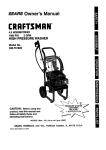
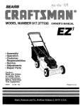
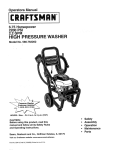
Generac
Power
Systems
GN 220, 7.8HP,
Model # EHC 04048-0
8
6
5
9
31
14
"A"
I0
12
ou_K GR_.
21
_ 523
37-_!
17
27
2O
I
24
29
22
Item B_c!__
Otv
7
8
9
78653
85272
84195
1
1
1
10
11
12
85620
00285271
84329
1
1
1
13
14
15
16
17
18
00185271
22097
82981
81675
84274
87221A
1
2
2
1
1
1
19
20
21
22
45756
72347
86962
85953
1
1
1
1
Run/Stop Switch
L.E.D. Assembly
Low Oil Shutdown
Decal
Black Sleeving
Black Wire Assembly
3-pin Male Connector
Housing
White Wire Assembly
M6 Lock Washer
M6 x 30mm Screw
Ignition Coil
Tinnerman Clamp
Low Oil Shutdown
Module
M6 x 10ram Screw
Spark Plug
Governor Lever
Wear Washer
19
23
24
A9311
83512
1
1
25
26
78604
89230
1
1
27
29
30
31
32
33
34
83503
86384
86037
36701
22152
23897
A9567
35
A9568
1
36
37
38
36919
22264
A9943
1
1
1
Adjust Screw
M8 x 15mm Taptite
Screw
60 Hz. Governor Spring
M8-1.25 x 35mm
Capscrew
M5 Lock Nut
Governor Rod
Anti-lash Spring
PHMS 10-32 x 1/2"
Lockwasher,#10
Flatwasher,#10
Bracket, Pivot/
Adjustment
Bracket, Governor
Weldment
PHMS 8--32 x 5/8"
Lockwasher#8
Clamp, Bowden
Generac Power Systems GN 220, 7.8HP, Model # EHC 04048-0
36
7
28
46
17
33
18
1
2
3
4
5
6
7
8
9
10
11
12
13
14
15
16
17
18
19
20
21
22
23
24
25
78621
76389
88411
A8897A
77168
88057
76390
83337A
78658
78659
89213J
A7637
81695
A8929
78645
A7811
72683
98752
89096
88156
A8822
78691
A57-/2
A5776
74908
1
1
1
1
5
1
2
1
1
1
1
1
2
1
1
1
1
1
1
1
1
1
1
1
1
!_
aem
_
c_v
Control Rod Assembly
Piston Pin
Piston Ring Set
Gear Cover Assembly
M8 x 52ram Head Bolt
Piston
Pin Retainer Ring
Tapered Crankshaft Assm.
Governor=R" Pin
GovernorArm Thrust Washer
Crankcase Assm.
Governor Arm
Oil Seal
Govemor Gear Assembly
Governor Gear .C-Ring
Govemor Spool
1/8" NPT Pipe Plug
Camshaft Assembly
Crankcase Gasket
Valve Stem Seal
Cylinder Head Gasket
Oil Pressure Relief Cover
Oil Pressure Spring
11/32" Ball
M5 Form Screw
26
27
78606
76361
4
1
28
29
30
31
32
33
34
36
37
38
39
40
41
42
43
44
45
46
47
48
49
50
89230
99922
A1720
88401
84186
83192
86254
21705B
90082
90081
88396A
83235
80336
96362
77161
77160
76307
88403
72657
88412
76329
21944E
6
1
2
2
2
1
1
1
1
1
2
2
1
1
2
2
2
1
2
1
1
2O
Lo_a
M6-1 .Ox 12mm Screw
Govemor Gear Thrust
Washer
M8-1.25 x 35mm Screw
Spring Washer
Valve Spring Retainer
Valve Spring
Valve SpringWear Washer
Geroter Set
=O" Ring
Cylinder Head Assembly
Exhaust Valve
Intake Valve
Push Rod
Tappet
Oil Pick-upAssembly
Rocker Cover Gasket
Pivot Ball Stud
GN-190/220 Rocker Arm
Rocker Arm Jam Nut
Push Rod Guide Plate
1/4" NPT Pipe Plug
Rocker Cover Assembly
Plastic Oil Fill Plug
Complete Long Block
Generac Power Systems GN 220, 7.8HP, Model # EHC 04048-0
47
/
40
Item
_
ow
31
32
33
34
35
36
37
38
39
90947
90051
57058
80318
80316
20136
22097
49813
21202
1
1
1
1
2
1
2
2
1
40
41
42
36935
80303
21201
2
1
1
43
44
45
46
47
48
21203
21200
66476
59635
78601
78602
1
1
1
1
1
1
41
DescriDtior!
Breather Hose
Manifold Head Gasket
M6 x 55mm Capscrew
M6 x 25ram Capscrew
M6 x 30mm Screw
Intake Manifold
M6 Lock Washer
M6 Hex Nut
Carburetor/Air Box
Gasket
#10-32 x 3/4" Screw
Canal Cover
Carburetor/Manifold
Gasket
Carburetor
Air Cleaner Base
M6 x 12mm Capscrew
#8 x 3/8" PlasUta Screw
Air Filter
Precleaner
21
48
/
Generac
Power
Systems
GN 220, 7.8HP,
Model
# EHC 04048-0
1
I
79
j
2--1
9O
3
80
/
81
4
.era P_a[t__ otv
1
2
3
4
5
6
94820
91848
84982
92978
99236
70185
1
1
1
2
1
1
lt.ean Pa_#
_]atLoJz
Expansion Plug
Oil Filter Gasket
Oil Filter Adapter
M6 x 20mm Screw
Oil Pressure Switch
Oil Filter
78
79
80
81
90
82774
SRV77182E
83312
81810
A2.842
82
83
84
85
86
87
88
89
90
91
92984
45756
78609
78608A
90695A
89739
66476
A,?.799
A2842
78651C
QtX
1
1
1
1
1
Description
Woodruff Key
Rywheel (220cc)
Conical Washer
M16 Hex Nut
Recoil Cup
91
84
\
86
88
83
22
Qtv
1
4
2
1
1
1
9
1
1
1
DeseriDtion
Top Wrapper
M6 x 10ram Screw
Cover Bolt
Air Box Cover
Blower Housing
Lower Wrapper
M6 x 12mm Capscrew
Recoil Assembly
Recoil Cup
Backplate
Generac
Power Systems
GN 220, 7.8HP,
Model # EHC 04048-0
59
Rein Pa_#
55
57
58
59
60
61
83512
95213
77395
95214
30340
48031C
2
1
2
1
12"
1
23
M6 x 15 Taptite
Tank Bracket
M6 Flange Nut
Tank Cradle
1/4" ID Hose
Hose Clamp
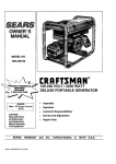
Craftsman 3000 PSi Cleaning System 580.768050
Pump
31
30
1_6
I
4
9
10
3
25
14
16
18
19
2O
37
4°
9
36
24
Craftsman 3000 PSI Cleaning System 580.768050
Pump
Rein P_a[L
_ern
1
2
3
B2218
B2260
94738
1
1
1
4
5
6
7
93887
96400
99735
93652
1
3
1
1
8
93876
1
9
Order B2480
3
16
11
12
13
Order B2480
Order B4123
Order 134123
97027
3
3
3
3
14
15
16
17
18
19
20
96137
95138
B2665
93874
B3769
46580
95320
1
1
6
6
1
3
1
21
93644
1
22
B2668
1
O-RING, 1.625 x .103
ADAPTOR, Engine
WASHER, Beelleville 16
x 2.7
NUT, Jam M16 x 1.5
SPRING, Piston Return
ASSY., Oil Breather/FUl
SPRING, Thermal ByPass
O-RING, 2.9 x 6.5 x
1.78
SEAL, High PrsssuTe
PTFE
RING, Bearing Seal
RING, Hytdle Back-Up
O-RING, 2.6 x 26.6 ID
TOWER, High Pressure
Port
PLUG, 1/6 x 28 NPT
HEAD, (Brass with Tap)
WASHER, Steel Special
SHCS, M8 x 1.25 x 75
ASSY., Unloader
SHCS, M6 x 1 x 45
CONNECTOR, Garden
Hose
ACTUATOR, Thermal
By-Pass
GASKET, Head
23
95416
1
24
25
40945
93790
6
1
26
95165
1
27
28
29
30
B22.61B
B2217
SRV97672V
......
4
4
0
1
31
......
1
32
33
34
......
B2480
......
1
0
3
35
36
......
......
1
3
37
38
39
40
41
42
43
44
......
B3508
......
......
B4123 ._
......
B4124
......
3
0
3
1
0
6
0
1
25
PISTON, Thermal ByPass
SHCS, M6 x 1 x 20
O-RING, 114 x 119 x
2.6
ADAPTOR, Tapered
Engine Shaft
SCREW, 5/16 x 3/4
O-RING, .239 x .070
KIT, AXIAL CAM
ASSY., Beadng Roller
Thrust 15.5
CAM, Axial 2.5G/5.5
Race
BEARING, Roller Thrust
KIT, PISTON REPAIR
ASSY., Ceramic Piston
& Cap
SHOE, Piston Pivot
SEAL, Oil Piston 15
TC4
SEAL, Piston"U" Cup
KIT, CRANKCASE
SPACER, Pilot
ASSY., CRANKCASE
KIT, CHECK VALVE
ASSY., Check Valve
KIT, SPACER PLATE
ASSY+,Spacer Plate
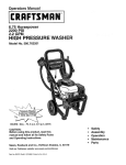
Craftsman
Main Unit
3000
PSI Cleaning
System
580.768050
26
Craftsman
Main Unit
3000 PSI Cleaning System 580.768050
_
_
1I._31._!!!_!
ow
2
3
4
5
6
7
8
9
10
B3608A
30809
B3576
B3599
B3695
B3222A
B3222B
B3222C
B3222D
1
4
1
4
8
1
1
1
1
11
12
13
14
15
16
17
B3376B
96307
86292
B3311
B3721
B3377
EB3115
1
1
4
1
1
3
1
18
19
20
21
22
23
24
25
26
27
28
29
91526
49226
51716
B3306
B3840A
B3840B
B3840C
B3840D
B3601C
48031G
EB3620
B2071
2
2
2
1
1
1
1
1
1
4
1
2
51
52
53
54
55
56
57
58
59
60
61
62
63
64
65
66
67
68
69
70
71
72
73
74
42909
40976
89476
83071
83208
39414
66476
B1436A
134341
B3589
B3454
B3604
B1748
ES3618
B3591
B3636
132508
AB3061
B2730
B3735
B4270
96207A
70453
67989
2
2
1
1
1
1
2
1
1
1
1
1
1
1
1
1
1
1
1
1
1
1
1
6
75
76
77
21216
21217
NSP
1
_.1
1
30
31
32
B't779
B2347
31669
2
2
1
33
34
35
36
37
38
39
40
41
42
43
44
45
46
47
48
49
46476
B2759
B1460
30340C
96193
48031C
95549
94994
96002
96001
21545
B1288
B4140
88521
75402
52858
27007
2
1
1
1
1
5
1
1
4
4
1
1
1
2
2
2
2
78
79
80
81
82
83
900
52857
A1701
B3706
38750
97098
21424
NSP
2
1
1
2
1
1
1
50
50190
2
LINK, ThrottleControl
GROMMET, Rubber
DECAL, Control Panel 1210
ASSY., Chemical Tank 1 Gal.
BOLT, 1/4" - 20 with Washer
CAP, Chem Container "A"
CAP, Chem Container _B"
CAP, Chem Container "C"
CAP, Chem Container
"Water"
TAG, System Flush Water
DECAL, 1-800 Number
SELF DRILL, 10 - 16 x 3,'4"
SCRE-3N,Plastite
HANDLE, 4-Way Valve
SCREW, Plastite #8 x .75"
PANEL, Control Powder
Green
PPHMS, M5 - 0.8 x 12
LOCK WASHER, M5
NUT, Hex M5 - 0.8
ASSY., Sub 4-Way Valve
HOSE, Chemical =A"- 10"
HOSE, Chemical "B" - 12"
HOSE, Chemical "C" - 14"
HOSE, Chemical=D" - 14"
HOSE, Chemical Pump 6.0"
CLAMP, Hose 3/16"
HANDLE, Powder Green
NUT, 1/4" - 20 Flange
Locking
COVER, Hinge
END CAP, Tube
BOLT, 1/4"-20 x 1-3/4"
Carriage
CAPLUG, Tubing
HOOK, Square Neck Gun
CAP, Vinyl Black
HOSE, .25" ID
VALVE, Fuel Shut-Off
HOSE, Clamp Band 112"
CAP, Fuel
TANK, 1 Gal Fuel
BUSHING, Tank
BOLT, M6 - 1.0 x 21 Shoulder
SHIELD, Heat
TAG, Breather Cap
AXLE ROD, 1/2" x 24.65"
WHEEL
PUSHNUT, 1/2"
NUT, M8 - 1.25 Locking
MOUNT, Vibration Donut
Type
FLAT WASHER, M8
Ilern _
HHCS, M8 x 1.25 x 30
SHCS, M8 - 1.25 x 20
GASKET, Exhaust
MUFFLER
BRACKET, Muffler
HHCS, M8 - 1.25 x 35
HHCS/LW, M6 - 1.0 x 12
GUN, Molded Grip
KIT, Nozzles
KIT, 3 Pak Concentrate
KIT, Chemical Tags
MANUAL
ASSY., Dual Lance Ext.
CRADLE, Powder Ct Green
VIDEO
HOSE, 3/8" x 50'
KIT, Cleaning Nozzle
OIL BOTTLE
KIT, Maintenance
NUT,Water Inlet
DECAL, Start Instruction'
DECAL, Recoil
TAG, Warning Oil
NUT, Hex LockingFlange M8
- 1.25
MOUNT, Rubber Shock
MOUNT, Rubber Shock
ASSY., Pump (See Pump
ExplodedView)
NUT, M6 - 1.0 Locking
BRACKET, Pump Support
HOSE, Water Inlet
HHCS, M6 1.0 x 30
CAP, Garden Hose Inlet
CONNECTOR, Garden Hose
ENGINE, Generac Power
Systems GN 220,
Model # EHC 04O48
Optional Accessories Not Illustrated:
71-74400
Heavy Duty Turbo Nozzle
71-74401
25' 3/8" Replacement Extension
Hose
71-75116
O Ring Repair Kit
Garden Hose Quick Connect
71-75187
71-75197
AccessoryQuick Connect Kit
71-75199
Rotating Brush
Deck Wash
71-74301
71-74302
Vehicle Wash
71-74303
Degreaser
House Wash
71-74300
71-76430
Floor/SidingBrush
71-76431
UtilityBrush
27
CALIFORNIA AND FEDERAL EMISSION
CONTROL WARRANTY STATEMENT
As the ULGE engine owner, you should be aware that
Sears may deny any and/or all warranty coverage or
responsibilityif your ULGE engine or a
pad/componentof it has failed due to abuse, neglect,
impropermaintenance, unapproved modifications,or
the use of counterfeitand/or 'grey-market' parts not
made, supplied or approved by the odginal equipment
manufacturer.
Your Warranty Rights and Obligations
The Califomia Air Resources Board (CARB), United
States EnvironmentalProtectionAgency (EPA), and
Sears Roebuck and Co. USA (Sears) are pleased to
explain the emissionscontrol system wananty on
your 1997 and later utilityand lawn and garden
equipment engine. New Utilityand Lawn and Garden
Equipment (ULGE) engines must be designed, built,
and equipped to meet both the State of Californiaand
Federal stringentanti-smog standards. Sears must
warrant the emissioncontrolsystem on your ULGE
engine for the pedods of time listed below provided
there has been no abuse, neglect, or improper
maintenance of your ULGE engine.
You are responsiblefor presenting your ULGE engine
to a Sears authorized service center as soon as a
problemoccurs. Warranty repairs should be
completed in a reasonable amount of time, not to
exceed 30 days.
If you have any questions regardingyour warranty
dghtsand responsibilities,you should contact your
nearest authorized service center or call Sears at 1800-473-7247.
The emissionscontrolsystem may includeparts such
as the carburetor,ignitionand exhaust systems.
When a warrantable conditionoccurs, Sears will
repair your lawn and garden equipment engine at no
cost to you. Expenses covered under warranty
include diagnosis,replacement parts and labor.
Warranty Commencement
Date
The warranty peded begins on the date the ULGE
engine is delivered to the original, end-use purchaser.
Lengthof Coverage
Sears warrants to the initialowner and each
subsequentpurchaser that the engine is free from
defects in materials and workmanship which cause
the failure of a warranted part for a period of two
Manufacturer's Warranty Coverage
The 1997 and later ULGE engines are warrantedfor
two years. If any emission related componentor
system on your engine (as listed below) is found to be
defective, repairs or replacement will be performedby
an authodzed Sears service center.
Owner's
years.
What is Covered
Repair or Replacement of Parts
Warranty ResponsibiliUes
Repair or replacement of any warranted part will be
performedat no charge to the owner at an approved
Sears service center. If you have any questions
regardingyour warranty fights and responsibilities,
you shouldcontact your nearest authorized service
center or call Sears at 1-800-473-7247.
As the ULGE engine owner, you are responsiblefor
the completionof all required maintenance as listed in
your factory suppliedOwner's Manual. For warranty
purposes Sears recommendsthat you retain all
receipts coveringmaintenance on your ULGE engine.
However, Sears cannot deny warranty solelybecause
of the lack of receiptsor for your failure to ensure the
completion of all scheduled maintenance.
28
Warranty
How to Rle a Claim
Period
Any warranted part which is not scheduled for
replacement as required maintenance shall be
warranted for 2 years. Any warranted part which is
scheduled only for regular inspection and/or has
instructions to the effect of =repair or replace as
necessary _ shall also be warranted for 2 years. Any
warranted part which is scheduled for replacement as
required maintenance shall be warranted either for
the pedod of time up to its first scheduled
replacement, or for 2 years, whichever comes sooner.
If you have any questions regardingyour warranty
rightsand responsibilities,you shouldcontact your
nearest authorized service center or call Sears at 1800-473-7247.
Where to get Warranty
Service
warranty services or repairs shall be providedat all
Sears authorized service centers.
Maintenance, Replacement and Repair of
Emission Related Parts
Diagnosis
When the ULGE engine is inspected by an authorized
Sears service center, the owner shall not be held
responsiblefor diagnosticcostsif the repair is
deemed warrantable.
Any Sears approved replacement part used in the
performanceof any warranty maintenance or repair
on emission related parts willbe providedwithout
charge to the owner if the part is under warranty.
Consequential
Emission Control Warranty Parts List
Damages
Sears may be liable for damages to other engine
componentscaused by the failure of a warranted part
if the failed part was stillunder warranty.
1. Fuel Metering System:
a. Carburetorassembly
b. Fuel filter
What is not covered
2. Air InductionSystem:
a. Intake manifold
b. Air cleaner
Owner Responsibilities
Any failures caused by abuse, neglect, or improper
maintenance will not be covered.
3. CatalyticMuffler Assembly (if so equipped),
including:
Add-O_ or Modified Parts
a. Muffler gasket
b. Exhaust manifold
The use of add-on, unauthorizedor modifiedparts
constitutes sufficient reasonfor denial of submitted
warranty repairs, Sears will not be held liable for
repairsof this type.
4. IgnitionSysta_
a. Spark plug
b. Ignitionmodule
5. Crankcase Breather Tube
29
For in-home major brand repair service:
Call 24 hours a day, 7 days a week
1-800-4-MY-HOME"
Para pedir servicio de reparaci6n
(1-800-469-4663)
a domicilio-
t-800-676-5811
In Canada for all your service and parts needs call - 1-800-665-4455
Au Canada pour tout le service ou les pi6ces
For the repair or replacement
parts you need:
Call 7 am - 7 pm, 7 days a week
1-800-366-PART
(1-800-366-7278)
Para ordenar piezas con entrega a domicilio - 1-800-659-7084
For the location of a Sears Parts and Repair Center in your area:
Call 24 hours a day, 7 days a Week
1-800-488-1222
For information on purchasing a Sears Maintenance Agreement
or to inquire about an existing Agreement:
Call 9 am - 5 pm, Monday - Saturday
1-800-827-6655
SEARS
HomeCentrar
TheServiceSideof Sears"