1
Developer Note
PowerBook G3 Series 1999
Computer
4/27/99
Technical Publications
© Apple Computer, Inc. 1999
Apple Computer, Inc.
© 1999 Apple Computer, Inc.
All rights reserved.
No part of this publication may be
reproduced, stored in a retrieval
system, or transmitted, in any form
or by any means, mechanical,
electronic, photocopying, recording,
or otherwise, without prior written
permission of Apple Computer, Inc.,
except to make a backup copy of any
documentation provided on
CD-ROM.
The Apple logo is a trademark of
Apple Computer, Inc.
Use of the “keyboard” Apple logo
(Option-Shift-K) for commercial
purposes without the prior written
consent of Apple may constitute
trademark infringement and unfair
competition in violation of federal
and state laws.
No licenses, express or implied, are
granted with respect to any of the
technology described in this book.
Apple retains all intellectual
property rights associated with the
technology described in this book.
This book is intended to assist
application developers to develop
applications only for Apple-labeled
or Apple-licensed computers.
Every effort has been made to ensure
that the information in this manual is
accurate. Apple is not responsible for
typographical errors.
Apple Computer, Inc.
1 Infinite Loop
Cupertino, CA 95014
408-996-1010
Even though Apple has reviewed this
manual, APPLE MAKES NO
WARRANTY OR REPRESENTATION,
EITHER EXPRESS OR IMPLIED, WITH
RESPECT TO THIS MANUAL, ITS
QUALITY, ACCURACY,
MERCHANTABILITY, OR FITNESS
FOR A PARTICULAR PURPOSE. AS A
RESULT, THIS MANUAL IS SOLD “AS
IS,” AND YOU, THE PURCHASER, ARE
ASSUMING THE ENTIRE RISK AS TO
ITS QUALITY AND ACCURACY.
Apple, the Apple logo, and
Macintosh are trademarks of Apple
Computer, Inc., registered in the
United States and other countries.
Adobe, Acrobat, and PostScript are
trademarks of Adobe Systems
Incorporated or its subsidiaries and
may be registered in certain
jurisdictions.
Some states do not allow the exclusion or
limitation of implied warranties or
liability for incidental or consequential
damages, so the above limitation or
exclusion may not apply to you. This
warranty gives you specific legal rights,
and you may also have other rights
which vary from state to state.
Helvetica and Palatino are registered
trademarks of Linotype-Hell AG
and/or its subsidiaries.
ITC Zapf Dingbats is a registered
trademark of International Typeface
Corporation.
QuickView™ is licensed from Altura
Software, Inc.
Windows is a registered trademark
of Microsoft Corporation.
Simultaneously published in the
United States and Canada.
IN NO EVENT WILL APPLE BE LIABLE
FOR DIRECT, INDIRECT, SPECIAL,
INCIDENTAL, OR CONSEQUENTIAL
DAMAGES RESULTING FROM ANY
DEFECT OR INACCURACY IN THIS
MANUAL, even if advised of the
possibility of such damages.
THE WARRANTY AND REMEDIES
SET FORTH ABOVE ARE EXCLUSIVE
AND IN LIEU OF ALL OTHERS, ORAL
OR WRITTEN, EXPRESS OR IMPLIED.
No Apple dealer, agent, or employee is
authorized to make any modification,
extension, or addition to this warranty.
Contents
Figures and Tables
Preface
9
About This Developer Note
Contents of This Note
11
Supplemental Reference Documents
PowerPC G3 Microprocessor
12
Mac OS
12
ATA Devices
12
USB Devices
13
Open Firmware
13
Chapter 1
Introduction
11
12
15
Features
16
Peripheral Devices
18
Compatibility Issues
18
Earlier PowerBook G3 Series Computers
Expansion Bay Modules
19
RAM Expansion Modules
19
USB Ports and Devices
19
System Software
19
Machine Identification
20
Chapter 2
Architecture
18
21
Processor Module
22
G3 Microprocessor
22
Backside Cache
24
Bus Clock Speeds
24
Memory Controller and PCI Bridge
Main Logic Board
25
I/O Controller IC
25
24
3
ZiVA PC DVD Decoder
26
Ethernet PHYTER IC
26
USB Controller IC
26
Video Display Subsystem
26
Power Management Unit
27
Sound Interface IC
27
CardBus Controller IC
28
Modem Module
28
Chapter 3
Devices and Ports
29
USB Ports
30
USB Connectors
30
Transfer Types Supported
31
USB Compatibility Issues
32
Serial Port Compatibility
32
Macintosh-To-Macintosh Connections
USB Storage Devices
32
USB Controller
32
External SCSI Port
33
Hard Disk Drive
34
Hard Disk Dimensions
34
Hard Disk Connector
36
Signal Assignments
36
ATA Signal Descriptions
38
Trackpad
39
Keyboard
39
Changing the Operation of the Keyboard
Fn Key
43
Num Lock Key
43
Function-keys Checkbox
43
Function Keys
43
Embedded Keypad Keys
44
Other Alphanumeric Keys
45
Control Keys
46
Ethernet Port
46
Internal Modem
47
4
32
40
Infrared Communication Link
48
Flat Panel Display
48
External Monitors
49
Monitors and Picture Sizes
49
Monitor Connector
51
Monitor Adapter
51
External Video Connector
53
Sound System
55
Sound Inputs
55
Built-in Microphone
56
External Sound Input
56
Expansion Bay Sound Input
56
CardBus Sound Input
57
Sound Outputs
57
External Sound Output
57
Internal Speakers
57
Chapter 4
Expansion Features
59
Expansion Bay
60
Mechanical Design of Expansion Bay Modules
60
Expansion Bay Connectors
62
Signals on the Expansion Bay Connector
62
Expansion Bay Signal Definitions
63
Unused IDE Signals on the Expansion Bay Connector
Power on the Expansion Bay Connector
66
User Installation of an Expansion Bay Module
67
Sequence of Control Signals
67
Guidelines for Developers
68
RAM Expansion Slots
69
Mechanical Design of RAM SO-DIMMs
69
Electrical Design of RAM SO-DIMMs
70
SDRAM Devices
70
Configuration of RAM SO-DIMMs
71
Address Multiplexing
72
RAM SO-DIMM Electrical Limits
73
CardBus Slot
74
66
5
Chapter 5
System Software
75
The New Approach
76
What Has Changed
77
Features of the New Approach
78
Performance
78
RAM Footprint
79
User Experience
79
Data Structures and Files
79
Compatibility
79
Boot ROM Contents
80
POST Code
81
Open Firmware
81
81
Mac OS 'ndrv' Drivers
RTAS
82
Mac OS ROM Image File Contents
82
Open Firmware Script
83
Trampoline Code
83
Mac OS ROM Image
83
NewWorld Boot Process
83
What Is Different
84
Interrupt Handling
85
Outmoded Resources
85
RAM Footprint
85
RTAS
85
NV-RAM
86
NanoKernel
86
Startup Disk Control Panel
86
Open Firmware and the Device Tree
87
Open Firmware and Startup Devices
87
Interrupt Layout
88
Machine Identification
88
6
Appendix A Abbreviations
Index
91
95
7
8
Figures and Tables
Chapter 2
Chapter 3
Chapter 4
Architecture
21
Figure 2-1
Block diagram
Table 2-1
Clock speeds
Devices and Ports
23
24
29
Figure 3-1
Figure 3-2
Figure 3-3
Figure 3-4
Figure 3-5
Figure 3-6
Figure 3-7
Figure 3-8
USB Type A port
31
Maximum dimensions of the internal hard disk
35
Hard disk connector and location
36
Keyboard layout
40
Alternate operations of function and control keys
41
Embedded numeric keypad operation
42
Signal pins on the video connector
51
S-video connector
53
Table 3-1
Table 3-2
Table 3-3
Table 3-4
Table 3-5
Table 3-6
Table 3-7
Table 3-8
Table 3-9
Table 3-10
Table 3-11
Table 3-12
Table 3-13
Pin assignments on the USB port
31
Signals on the HD-30 SCSI connector.
33
Pin assignments on the ATA hard disk connector
Signals on the ATA hard disk connector
38
The function keys as control buttons
44
Embedded keypad keys
45
Control keys that change
46
Signals on the Ethernet connector
47
Flat-panel resolutions and pixel depths
49
Picture sizes supported
50
Signals on the video connector
52
Pin assignments for the S-video output connector
Picture sizes for composite video output
54
Expansion Features
Figure 4-1
Figure 4-2
Figure 4-3
37
54
59
Front view of the expansion bay module
61
Back view of the expansion bay module
61
Timing of control signals during module insertion and removal
68
9
Table 4-1
Table 4-2
Table 4-3
Table 4-4
Table 4-5
Table 4-6
Table 4-7
10
Signals on the expansion bay connector
62
Audio and control signals on the expansion bay connector
ATA signals on the expansion bay connector
64
Unused IDE signals on the expansion bay connector
66
Power lines on the expansion bay connector
66
Sizes of RAM expansion devices and modules
71
Types of DRAM devices
72
64
P R E F A C E
About This Developer Note
This developer note is a technical description of the PowerBook G3 Series 1999
computer, with the emphasis on the features that are new or different from
those of earlier PowerBook computers.
This developer note is intended to help hardware and software developers
design products that are compatible with the Macintosh products described
here. If you are not already familiar with Macintosh computers or if you would
like additional technical information, you may wish to read the supplementary
reference documents described in this preface.
Contents of This Note
0
The information in this note is arranged in five chapters and an appendix.
■
■
■
■
■
■
Chapter 1, “Introduction,” introduces the new PowerBook G3 Series
computer and describes its features.
Chapter 2, “Architecture,” describes the internal logic of the computer,
including the main ICs that appear in the block diagram.
Chapter 3, “Devices and Ports,”describes the standard I/O ports and the
built-in I/O devices.
Chapter 4, “Expansion Features,” describes the expansion features of interest
to developers. It includes development guides for expansion-bay devices, the
RAM expansion modules, and the PC Card slot.
Chapter 5, “System Software,” describes the system software that comes with
the computer, with emphasis on the new Open Firmware features.
Appendix A is a list of the abbreviations used in this developer note.
11
P R E F A C E
Supplemental Reference Documents
0
For more information about the technologies mentioned in this developer note,
you may wish to consult some of the following references.
PowerPC G3 Microprocessor
0
For more information about the PowerPC 750™ microprocessor used in the
PowerBook computer, developers may wish to refer to the standard reference,
PowerPC 740/750 Microprocessor Implementation Definition Book IV. Information
about the PowerPC 750 and other G3 microprocessors is also available on the
World Wide Web at
http://www.mot.com/SPS/PowerPC/index.html
http://www.chips.ibm.com/products/powerpc/
Mac OS
0
For a description of the version of the Mac OS that comes with the new models,
developers should refer to the Technote for Mac OS 8.6. The technote is
available on the Technote web site at
http://developer.apple.com/technotes/tn/tn1121.html
ATA Devices
0
For the latest information about the system software for ATA devices such as
the IDE drive, see Technote #1098, ATA Device Software Guide Additions and
Corrections, available on the world wide web at
http://developer.apple.com/dev/technotes/tn/tn1098.html
The web page for Technote #1098 includes a link to a downloadable copy of
ATA Device Software Guide.
The technotes are also available on the reference library issues of the developer
CD.
12
P R E F A C E
USB Devices
0
For more information about USB on Macintosh computers, developers should
refer to Apple Computer’s Mac OS USB DDK ATI Reference. Information is also
available on the World Wide Web, at:
http://developer.apple.com/dev/usb/
For full specifications of the Universal Serial Bus, developers should refer to the
USB Implementation Forum on the World Wide Web, at:
http://www.usb.org/developers/index.html
Open Firmware
0
Three Technotes provide an introduction to Open Firmware on the Macintosh
platform. They are:
TN 1061: Open Firmware, Part I, available on the Technote web site at
http://developer.apple.com/technotes/tn/tn1061.html
TN 1062: Open Firmware, Part II, available on the Technote web site at
http://developer.apple.com/technotes/tn/tn1062.html
TN 1044: Open Firmware, Part III, available on the Technote web site at
http://developer.apple.com/technotes/tn/tn1044.html
The NewWorld software architecture embodied in the new Mac OS software
follows some of the standards defined by the Open Firmware IEEE 1274-1995
specification and the CHRP binding.
The basis for the bootinfo file format and use is the document PowerPC™
Microprocessor Common Hardware Reference Platform (CHRP™) System binding to:
IEEE Std 1275-1994 Standard for Boot (Initialization, Configuration) Firmware. A
bootinfo file contains Open Firmware script, a description, information for
individual operating systems, icons, and other information. A bootinfo file can
be extended to contain non-Open Firmware information, such as “Trampoline”
code and the ToolBox ROM Image.
Other Open Firmware references of possible interest include:
IEEE 1275-1994 Standard for Boot (Initialization, Configuration) Firmware: Core
Requirements and Practices
13
P R E F A C E
IEEE Std 1275-1994 Standard for Boot (Initialization, Configuration) Firmware
(Version 1.7)
Open Firmware Recommended Practice: Device Support Extensions (Version 1.0)
Open Firmware Recommended Practice: Interrupt Mapping (Version 0.9)
14
C H A P T E R
Figure 1-0
Listing 1-0
Table 1-0
1
Introduction
1
15
C H A P T E R
1
Introduction
The PowerBook G3 Series 1999 computer carries forward the architecture of the
previous PowerBook G3 Series with a slimmer case and more powerful
features. This chapter summarizes the features of the new PowerBook G3 Series
computer and addresses issues affecting compatibility with older machines and
software.
Features
1
Here is a list of the features of the PowerBook G3 Series 1999 computer. Each
feature is described in a later chapter, as indicated in the list.
■
■
■
■
■
■
■
16
Processor: The computer has a PowerPC G3 microprocessor running at a
clock speed of 333 or 400 MHz. For more information, see “G3
Microprocessor” (page 22).
Cache: The computer has a backside L2 cache consisting of 512 KB or 1 MB
of fast static RAM. The ratio of the microprocessor and backside cache clock
speeds is 5:2. See “Backside Cache” (page 24).
Memory: The computer has two standard SO-DIMM expansion slots for
SDRAM modules. The computer comes with 64 MB of SDRAM installed.
RAM is expandable up to 384 MB total, using presently available memory
devices. See “RAM Expansion Slots” (page 69).
Hard disk storage: The computer has a built-in hard disk drive with a
capacity of 4, 6, or 10 GB. For more information and developer guidelines for
alternative hard drives, see “Hard Disk Drive” (page 34).
Display: The computer has a 14.1-inch TFT display with XGA resolution
(1024 x 768 pixels). See “Flat Panel Display” (page 48).
External monitor: All configurations support dual displays, with a standard
VGA video connector for an external video monitor with resolution up to
1280 by 1024 pixels and an S-video connector for PAL and NTSC video
monitors. See “External Monitors” (page 49).
Video RAM: The computer comes with 8 MB of video SDRAM, which
supports millions of colors on the internal display or an external monitor. See
“Video Display Subsystem” (page 26).
Features
C H A P T E R
1
Introduction
■
■
■
■
■
■
■
■
■
■
■
■
Graphics acceleration: The ATI Rage Pro graphics controller along with the
8 MB of video RAM provide 2D and 3D acceleration. For more information,
see “Video Display Subsystem” (page 26).
Battery bays: The computer has two battery bays, one on either side. The
computer can operate with the AC power adapter or with one or two
batteries installed. Each battery uses lithium ion cells and provides
4800 mAh at a nominal 10.8 V.
Expansion bay: The battery bay on the right side of the computer is also an
expansion bay for a CD-ROM drive, a DVD drive, or other IDE devices.
Storage devices in the expansion bay can be removed and replaced while the
computer is operating. For more information, see “Expansion Bay” (page 60).
CardBus slot: The computer has a CardBus slot that accepts one Type II
CardBus card or PC Card. For more information, see “CardBus Slot”
(page 74).
USB ports: The computer has two USB ports for an external keyboard, a
mouse, and other USB devices, described in “USB Ports” (page 30).
SCSI port: The computer has an external SCSI port with an HDI-30
connector. For more information, see“External SCSI Port” (page 33).
Modem: The computer has a built-in modem with 56 Kbps data rate and
V.90 support. For more information, see “Internal Modem” (page 47).
Ethernet: The computer has a built in Ethernet port with an RJ-45 connector
for 10Base-T and 100Base-TX operation. For more information, see “Ethernet
Port” (page 46).
Infrared link: The computer has an IrDA infrared link capable of
transferring data at up to 4 Mbits per second. For more information, see
“Infrared Communication Link” (page 48).
Sound: The computer has a built-in microphone and stereo speakers as well
as a line-level stereo input jack and a stereo headphone jack. See “Sound
System” (page 55)
Keyboard: The keyboard has an embedded numeric keypad and inverted-T
arrow keys. Some of the function keys are used to control the display
brightness and speaker volume. The keyboard also includes an embedded
numeric keypad; see “Keyboard” (page 39).
Trackpad: The integrated flat pad includes tap/double tap and drag
features. For more information, see “Trackpad” (page 39).
Features
17
C H A P T E R
1
Introduction
■
■
Weight: The computer weighs 2.7–2.9 kg (5.9–6.4 pounds) depending on the
configuration.
Size: The computer is 310 mm (12.2 inches) wide, 249 mm (9.8 inches) deep,
and 43 mm (1.7 inches) thick.
Peripheral Devices
1
In addition to the devices that are included with the computer, certain
peripheral devices are available separately:
■
■
The Macintosh PowerBook Intelligent Lithium Ion Battery is available
separately as an additional or replacement battery.
The Macintosh PowerBook 45W AC Adapter, which comes with the
computer, is also available separately. The adapter can recharge the internal
battery in four hours while the computer is running or in two hours while
the computer is shut down or in sleep mode.
Compatibility Issues
1
While the PowerBook G3 Series 1999 computer has many new features, there
should be no compatibility problems with applications and peripherals that
operate correctly with earlier PowerBook models, with the exceptions described
in this section.
Earlier PowerBook G3 Series Computers
1
The new PowerBook G3 Series 1999 computer is not the same as the PowerBook
G3 series or the original PowerBook G3 computer. The newest model has a
slimmer case. An article in Apple’s Tech Info Library (TIL) discusses ways to tell
these computers apart. You can read the article on the World Wide Web at:
http://til.info.apple.com/techinfo.nsf/artnum/n24604
18
Peripheral Devices
C H A P T E R
1
Introduction
Expansion Bay Modules
1
The expansion bay in the PowerBook computer is not the same as those in the
PowerBook G3 Series and PowerBook 3400 computers. Expansion bay modules
designed for earlier PowerBook computers will not fit in the PowerBook
computer. For more information, see “Mechanical Design of Expansion Bay
Modules” (page 60).
RAM Expansion Modules
1
For RAM expansion, the PowerBook G3 computer uses standard SO-DIMMs
that contain SDRAM devices. For information, see “RAM Expansion Slots”
(page 69).
IMPORTANT
The RAM DIMMs in the PowerBook computer must be
SO-DIMMs that use SDRAM devices. SO-DIMMs that use
EDO devices will not work. ▲
USB Ports and Devices
1
The USB ports take the place of the ADB and serial I/O ports found on earlier
Macintosh computers. Software shims have been added to allow existing
applications designed to work with ADB mice and keyboards to work with the
equivalent USB devices. See “USB Ports” (page 30).
The AppleVision display uses an ADB connection for computer calibration of
the display. The PowerBook G3 computer has no ADB port, and the
USB-to-ADB adapter does not work in this capacity, so the user cannot use
system software to calibrate the display. The user can still adjust the display
manually.
System Software
1
The PowerBook computer has newly designed system software that provides
Open Firmware booting and Mac OS ROM in RAM. The system software is
described in Chapter 5.
The system software that comes with the PowerBook computer is Mac OS 8.6
with the addition of the extensions and control panels required for
Compatibility Issues
19
C H A P T E R
1
Introduction
product-specific features. For a description of the general Mac OS 8.6 release,
developers should refer to the Technote for Mac OS 8.6. The technote is
available on the Technote web site at
http://devworld.apple.com/dev/technotes.shtml
Machine Identification
With the New World software, it is no longer possible to use the Box Flag to
identify the computer model. For guidelines about machine identification, see
“Machine Identification” (page 88).
20
Compatibility Issues
1
C H A P T E R
Figure 2-0
Listing 2-0
Table 2-0
2
Architecture
2
21
C H A P T E R
2
Architecture
This chapter describes the architecture of the PowerBook G3 Series 1999
computer with emphasis on the aspects that are new or different from those of
earlier PowerBook computers.
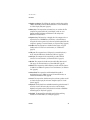
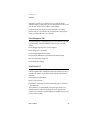
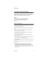
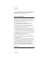
The architecture of the PowerBook G3 Series 1999 computer is designed around
two main circuit boards: the processor module and the main logic board.
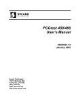
Figure 2-1 is a block diagram showing the major components and the
relationship of the processor module and the main logic board. (The modem
module shown in the diagram is described with the main logic board.)
Processor Module
2
The processor module contains the high-speed components:
■
G3 microprocessor
■
backside cache memory (512 KB or 1 MB)
■
main memory (minimum of 64 MB)
■
system ROM (1 MB)
■
memory controller and PCI bus bridge IC
This section includes a description of the microprocessor, the backside cache,
and the IC that contains the memory controller and PCI bus bridge. For a
description of the SO-DIMMs that contain the main memory, please see the
section “RAM Expansion Slots” (page 69).
G3 Microprocessor
The current family of PowerPC microprocessor designs is called “G3,” for
“generation three.” The G3 microprocessors have several features that
contribute to improved performance, including:
■
larger on-chip (L1) caches, 32 KB each for instruction cache and data cache
■
a built-in cache controller and cache tag RAM for the L2 cache
■
■
22
a separate backside bus for the L2 cache, providing faster clock speed and
overlapped bus transactions
a microprocessor core optimized for Mac OS applications
Processor Module
2
C H A P T E R
2
Architecture
Figure 2-1
Block diagram
Processor module
Modem module
Modem
controller
RAM
SO-DIMM
Datapump
Telephone
connector
RAM
SO-DIMM
512 KB
or 1 MB
backside
L2 cache
Addr
Internal
microphone
1MB ROM
PowerPC
G3
microprocessor
DAA
Data
Addr
Screamer
sound IC
Grackle
memory
controller
and PCI
bus bridge
Main logic board
PCI bus
Sound in
Sound out
Speakers
Paddington
I/O and
disk
controller
Expansion
bay connector
DP83843
PHYTER
Ethernet
IrDA link
SCSI
8MB SDRAM
Internal EIDE
hard disk
Internal display
Video monitor
S-video connector
Rage LT Pro
video
controller
and
DAC
ADB keyboard
(internal)
Cuda
power
manager
ADB trackpad
(internal)
ZIVA PC
DVD decoder
(optional)
CardBus slot
PCI1210
CardBus
bridge
Processor Module
PCI bus
2MB
SDRAM
(optional)
USB0763
USB controller
USB port 1
USB port 2
23
C H A P T E R
2
Architecture
The G3 microprocessor in the PowerBook G3 Series 1999 computer runs at a
clock speed of 333 or 400 MHz. Table 2-1 shows how the speeds of the CPU
clock, the backside cache, and the main memory bus are related.
The PowerPC G3 family of microprocessors includes the PowerPC 740™ and
the PowerPC 750™; the PowerBook G3 Series computers use the PowerPC 750.
Backside Cache
2
The controller and the tag storage for the backside cache are built into the
microprocessor chip. The cache controller includes bus management and
control hardware that allows the cache to run at an independent sub-multiple of
the processor’s clock speed, rather than at the slower clock speed of the main
system bus. In the new PowerBook G3 Series computer, the ratio of the
microprocessor and backside cache clock speeds is 5:2.
The data storage for the backside L2 cache consists of either 512 KB or 1 MB of
fast static RAM on the processor module.
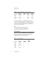
Bus Clock Speeds
2
Table 2-1 shows the clock speeds for the microprocessor, the backside cache,
and the main buses.
Table 2-1
Clock speeds
Bus or device
Clock speeds (MHz)
G3 microprocessor
333
400
Backside L2 cache
133
160
System bus
66.7
66.7
PCI bus
33.3
33.3
Memory Controller and PCI Bridge
2
The memory controller and PCI bus bridge IC is a Motorola MPC106, also
called Grackle. The Grackle IC provides the bus bridge between the processor
bus used on the processor module and the PCI bus used for the I/O controllers
24
Processor Module
C H A P T E R
2
Architecture
on the main logic board. The Grackle IC also contains the controller for the
main memory.
The main memory bus runs at a clock speed of 66.67 MHz. The internal PCI bus
runs at 33.33 MHz. To enhance performance, the Grackle IC supports
concurrent transactions on the main memory bus and the PCI bus.
Information about the Grackle IC is available on the World Wide Web at
http://www.mot.com/SPS/PowerPC/products/semiconductor/
support_chips/106.html
Main Logic Board
2
All the I/O interfaces, the video and display subsystem, the expansion bay, and
the CardBus slot are on the main logic board. The modem is on a small card
connected to the main logic board. The controller ICs on the main logic board
are connected to the PCI bus.
I/O Controller IC
2
The I/O controller IC is an ASIC called Paddington. The Paddington IC is an
integrated I/O controller and DMA engine for use in Power Macintosh
computers that have a PCI bus.
The Paddington IC contains the PCI bus arbiter. It also provides the interface
and control signals for
■
the video display subsystem
■
the built-in modem
■
the infrared link
■
the Ethernet PHYTER IC
■
the sound interface IC
■
the internal EIDE hard drive
■
a drive in the expansion bay
■
the power manager IC
Main Logic Board
25
C H A P T E R
2
Architecture
The Paddington IC is also used in the iMac computer and is similar to the
Heathrow IC used in the Power Macintosh G3 computers and Macintosh
PowerBook G3 computers. The main difference is that the Paddington IC
supports 100Base-TX Ethernet as well as 10Base-T.
ZiVA PC DVD Decoder
2
Some configurations have a built-in DVD decoder IC: a ZiVA-PC made by
C-Cube Microsystems. The IC provides video support for a DVD drive in the
expansion bay.
In addition to the video timing generation and DVD system functions, the
ZiVA-PC IC provides the following decoding functions:
■
Linear PCM audio decoding
■
MPEG-2 audio and video decoding.
■
AC-3 decoding and downmixing from 5.1 to 2 audio channels
The ZiVA-PC IC controls 2 MB of synchronous DRAM, enabling the IC to
provide full NTSC and PAL video decoding.
Ethernet PHYTER IC
2
The Ethernet interface IC is a DP83843 PHYTER made by National
Semiconductor. The PHYTER IC contains both the physical layer and the
transceiver and filter circuits. The IC provides a dual-speed Ethernet controller,
supporting both 10Base-T and 100Base-TX protocols.
USB Controller IC
2
The USB controller is a standard IC (USB0763) that supports two USB
connectors. The IC’s register set complies with the Open Host Controller
Interface (OHCI) specification.
Video Display Subsystem
2
The display subsystem consists of a graphics controller IC, 8 MB of SDRAM on
the main logic board, and ports for external video monitors.
26
Main Logic Board
C H A P T E R
2
Architecture
The graphics controller IC is an ATI Rage LT Pro. It contains 2D and 3D
acceleration engines, a digital video port, front-end and back-end scalers, a CRT
controller, and a PCI bus interface with bus master capability.
For information about the display, see “Flat Panel Display” in Chapter 3,
“Devices and Ports.” For information about external monitors and projection
devices, see “External Monitors” also in Chapter 3.
Power Management Unit
2
The power manager IC is a 68HC05 microprocessor, also called the Cuda PMU.
It operates with its own RAM and ROM. The functions of the Cuda PMU
include:
■
controlling the sleep and power on and off sequences
■
controlling power to the other ICs
■
controlling the brightness of the display
■
supporting the ADB interface to the built-in keyboard and trackpad
■
monitoring the battery charge level
■
controlling battery charging
Sound Interface IC
2
The sound interface IC, called Screamer, is a custom IC that combines a
waveform amplifier with a 16-bit digital sound encoder and decoder (codec). It
is similar to the AWAC IC used in older PowerBook models, with three main
differences:
■
It has better analog performance
■
It has a low-power mode
■
It includes a separate input used for the modem call progress sound from a
PC Card modem.
The Screamer IC is not soldered directly to the main logic board but is on a
small card mounted on the main logic board. The sound outputs from the
Screamer IC are connected to a pair of LM4861 power amplifier ICs that provide
power to drive the speakers.
Main Logic Board
27
C H A P T E R
2
Architecture
CardBus Controller IC
2
The CardBus controller IC is a PCI1210 device made by Texas Instruments. It
supports both 16-bit PC Cards and 32-bit CardBus Cards.
Modem Module
2
The built-in modem is on a separate hardware module that is connected to SCC
port A of the Paddington IC. The module contains a modem controller IC, a
datapump, and the interface to the telephone line (DAA). See “Internal
Modem” (page 47).
28
Main Logic Board
C H A P T E R
Figure 3-0
Listing 3-0
Table 3-0
3
Devices and Ports
3
29
C H A P T E R
3
Devices and Ports
This chapter describes both the built-in I/O devices and the ports for
connecting external I/O devices. Each of the following sections describes an
I/O port or device.
USB Ports
3
The PowerBook G3 Series 1999 computer has two Universal Serial Bus (USB)
ports that can be used to connect additional I/O devices such as a USB mouse,
printers, scanners, and low-speed storage devices.
For more information about USB on the Macintosh computer, refer to Apple
Computer’s Mac OS USB DDK ATI Reference. Information is also available on
the World Wide Web, at:
http://developer.apple.com/dev/usb/
For full specifications of the Universal Serial Bus, refer to the USB
Implementation Forum on the World Wide Web, at:
http://www.usb.org/developers/index.html
USB Connectors
The USB ports use USB Type A connectors, which have four pins each. Two of
the pins are used for power and two for data. Figure 3-1 is an illustration of a
Type A port and matching connector. Table 3-1 shows the pin assignments.
30
USB Ports
3
C H A P T E R
3
Devices and Ports
Figure 3-1
1
2
USB Type A port
3
Table 3-1
4
Pin assignments on the USB port
Pin
Signal name
Description
1
VCC
+5 VDC
2
D–
Data –
3
D+
Data +
4
GND
Ground
The computer provides 5-volt power at 500 mA for each of the two ports.
The USB ports support both low-speed and high-speed data transfers, at up to
1.5 Mbits per second and 12 Mbits per second, respectively. High-speed
operations requires the use of shielded cables.
Transfer Types Supported
3
The USB specification defines four data transfer types:
■
■
■
■
Control transfers, used for device configuration and initialization.
Bulk transfers, used for printers, scanners, modems, and other devices that
require accurate delivery of data with relaxed timing constraints.
Interrupt transfers, used for human interface device (HID) class devices such
as keyboards and mice, as well as devices that report status changes, such as
serial or parallel adaptors and modems.
Isochronous transfers, used for on-time delivery of data. Isochronous data
transactions are best suited for audio or video data streams.
USB Ports
31
C H A P T E R
3
Devices and Ports
Version 1.2 of the Macintosh USB system software provides functions that
support all four transfer types.
USB Compatibility Issues
3
The USB ports take the place of the ADB and serial I/O ports found on earlier
Macintosh computers, but they do not function the same way. The following
sections describe the differences.
Serial Port Compatibility
3
The latest release of the Mac OS USB DDK includes a universal Serial/USB
shim that allows processes that use the Communications Toolbox CRM to find
and use a USB modem device. The shim is called SerialShimLib and is available
as part of the Mac OS 8.6 release. For more information about the shim, and a
sample modem driver that shows how to use it, please refer to the Mac OS USB
DDK, available from the Apple Developer Development Kits page on the World
Wide Web, at
http://developer.apple.com/sdk/
Apple does not currently provide a USB Communication Class driver, so
modem vendors still need to write their own vendor-specific USB class drivers.
Macintosh-To-Macintosh Connections
3
USB is a serial communications channel, but it does not replace LocalTalk
functionality on Macintosh computers; you cannot connect two Macintosh
computers together using the USB. The best method for networking PowerBook
computers is through the built-in Ethernet port.
USB Storage Devices
3
The Macintosh USB software does not support booting from an external USB
storage device.
USB Controller
The computer uses an Open Host Controller Interface (OHCI) controller for
USB communication. Some early USB devices (most notably keyboards) can’t
32
USB Ports
3
C H A P T E R
3
Devices and Ports
interoperate with an OHCI controller. Those devices will not be supported by
the Macintosh USB system software.
External SCSI Port
3
The computer has a connector for adding external SCSI devices such as a hard
disk drive or a removable media drive. The connector is an HDI-30 high-density
30-pin connector. The signal assignments are listed in Table 3-2.
Table 3-2
Signals on the HD-30 SCSI connector.
Pin
Signal name
Pin
Signal name
1
SCSI_LINK_SEL_L(2)
16
SCSI_DB(6)
2
SCSI_DB(0)
17
GND
3
GND
18
SCSI_DB(7)
4
SCSI_DB(1)
19
DBP_L
5
TERMPWR
20
GND
6
SCSI_DB(2)
21
REQ_L
7
SCSI_DB(3)
22
GND
8
GND
23
BSY_L
9
ACK_L
24
GND
10
GND
25
ATN_L
11
SCSI_DB(4)
26
CXD_L
12
GND
27
RST_L
13
GND
28
MSG_L
14
SCSI_DB(5)
29
SEL_L
15
GND
30
IXO_L
The computer can operate in SCSI disk mode (also called target disk mode) as
long as there is a valid system image on the hard disk.
External SCSI Port
33
C H A P T E R
3
Devices and Ports
Hard Disk Drive
3
The PowerBook G3 Series 1999 computer has an internal hard disk drive with a
storage capacity of 4, 6, or 10 GB. The drive uses the extended IDE (integrated
drive electronics) interface, which is also referred to as the ATA interface. The
implementation of the ATA interface on this computer is a subset of the ATA/
IDE specification, ANSI proposal X3T10/0948D, Revision 2K (ATA-2).
The software that supports the internal hard disk is the same as that in previous
Macintosh PowerBook models with internal IDE drives and includes DMA
support. For the latest information about that software, see Technote #1098, ATA
Device Software Guide Additions and Corrections, available on the world wide web
at
http://www.devworld.apple.com/dev/technotes/tn/tn1098.html
The web page for Technote #1098 includes a link to a downloadable copy of
ATA Device Software Guide.
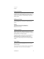
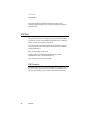
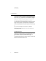
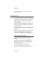
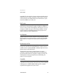
Hard Disk Dimensions
3
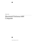
Figure 3-2 shows the maximum dimensions of the hard disk and the location of
the mounting holes. The hard disk is physically smaller than the ones in
previous PowerBook computers: only 12.7 mm (0.5 inches) high.
The minimum clearance between any conductive components on the drive and
the bottom of the mounting envelope is 0.5 mm.
34
Hard Disk Drive
C H A P T E R
3
Devices and Ports
Figure 3-2
Maximum dimensions of the internal hard disk
12.70 maximum
[0.500 maximum]
3.00
[0.118]
14.00 [0.551]
34.93 ± 0.38
[1.375 ± 0.015]
90.60
[3.567]
38.10
[1.500]
101.85 maximum
[4.01 maximum]
4.06
[0.160]
M3, 3.0 mm thread
depth minimum, 8X
61.72
[2.430]
M3, 2.5 mm thread
depth minimum, 8X
69.85
[2.75]
Note: Dimensions are in millimeters [inches].
Hard Disk Drive
35
C H A P T E R
3
Devices and Ports
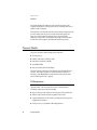
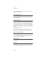
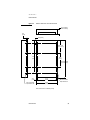
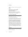
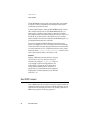
Hard Disk Connector
3
The internal hard disk has a 48-pin connector that carries both the ATA signals
and the power for the drive. The connector has the dimensions of a 50-pin
connector, but with one row of pins removed, as shown in Figure 3-3. The
remaining pins are in two groups: pins 1–44, which carry the signals and power,
and pins 46–48, which are reserved. Pin 20 has been removed, and pin 1 is
located nearest the gap, rather than at the end of the connector.
Figure 3-3
Hard disk connector and location
Key: vacant
position at pin 20
Pin 1
3.99
[0.157]
10.14 ± 0.375
[0.399 ± 0.014]
Center line of pin 44
10.24
[0.403]
12.70 maximum
[0.500 maximum]
Vacant row in
50-pin connector
14.00
[0.551]
Signal Assignments
Table 3-3 shows the signal assignments on the 44-pin portion of the hard disk
connector. A slash (/) at the beginning of a signal name indicates an active-low
signal.
36
Hard Disk Drive
3
C H A P T E R
3
Devices and Ports
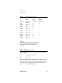
Table 3-3
Pin
number
Pin assignments on the ATA hard disk connector
Signal name
Pin
number
Signal name
1
/RESET
2
GROUND
3
DD7
4
DD8
5
DD6
6
DD9
7
DD5
8
DD10
9
DD4
10
DD11
11
DD3
12
DD12
13
DD2
14
DD13
15
DD1
16
DD14
17
DD0
18
DD15
19
GROUND
20
KEY
21
DMARQ
22
GROUND
23
/DIOW
24
GROUND
25
/DIOR
26
GROUND
27
IORDY
28
CSEL
29
/DMACK
30
GROUND
31
INTRQ
32
/IOCS16
33
DA1
34
/PDIAG
35
DA0
36
DA2
37
/CS0
38
/CS1
39
/DASP
40
GROUND
41
+5V LOGIC
42
+5V MOTOR
43
GROUND
44
Reserved
NOTE CSEL, /DASP, /IOCS16, and /PDIAG are not used; see Table 3-4
Hard Disk Drive
37
C H A P T E R
3
Devices and Ports
ATA Signal Descriptions
3
Table 3-4 describes the signals on the ATA hard disk connector.
Table 3-4
Signals on the ATA hard disk connector
Signal
name
38
Signal description
DA(0–2)
Device address; used by the computer to select one of the
registers in the ATA drive. For more information, see the
descriptions of the CS0 and CS1 signals.
DD(0–15)
Data bus; buffered from IOD(16–31) of the computer’s I/O
bus. DD(0–15) are used to transfer 16-bit data to and from the
drive buffer. DD(8–15) are used to transfer data to and from
the internal registers of the drive, with DD(0–7) driven high
when writing.
/CS0
Register select signal. It is asserted low to select the main task
file registers. The task file registers indicate the command, the
sector address, and the sector count.
/CS1
Register select signal. It is asserted low to select the additional
control and status registers on the ATA drive.
CSEL
Cable select; not available on this computer (n.c.).
/DASP
Device active or slave present; not available on this computer
(n.c.).
IORDY
I/O ready; when driven low by the drive, signals the CPU to
insert wait states into the I/O read or write cycles.
/IOCS16
I/O channel select; not used on this computer (pulled low by
1 kΩ).
/DIOR
I/O data read strobe.
/DIOW
I/O data write strobe.
/DMACK
Used by the host to initiate a DMA transfer in response to
DMARQ.
DMARQ
Asserted by the device when it is ready to transfer data to or
from the host.
Hard Disk Drive
C H A P T E R
3
Devices and Ports
Table 3-4
Signal
name
Signals on the ATA hard disk connector (continued)
Signal description
INTRQ
Interrupt request. This active high signal is used to inform the
computer that a data transfer is requested or that a command
has terminated.
/PDIAG
Asserted by device 1 to indicate to device 0 that it has
completed the power-on diagnostics; not available on this
computer (n.c.).
/RESET
Hardware reset to the drive; an active low signal.
Key
This pin is the key for the connector.
The built-in ATA devices and ATA devices in the expansion bay are separately
connected to the I/O bus through bidirectional bus buffers.
Trackpad
3
The pointing device in the PowerBook G3 Series computer is a trackpad. The
trackpad is a solid-state device that emulates a mouse by sensing the motions of
the user’s finger over its surface and translating those motions into ADB
commands.
A single button below the trackpad is used to make selections. Alternatively, the
user can tap and double tap on the pad itself. As described in the user’s
manual, the trackpad responds to one or two taps on the pad itself as one or
two clicks of the button. The user can tap and drag on the trackpad in much the
same manner as clicking and dragging with the mouse.
Keyboard
3
The keyboard is removable to allow access to the internal components and
expansion connectors inside the computer. The keyboard is held in place by two
latches located at the top of the keyboard. One latch is between the ESC key and
Trackpad
39
C H A P T E R
3
Devices and Ports
the F1 key; the other is between the F8 and F9 keys. The user can release the
latches by pulling them toward the front of the computer. There is also a
keyboard locking screw, which is accessible from the back of the computer,
above the reset button next to the RJ-11 connector. Turning the screw five or six
turns counter-clockwise unlocks the keyboard.
Like the previous PowerBook G3 Series computers, the PowerBook G3 has a
key combination for resetting the computer: Ctrl-Command-Power. There is
also a reset button on the back of the computer.
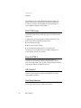
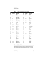
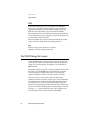
Changing the Operation of the Keyboard
3
Several of the keys on the keyboard have more than one mode of operation. The
function keys can also control the display and speakers; the keys on the right
side of the keyboard can also be used as a numeric keypad; and certain control
keys can also be used as page-control keys. These changes are controlled by the
Fn key, the Num Lock key, and the Function Keys checkbox in the Keyboard
control panel.
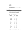
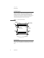
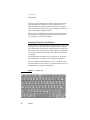
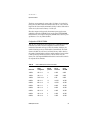
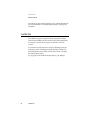
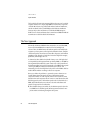
The actual appearance of the keyboard is shown in Figure 3-4. The keys that
have alternate modes of operation are shown in Figure 3-5 and Figure 3-6.
Figure 3-5 and Figure 3-6 include duplicate versions of some keys in order to
show their alternate functions. In many cases, the alternate captions shown on
the duplicate keys do not appear on the keyboard.
Figure 3-4
40
Keyboard
Keyboard layout
C H A P T E R
3
Devices and Ports
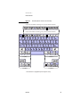
Figure 3-5
Alternate operations of function and control keys
fn key is down and checkbox is unchecked, or fn key is up and checkbox is checked.
fn key is up and checkbox is unchecked, or fn key is down and checkbox is checked.
fn key is up.
fn key is up.
fn key is down.
fn key is down.
Note: Characters on highlighted keys are enlarged for clarity.
Keyboard
41
C H A P T E R
3
Devices and Ports
Figure 3-6
Embedded numeric keypad operation
num lock is off and fn key is down.
num lock is off and fn key is up.
num lock is on.
42
Keyboard
C H A P T E R
3
Devices and Ports
Fn Key
3
Pressing the Fn key affects three sets of keys: the function keys F1–F12, the
embedded numeric keypad, and certain modifier keys.
■
■
■
It toggles the function keys between their normal control functions and their
alternate F1–F12 functions, as shown in Table 3-5 and Figure 3-5.
It selects the embedded numeric keypad on the right portion of the
alphanumeric keys, as shown in Table 3-6 and Figure 3-6.
It changes certain control keys, including the cursor control keys, to page
control keys, as shown in Table 3-7 and Figure 3-6.
Num Lock Key
3
Pressing the Num Lock key affects two sets of keys: the embedded numeric
keypad and the rest of the alphanumeric keys.
■
■
It selects the embedded numeric keypad on the right portion of the
alphanumeric keys, as shown in Table 3-6 and Figure 3-6.
It makes the rest of the alphanumeric keys functionless (NOPs), as shown in
Figure 3-6.
An LED next to the Num Lock key is lighted whenever the Num Lock function
is active.
Function-keys Checkbox
3
The Function-keys checkbox is a checkbox in the Keyboard Control Panel that
lets the user choose whether the function keys F1–F12 are primary or secondary.
Function keys primary means the function keys default to their F1–F12
functions when the the Fn key is not depressed. Function keys secondary means
the function keys default to their control-button behavior when the the Fn key
is not depressed. In either case, pressing the Fn key reverses the functions of the
function keys from the default functions set by the checkbox. The two sets of
functions of the function keys are shown in Table 3-5 and Figure 3-5.
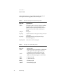
Function Keys
3
The function keys, F1–F12, are used as control buttons for the display and
sound; unused function keys are NOPs. These keys are affected by the Function
Keyboard
43
C H A P T E R
3
Devices and Ports
keys checkbox and the Fn key. Table 3-5 is a list of the function keys and their
operation as control buttons.
Table 3-5
The function keys as control buttons
Key name
Control button
F1
Decrease display brightness
F2
Increase display brightness
F3
Decrease speaker volume
F4
Increase speaker volume
F5
Num Lock
F6
Mute speaker
F7
NOP
F8
NOP
F9
NOP
F10
NOP
F11
NOP
F12
NOP
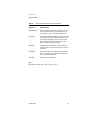
Embedded Keypad Keys
A subset of the alphanumeric keys are also used as an embedded keypad.
Figure 3-6 shows the keys making up the embedded keypad. These keys are
44
Keyboard
3
C H A P T E R
3
Devices and Ports
affected by the Fn key and the Num Lock key. Table 3-6 is a list of the keys
making up the embedded keypad.
Table 3-6
Embedded keypad keys
Key
name
Keypad
function
6
Clear
7
7
8
8
9
9
0
/
-
=
U
4
I
5
O
6
P
*
J
1
K
2
L
3
;
–
M
0
,
NOP
.
.
/
+
Other Alphanumeric Keys
3
When the embedded numeric keypad is active, the other alphanumeric keys
can be made to have no operation (NOP). The affected keys include certain
special character keys: equal sign, right and left brackets, backslash, and
straight apostrophe. These keys are affected by the Num Lock key.
Keyboard
45
C H A P T E R
3
Devices and Ports
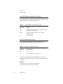
Control Keys
3
The cursor control keys are also used as page control keys. Another set of keys
take on the functions of keys on a PC keyboard, for use with PC emulation
software. These keys are affected by the Fn key. Table 3-7 is a list of the affected
keys and their alternate functions.
Table 3-7
Control keys that change
Key name
Alternate function
Shift
Right shift key
Control
Right control key
Option
Alt gr (right Alt key)
Command
Windows® key
Enter
Menu key (for contextual menus)
Left arrow
Home
Up arrow
Page up
Down arrow
Page down
Right arrow
End
Ethernet Port
3
The computer has a built-in 10/100 Mbps Ethernet port. The user can connect it
to either a 10Base-T or a 100Base-TX hub; the port will automatically sense
which type of hub is connected.
46
Ethernet Port
C H A P T E R
3
Devices and Ports
The connector for the Ethernet port is a a short, shielded RJ-45 connector on the
back of the computer. Table 3-8 shows the signals and pins on the connector.
Table 3-8
Signals on the Ethernet connector
Pin
Signal
name
Signal definition
1
TXP
Transmit (positive lead)
2
TXN
Transmit (negative lead)
3
RXP
Receive (positive lead)
4
–
Not used
5
–
Not used
6
RXN
Receive (negative lead)
7
–
Not used
8
–
Not used
The Ethernet interface in this computer conforms to the ISO/IEC 802.3
specification, where applicable.
Internal Modem
3
The PowerBook G3 Series computer comes with a built-in modem. The
connector for the modem is an RJ-11 connector on the back of the computer.
The modem has the following features:
■
■
modem bit rates up to 56 Kbps (supports K56flex and V.90 modem
standards)
fax modem bit rates up to 14.4 Kbps
The modem appears to the system as a serial port that responds to the typical
AT commands. The modem provides a sound output for monitoring the
progress of the modem connection.
Internal Modem
47
C H A P T E R
3
Devices and Ports
Infrared Communication Link
3
The computer has a directed infrared (IR) communication link connected
internally to serial port B. When the computer is placed within range of another
device with an IR interface, it can send and receive serial data using one of
several communications protocols. The other device may be another
IR-equipped PowerBook, a desktop computer with an IR communications link,
or some other device that complies with the Infrared Data Association (IrDA)
standard. The minimum range of the IR link is approximately 2 inches, and the
maximum range is 34 inches for IrDA compliant devices and 6 feet for
PowerBooks.
The IR link in the Macintosh PowerBook G3 Series computers supports IrDA at
up to 4.0 Mbps. The IrDA modulation method complies with the IrDA physical
layer standard, which can be found at ftp://irda.org.
Flat Panel Display
3
The PowerBook G3 Series 1999 computer has a built-in color flat panel display
that is 14.1 inches across, measured diagonally. The display contains 1024 by
768 pixels and can show up to millions of colors. The display is backlit by a cold
cathode fluorescent lamp (CCFL). The display uses TFT (thin-film transistor)
technology for high contrast and fast response.
The graphics controller IC includes a scaling function that expands smaller
images to fill the screen. By means of the scaling function, the computer can
show images at either 640 by 480 or 800 by 600 resolution using the full screen.
Scaling up of smaller displays also reduces the pixel resolution of the display, as
shown in Table 3-9.
The scaling function is available only when the internal flat panel is the only
active display. When the internal display and an external monitor are both
operating and mirror mode is selected, both displays show full-sized images
only when the display resolution for the external monitor is set to the standard
resolution: 1024 by 768. Both displays can operate with other resolution
settings, but in mirror mode, one of them will have a display that is smaller
than the full screen and has a black border around it. With the resolution for the
48
Infrared Communication Link
C H A P T E R
3
Devices and Ports
external monitor set to 640 by 480 or 800 by 600, the image on the internal
display is smaller than the screen. For resolution settings larger than 1024 by
768, the image on the external monitor is smaller than the screen.
When the flat panel display and an external video monitor are operating at the
same time, half the video memory is available for each, so the maximum pixel
depth at the largest image sizes is less. These modes and restrictions are
summarized in Table 3-9.
Table 3-9
Flat-panel resolutions and pixel depths
Image size
Pixel
resolution
Pixel depth,
no external
monitor
Pixel depth,
with external
monitor
640 by 480
58 dpi
24 bpp
24 bpp
800 by 600
71 dpi
24 bpp
24 bpp
1024 by 768
91 dpi
24 bpp
16 bpp
External Monitors
3
The computer has a built-in connector for an external VGA, SVGA, or XGA
monitor or projection device. An adapter, included with the computer, allows
the user to attach a standard Apple video cable. The computer also has an
S-video connector that supplies a video signal for an NTSC or PAL video
monitor or VCR.
An external monitor or projection device connected to the computer can
increase the amount of visible desktop space. This way of using an external
monitor is called dual display to distinguish it from mirror mode, which shows
the same information on both the external display and the built-in display.
Monitors and Picture Sizes
3
With the included adapter, the PowerBook G3 Series 1999 computer can be used
with any Apple monitor, including the AV monitors, the 17-inch and 20-inch
External Monitors
49
C H A P T E R
3
Devices and Ports
multiple scan monitors, and the latest Apple Studio Displays. The computer
also supports VGA, SVGA, and XGA monitors. Table 3-10 lists the picture sizes
and frame rates supported.
Table 3-10
50
Picture sizes supported
Picture size (pixels)
Frame rate
Pixel depth,
flat panel
inactive
512 by 384
60 Hz
24 bpp
24 bpp
640 by 480
60 Hz
24 bpp
24 bpp
640 by 480
67 Hz
24 bpp
24 bpp
640 by 480
72 Hz
24 bpp
24 bpp
640 by 480
75 Hz
24 bpp
24 bpp
640 by 480
85 Hz
24 bpp
24 bpp
640 by 870
75 Hz
24 bpp
24 bpp
800 by 600
56 Hz
24 bpp
24 bpp
800 by 600
60 Hz
24 bpp
24 bpp
800 by 600
72 Hz
24 bpp
24 bpp
800 by 600
75 Hz
24 bpp
24 bpp
800 by 600
85 Hz
24 bpp
24 bpp
832 by 624
75 Hz
24 bpp
24 bpp
1024 by 768
60 Hz
24 bpp
24 bpp
1024 by 768
70 Hz
24 bpp
24 bpp
1024 by 768
72 Hz
24 bpp
24 bpp
1024 by 768
75 Hz
24 bpp
24 bpp
1024 by 768
85 Hz
24 bpp
24 bpp
1152 by 870
75 Hz
24 bpp
24 bpp
External Monitors
Pixel depth,
flat panel
active
C H A P T E R
3
Devices and Ports
Table 3-10
Picture sizes supported (continued)
Picture size (pixels)
Frame rate
Pixel depth,
flat panel
inactive
Pixel depth,
flat panel
active
1280 by 960
75 Hz
24 bpp
16 bpp
1280 by 1024
60 Hz
24 bpp
16 bpp
1280 by 1024
75 Hz
24 bpp
16 bpp
The computer includes 8 MB of video memory, which is enough to provide
pixel depths up to 24 bits per pixel on all supported monitors. When an external
video monitor and the flat panel display are operating at the same time, half the
video memory is available for each. In that case, the maximum pixel depth
available on the external monitor at the 1280-by-960 and 1280-by-1024 picture
sizes is only 16 bpp.
Monitor Connector
3
The connector is a standard DB9/15 connector for use with a VGA, SVGA, or
XGA monitor. Figure 3-7 shows the pin configurations and Table 3-11 lists the
signal pin assignments.
Figure 3-7
1
2
6
11
Signal pins on the video connector
3
7
12
4
8
13
5
9
14
10
15
Monitor Adapter
3
The computer comes with a monitor adapter that allows the user to connect a
standard Apple monitor cable to the computer. The Apple part number for the
adapter is 590-1118.
To identify the type of monitor connected, the computer first determines
whether the adapter is connected. It does this by checking pin 11; on the
External Monitors
51
C H A P T E R
3
Devices and Ports
Table 3-11
Signals on the video connector
Pin
Signal name
Description
1
RED
Red video signal
2
GREEN
Green video signal
3
BLUE
Blue video signal
4
MONID(0)
Monitor ID signal 0
5
GND
DDC return
6, 7, 8
AGND_VID
Analog video ground
9
+5V_IO
5 V power for I/O device
10
GND
HSYNC and VSYNC ground
11
VGA_ID
VGA ID signal
12
MONID(2)
Monitor ID signal 2
13
HSYNC
Horizontal synchronization signal
14
VSYNC
Vertical synchronization signal
15
MONID(1)
Monitor ID signal 1
adapter, this pin is connected to the VSYNC signal. If the adapter is not found,
the computer next checks to determine whether a DDC-type monitor is
connected. DDC is the interface that provides monitor ID signals for VGA and
SVGA monitors.
If the computer does not detect a DDC-capable monitor, it uses the Apple
monitor sense codes on the signals MONID(0–2) in Table 3-11. For a description
of the sense code system, developers should refer to Technote HW 30 - Sense
Lines. To find out how to obtain Apple Computer’s Technotes, see
“Supplemental Reference Documents” (page 12).
52
External Monitors
C H A P T E R
3
Devices and Ports
Note
The first time the user starts up with an SVGA or XGA
monitor, the video card treats it as a VGA monitor and
shows a 640-by-480 pixel display. The user can switch to a
larger display mode from the Monitors & Sound control
panel; when that happens, the computer changes the
display to the larger mode immediately and uses that mode
the next time it is started up. ◆
External Video Connector
3
The 1999 PowerBook G3 Series computer has an S-video connector for
composite video output to a PAL or NTSC video monitor or VCR. The video
output connector is a 7-pin S-video connector. Figure 3-8 shows the
arrangement of the pins and Table 3-12 shows the pin assignments on the
S-video connector.
Figure 3-8
4
2
S-video connector
3
1
External Video Connector
53
C H A P T E R
3
Devices and Ports
Table 3-12
Pin assignments for the S-video output connector
Pin
number
S-video output connector
1
Analog GND
2
Analog GND
3
Video Y (luminance)
4
Video C (chroma)
5
Composite video
6
Unused
7
Unused
An adapter is available that can be plugged into the S-video connector and
accepts an RCA plug from a composite video monitor.
The 1999 PowerBook G3 Series computer provides composite video output at
picture sizes and frame rates compatible with the NTSC and PAL standards; the
picture sizes are listed in Table 3-13. Those picture resolutions produce
underscanned displays on standard monitors.
Table 3-13
54
Picture sizes for composite video output
Picture size
Pixel depth
512 by 384
24 bpp
640 by 480
24 bpp
720 by 480
(NTSC only)
24 bpp
720 by 576
(PAL only)
24 bpp
External Video Connector
C H A P T E R
3
Devices and Ports
Table 3-13
Picture sizes for composite video output
Picture size
Pixel depth
800 by 600
24 bpp
832 by 624
24 bpp
1024 by 768
24 bpp
Sound System
3
The 16-bit stereo audio circuitry provides high-quality sound input and output
through the built-in microphone and speakers. The user can also connect
external input and output devices by way of the sound input and output jacks.
The sound system is based on the Screamer codec IC along with input and
output amplifiers and signal conditioners. The Screamer codec supports three
channels of digital sound: two stereo channels plus a multiplexed channel. The
sound system supports sample sizes up to 16 bits and sample rates of
11.025 kHz, 22.05 kHz, and 44.1 kHz.
The frequency response of the sound circuits, not including the microphone and
speakers, is within plus or minus 2 dB from 20 Hz to 20 kHz. Total harmonic
distortion and noise is less than 0.05 percent with a 1-V rms sine wave input.
The signal-to-noise ratio (SNR) is 85 dB, with no audible discrete tones.
Sound Inputs
3
The sound system accepts inputs from five possible sources:
■
built-in microphone
■
external stereo sound input jack
■
1-bit sound from the CardBus socket
■
sound from the expansion bay
■
sound from the communication (modem) slot
Sound System
55
C H A P T E R
3
Devices and Ports
The microphone and the sound input jack have dedicated input channels on the
Screamer IC; the sound input from the PC Card slot has its own input, and the
other three inputs share an input on the IC. Those three inputs are switched on
and off by the hardware; they can be selected one at a time for play-through or
recording.
Built-in Microphone
3
The sound signal from the built-in microphone goes through a dedicated
preamplifier that raises its nominal 30-mV level to the 0.6-V level of the codec
circuits in the Screamer IC.
External Sound Input
3
The external sound input jack is located on the back of the computer. The sound
input jack accepts line-level stereo signals or an Apple PlainTalk microphone.
When a connector is plugged into the external sound input jack, the computer
turns off the sound input from the built-in microphone. The input jack has the
following electrical characteristics:
■
input impedance: 6.8k ohms
■
maximum level: 2.0 V rms
Note
The sound input jack accepts the maximum sound output
of an audio CD without clipping. When working with
sound sources that have significantly lower levels, you may
wish to increase the signal gain of the sound input circuit.
You can do that using the Sound Manager as described in
Inside Macintosh: Sound. ◆
Expansion Bay Sound Input
The sound input from the expansion bay has the following electrical
characteristics:
56
■
input impedance: 3.2k ohms
■
maximum level: 0.5 V rms
Sound System
3
C H A P T E R
3
Devices and Ports
CardBus Sound Input
3
The CardBus socket has a pin (SPKR_OUT) that carries a one-bit digital sound
signal output from the PC Card and input to the computer’s sound system. The
one-bit digital signal from the sound output pin is routed to the Screamer IC,
which in turn sends it to the built-in speaker and the external sound output
jack.
Sound Outputs
3
The sound system sends computer-generated sounds or sounds from an
expansion-bay device or CardBus card to the built-in speakers and the external
sound output jack.
External Sound Output
3
The sound output jack is located on the back of the computer at the left corner.
The sound output jack provides enough current to drive a pair of
low-impedance headphones. The sound output jack has the following electrical
characteristics:
■
output impedance: 33 ohms
■
minimum recommended load impedance: 65 ohms
■
maximum level: 1.17 V rms (3.3 V P-P)
■
maximum current: 18 ma rms (25 mA peak)
Internal Speakers
3
The computer has two 28mm speakers located between the keyboard and the
display. The computer turns off the sound signals to the speakers when an
external device is connected to the sound output jack and during power cycling.
Sound System
57
C H A P T E R
3
Devices and Ports
58
Sound System
C H A P T E R
Figure 4-0
Listing 4-0
Table 4-0
4
Expansion Features
4
59
C H A P T E R
4
Expansion Features
This chapter consists of three sections, each of which describes one of the
expansion features of the new PowerBook G3 Series computer:
■
“Expansion Bay”
■
“RAM Expansion Slots”
■
“CardBus Slot”
Expansion Bay
4
The battery bay on the right side of the computer also operates as an expansion
bay. The expansion bay accepts an expansion module containing either a power
device or a storage device. Storage devices available as expansion-bay modules
include Zip and Superdrive cartridge drives, a CD-ROM drive, and a
DVD-ROM drive.
Insertion of a module into the expansion bay is performed by sliding the
module into the bay, where the module is automatically latched into place. For
removal of a module, an eject lever is located in the front edge of each palmrest
of the computer. Pulling out on the eject lever releases the latch for the module
in the bay and then slides the module a little way out of the bay.
An expansion module can be inserted or removed while the computer is
operating, in sleep mode, or shut down. See “User Installation of an Expansion
Bay Module” (page 67) for details.
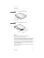
Mechanical Design of Expansion Bay Modules
Figure 4-1 and Figure 4-2 show front and back views of the expansion bay
module for a PowerBook G3 Series 1999 computer. The module is similar in
shape to an expansion module for the older PowerBook G3 Series computers,
but it is thinner and different in many important details.
60
Expansion Bay
4
C H A P T E R
4
Expansion Features
Figure 4-1
Front view of the expansion bay module
Guide rail
Latching notch
Figure 4-2
Back view of the expansion bay module
Guide rail
Locating pin
Guide rail
Connector
IMPORTANT
Expansion modules for earlier PowerBook models will not
work in a new PowerBook G3 series computer. ▲
To allow room for a 5.25-inch disk, the expansion module has a wing extending
toward the back of the computer. The expansion bay has a hinged door that
covers the extension part of the opening when a smaller device is installed.
The expansion module has a notch on the side for the latching mechanism. The
notch is on the left side of the module, which faces the front of the computer
when the module is installed.
To obtain manufacturing specifications for the expansion bay module, contact
Apple Developer Support.
Expansion Bay
61
C H A P T E R
4
Expansion Features
Expansion Bay Connectors
4
The expansion bay has two connectors: a five-contact connector for batteries
and a 60-pin connector for data devices. This section describes only the 60-pin
connector.
The connector used on the expansion modules is Foxconn part number
QL00303-A601. For information about obtaining this connector, contact Apple
Developer Support.
IMPORTANT
The expansion bay’s data connector is designed so that
when a module is inserted into the expansion bay, the first
connection is the ground by way of the connector shell,
then the power pins make contact, and last of all the signal
pins. ▲
Signals on the Expansion Bay Connector
4
Table 4-1 shows the signal assignments on the expansion bay connector. Signal
names that begin with a slash (/) are active low.
Note
The table shows the signals in the same arrangement as the
pins on the connector; that is, with pin 1 next to pin 31 and
pin 30 next to pin 60. ◆
Table 4-1
Signals on the expansion bay connector
Pin
Direction
Signal name
Pin
Direction
Signal name
1
I
MB1_SND_IN_R
31
I/O
IDE_D(12)
2
I
MB_SND_IN_COM
32
3
I
MB1_SND_IN_L
33
I/O
IDE_D(14)
4
GND
34
I/O
IDE_D(10)
5
/IOCHRDY
35
6
+5V
36
7
DIOW
37
62
Expansion Bay
GND
+5V
I/O
IDE_D(9)
GND
C H A P T E R
4
Expansion Features
Table 4-1
Pin
Direction
8
9
I/O
10
11
O
12
Signals on the expansion bay connector (continued)
Signal name
Pin
Direction
Signal name
GND
38
I/O
IDE_D(8)
IDE_D(0)
39
I/O
IDE_D(11)
IDE_INTRQ
40
IDE_ADDR(1)
41
GND
42
+5V
I/O
IDE_D(13)
GND
13
O
IDE_ADDR(0)
43
I/O
IDE_D(2)
14
O
/CS1FX
44
I/O
IDE_D(1)
+5V
45
/CS3FX
15
16
I/O
IDE_D(3)
46
GND
17
I/O
IDE_D(4)
47
IDE_ADDR(2)
GND
48
18
O
/DMACK
19
I/O
IDE_D(5)
49
GND
20
I/O
IDE_D(6)
50
/DIOR
+5V
51
DMARQ
IDE_D(7)
52
+5V
23
/IDE_RST
53
24
GND
54
GND
25
Reserved
55
Reserved
26
+5V
56
+5V
27
Reserved
57
DEVID(0)
28
GND
58
DEVID(1)
21
22
I/O
I/O
IDE_D(15)
29
I/O
MB_USB_DP
59
DEVID(2)
30
I/O
MB_USB_DM
60
/DEVIN
Expansion Bay Signal Definitions
4
The signals on the expansion bay connector are of three types: expansion bay
audio and control signals, floppy disk signals, and ATA signals. The next three
Expansion Bay
63
C H A P T E R
4
Expansion Features
tables describe the three types of signals: Table 4-2 describes the audio and
control signals and Table 4-3 (page 64) describes the ATA signals.
Table 4-2
Signal name
Signal description
/DEVIN
This signal should be low whenever a device is installed in
the expansion bay; it is used by the Paddington IC to
determine when a device has been inserted or removed.
The expansion bay module should connect this pin to
ground.
/IDE_RST
Reset signal.
CD_SND_L
Left-channel audio from a CD player in the bay (a line-level
analog signal).
CD_SND_R
Right-channel audio from a CD player in the bay (a
line-level analog signal).
CD_SND_COM
Audio common for CD sound signals.
Table 4-3
64
Audio and control signals on the expansion bay connector
ATA signals on the expansion bay connector
Signal name
Signal description
/CS1FX
Register select signal. It is asserted low to select the main
task file registers. The task file registers indicate the
command, the sector address, and the sector count.
/CS3FX
Register select signal. It is asserted low to select the
additional control and status registers on the IDE drive.
/DIOR
I/O data read strobe.
/DIOW
I/O data write strobe.
DMARQ
DMA request signal.
/DMACK
DMA acknowledge signal.
Expansion Bay
C H A P T E R
4
Expansion Features
Table 4-3
ATA signals on the expansion bay connector (continued)
Signal name
Signal description
IDE_ADDR(0–2)
IDE device address; used by the computer to select one
of the registers in the drive. For more information, see
the descriptions of the /CS1FX and /CS3FX signals.
IDE_D(0–15)
IDE data bus, buffered from IOD(16–31) of the controller
IC. IDE_D(0–15) are used to transfer 16-bit data to and
from the drive buffer. IDE_D(0–7) are used to transfer
data to and from the drive’s internal registers, with
IDE_D(8-15) driven high when writing.
IOCHRDY
I/O channel ready; when driven low by the IDE drive,
signals the CPU to insert wait states into the I/O read or
write cycles.
IDE_INTRQ
IDE interrupt request. This active high signal is used to
inform the computer that a data transfer is requested or
that a command has terminated.
/IDE_RST
Hardware reset to the IDE drive.
Note
Signal names that begin with a slash (/) are active low.
Expansion Bay
◆
65
C H A P T E R
4
Expansion Features
Unused IDE Signals on the Expansion Bay Connector
4
Several signals defined in the standard interface for the IDE drive are not used
by the expansion bay. Those signals are listed in Table 4-4 along with any action
required for the device to operate in the expansion bay.
Table 4-4
Unused IDE signals on the expansion bay connector
Signal name
Comment
CSEL
This signal must be tied to ground to configure the device as
the master in the default mode.
PDIAG
No action required; the device is never operated in
master-slave mode.
DAS
No action required.
Power on the Expansion Bay Connector
4
Table 4-5 describes the power lines on the expansion bay connector. The +5V
line is controlled by the /MB_PWR signal from the Paddington IC.
Table 4-5
Power lines on the expansion bay connector
Signal name
Signal description
GND
Ground.
+5V
5 V power; maximum total current is 1.0 A.
The power lines are equipped with current-limiting devices to protect the
computer from damaged modules or short circuits. The current limit is between
1.8 and 2.0 A.
IMPORTANT
For thermal reasons, the continuous power dissipation in
the expansion bay must not exceed a total of 5 W. ▲
66
Expansion Bay
C H A P T E R
4
Expansion Features
User Installation of an Expansion Bay Module
4
The user can insert a module into the expansion bay while the computer is
operating. This section describes the sequence of control events in the computer
and gives guidelines for designing an expansion bay module so that such
insertion does not cause damage to the module or the computer.
IMPORTANT
The user must not remove a module from the expansion
bay while the computer is communicating with the module
or, for a module with a disk drive, while the disk is
spinning. ▲
Sequence of Control Signals
4
Specific signals to the Paddington IC allow the computer to detect the insertion
of a module into the expansion bay and take appropriate action. The sequence
of events is diagrammed in Figure 4-3.
When a module is inserted, the computer performs the following sequence of
events:
1. When a module is inserted, the /DEV_IN signal goes low, causing the
Paddington IC to generate an interrupt.
2. System software responds to the interrupt and reads the DEV_ID pins to
determine the type of module inserted.
3. System software sets the /MB_PWR_EN signal low, which turns on the
power to the expansion bay.
4. System software sets the enable signal and internally notifies the appropriate
driver of the presence of a newly inserted module.
5. System software sets the /MB_RESET signal high to bring the expansion bay
module out of reset.
Essentially the reverse sequence occurs when a module is removed from the
expansion bay:
6. When the module is removed, the /DEV_IN signal goes high. The
Paddington IC responds by setting /MB_PWR high, the enable signal low,
and /MB_RESET low, and generating an interrupt. System software
responds to the interrupt and notifies the appropriate driver that the module
has been removed.
Expansion Bay
67
C H A P T E R
4
Expansion Features
When a module is resinserted into the expansion bay, the triggering event is the
same:
7. When a module is reinserted, the /DEV_IN signal goes low. The Paddington
IC responds by generating an interrupt, but keeps external signals
deactivated, because the new device may be different from the one inserted
previously.
Figure 4-3
Timing of control signals during module insertion and removal
1
2
3
4
5
6
7
/DEV_IN
MB_DEV_ID(2-0)
/MB_PWR
Power plane
Enable
Media bay
control and data
/MB_RESET
Guidelines for Developers
Each expansion bay module must be designed to prevent damage to itself and
to the computer when the user inserts or removes an expansion bay module
with the computer running.
The expansion bay connector is designed so that when the module is inserted
the ground and power pins make contact before the signal lines.
Even though you can design an expansion bay module that minimizes the
possibility of damage when it is inserted hot—that is, while the computer is
68
Expansion Bay
4
C H A P T E R
4
Expansion Features
running—your instructions to the user should include warnings about the
possibility of data corruption.
RAM Expansion Slots
4
The computer has two RAM expansion slots that accommodate standard SO
(small outline) DIMMs using SDRAM devices. One slot is on the bottom of the
system module and is normally occupied by the factory-installed SO-DIMM.
The other slot is on the top of the system module and is available for a
user-installed SO-DIMM.
RAM expansion SO-DIMMs for the PowerBook G3 Series computer must use
SDRAM devices. If the user installs an SO-DIMM that uses EDO devices, the
failure chimes will sound when the user attempts to restart the computer and
the computer will not operate.
An SO-DIMM using presently-available parts can contain either 16, 32, 64, 128,
or 256 MB of memory. Because of space limitations, a 256 MB SO-DIMM will fit
only in the top slot.
Total RAM capacity using the highest-density devices available is 384 MB and is
limited by the space available for the SO-DIMMs. The bottom slot can
accommodate a 1.5-inch SO-DIMM with up to 128 MB of SDRAM. The top slot
can accommodate a 2.0-inch SO-DIMM with up to 256 MB of SDRAM.
Mechanical Design of RAM SO-DIMMs
4
The RAM expansion modules used in the PowerBook G3 Series computer are
standard 144-pin 8-byte DRAM SO-DIMMs, as defined in the JEDEC
specifications.
The mechanical characteristics of the RAM expansion SO-DIMM are given in
the JEDEC specification for the 144-pin 8-byte DRAM SO-DIMM. The
specification number is JEDEC MO-190; it is available from the Electronics
Industry Association’s web site, at
http://www.eia.org/jedec/download/freestd/pub95/#MO
The specification defines SO-DIMMs with nominal heights of 1.0, 1.25, 1.5, or
2.0 inches. The PowerBook G3 Series computer can accommodate two
RAM Expansion Slots
69
C H A P T E R
4
Expansion Features
SO-DIMMS, one with a height up to 1.5 inches and the other with a height up to
2.0 inches.
IMPORTANT
The JEDEC specifications for the heights of the SO-DIMMs
gives a plus-or-minus 0.15 mm tolerance. In the PowerBook
G3 Series computer, the specified heights for the
SO-DIMMs are maximum heights. ▲
The JEDEC specification defines the maximum depth or thickness of an
SO-DIMM as 3.8 mm. That specification is also a maximum: Modules that
exceed the specified thickness can cause reliability problems.
Electrical Design of RAM SO-DIMMs
4
The electrical characteristics of the RAM SO-DIMM are given in section 4.5.6 of
the JEDEC Standard 21-C, release 7. The specification is available from the
Electronics Industry Association’s web site, at
http://www.eia.org/jedec/download/freestd/pub21/
The specification defines several attributes of the DIMM, including storage
capacity and configuration, connector pin assignments, and electrical loading.
The JEDEC specification for the SO-DIMM defines a Serial Presence Detect
(SPD) feature that contains the attributes of the module. SO-DIMMs for use in
the PowerBook G3 Series computers are required to have the SPD feature.
Information about the required values to be stored in the presence detect
EEPROM is in section 4.1.2.5 and Figure 4.5.6–C (144 Pin SDRAM SO–DIMM,
PD INFORMATION) of the JEDEC standard 21-C specification, release 7.
Because the SO-DIMM connector has only two clock lines, and each clock line is
limited to only 4 loads, an SO-DIMM with more than 8 SDRAM devices must
have buffers on the clock lines. The buffers must be zero-delay type, such as
phase-lock loop (PLL), which regenerates the clock signals. For example, the
computer can support a 128-MB SO-DIMM using 16 devices and a PLL clock
buffer.
SDRAM Devices
4
The SDRAM devices used in the RAM expansion modules must be self-refresh
type devices for operation from a 3.3-V power supply. The speed of the SDRAM
devices must be 100 MHz or greater.
70
RAM Expansion Slots
C H A P T E R
4
Expansion Features
The devices are programmed to operate with a CAS latency of 3. At that CAS
latency, the access time from the clock transition must be 7 ns or less. The burst
length must be at least 4 and the minimum clock delay for back-to-back random
column access cycles must be a latency of 1 clock cycle.
When the computer is in sleep mode, the maximum power-supply current
available for each bank of SDRAM is 6 mA (see the section “RAM SO-DIMM
Electrical Limits”). Developers should specify SDRAM devices with low power
specifications so as to stay within that limit.
Configuration of RAM SO-DIMMs
4
Table 4-6 shows information about the different sizes of SDRAM devices used
in the memory modules. The device configuration column shows three
numbers that characterize each type of device: the number of addresses, the
number of data bits per access, and the number of internal banks. The fourth
column in the table shows the size of each bank of devices, which is based on
the number of internal banks in each device and the number of devices needed
to make up the 8-byte width of the data bus. The last column shows the
memory size of the largest SO-DIMM with that device size that the PowerBook
G3 computer will accommodate.
Table 4-6
Sizes of RAM expansion devices and modules
Device size
Device
configuration
Devices
per bank
Size of
each bank
Size of
SO-DIMM
16 Mbits
2M x 4 x 2
16
32 MB
32 MB
16 Mbits
1M x 8 x 2
8
16 MB
32 MB
16 Mbits
512K x 16 x 2
4
8 MB
32 MB
64 Mbits
8M x 4 x 2
16
128 MB
128 MB
64 Mbits
4M x 4 x 4
16
128 MB
128 MB
64 Mbits
4M x 8 x 2
8
64 MB
128 MB
64 Mbits
2M x 8 x 4
8
64 MB
128 MB
64 Mbits
2M x 16 x 2
4
32 MB
128 MB
64 Mbits
1M x 16 x 4
4
32 MB
128 MB
64 Mbits
1M x 32 x 2
2
16 MB
128 MB
RAM Expansion Slots
71
C H A P T E R
4
Expansion Features
Table 4-6
Sizes of RAM expansion devices and modules (continued)
Device size
Device
configuration
Devices
per bank
Size of
each bank
Size of
SO-DIMM
64 Mbits
512K x 32 x 4
2
16 MB
128 MB
128 Mbits
4M x 8 x 4
8
128 MB
256 MB
128 Mbits
2M x 16 x 4
4
64 MB
256 MB
The computer accepts either one or two SO-DIMMs. The bottom slot can
accommodate a 1.5-inch SO-DIMM with up to 128 MB of SDRAM. The top slot
can accommodate a 2.0-inch SO-DIMM with up to 256 MB of SDRAM. The
memory controller configures the combined memory of the SO-DIMMs into a
contiguous array of memory addresses.
Note
The PowerBook G3 Series computer does not support
memory interleaving, so installing two SO-DIMMs of the
same size does not result in any performance gain. ◆
Address Multiplexing
4
Signals A[0] – A[13] on each RAM SO-DIMM make up a 14-bit multiplexed
address bus that can support several different types of SDRAM devices. Table
4-7 lists the types of devices that can be used in this computer by size,
configuration, and sizes of row and column addresses.
Table 4-7
72
Types of DRAM devices
Device size
Device
configuration
Size of
row address
Size of
column
address
16 Mbits
2M x 4 x 2
11
10
16 Mbits
1M x 8 x 2
11
9
16 Mbits
512K x 16 x 2
11
8
64 Mbits
8M x 4 x 2
13
10
RAM Expansion Slots
C H A P T E R
4
Expansion Features
Table 4-7
Types of DRAM devices (continued)
Device size
Device
configuration
Size of
row address
Size of
column
address
64 Mbits
4M x 4 x 4
12
10
64 Mbits
4M x 8 x 2
13
9
64 Mbits
2M x 8 x 4
12
9
64 Mbits
2M x 16 x 2
13
8
64 Mbits
1M x 16 x 4
12
8
64 Mbits
1M x 32 x 2
13
7
64 Mbits
512K x 32 x 4
12
7
128 Mbits
4M x 8 x 4
13
9
128 Mbits
2M x 16 x 4
13
8
IMPORTANT
The PowerBook G3 Series computer supports only the
types of SDRAM devices specified in Table 4-7. Other types
of DRAM devices should not be used with this
computer. ▲
RAM SO-DIMM Electrical Limits
4
Each RAM SO-DIMM must not exceed the following maximum current limits
on the +3 V supply:
Active
1.2 A (8 devices at 150 mA each)
Sleep
6 mA per bank
The maximum current specified for active operation generally rules out the use
of 4-bit-wide SDRAM devices in a RAM expansion card. Such a card would
have 16 such devices, and the 1.2 A maximum current would allow only about
75 mA per device. To stay within the current limits, RAM expansion cards
should use only 8-bit or 16-bit SDRAM devices.
RAM Expansion Slots
73
C H A P T E R
4
Expansion Features
The restriction on sleep current is required not only to maximize the battery life
but to meet the limitations of the backup battery during hot swapping of the
main battery.
CardBus Slot
The CardBus slot accepts one Type II card. The slot supports both 16-bit PC
Cards and 32-bit CardBus Cards. The card can be removed and replaced while
the computer is operating. The slot supports Zoomed Video on the card
connector.
For information about the latest version of the PC Card Manager, developers
should refer to the PC Card Manager v3.0 SDK. The SDK is available on the
March 1997 Reference Library edition of the Developer CD and on the Apple
Developer World web page at:
ftp://ftp.apple.com/devworld/Development_Kits/PC_Card_Manager/
74
CardBus Slot
4
C H A P T E R
Figure 5-0
Listing 5-0
Table 5-0
5
System Software
5
75
C H A P T E R
5
System Software
The PowerBook G3 Series 1999 computer is different from previous PowerBook
computers in that it has no single, large ROM that contains many components
of the Mac OS software, along with the 68K emulator, hardware initialization,
and the nanokernel. Instead, a small ROM provides hardware initialization
functions and provides a mechanism to load the Mac OS ROM image into
RAM. The new software architecture that is centered around ROM-in-RAM and
its ramifications is called the NewWorld architecture.
The New Approach
5
Historically, the Macintosh ROM has been structured as one monolithic ROM,
known as the Mac OS ROM, that contains both low level and high level
software. That is, the ROM contains the hardware-specific code needed by the
computer at power-up time as well as higher level Mac OS software. Examples
of hardware-specific code are drivers, feature tables, diagnostics, and hardware
initialization code. Examples of higher level software are high-level managers,
QuickDraw, SCSI Manager, and so on.
As features have been added to the Mac OS software, some of the higher level
code expanded beyond the practical limits provided by ROMs, so the ROM has
been augmented and modified by system software such as the System file and
the hardware enabler. In this way the functionality of the ROM has been spread
out among the ROM, the enabler, and disk-based system software. This
intertwining of low-level and high-level code spread out from ROM to disk has
made it difficult and time consuming to release new computers.
One way to address this problem is to separate the system software into two
logically distinct pieces. One piece holds most of the hardware-specific
components needed to boot the computer, while the other contains boot-time
Mac OS routines and components that are common to many Macintosh models.
With this approach, much of the hardware-specific code is isolated in the boot
ROM, and the Mac OS and system software code can be made abstract and
generic. This approach has several benefits.
■
76
When hardware changes are needed, only the hardware-specific code in the
boot ROM has to be modified, greatly decreasing turnaround time for new
product releases and reducing testing time and expenses.
The New Approach
C H A P T E R
5
System Software
■
■
The high-level Mac OS and system software does not need to change often.
When making a new build as a result of changing hardware-dependent code,
there is high confidence that the high-level software has not been changed.
Not changing the higher level software as often simplifies things for many
groups inside Apple, including testing, system software, software
configuration management, developer support, and publications.
Third-party developers can also benefit from this.
What Has Changed
5
Hardware-specific code that performs the computer’s start-up activities resides
in firmware (ROM). That code fits into one ROM called the boot ROM. The boot
ROM includes the hardware specific code and tables needed to start up the
computer, to load an operating system, and to provide common hardware
access services.
All higher level software resides somewhere else. For now, think of it residing
in what has been historically known as the Mac OS ROM, but with much of the
old hardware-specific code moved into the boot ROM. As before, the Mac OS
ROM can still be augmented by enablers, the System file, and extensions.
Prior to the iMac, all Macintosh computers required a ROM component that
contained many components of the Mac OS software. The NewWorld approach
sidesteps this requirement by copying an image of the Mac OS ROM into RAM
before the Mac OS begins operation. The area of RAM that contains the Mac OS
ROM image is excluded from the available memory space in RAM and is
marked as read-only. Once the Mac OS begins operation, a Mac OS ROM image
in RAM and an actual Mac OS ROM behave in the same way.
No new or different software interfaces are directly accessible from the Mac OS.
During the boot process, software contained in the Mac OS ROM file
communicates with Open Firmware to collect information about the hardware,
using the Open Firmware Client Interface.
Note
Open Firmware is a central component of the NewWorld
architecture. For information on how to get reference
material about Open Firmware, see “Open Firmware”
(page 13). ◆
The New Approach
77
C H A P T E R
5
System Software
Most of the changes are completely transparent to the Mac OS. Only the Startup
Disk control panel is affected: it includes added code to modify the Open
Firmware’s configuration variables in the NV-RAM.
Features of the New Approach
5
Because the 1999 PowerBook G3 Series computer has new hardware features
that are different from other PowerBook computers, new software features are
needed in addition to the NewWorld requirements for other computers. This
list includes features that implement the NewWorld approach along with
features that support the new hardware features:
■
■
■
■
■
■
Power-on Self Test (POST) software, which resides in the boot ROM,
provides hardware initialization and diagnostic functions.
Open Firmware, which resides in ROM, completes hardware initialization,
provides a description of the hardware, loads initial operating system
software, and transfers control to that software.
Run-Time Abstraction Services (RTAS), which resides in ROM, is instantiated
into RAM through an Open Firmware method called by the OS. RTAS
provides functions that are available to the operating system at any time to
access platform-specific hardware, such as the real-time clock and NV-RAM.
Mac OS ROM image, a file that contains the high-level software that resides
in the Mac OS ROM on other Macintosh computers.
10Base-T/100Base-TX Ethernet device driver, in the boot ROM.
Device driver for the USB hub, Apple USB keyboard, and Apple USB mouse,
in the Mac OS ROM image.
In addition to the above new features, changes have been made to the source
base for the components of the Mac OS ROM to abstract it from the hardware.
These changes are designed to reduce bring-up time and effort, improve
reliability of the Mac OS ROM components, and reduce testing time by moving
the changes necessary for a new computer to the boot ROM. Some of the
hardware components accessed through this new abstracted software are the
interrupt controller, ADB, USB, SCSI, ATA (IDE), sound, and Ethernet.
Performance
5
Performance of a 1999 PowerBook G3 Series computer using ROM in RAM
should exceed performance measurements for other Macintosh computers with
78
The New Approach
C H A P T E R
5
System Software
comparable CPUs and speeds due to the improved interrupt handling with the
NewWorld approach. In addition, performance is improved due to executing
code that normally exists in ROM in RAM, because the RAM devices operate
faster than the ROM devices normally used.
RAM Footprint
5
The 1999 PowerBook G3 Series computer has its Mac OS ROM image stored in
RAM. This removes approximately 3 megabytes of RAM from availability for
other uses. In effect, a system with 64 megabytes of RAM appears to have only
61 megabytes available. Some portion of the missing 3 megabytes is offset by
having fewer patches in RAM. Other mechanisms are being explored in an
attempt to minimize the impact of ROM-in-RAM.
User Experience
5
Setting the startup device from the Startup Disk control panel makes all the
changes to the boot process that are necessary to operate with a Mac OS ROM
image in RAM. The control panel user interface remains unchanged for this
release.
Data Structures and Files
5
The Mac OS ROM image is contained in a new file, named “Mac OS ROM”, that
is kept in the System Folder. The Mac OS ROM image is exactly the same as it
would be if it were an actual Mac OS ROM, containing the high-level software,
the kernel software, and the 68K emulator.
The Startup Disk control panel sets the Open Firmware’s boot-device
configuration variable by modifying the Open Firmware NV-RAM partition
that contains the Open Firmware’s configuration variables. The format of the
NV-RAM partition is defined in the Open Firmware CHRP Binding. The
partition is accessed using RTAS.
Compatibility
5
A Mac OS ROM image that is in write-protected RAM will appear to be a ROM
to all MacOS software and applications. Because the image of the Mac OS ROM
in RAM appears to be a ROM, the ROM-in-RAM approach is completely
compatible with all application and system software.
The New Approach
79
C H A P T E R
5
System Software
The Mac OS ROM image is kept in a file in the System Folder on the specified
boot device. In order to avoid problems with localizing the name, the file is
located by file type instead of by name.
In order for Open Firmware to retrieve the Mac OS ROM image file, it must be
able to read the selected boot device. If the Mac OS ROM image file is on a
partition that is on a RAID, encrypted, striped, or otherwise non-standard
device, Open Firmware must be able to read from these devices in order to boot
the Mac OS. Two possible solutions to this problem are to have a standard
partition available on the device that contains the Mac OS ROM image file, or to
provide Open Firmware methods to read the file.
The main incompatibility that ROM-in-RAM approach introduces is that
memory is not mapped one-to-one, as it has been for previous PCI-based Macs.
Software that assumes the logical and physical addresses are the same will fail,
even when virtual memory is not on. Well-behaved software—that is, software
that always calls the LogicalToPhysical or PrepareMemoryForIO functions when it
needs a physical memory address—will continue to work.
IMPORTANT
Designers of DMA device drivers should refer to Designing
PCI Cards and Drivers for Power Macintosh Computers for
information about using the PrepareMemoryForIO function to
set up mapping for physical and logical addresses. The
relevant section is on pages 219–229. For device drivers
running with the NewWorld software, the sentence on
page 227 that says “Certain DMA transactions require both
mapping tables” should be interpreted to mean “All DMA
transactions...” ▲
Boot ROM Contents
5
The boot ROM contains the code needed to start up the computer, initialize and
examine the hardware, provide a device tree to describe the hardware, provide
hardware access services (RTAS), and control to the operating system. The boot
ROM can be grouped into the following major pieces.
80
Boot ROM Contents
C H A P T E R
5
System Software
POST Code
5
The Power-on Self Test (POST) software is executed when the computer first
boots. This encompasses many of the traditional Macintosh ROM operations
and is based on the hardware initialization code used in the past: setup and
initialization of the processor and ASICs, a boot beep, an error beep,
diagnostics, and transfer to Open Firmware.
A small debugging mini-nub is part of this section. It allows prodding and
poking with some MacsBug-like commands. Getting into the debugger nub is
not possible using standard user interface input, however.
Failure to boot in POST causes the error beep, optionally entering the mini-nub.
Open Firmware
5
The Open Firmware component of NewWorld is based on the CHRP version of
Open Firmware, also known as Open Firmware 3.0. This is the most robust and
full-featured Open Firmware used by Apple to date. This version of Open
Firmware contains several notable changes from the Open Firmware found in
the first and second generation PCI Macintosh computers:
■
■
■
■
Open Firmware is capable of reliably reading files from block devices.
Open Firmware builds an expanded device tree that holds every facet of
hardware information needed by an operating system.
Open Firmware contains code that mimics the StartSearch code in the Mac
OS ROM and provides a Mac-like user interface during startup.
Open Firmware creates an interrupt tree that is interlaced through the device
tree to provide a mechanism to describe the interrupt layout of the computer.
If a boot failure occurs in Open Firmware, Open Firmware attempts to provide
a Macintosh-like experience.
Mac OS 'ndrv' Drivers
5
The boot ROM may also contain Mac OS drivers that are hardware-specific and
needed at boot time; they are organized as 'ndrv' drivers. Drivers needed at
boot time (video drivers, network drivers, or disk drivers) need to be loaded
from the device tree.
Boot ROM Contents
81
C H A P T E R
5
System Software
RTAS
5
RTAS (Run-Time Abstraction Services) can be thought of as a BIOS (basic
input/output system). RTAS code handles hardware accesses needed by an
operating system, making it possible for multiple operating systems to get
hardware services without having to know the specifics. RTAS handles
hardware-specific services such as NV-RAM (containing parameter RAM), time
services (the real-time clock), PCI configuration cycles, power management, and
the code needed to restart and shutdown.
RTAS is relocateable code; its location in RAM is determined by the operating
system, and it remains functional after the operating system boots.
Note
RTAS is part of the system software. It is not needed by
applications, which use operating system APIs. ◆
Mac OS ROM Image File Contents
5
The Mac OS ROM image file (also called the bootinfo file) contains three main
components, each of which is made up of smaller components: the pieces that
are part of the bootinfo specification, the Trampoline code, and the Mac OS
ROM Image itself.
Most changes needed for a new CPU occur in the boot ROM, not in the bootinfo
file. Changes to the Mac OS ROM Image should be limited to new manager
software and support for hardware that is common to many Macintosh
computers (ATA interface modules, user interface modules, and the like).
The bootinfo file exists on the boot device and has a localizable name.
Identification information that leads to the file’s path is stored in NV-RAM and
the search algorithm for a usable bootinfo file parallels the search mechanism
across SCSI, ATA, and so forth, used in the former startup disk routine. By
default, the file is located by using the directory ID of the “blessed folder” in the
boot block of each HFS or HFS Plus partition, and then searching for a file with
a file type of 'tbxi'. Searching by file type is done to allow localization of the
file. Nonlocalized, the name of the bootinfo file is “Mac OS ROM”.
82
Mac OS ROM Image File Contents
C H A P T E R
5
System Software
Open Firmware Script
5
The bootinfo components normally do not need to be changed for each new
product. The Open Firmware script is automatically modified at build time to
have the correct offsets within the bootinfo file to the other two main
components.
Trampoline Code
5
The Trampoline code is the component of the NewWorld architecture that
handles the transition between Open Firmware and the Mac OS ROM Image. It
retrieves all necessary information about the system from Open Firmware,
instantiates RTAS, decompresses the Mac OS ROM Image, locates the Mac OS
NV-RAM partition, formats the system information into tables and data
structures for the Mac OS, terminates Open Firmware, moves information in
memory to safe locations, and transfers control to the Mac OS ROM Image.
Mac OS ROM Image
5
The NewWorld version of the Mac OS ROM Image is similar to the old Mac OS
ROM in that it has a similar layout and contains many of the same components
as it did before.
The Mac OS ROM Image includes code that contains hardware-specific support,
including ADB, VIA, Cuda/Egret, MESH SCSI, and the Heathrow/CHRP/
UltraDMA AIMs. In the future, that code can be moved out of the Mac OS ROM
Image when there is a mechanism to load it from a boot volume at boot time.
NewWorld Boot Process
5
Here is a high-level view of the execution path take when a NewWorld-based
computer boots.
1. The POST code runs (preliminary diagnostics, boot beep, initialization, and
setup), with possible intervention in the mini nub, a small debugging tool.
2. Open Firmware initializes and begins execution, including building the
device tree and the interrupt trees.
NewWorld Boot Process
83
C H A P T E R
5
System Software
3. Open Firmware loads the Mac OS ROM image file, based on defaults and
NV-RAM settings.
4. Open Firmware executes the Forth script in the bootinfo file, which contains
instructions to read both the Trampoline code and the compressed Mac OS
ROM Image and place them into a temporary place in memory.
5. The Forth script transfers control to the Trampoline code, which functions as
the transition between Open Firmware and the beginning of the Mac OS
execution.
6. The Trampoline code decompresses the Mac OS ROM Image, gathers
information about the system from Open Firmware, creates data structures
based on this information, terminates Open Firmware, and rearranges the
contents of memory to an interim location in physical memory space.
7. The Trampoline code transfers control to the HardwareInit routine in the Mac
OS ROM Image.
8. The HardwareInit routine copies data structures to their correct places in
memory, and then calls the NanoKernel.
9. The NanoKernel fills in its data structures and then calls the 68K emulator.
10. The 68K emulator initializes itself, then transfers control to the startup
initialization code.
11. The startup initialization code begins execution, initializing data structures
and managers, and booting the Mac OS.
All functions found in the old Mac OS ROM are present in the NewWorld boot
process, but occur at different times and places. To accomplish this, the code in
the Mac OS ROM Image and POST is simplified, while the Trampoline code
addresses the new functionality.
What Is Different
5
Even though ROM-in-RAM involves a fundamental change to the construction
of the product-specific part of the Mac OS, the changes in the code and its
execution are not that large. Many components are in changed locations, but
their functions with respect to boot time and run time have not greatly changed.
Many Mac OS components remain untouched.
84
What Is Different
C H A P T E R
5
System Software
Interrupt Handling
5
Interrupt handling is very different with the NewWorld approach. The
interrupt code has been rewritten to allow for dynamic creation of the interrupt
layout. The new code has two features that did not exist in the old code. One is
that interrupt latency has been reduced to such an extent as to make it
negligible. The other is that the interrupt handling code no longer requires
changes to support a new machine unless it has new interrupt controller
hardware. The description of the interrupt layout is now part of an Open
Firmware interrupt tree that is interlaced within the Open Firmware device tree.
The Trampoline code uses this interrupt tree to build the Mac OS native
interrupt tree.
Outmoded Resources
5
Prior to the NewWorld architecture, many resources in the ROM existed in the
System Folder as well, often as replacements that fix or enhance those in the
ROM, but sometimes merely because the ROM resources have not yet been
removed from the ROM. With the NewWorld approach, any resources that are
not needed early in the boot sequence are no longer in the Mac OS ROM Image,
and only the resources from the System Folder are in use.
RAM Footprint
5
The NewWorld architecture puts the Mac OS ROM Image in RAM, and marks it
read-only. Although the image is 4 megabytes in size, not all of it is in use. The
portion that is not used is returned to the Mac OS for use as part of system
RAM. At the time this document was written, less than 3 megabytes of the 4
megabyte Mac OS ROM Image are in use, allowing more than 1 megabyte to be
returned to the Mac OS.
RTAS
5
Certain hardware devices differ from machine to machine, but provide similar
functions. RTAS ( Run-time Abstraction Services) provides such
hardware-specific functions, including functions for accessing the real-time
clock, nonvolatile RAM (NV-RAM), restart, shutdown, and PCI configuration
cycles. The I/O primitives for these functions in the Mac OS ROM Image for
NewWorld use RTAS.
What Is Different
85
C H A P T E R
5
System Software
NV-RAM
5
Instead of using hard-coded offsets to locations in NV-RAM for Mac OS
NV-RAM and other information, the Trampoline code breaks NV-RAM into
variable-sized partitions that are used by Mac OS, Open Firmware, and any
other client. PRAM resides in the Mac OS partition. The partitioning scheme is
part of the CHRP specification.
NanoKernel
5
The previous version of the NanoKernel has code that is processor-specific to
create data structures. With the NewWorld architecture, the Trampoline code
creates these data structures from information in the Open Firmware device
tree.
NanoKernel is typically no longer changed to support a new CPU. Support for
new processors has moved to POST, which is responsible for configuring all
processor-specific registers. Runtime cache control is part of RTAS.
Startup Disk Control Panel
5
Open Firmware now bears responsibility for locating a startup device. This is
very different from previous Mac OS systems where the Mac OS ROM had
responsibility for locating the startup device. On the 1999 PowerBook G3 Series
computer, the Mac OS ROM image itself comes from the startup disk, so
decisions regarding startup device must be made earlier in the startup process.
Open Firmware recreates as much as possible the user experience of earlier
systems but the implemention is very different.
Previous systems stored the user's selected startup device in PRAM. The startup
device was set in PRAM when the user selected a device in the Startup Disk
control panel. This device was honored by the Mac OS ROM unless the selected
device was unavailable or was overridden by the user.
The startup disk routine for the 1999 PowerBook G3 Series computer, rather
than setting Mac OS PRAM, sets an Open Firmware config variable called
boot-device. This setting is honored by Open Firmware unless the selected
device was unavailable or was overridden by the user.
The following keys can be used to override the selected startup device.
■
86
Command-Option-Shift-Delete: ignore the boot-device setting and scan for
alternate devices.
What Is Different
C H A P T E R
5
System Software
■
C: force the internal CD-ROM drive to be the startup device
■
D: force the internal hard disk to be the startup device
Once Open Firmware locates a startup device and successfully loads a Mac OS
ROM image, it passes information about the chosen device in the bootpath
variable. This information, rather than that previously set in PRAM, is
subsequently used by the Mac OS ROM to locate the device containing the
startup System Folder.
IMPORTANT
The previous API for controlling the startup device
selection, using _GetDefaultStartup and
_SetDefaultStartup, is not effective on the 1999 PowerBook
G3 Series computer. ▲
Open Firmware and the Device Tree
5
NewWorld relies heavily on a functioning Open Firmware with a complete
device tree. For each device that is supported by a PCI expansion card, the
device-tree information is provided by startup code in the expansion ROM on
the card. For a discussion of the levels of support such cards can provide, please
see the section “Device Configuration” starting on page 32 of Designing PCI
Cards and Drivers for Power Macintosh Computers.
Open Firmware and Startup Devices
5
In order for a device supported by a PCI expansion card to participate in the
startup process, the card must include an expansion ROM containing startup
firmware. Startup firmware is written in the Forth language, as defined by IEEE
Standard 1275, and is stored in an abbreviated representation called FCode. The
startup firmware in the PowerBook ROM includes an FCode loader that installs
FCode in the system RAM so that drivers can run on the PowerPC main
processor.
Device drivers that are required during system startup (called Open Firmware
drivers) are also written in FCode. Expansion cards for startup devices must
contain all the driver code required during startup in the expansion ROM on
the card. Depending on their functions, such cards may also need to provide
support resources such as fonts. Examples of devices needed during system
What Is Different
87
C H A P T E R
5
System Software
startup include display, keyboard, and mouse devices, and storage devices such
as hard drives and CD-ROM drives.
IMPORTANT
If Open Firmware code is not included in the expansion
card for a startup device, the card will not be usable until
the operating system loads its supporting software from
disk after the startup process has concluded. ▲
For a description of the way startup code in an expansion card’s ROM exports
properties to the Open Firmware device tree, please see Designing PCI Cards and
Drivers for Power Macintosh Computers.
Interrupt Layout
5
The interrupt layout is determined by information in the device tree. An
interrupt tree overlays the other information in the device tree to describe how
the interrupts are configured. The Trampoline code traverses this device tree
interrupt tree and builds data structures that are used to dispatch interrupts.
The device tree interrupt tree is defined in the Open Firmware Recommended
Practice: Interrupt Mapping. It is not necessary to change any of the interrupt
dispatching code, either 68K or native. All the necessary information is
retrieved from the device tree.
This interrupt dispatch code has drastically reduced latency times as compared
to all previous PCI Macintosh computers.
Machine Identification
5
Because the NewWorld architecture uses the same Universal and ProductInfo
tables for all computer models that it runs on, those computers all have the
same Box Flag. All those computers use the same enablers, and no patches are
made to the Mac OS ROM Image, so sharing the same box flag is not an issue
for those areas.
In the past, applications could find out which machine they are running on by
using the gestaltMachineType value returned from a call to the Gestalt Manager.
The 1999 PowerBook G3 Series computer and all other computers that use the
NewWorld architecture return the same gestaltMachineType value: 406 ($196 ).
88
What Is Different
C H A P T E R
5
System Software
IMPORTANT
Programs such as control panels and installers that use Box
Flag to verify that this is a valid CPU on which to execute
need to be changed to verify the existence of the hardware
they require. Developers should look for the features they
need, rather than reading the box flag and then making
assumptions about the computer’s features. ▲
Asset management software that reports the kind of machine it is run on can
obtain the value of the property at Devices:device-tree:compatible in the name
registry. The model string is the first program-useable string in the array of C
strings in the compatible field. For the 1999 PowerBook G3 Series computer, the
value of the compatible property is PowerBook1,1.
The string obtained from the compatible property cannot be displayed to the
computer user. A better method, if it is available, is to use the result from calling
Gestalt ('mnam', &result) where result is a string pointer. This call returns a
Pascal style string that can be displayed to the user.
Applications should not use either of these results to infer the presence of
certain features; instead, applications should use Gestalt calls to test for the
features they requires.
What Is Different
89
C H A P T E R
5
System Software
90
What Is Different
A P P E N D I X
Figure A-0
Listing A-0
Table A-0
A
Abbreviations
A
Standard units of measure used in this note include:
A
amperes
MB
megabytes
dB
decibels
Mbps
megabits per second
GB
gigabytes
Mbit
megabits
Hz
hertz
MHz
megahertz
KB
kilobytes
mm
millimeters
kg
kilograms
ns
nanoseconds
kHz
kilohertz
V
volts
mA
milliamperes
VDC
volts direct current
mAh
milliampere-hours
Other abbreviations used in this note include:
$n
hexadecimal value n
10Base-T
an Ethernet standard for data transmission at
10 Mbits per second
100Base-TX
an Ethernet standard for data transmission at
100 Mbits per second
68K
the 68000 family of microprocessors
ADB
Apple Desktop Bus
AIM
ATA Interface Module
ANSI
American National Standards Institute
API
application programming interface
ASIC
application-specific integrated circuit
ATA
AT attachment
BIOS
basic input/output system
CAS
column address strobe, a memory control signal
CD
compact disc
91
A P P E N D I X
A
Abbreviations
92
CD-ROM
compact disc read-only memory
CHRP
Common Hardware Reference Platform
CPU
central processing unit
CRM
Communications Resource Manager
CRT
cathode ray tube, a video display device
DAA
data access adapter (a telephone line interface)
DAC
digital-to-analog converter
DIMM
Dual Inline Memory Module
DMA
direct memory access
EDO
extended data out
EEPROM
electrically eraseable programmable ROM
G3
Generation 3, the third generation of PowerPC
microprocessors, including the PPC 740 and PPC 750
GND
ground
HFS
hierarchical file system
HID
human interface device, a class of USB devices
IC
integrated circuit
IDE
integrated device electronics
IEC
International Electrotechnical Commission
I/O
input and output
IR
infrared
IrDA
Infrared Data Association
ISO
International Organization for Standardization
JEDEC
Joint Electron Device Engineering Council
JIS
Japanese Industrial Standards
L1
level 1 or first level, a type of CPU cache
L2
level 2 or second level, a type of CPU cache
LED
light emitting diode
Mac OS
Macintosh Operating System
MESH
the name of an Apple custom IC
A P P E N D I X
A
Abbreviations
modem
modulator-demodulator, a data communications
interface for use with analog telephone lines
NMI
nonmaskable interrupt
NOP
no operation
NV-RAM
nonvolatile random-access memory
OHCI
Open Host Controller Interface
OS
operating system
PCI
Peripheral Component Interconnect, an
industry-standard expansion bus
PLL
phase-locked loop
POST
power-on self test
RAM
random-access memory
RAID
random array of inexpensive disks
RCA
Radio Corporation of America
rms
root mean square
ROM
read-only memory
RTAS
run-time abstraction services
SCC
Serial Communications Controller
SCSI
Small Computer System Interface
SDRAM
synchronous dynamic RAM
SGRAM
synchronous graphics RAM; used for display buffers
SMB
System Management Bus (for Smart Battery)
SNR
signal to noise ratio
SO-DIMM
small outline dual inline memory module
SPD
Serial Presence Detect, a feature of the SO DIMM
USB
Universal Serial Bus, an industry-standard
expansion bus
VCC
positive supply voltage (voltage for collectors)
VIA
versatile interface adapter
93
A P P E N D I X
Abbreviations
94
A
Index
A
abbreviations 91
access to internal components 40
ATA devices, TechNote for 12
ATA Device Software Guide 12, 34
ATA disk interface 34
ATA hard disk 34
See also hard disk drive
ATI Rage LT Pro IC 27
B
backside cache 24
boot ROM 77
contents of 80–82
box flag 88
USB 30
custom ICs
Paddington I/O controller 25
Screamer sound IC 27, 55
D
DDC monitors 52
device tree 83, 87
displays
external monitors 50
adapter for 51
DDC monitors 52
VGA, SVGA, and XGA monitors 50, 53
flat panel 48
mirror mode
resolution settings 49
scaling function 48
DVD decoder IC 26
C
cache. See backside cache
CardBus controller IC 28
CardBus slot 74
clock speeds 24
compatibility issues 18–20
connectors
Ethernet 47
expansion bay 62
external monitor 51
external SCSI 33
hard disk drive 36
modem 47
sound input jack 56
sound output jack 57
S-video 53
E
EDO devices not supported 69
embedded keypad 44
Ethernet controller IC 26
ethernet port 46
expansion bay 60–69
See also expansion bay modules
expansion bay connectors 62–66
power on 66
signal assignments 62
signal definitions 64–66
expansion bay modules
installation by the user 67
mechanical design of 60
95
I N D E X
external monitors 49–53
connector 51
DDC monitors 52
mirrow mode with 49
pixel depths available 51
VGA, SVGA, and XGA monitors 50, 53
F
FCode 87
features 16
flat panel display 48
function keys, alternate functions of 43
Function-keys checkbox, in Keyboard control
panel 43
G
G3 microprocessor 22, 24
gestaltMachineType value 88
Grackle IC 24
IDE hard disk 34
See also hard disk drive
identifying the machine 88
interrupts 85, 88
I/O controller ICs 25
IR (infrared) communication link 48
JEDEC specifications for SO-DIMMs 69, 70
K, L
keyboard 39–46
control keys with alternate functions 46
effect of Function-keys checkbox 43
embedded keypad 44
Fn key 43
keys with multiple functions 40
Num Lock key 43
removing 40
reset key combinations 40
Keyboard control panel 43
L2 cache 24
M
H
hard disk connector 36
pin assignments on 36
signals on 38
hard disk drive 34–39
connector
ATA signals on 38
pin assignments on 36
dimensions and mounting holes 34
hot swapping of expansion bay modules 67
I, J
IDE disk interface. See ATA disk interface
96
machine identification 88
Macintosh ROM, why it’s changing 76–80
Mac OS 8.5, TechNote for 12
Mac OS Image file, contents of 82–83
Mac OS ROM image 83
Open Firmware script 83
Trampoline Code 83
Mac OS ROM 77
Mac OS ROM file 79
Mac OS ROM image 78, 79, 83
Mac OS software 77
main logic board 22, 25–28
memory controller IC 24
memory interleaving not supported 72
microprocessor 22
mirror mode 49
resolution settings 49
I N D E X
modem 47
modem module 28
monitor adapter 51
monitor connector 51
monitors. See external monitors
MPC106 IC 24
N
NanoKernel 86
'ndrv' drivers 81
NewWorld software architecture 76–89
boot process 83–84
boot ROM 77
compatibility with applications 79
data structures and files 79
features 78–80
Open Firmware with 77, 80, 81
performance 78
RAM footprint 79, 85
ROM-in-RAM approach 80
user experience with 79
what has changed 77, 84–89
with Open Firmware 77, 78
with POST code 78
with RTAS 78
NTSC video monitor 53
numeric keypad, embedded in keyboard 44
NVRAM 86
O
OHCI controller for USB 32
Open Firmware
TechNotes for 13
with the NewWorld architecture 77, 80, 81
Open Firmware drivers 88
Open Firmware Script 83
outmoded resources 85
P, Q
Paddington I/O controller IC 25
PAL video monitor 53
PCI1131 IC 28
PCI bus 25
PCI bus bridge 24
peripheral devices 18
PHYTER (Ethernet) IC 26
pointing device 39
POST (Power-on Self Test) code 78, 81, 83
power management unit IC 27
power-on self test. See POST code
PowerPC 750 microprocessor 24
processor module 22, 22–25
R
Rage LT Pro IC 27
RAM expansion 69–74
EDO devices not supported 69
maximum current limits 73
memory interleaving not supported 72
module sizes 71
SDRAM device specifications 70
sizes of SO-DIMMs 69
RAM expansion modules
address multiplexing on 72
resources, outmoded 85
ROM-in-RAM approach 80
See also NewWorld software architecture
RTAS (Run-Time Abstraction Services) 78, 82, 85
Run-Time Abstraction Services. See RTAS
S
scaling of display images 48
Screamer sound IC 27, 55
SCSI port 33
HD-30 connector 33
97
I N D E X
SDRAM devices 69
specifications of 70
serial presence detect, on SO-DIMM 70
SO-DIMMs 69
address multiplexing on 72
configurations 71
electrical design of 70
electrical limits for 73
mechanical design of 69
SDRAM device specifications 70
serial presence detect on 70
sound IC 27, 55
sound sample rates 55
sound specifications 55
sound system 55–57
electrical characteristics 56, 57
input sources 55
built-in microphone 56
expansion bay 56
PC card 57
internal speakers 57
output devices 57
speakers 57
startup devices 87
Startup Disk control panel 86
startup firmware 87
SVGA monitors 50, 53
S-video connector 53
T
trackball 39
trackpad 39
Trampoline code 83, 84
TV connector 53
U
units of measure 91
Universal Serial Bus. See USB ports
USB connectors 30
98
USB controller IC 26
USB ports 30–33
compatibility issues 32–33
connecting two computers 32
with serial ports 32
connectors 30
controller type 32
data transfer speeds 31
transfer types supported 31
user installation of expansion bay modules 67
V
VGA monitors 50, 53
video display controller IC 27
video display subsystem 26
video monitors 50
See also external monitors
X, Y, Z
XGA monitors 50, 53
ZiVA-PC DVD decoder IC 26
zoomed video 74
I N D E X
99
T H E
A P P L E
P U B L I S H I N G
This Apple manual was written, edited,
and composed on a desktop publishing
system using Apple Macintosh computers
and FrameMaker software. Line art was
created using Adobe™ Illustrator and
Adobe Photoshop.
Text type is Palatino® and display type is
Helvetica®. Bullets are ITC Zapf
Dingbats®. Some elements, such as
program listings, are set in Adobe Letter
Gothic.
WRITER
Allen Watson III
ILLUSTRATOR
David Arrigoni
PRODUCTION EDITOR
Lorraine Findlay
Special thanks to Mark Cookson, David
Ferguson, Sandra Green, Bryan
McDonald, Nick Merz, and Mike Puckett
S Y S T E M