1
Developer Note
Apple iMac Computer
Developer Note
Technical Publications
© Apple Computer, Inc. 1998
Apple Computer, Inc.
© 1998 Apple Computer, Inc.
All rights reserved.
No part of this publication may be
reproduced, stored in a retrieval
system, or transmitted, in any form
or by any means, mechanical,
electronic, photocopying, recording,
or otherwise, without prior written
permission of Apple Computer, Inc.,
except to make a backup copy of any
documentation provided on
CD-ROM.
The Apple logo is a trademark of
Apple Computer, Inc.
Use of the “keyboard” Apple logo
(Option-Shift-K) for commercial
purposes without the prior written
consent of Apple may constitute
trademark infringement and unfair
competition in violation of federal
and state laws.
No licenses, express or implied, are
granted with respect to any of the
technology described in this book.
Apple retains all intellectual
property rights associated with the
technology described in this book.
This book is intended to assist
application developers to develop
applications only for Apple-labeled
or Apple-licensed computers.
Every effort has been made to ensure
that the information in this manual is
accurate. Apple is not responsible for
typographical errors.
Apple Computer, Inc.
1 Infinite Loop
Cupertino, CA 95014
408-996-1010
Apple, the Apple logo, Macintosh
and Power Macintosh are
trademarks of Apple Computer, Inc.,
registered in the United States and
other countries.
iMac is a trademark of Apple
Computer, Inc.
Adobe, Acrobat, and PostScript are
trademarks of Adobe Systems
Incorporated or its subsidiaries and
may be registered in certain
jurisdictions.
Helvetica and Palatino are registered
trademarks of Linotype-Hell AG
and/or its subsidiaries.
ITC Zapf Dingbats is a registered
trademark of International Typeface
Corporation.
PowerPC is a trademark of
International Business Machines
Corporation, used under license
therefrom.
SRS is a registered trademark of SRS
Labs, Inc., in the United States and
selected foreign countries.
Simultaneously published in the
United States and Canada.
Even though Apple has reviewed this
manual, APPLE MAKES NO
WARRANTY OR REPRESENTATION,
EITHER EXPRESS OR IMPLIED, WITH
RESPECT TO THIS MANUAL, ITS
QUALITY, ACCURACY,
MERCHANTABILITY, OR FITNESS FOR
A PARTICULAR PURPOSE. AS A
RESULT, THIS MANUAL IS SOLD “AS
IS,” AND YOU, THE PURCHASER, ARE
ASSUMING THE ENTIRE RISK AS TO
ITS QUALITY AND ACCURACY.
IN NO EVENT WILL APPLE BE LIABLE
FOR DIRECT, INDIRECT, SPECIAL,
INCIDENTAL, OR CONSEQUENTIAL
DAMAGES RESULTING FROM ANY
DEFECT OR INACCURACY IN THIS
MANUAL, even if advised of the
possibility of such damages.
THE WARRANTY AND REMEDIES SET
FORTH ABOVE ARE EXCLUSIVE AND
IN LIEU OF ALL OTHERS, ORAL OR
WRITTEN, EXPRESS OR IMPLIED. No
Apple dealer, agent, or employee is
authorized to make any modification,
extension, or addition to this warranty.
Some states do not allow the exclusion or
limitation of implied warranties or
liability for incidental or consequential
damages, so the above limitation or
exclusion may not apply to you. This
warranty gives you specific legal rights,
and you may also have other rights which
vary from state to state.
Contents
Figures and Tables
Preface
7
About This Developer Note
Contents of This Note
9
Supplemental Reference Documents
PowerPC G3 Microprocessor
10
Mac OS
10
ATA Devices
10
USB Devices
11
Open Firmware
11
Chapter 1
Introduction
Architecture
10
13
Features
14
Case and External Features
15
Compatibility Issues
18
System Software
18
Main RAM Expansion Modules
Video RAM Expansion Modules
USB Ports and Devices
19
Chapter 2
9
19
19
21
Processor module
23
G3 Microprocessor
23
Backside Cache
23
Memory Controller and PCI Bridge
Main Logic Board
24
I/O Controller IC
24
USB Controller
25
Video Display Subsystem
25
Built-in Modem
25
24
3
Chapter 3
Infrared Link Module
26
Devices and Ports
27
USB Ports
28
USB Connectors
28
Transfer Types Supported
29
USB Compatibility Issues
30
ADB Compatibility
30
Serial Port Compatibility
31
Macintosh-To-Macintosh Connections
USB Storage Devices
31
USB Controller
31
Keyboard
32
Keyboard Layout
32
Keyboard and USB
33
Mouse
33
Hard Disk Drive
34
Video Display
34
Infrared Communication Link
35
Sound System
35
Sound Inputs
36
Built-in Microphone
36
External Sound Input
36
Sound Outputs
36
Internal Speakers
36
External Sound Output
37
Headphone Jacks
37
Sound Specifications
37
Ethernet Port
39
Internal Modem
39
Chapter 4
RAM Expansion
41
The Expansion Slots
42
Removing the Logic Board Assembly
4
31
42
Placing the Computer Face Down
42
Removing the bottom cover
43
Unfastening the Cables
43
Removing the Retaining Screws
45
Removing the Logic Board Assembly
46
Removing the EMI Shield
46
Locations of the Expansion Slots
47
Main RAM Expansion
48
Mechanical Design of RAM SO-DIMMs
49
Electrical Design of RAM SO-DIMMs
49
SDRAM Devices
50
Configuration of RAM SO-DIMMs
51
Address Multiplexing
52
RAM SO-DIMM Electrical Limits
52
Video RAM Expansion
53
Chapter 5
Software
55
Why Make This Change?
56
What Has Changed
57
Features of the New Approach
58
Performance
59
RAM Footprint
59
User Experience
59
Data Structures and Files
59
Compatibility
59
Boot ROM Contents
60
POST Code
60
Open Firmware
61
Mac OS 'ndrv' Drivers
61
RTAS
61
Toolbox Image File Contents
62
Open Firmware Script
62
Trampoline Code
63
ToolBox ROM Image
63
NewWorld Boot Process
63
What Is Different
64
5
Interrupt Handling
64
Outmoded Resources
65
RAM Footprint
65
RTAS
65
NV-RAM
65
NanoKernel
66
Startup Disk Control Panel
66
Open Firmware and the Device Tree
Interrupt Layout
67
Machine Identification
67
Appendix
Abbreviations
Index
6
73
69
67
Figures and Tables
Chapter 1
Chapter 2
Chapter 3
Chapter 4
Introduction
13
Figure 1-1
Figure 1-2
Front view
16
Side view showing I/O bay
Architecture
21
Figure 2-1
Block diagram
Devices and Ports
17
22
27
Figure 3-1
Figure 3-2
USB Type A port and connector
ANSI keyboard layout
32
Table 3-1
Table 3-2
Table 3-3
Table 3-4
Pin assignments on the USB port
29
Display resolutions and pixel depths
35
Distortion specifications
38
Noise specifications
38
RAM Expansion
29
41
Figure 4-1
Figure 4-2
Figure 4-3
Figure 4-4
Figure 4-5
Figure 4-6
Bottom view showing bottom cover handle
43
Cables connected to the logic board assembly
44
Logic board assembly handle and retaining screws
45
Removing the logic board assembly
46
EMI shield
47
Locations of the RAM expansion slots
48
Table 4-1
Table 4-2
Sizes of RAM expansion modules and devices
Types of DRAM devices
52
51
7
P R E F A C E
About This Developer Note
This developer note is a concise description of the iMac™ computer, with the
emphasis on the features that are new or different from those of other
Macintosh desktop computers.
This developer note is intended to help hardware and software developers
design products that are compatible with the products described here. If you
are not already familiar with Macintosh computers or if you would simply like
additional technical information, you may wish to read the section
“Supplemental Reference Documents”.
Contents of This Note
0
The information in this note is arranged in five chapters.
■
Chapter 1, “Introduction,” introduces the iMac computer and describes its
features.
■
Chapter 2, “Architecture,” describes the internal logic of the computer,
including the main ICs.
■
Chapter 3, “Devices and Ports,” describes the I/O ports and the built-in I/O
devices.
■
Chapter 4, “RAM Expansion,” describes the expansion features of interest to
developers. It includes development guides for the RAM expansion
modules.
■
Chapter 5, “Software,” describes the system software that comes with the
computer, with emphasis on the new Open Firmware features.
9
P R E F A C E
Supplemental Reference Documents
0
For more information about the technologies mentioned in this developer note,
you may wish to consult some of the following references.
PowerPC G3 Microprocessor
0
For more information about the PowerPC 750™ microprocessor used in the
iMac computer, developers may wish to refer to the standard reference,
PowerPC 740/750 Microprocessor Implementation Definition Book IV. Information
about the PowerPC 750 and other G3 microprocessors is also available on the
World Wide Web at
http://www.mot.com/SPS/PowerPC/index.html
Mac OS
0
For a description of the version of the Mac OS that comes with the new models,
developers should refer to the Technote for Mac OS 8.1. The technote is
available on the Technote web site at
http://developer.apple.com/technotes/tn/tn1121.html
ATA Devices
For the latest information about the system software for ATA devices such as
the IDE drive, see Technote #1098, ATA Device Software Guide Additions and
Corrections, available on the world wide web at
http://developer.apple.com/dev/technotes/tn/tn1098.html
The web page for Technote #1098 includes a link to a downloadable copy of
ATA Device Software Guide.
The technotes are also available on the reference library issues of the
developer CD.
10
0
P R E F A C E
USB Devices
0
For more information about USB on the Macintosh computer, developers
should refer to Apple Computer’s Mac OS USB DDK ATI Reference. Information
is also available on the World Wide Web, at:
http://developer.apple.com/dev/usb/
For full specifications of the Universal Serial Bus, developers should refer to the
USB Implementation Forum on the World Wide Web, at:
http://www.usb.org/developers/index.html
Open Firmware
0
Three Technotes provide an introduction to Open Firmware on the Macintosh
platform. They are:
TN 1061: Open Firmware, Part I, available on the Technote web site at
http://developer.apple.com/technotes/tn/tn1061.html
TN 1062: Open Firmware, Part II, available on the Technote web site at
http://developer.apple.com/technotes/tn/tn1062.html
TN 1044: Open Firmware, Part III, available on the Technote web site at
http://developer.apple.com/technotes/tn/tn1044.html
The New World software architecture described in Chapter 5, “Software,”
follows some of the standards defined by the Open Firmware IEEE 1274-1995
specification and the CHRP binding.
The basis for the bootinfo file format and use is the document PowerPC™
Microprocessor Common Hardware Reference Platform (CHRP™) System binding to:
IEEE Std 1275-1994 Standard for Boot (Initialization, Configuration) Firmware. A
bootinfo file contains Open Firmware script, a description, information for
individual operating systems, icons, along with other information. A bootinfo
file can be extended to contain non-Open Firmware information, such as
“Trampoline” code and the ToolBox ROM Image.
Other Open Firmware references of possible interest include:
IEEE 1275-1994 Standard for Boot (Initialization, Configuration) Firmware: Core
Requirements and Practices
11
P R E F A C E
IEEE Std 1275-1994 Standard for Boot (Initialization, Configuration) Firmware
(Version 1.7)
Open Firmware Recommended Practice: Device Support Extensions (Version 1.0)
Open Firmware Recommended Practice: Interrupt Mapping (Version 0.9)
12
C H A P T E R
Figure 1-0
Listing 1-0
Table 1-0
1
Introduction
1
13
C H A P T E R
1
Introduction
The Apple iMac computer is a new consumer-oriented desktop computer. This
chapter summarizes the features of this new computer and points out issues
affecting compatibility.
Features
1
Here is a list of the features of the iMac computer. Each feature is described in
more detail in a later chapter.
14
■
Processor: The iMac has a PowerPC G3 microprocessor running at a clock
speed of 233 MHz. For more information, see “G3 Microprocessor” (page 23).
■
Cache: The iMac has a backside L2 cache consisting of 512 KB of fast static
RAM. The clock speed for the backside cache is half the clock speed of the
microprocessor. For more information, see “Backside Cache” (page 23).
■
Memory: The iMac has two standard SO-DIMM expansion slots for SDRAM
modules. The computer comes with 32 MB of SDRAM installed. RAM is
expandable up to 128 MB total, using presently available memory devices.
For more information, see “Main RAM Expansion” (page 48).
■
Hard disk storage: The iMac has a built-in hard disk drive with a capacity of
4 GB. For more information, see “Hard Disk Drive” (page 34).
■
CD-ROM drive: The iMac has a built-in CD-ROM drive with 24X speed.
■
Display: The iMac has a built-in 15-inch color monitor (13.8-inch viewable
diagonal). The monitor can display with resolutions of 640 by 480, 800 by
600, or 1024 by 768 pixels. For more information, see “Video Display”
(page 34).
■
Video RAM: The iMac comes with 2 MB of video SGRAM, which supports
millions of colors on displays up to 800 by 600 pixels and thousands of colors
on a display with 1024 by 768 pixels. The computer has one expansion slot
for a second 2 or 4 MB SGRAM DIMM, which allows the computer to
display millions of colors on a display with 1024 by 768 pixels. For more
information, see “Video RAM Expansion” (page 53).
■
Graphics acceleration: The video circuits provide built-in 2D and 3D
acceleration using an ATI Rage IIc IC.
■
USB ports: The computer has two USB ports for keyboard, mouse, and other
USB devices, described in “USB Ports” (page 28).
Features
C H A P T E R
1
Introduction
■
Modem: The computer has a built-in modem with 56 Kbps data rate. For
more information, see “Internal Modem” (page 39).
■
Ethernet: The computer has a built in Ethernet port for a 10Base-T and
100Base-TX operation with an RJ-45 connector. For more information, see
“Ethernet Port” (page 39).
■
Infrared link: The computer has an IrDA infrared link capable of
transferring data at up to 4 Mbits per second. For more information, see
“Infrared Communication Link” (page 35).
■
Sound: The computer has a built-in microphone and two stereo speakers as
well as line-level stereo input and output jacks and two stereo headphone
jacks. For more information, see “Sound System” (page 35).
■
Keyboard: The Apple USB keyboard is a new design that operates as a USB
device. The keyboard includes function keys and inverted-T cursor motion
keys. It is also a bus-powered USB hub with two USB ports. For more
information, see “Keyboard” (page 32).
■
Mouse: The Apple USB mouse is a new design that operates as a USB
device. For more information, see “Mouse” (page 33).
■
Size and weight: The iMac computer is 39.5 cm (15.8 inches) high, 38.0 cm
(15.2 inches) wide, and 44.0 cm (17.6 inches) deep; it weighs 17.3 kg (38.1
pounds).
Case and External Features
1
The Apple iMac computer is housed in a two-tone plastic case that includes the
display. The separate keyboard and mouse are also designed in two-tone
plastic.
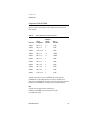
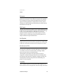
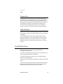
The top of the case includes a built-in handle for carrying the computer. The
handle can also be used to secure the computer using a cable and lock.
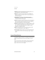
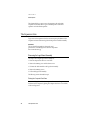
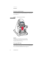
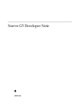
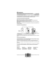
Figure 1-1 shows a front view of the computer.
Case and External Features
15
C H A P T E R
1
Introduction
Figure 1-1
Front view
Microphone
CD-ROM drive
Infrared window
Power button
on computer
Stereo speaker
Headphone jacks (2)
Stereo speaker
Apple USB
keyboard
Open button on CD-Rom drive
Power button on keyboard
Apple USB mouse
The front of the case is dominated by the 15-inch display. The front also
includes, below the display, the following features:
16
■
CD-ROM drive opening, in the center, with a drawer eject button
■
Stereo speakers, one on either side
■
Infrared window, next to the speaker on the left side
■
Two headphone jacks, next to the speaker on the right side
■
Power button, green when on, amber in Sleep mode, located between the CD
drive and the headphone jacks
Case and External Features
C H A P T E R
1
Introduction
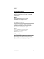
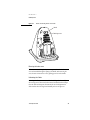
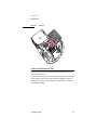
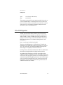
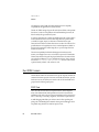
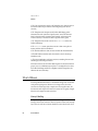
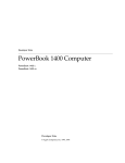
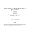
Figure 1-2
Side view showing I/O bay
Universal Serial Bus (USB) ports (2)
Ethernet port
Hole for reset button
Sound output port
Sound input port
Hole for programmer's
button (NMI)
Internal modem port
Case and External Features
17
C H A P T E R
1
Introduction
The back of the case contains the receptacle for the power cord and a small
folding handle for use in removing the access cover on the bottom of the case.
The right side of the case, as viewed from the front, contains the I/O bay behind
a hinged cover. Figure 1-2 is a side view showing the I/O bay with its cover
open.
The I/O bay contains the following features:
■
Sound input and output jacks
■
Two USB ports
■
Ethernet port
■
Modem connector
■
Access to programmer’s buttons through two small openings (upper one for
reset, lower one for NMI)
The bottom of the case has a hinged support that can be used to tilt the front of
the computer upward by about 17 degrees.
The back portion of the bottom of the case is a removable plastic cover, retained
by a screw, that can be removed to allow access to the main logic board and
drive assembly. That entire assembly can be removed for installation of
expansion RAM.
Compatibility Issues
1
While the iMac computer has many new features, there should be no
compatibility problems with applications that operate correctly with earlier
Macintosh models. Compatibility issues for expansion and peripheral devices
are listed here.
System Software
1
The iMac computer has newly designed system software that provides Open
Firmware booting and Mac OS ROM in RAM. The system software is described
in Chapter 5. For software compatibility information, see “Compatibility”
(page 59).
18
Compatibility Issues
C H A P T E R
1
Introduction
Main RAM Expansion Modules
1
For expansion of main RAM, the iMac computer uses standard SO-DIMMs that
contain SDRAM devices. These are similar to the SO-DIMMs used in the
Macintosh G3 PowerBook Series. For more information, see “Main RAM
Expansion” (page 48).
IMPORTANT
The main RAM DIMMs in the iMac must be SO-DIMMs
that use SDRAM devices. SO-DIMMs that use EDO or
SGRAM devices will not work. ▲
Video RAM Expansion Modules
1
For expansion of video RAM, the iMac computer accepts one standard
SO-DIMM that contains SGRAM devices. This is the same as the video
expansion SO-DIMMs used in the the Power Macintosh G3 computers. For
more information, see “Video RAM Expansion” (page 53).
IMPORTANT
The video RAM DIMMs in the iMac must be SO-DIMMs
that use SGRAM devices. SO-DIMMs that use EDO or
SDRAM devices will not work. ▲
USB Ports and Devices
1
The USB ports take the place of the ADB and serial I/O ports found on earlier
Macintosh computers. Software shims have been added to allow existing
applications designed to work with ADB mice and keyboards to work with the
equivalent USB devices. See “USB Compatibility Issues” (page 30).
Compatibility Issues
19
C H A P T E R
Figure 2-0
Listing 2-0
Table 2-0
2
Architecture
2
21
C H A P T E R
2
Architecture
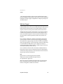
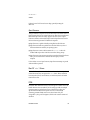
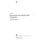
The components at the heart of the iMac computer reside on two printed-circuit
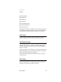
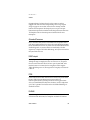
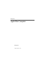
boards: the main logic board and the processor module. The Figure 2-1 is a
block diagram showing the major components on those boards. The
components shown are described in the sections that follow.
Figure 2-1
Block diagram
Processor module
Modem module
Modem
controller
RAM
SO-DIMM
RAM
SO-DIMM
512 KB
Backside
L2 cache
Datapump
Main logic board
Telephone
connector
Internal
microphone
RAM
Sound in
Burgundy
sound I/O
ROM
PowerPC
G3
microprocessor
DAA
Data
Address
Grackle
memory
controller
and PCI
bus bridge
PCI bus
Sound out
Speakers
Headphone
jack board
Paddington
I/O and
disk
controller
Internal
CD-ROM drive
Internal IDE
disk drive
IrDA board
Internal
video
monitor
Rage IIc
video
DAC
Cuda
power
manager
IC
SGRAM
ST10040
Ethernet IC
SGRAM
SO-DIMM
22
USB IC
Power switch
and LED
Ethernet
connector
USB port 1
USB port 2
C H A P T E R
2
Architecture
Processor module
2
The processor module contains the high-speed components:
■
G3 microprocessor
■
512 KB backside cache memory
■
main memory (minimum of 32 MB)
■
system ROM (1 MB)
■
memory controller and the PCI bus bridge IC
The devices on the processor module communicate with the main logic board
by way of the PCI bus.
This section includes a description of the microprocessor, the backside cache,
and the memory controller IC. For a description of the SO-DIMMs that contain
the main memory, please see Chapter 4, “Expansion.”
G3 Microprocessor
2
The latest family of PowerPC microprocessor designs is called “G3,” for
“generation three.” The G3 microprocessors have several features that
contribute to improved performance, including:
■
larger on-chip (L1) caches, 32 KB each for instruction cache and data cache
■
a built-in cache controller and cache tag RAM for the second level (L2) cache
■
a separate backside bus for the L2 cache, providing faster clock speed and
overlapped bus transactions
■
a microprocessor core optimized for Mac OS applications
The G3 microprocessor in the iMac runs at a clock speed of 233 MHz.
Backside Cache
2
The controller and tag storage for the backside cache are built into the
microprocessor chip. The cache controller includes bus management and
control hardware that allows the cache to run at a sub-multiple of the
Processor module
23
C H A P T E R
2
Architecture
processor’s clock speed, rather than at the clock speed of the main system bus.
In the iMac, the clock speed of the backside cache is half that of the
microprocessor.
The data storage for the backside L2 cache consists of 512 KB of fast static RAM
on the processor module.
Memory Controller and PCI Bridge
2
The memory controller and PCI bus bridge IC is a Motorola MPC106, also
called Grackle. The Grackle IC provides the bus bridge between the processor
bus used on the processor module and the PCI bus used for the ICs on the main
logic board. The Grackle IC also contains the memory controller for the main
memory.
The main memory bus runs at a clock speed of 66.67 MHz. The internal PCI bus
runs at 33.33 MHz. To enhance performance, the Grackle IC supports
concurrent transactions on the main memory bus and the PCI bus.
Information about the Grackle IC is available on the World Wide Web at
http://www.mot.com/SPS/PowerPC/products/semiconductor/
support_chips/106.html
Main Logic Board
2
All the I/O interfaces and the video display system are on the main logic board.
The controller ICs on the main logic board are connected to the PCI bus, which
also communicates with the processor module.
I/O Controller IC
The I/O controller IC in the Macintosh iMac computer is an ASIC called
Paddington. The Paddington IC is an integrated I/O controller and DMA
engine for use in Power Macintosh computers with a PCI bus.
The Paddington IC contains the PCI bus arbiter. It also provides the interface
and control signals for
■
24
the video display subsystem
Main Logic Board
2
C H A P T E R
2
Architecture
■
the built-in modem
■
the infrared link
■
the Ethernet port
■
the sound ASIC
■
the internal IDE hard drive
■
the internal CD-ROM drive
■
the power manager IC
The Paddington IC is similar to the Heathrow IC used in the Power Macintosh
G3 computers and Macintosh PowerBook G3 computers. The main difference is
that the Paddington IC supports 100Base-TX Ethernet as well as 10Base-T.
USB Controller
2
The USB controller is a standard IC with two USB connectors. The register set
complies with the Open Host Controller Interface (OHCI) specification.
Video Display Subsystem
2
The display subsystem consists of a graphics controller ASIC, 2 MB of SGRAM
on the main logic board, and a connector for an additional 2 MB or 4 MB of
SGRAM on an SO-DIMM. For information about the SGRAM SO-DIMM, see
Chapter 4, “Expansion.”
The graphics controller IC is an ATI Rage IIc. It contains 2D and 3D acceleration
engines, a digital video port, front-end and back-end scalers, a CRT controller,
and a PCI bus interface with bus master capability.
For information about the display and supported resolutions, see Chapter 3,
“Devices and Ports.”
Built-in Modem
2
The built-in hardware modem is a separate module that is connected to the SCC
port A of the Paddington IC. The module contains a modem controller IC, a
datapump, and the interface to the telephone line (DAA).
Main Logic Board
25
C H A P T E R
2
Architecture
Infrared Link Module
2
The infrared link module is a separate printed circuit board that is connected to
SCC port B of the Paddington IC.
The maximum IrDA data transfer rate is 4 Mbit/sec.
26
Main Logic Board
C H A P T E R
Figure 3-0
Listing 3-0
Table 3-0
3
Devices and Ports
3
27
C H A P T E R
3
Devices and Ports
This chapter describes both the built-in I/O devices and the ports for
connecting external I/O devices. Each of the following sections describes an
I/O port or device:
■
“USB Ports”
■
“Keyboard”
■
“Mouse”
■
“Hard Disk Drive”
■
“Video Display”
■
“Infrared Communication Link”
■
“Sound System”
■
“Ethernet Port”
■
“Internal Modem”
USB Ports
3
The iMac computer has two Universal Serial Bus (USB) ports that are used to
connect the keyboard and mouse as well as additional I/O devices such as
printers, scanners, and low-speed storage devices.
For more information about USB on the Macintosh computer, refer to Apple
Computer’s Mac OS USB DDK ATI Reference. Information is also available on
the World Wide Web, at:
http://developer.apple.com/dev/usb/
For full specifications of the Universal Serial Bus, refer to the USB
Implementation Forum on the World Wide Web, at:
http://www.usb.org/developers/index.html
USB Connectors
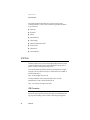
The USB ports use USB Type A connectors, which have four pins each. Two of
the pins are used for power and two for data. Figure 3-1 is an illustration of a
Type A port and matching connector. Table 3-1 shows the pin assignments.
28
USB Ports
3
C H A P T E R
3
Devices and Ports
Figure 3-1
USB Type A port and connector
Table 3-1
Pin assignments on the USB port
Pin
Signal name
Description
1
VCC
+5 VDC
2
D–
Data –
3
D+
Data +
4
GND
Ground
The iMac computer provides 5-volt power at 500 mA for each of the two ports.
The USB ports support both low-speed and high-speed data transfers, at up to
1.5 Mbits per second and 12 Mbits per second, respectively. High-speed
operations requires the use of shielded cables.
Transfer Types Supported
3
The USB specification defines four data transfer types:
■
Control transfers, used for device configuration and initialization.
■
Bulk transfers, used for printers, scanners, modems, and other devices that
require accurate delivery of data with relaxed timing constraints.
USB Ports
29
C H A P T E R
3
Devices and Ports
■
Interrupt transfers, used for human interface device (HID) class devices such
as keyboards and mice, as well as devices that report status changes, such as
serial or parallel adaptors and modems.
■
Isochronous transfers, used for on-time delivery of data. Isochronous data
transactions are best suited for audio or video data streams.
Version 1.0 of the Macintosh USB system software provides functions that
support only control, bulk, and interrupt transfer types.
USB Compatibility Issues
3
The USB ports take the place of the ADB and serial I/O ports found on earlier
Macintosh computers, but they do not function the same way. The following
sections describe the differences.
ADB Compatibility
Apple is providing an ADB/USB shim to support processes that control ADB
devices by making calls to the ADB Manager and the Cursor Device Manager.
The ADB/USB shim makes it possible for processes that support an ADB
keyboard to work with the USB keyboard equivalent.
For example, the ADB/USB shim allows applications to set the caps lock and
num lock LEDs on the Apple USB keyboard. The ADB/USB shim also allows
the Cursor Device Manager to support a USB mouse.
Keyboards other than the Apple USB keyboard can be used with the iMac
computer, but they will be treated as having an ADB device ID of 2.
IMPORTANT
The ADB/USB shim does not support other types of ADB
devices. ▲
Note
The ADB/USB shim is built into the Mac OS ROM image
on the iMac computer and will be included in the Mac OS
ROM image on future Power Macintosh systems that have
USB ports. For more information about the Mac OS ROM
image, refer to Chapter 5, “Software.” ◆
30
USB Ports
3
C H A P T E R
3
Devices and Ports
Serial Port Compatibility
3
The first release of the MacOS USB DDK does not include a universal Serial/
USB shim that would allow processes that use the Communications Toolbox
CRM to use a USB serial device. At the introduction of the iMac computer, any
USB Serial Class Driver will need to implement its own Serial/USB shim.
The first release of the Mac OS USB DDK does not include a universal Serial/
USB shim that would allow processes that use the Communications Toolbox
CRM to find and use a USB modem device. At the introduction of the iMac
computer, any USB modem device would need to implement its own
communication shim to interface between the CRM and its USB
Communication class driver. For more information, please refer to the Mac OS
USB DDK, which is available from the Apple Developer DDK page on the
World Wide Web, at
http://developer.apple.com/sdk/
Macintosh-To-Macintosh Connections
3
USB is a serial communications channel, but it does not replace LocalTalk
functionality on Macintosh computers; you cannot connect two Macintosh
computers together using the USB. The best method for networking iMac
computers is through the built-in Ethernet port.
USB Storage Devices
3
The Macintosh USB software does not support booting from an external USB
storage device.
USB Controller
3
The iMac computer uses an Open Host Controller Interface (OHCI) controller
for USB communication. Some early USB devices (most notably keyboards)
can’t interoperate with an OHCI controller. Those devices will not be supported
by the Macintosh USB system software.
USB Ports
31
C H A P T E R
3
Devices and Ports
Keyboard
3
The Apple USB keyboard has a total of 82 keys, including 12 function keys, a
numeric keypad and a set of 4 cursor-control keys. The cursor-control keys are
in the inverted-T arrangement.
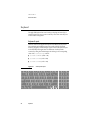
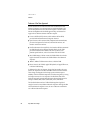
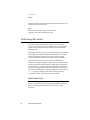
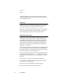
Keyboard Layout
3
There are versions of the Apple USB keyboard with different key layouts for
three standards used in different parts of the world: ANSI (US and North
America), JIS (Japan), and ISO (Europe). Figure 3-2 shows the keyboard layout
for the ANSI keyboard. Applications can determine which keyboard is
connected by calling the Gestalt Manager and checking for the corresponding
value of the gestaltKeyboardType selector:
■ gestaltUSBCosmoANSIKbd
■ gestaltUSBCosmoJISKbd
(value = 200)
■ gestaltUSBCosmoISOKbd
(value = 199)
Figure 3-2
esc
~
`
tab
caps lock
F1
!
1
A
32
F5
%
5
E
R
D
X
ANSI keyboard layout
F4
$
4
S
Z
F3
#
3
W
shift
control
F2
@
2
Q
(value = 198)
C
option
^
6
M
<
,
{
[
P
:
;
L
>
.
F11
+
=
-
O
K
F10
-
)
0
I
J
N
F9
(
9
U
H
B
F8
*
8
Y
G
V
F7
&
7
T
F
F6
help
home
pg up
pg dn
clear
=
/
*
7
8
9
-
4
5
6
+
1
2
3
num
lock
delete
}
]
"
'
?
/
F12
|
\
return
shift
0
Keyboard
.
enter
C H A P T E R
3
Devices and Ports
Keyboard and USB
3
The Apple USB keyboard is designed to work with the iMac computer by way
of the USB ports. The keyboard has a captive cable with a USB Type A
connector. The keyboard is a bus-powered USB hub with two USB Type A
ports.
▲
W AR N I N G
A bus-powered hub as defined in the USB specification
does not provide enough power to support a second
bus-powered hub. A second bus-powered hub must be
connected to the second USB port on the computer, not to a
port on the Apple USB keyboard. ▲
Power to the computer can be turned on using the keyboard power button. A
proprietary circuit allows the power control circuitry on the main logic board to
detect a power-button press and turn on the power.
The standard NMI and reset key combinations are available, but the keys are
decoded in software and may not be available under some crashed conditions.
Therefore, NMI and reset switches are also available in the computer’s I/O bay,
behind small holes (accessible by means of an unfolded paper clip).
Apple provides a HID class driver for the Apple USB keyboard, which supports
the USB boot protocol. Other keyboards intended for use on the Macintosh
platform must support the HID boot protocol, as defined in the USB Device
Class Definition for Human Interface Devices (HIDs).
Mouse
3
The Apple USB mouse is designed to work with the iMac computer by way of
the USB ports. The mouse case is round and has the same two-tone color design
as the case of the iMac computer.
Note
Despite rumours you may have heard, the Apple USB
mouse does not have an internal light source—it doesn’t
glow. ◆
Mouse
33
C H A P T E R
3
Devices and Ports
The mechanism inside the Apple USB mouse is similar to that in the Apple
Desktop Bus Mouse II. The mouse ball is removeable for cleaning; the ring that
allows access to the ball can be locked by inserting an unfolded paper clip into a
small hole and turning the ring clockwise.
Hard Disk Drive
3
The iMac computer has an internal hard disk drive. The drive uses the extended
IDE (integrated drive electronics) interface, which is also referred to as the ATA
interface. The implementation of the ATA interface on these computers is a
subset of the ATA/IDE specification, ANSI proposal X3T10/0948D, Revision 3
(ATA-3).
The software that supports the internal hard disk is the same as that in previous
Macintosh PowerBook models with internal IDE drives and includes DMA
support. For the latest information about that software, see Technote #1098, ATA
Device Software Guide Additions and Corrections, available on the world wide web
at
http://developer.apple.com/technotes/tn/tn1098.html
The web page for Technote #1098 includes a link to a downloadable copy of
ATA Device Software Guide.
Video Display
The built-in video display uses a 15-inch CRT (13.8-inch viewable diagonal).
The CRT uses shadow-mask technology and has a dot pitch of 0.28 mm. The
display is multi-scan and supports three resolutions. Table 3-2 lists the
resolutions and the pixel depths supported with either the standard 2 MB of
SGRAM or with expanded SGRAM.
34
Hard Disk Drive
3
C H A P T E R
3
Devices and Ports
Table 3-2
Display resolutions and pixel depths
Resolution
Vertical rate
Pixel depth
(2 MB SGRAM)
Pixel depth
(4 or 6 MB SGRAM)
640 by 480
117.233 Hz
32 bits
32 bits
800 by 600
94.97 Hz
32 bits
32 bits
1024 by 768
75.03 Hz
16 bits
32 bits
Infrared Communication Link
3
The iMac computer has a direct infrared (IR) communication link connected
internally to serial port B. When the computer is placed within range of another
device with an IR interface, it can send and receive serial data using the IrDA
protocol. The other device can be an IrDA-equipped Macintosh PowerBook or
some other device that complies with the Infrared Data Association (IrDA)
standard. The minimum range of the IR link is approximately 2 inches, and the
maximum range is 1 meter.
The IR link in the iMac computer supports IrDA at up to 4.0 Mbps. The IrDA
modulation method complies with the IrDA physical layer standard, which can
be found at ftp://irda.org.
Sound System
3
The 16-bit stereo audio circuitry provides high-quality sound input and output
through the built-in microphone and speakers. The user can also connect
external input and output devices by way of the sound input and output jacks.
The sound system is based on the Burgundy codec IC along with input and
output amplifiers and signal conditioners. The sound system supports sample
sizes up to 16 bits at a sample rate of 44.1 kHz.
Infrared Communication Link
35
C H A P T E R
3
Devices and Ports
Sound Inputs
3
The sound system accepts inputs from three possible sources:
■
built-in microphone
■
external stereo sound input jack
■
sound from internal CD player
Built-in Microphone
3
The sound signal from the built-in microphone goes through a dedicated
preamplifier that raises its signal level to the nominal level of the codec circuits
in the Burgundy IC.
External Sound Input
3
The external sound input jack is a 3.5-mm mini phone jack located in the I/O
bay on the right side of the computer. The sound input jack accepts line-level
stereo signals or an Apple PlainTalk microphone. It also accepts a stereo
miniplug-to-RCA cable adapter for connecting stereo equipment to the
computer.
The sound input jack has the following electrical characteristics:
■
input impedance: nominal 3300 ohms
■
maximum level: nominal 1 V rms (2.8 V peak-to-peak)
Sound Outputs
3
The sound system sends computer-generated sounds to the built-in speakers,
the sound output jack, and the headphone jacks. The sound system provides
user-selectable SRS® 3D stereo enhancement.
Internal Speakers
The computer has two internal speakers. The computer turns off the sound
signals to the internal speakers under the following conditions:
36
■
when headphones are plugged into either headphone jack
■
when a plug is inserted into the sound output jack
Sound System
3
C H A P T E R
3
Devices and Ports
■
during power cycling
External Sound Output
3
The external sound output jack is a 3.5-mm mini phone jack located in the I/O
bay on the right side of the computer. It accepts a stereo miniplug-to-RCA cable
adapter for connecting stereo equipment to the computer.
The sound output jack has the following electrical characteristics:
■
output impedance: nominal 180 ohms
■
maximum level: nominal 1 V rms (2.8 V peak-to-peak)
Headphone Jacks
3
Two headphone jacks are located on the front of the computer next to the right
speaker. Each sound output jack provides enough current to drive a pair of
low-impedance headphones.
The headphone jacks have the following electrical characteristics:
■
output impedance: nominal 13 ohms
■
maximum level: 1.4 V rms (4.0 V peak-to-peak)
Headphones should have an impedance not lower than the recommended
minimum impedance of 32 ohms. Headphones with lower impedance can be
used, but with some degradation in performance.
Sound Specifications
3
The frequency response of the sound circuits, not including the microphone and
speakers, is within plus or minus 1 dB from 4 Hz to 20 kHz.
Sound System
37
C H A P T E R
3
Devices and Ports
Total harmonic distortion plus noise (THD+N) as a percentage of full scale for
various outputs are shown in Table 3-3.
Table 3-3
Distortion specifications
Connector and level
Total harmonic distortion
and noise
Line input
0.03%
Line output
0.03%
Headphone jack, open circuit
0.03%
Headphone jack, 32-ohm headphones,
–20 dBFS level
0.1%
Headphone jack, 32-ohm headphones,
–1.5 dBFS level
1.0%
The signal-to-noise ratios (SNR) for various inputs and outputs are shown in
Table 3-4. The values shown are unweighted; values with A weighting would
be about 8 dB higher.
Table 3-4
38
Noise specifications
Connector and level
Signal-to-noise ratio
Line output
92 dB
Headphone jacks
86 dB
Line input
85 dB
Internal CD
82 dB
Sound System
C H A P T E R
3
Devices and Ports
Ethernet Port
3
The iMac computer has a built-in 10/100 Mbps Ethernet port. The user can
connect it to either a 10Base-T or a 100Base-TX hub; the port will automatically
sense which type of hub is connected.
The connector for the Ethernet port is a an RJ-45 connector in the I/O bay on
the right side of the computer.
The Ethernet interface in the iMac computer conforms to the ISO/IEC 802.3
specification, where applicable.
Internal Modem
3
The iMac computer comes with a built-in modem. The connector for the
modem is an RJ-11 connector in the I/O bay on the right side of the computer.
The modem has the following features:
■
modem bit rates up to 56 Kbps (supports K56flex and V.90 modem
standards)
■
fax modem bit rates up to 14.4 Kbps
The modem appears to the system as a serial port that responds to the typical
AT commands. The modem provides a sound output for monitoring the
progress of the modem connection.
Ethernet Port
39
C H A P T E R
Figure 4-0
Listing 4-0
Table 4-0
4
RAM Expansion
4
41
C H A P T E R
4
RAM Expansion
This chapter tells how to gain access to the expansion slots in the iMac
computer and describes the two types of RAM expansion: main RAM
expansion and video RAM expansion.
The Expansion Slots
4
To get access to the expansion slots, the user must open up the bottom of the
computer and remove the main logic board and processor module assembly.
IMPORTANT
The user should be reminded to observe the usual
precautions to avoid damage to the electronic components
due to static electricity. ▲
Removing the Logic Board Assembly
4
The steps in removing the logic board assembly are:
1. Place the computer face down on a soft cloth.
2. Remove the retaining screw and the bottom cover.
3. Unfasten the cables attached to the logic board assembly.
4. Remove the retaining screws.
5. Pull out the logic board assembly.
The following sections describe the steps.
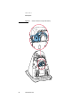
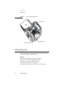
Placing the Computer Face Down
To remove the logic board from the computer, the user must first gain access to
the bottom of the computer by placing the computer face down on a soft cloth,
as shown in Figure 4-1.
42
The Expansion Slots
4
C H A P T E R
4
RAM Expansion
Figure 4-1
Bottom view showing bottom cover handle
Handle
Retaining screw
Removing the bottom cover
4
The bottom cover is held in place by a retaining screw located on the bottom
cover and accessible through the opening in the handle. After removing the
screw, the user can remove the cover by pulling up and out on the handle.
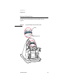
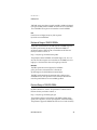
Unfastening the Cables
4
Several signal cables are connected to the back of the logic board assembly, as
shown in Figure 4-2. Those must be disconnected and freed from their clamps.
Once the cables and clamps are disconnected, the user should position the
cables to either side of the logic board assembly, as shown in Figure 4-3.
The Expansion Slots
43
C H A P T E R
4
RAM Expansion
Figure 4-2
44
Cables connected to the logic board assembly
The Expansion Slots
C H A P T E R
4
RAM Expansion
Removing the Retaining Screws
4
A slot-shaped handle is located at the back end of the logic board assembly. The
retaining screws are located inside the slot in the handle, as shown in
Figure 4-3.
Figure 4-3
Logic board assembly handle and retaining screws
Handle
Retaining screws
The Expansion Slots
45
C H A P T E R
4
RAM Expansion
Removing the Logic Board Assembly
4
With the retaining screws removed and the cables positioned to the sides, the
user can remove the logic board assembly by pulling upward on the handle, as
shown in Figure 4-4.
Figure 4-4
Removing the logic board assembly
IMPORTANT
While removing and reinstalling the logic board assembly,
you should take care to align the door of the CD drive with
the opening in the front of the case. ▲
Removing the EMI Shield
4
Once the logic board assembly is free of the case, you can see the EMI shield,
which covers the processor module. To gain access to the main RAM expansion
slots, you must remove the EMI shield, as shown in Figure 4-5.
46
The Expansion Slots
C H A P T E R
4
RAM Expansion
Figure 4-5
EMI shield
Locations of the Expansion Slots
4
Figure 4-6 shows the location of the two main RAM expansion slots and the
video RAM expansion slot.
One of the main RAM expansion slots is on the bottom of the processor module
and is normally occupied by the factory-installed SO-DIMM. The other main
RAM expansion slot is on the top of the processor module and is available for a
user-installed SO-DIMM.
The Expansion Slots
47
C H A P T E R
4
RAM Expansion
Figure 4-6
Locations of the RAM expansion slots
Video RAM slot
Main RAM top slot
Main RAM bottom slot
Main RAM Expansion
The iMac computer has two RAM expansion slots that accommodate standard
SO (small outline) DIMMs using SDRAM devices.
IMPORTANT
RAM expansion SO-DIMMs for the iMac must use SDRAM
devices. If the user installs an SO-DIMM that uses EDO or
SGRAM devices, the computer will beep several times
when the user attempts to restart the computer. ▲
An SO-DIMM for the iMac can contain either 16, 32, or 64 MB of memory.
48
Main RAM Expansion
4
C H A P T E R
4
RAM Expansion
Total RAM capacity using devices currently available is 128 MB and is limited
by the space available for the SO-DIMMs. The bottom slot can accommodate a
1.5-inch SO-DIMM. The top slot can accommodate a 2.0-inch SO-DIMM.
Note
Future devices with higher density may allow expansion
beyond the current 128-MB limit.
Mechanical Design of RAM SO-DIMMs
4
The mechanical characteristics of the RAM expansion SO-DIMM are given in
the JEDEC specification for the 144-pin 8-byte DRAM SO-DIMM. The
specification number is JEDEC MO-190; it is available from the Electronics
Industry Association’s web site, at
http://www.jedec.org/download/freestd/pub95/
The specification defines SO-DIMMs with nominal heights of 1.0, 1.25, 1.5, or
2.0 inches. The iMac computer can accommodate two SO-DIMMS, one with a
height up to 1.5 inches and the other with a height up to 2.0 inches.
IMPORTANT
The JEDEC specifications for the heights of the SO-DIMMs
gives a plus-or-minus 0.15 mm tolerance. In the iMac, the
specified heights for the SO-DIMMs are maximum heights.
The JEDEC specification defines the maximum depth or thickness of an
SO-DIMM as 3.8 mm. That specification is also a maximum: Modules that
exceed the specified thickness can cause reliability problems.
Electrical Design of RAM SO-DIMMs
4
The electrical characteristics of the RAM SO-DIMM are given in section 4.5.6 of
the JEDEC Standard 21-C, release 7. The specification is available from the
Electronics Industry Association’s web site, at
http://www.jedec.org/download/jep21-j.pdf
The specification defines several attributes of the DIMM, including storage
capacity and configuration, connector pin assignments, and electrical loading.
The specification supports SO-DIMMs with either one or two banks of memory.
Main RAM Expansion
49
C H A P T E R
4
RAM Expansion
The JEDEC specification for the SO-DIMM defines a Serial Presence Detect
(SPD) feature that contains the attributes of the module. SO-DIMMs for use in
the iMac are required to have the SPD feature. Information about the required
values to be stored in the presence detect EEPROM is in section 4.1.2.5 and
Figure 4.5.6–C (144 Pin SDRAM SO–DIMM, PD INFORMATION) of the JEDEC
standard 21-C specification, release 7.
Because the SO-DIMM connector has only two clock lines, and each clock line is
limited to only 4 loads, an SO-DIMM with more than 8 SDRAM devices must
have buffers on the clock lines. The buffers must be zero-delay type, such as
phase-lock loop (PLL), which regenerates the clock signals. For example, the
computer can support a 128-MB SO-DIMM using 16 devices and a PLL clock
buffer.
SDRAM Devices
4
The SDRAM devices used in the RAM expansion modules must be self-refresh
type devices for operation from a 3.3-V power supply. The speed of the SDRAM
devices must be 100 MHz or greater, corresponding to a cycle time of 10 ns or
less.
The devices are programmed to operate with a CAS latency of 3. At that CAS
latency, the access time from the clock transition must be 7 ns or less. The burst
length must be at least 4 and the minimum clock delay for back-to-back random
column access cycles must be a latency of 1 clock cycle.
50
Main RAM Expansion
C H A P T E R
4
RAM Expansion
Configuration of RAM SO-DIMMs
4
Table 4-1 shows the sizes of the RAM expansion modules that can be used in
the iMac computer and the different sizes of SDRAM devices that make up
those modules.
Table 4-1
Sizes of RAM expansion modules and devices
Device size
Device
configuration
Number of
devices
per bank
Size of
each bank
16 Mbits
2M x 4 x 2
16
32 MB
16 Mbits
1M x 8 x 2
8
16 MB
16 Mbits
512K x 16 x 2
4
8 MB
64 Mbits
8M x 4 x 2
16
128 MB
64 Mbits
4M x 4 x 4
16
128 MB
64 Mbits
4M x 8 x 2
8
64 MB
64 Mbits
2M x 8 x 4
8
64 MB
64 Mbits
2M x 16 x 2
4
32 MB
64 Mbits
1M x 16 x 4
4
32 MB
64 Mbits
1M x 32 x 2
2
16 MB
64 Mbits
512K x 32 x 4
2
16 MB
The iMac accepts either one or two SO-DIMMs. Any of the supported
SO-DIMM sizes can be installed in either slot, subject to the limits on the
dimensions of the SO-DIMMS. The memory controller configures the combined
memory of the SO-DIMMs into a contiguous array of memory addresses.
Note
The iMac does not support memory interleaving, so
installing two SO-DIMMs of the same size does not result
in any performance gain.
Main RAM Expansion
51
C H A P T E R
4
RAM Expansion
Address Multiplexing
4
Signals A[0] – A[13] on each RAM SO-DIMM make up a 14-bit multiplexed
address bus that can support several different types of SDRAM devices. Table
4-2 lists the types of devices that can be used in the iMac computer by size,
configuration, and sizes of row and column addresses.
IMPORTANT
The iMac supports only the types of SDRAM devices
specified in Table 4-2. Other types of DRAM devices should
not be used with this computer. ▲
Table 4-2
Types of DRAM devices
Device size
Device
configuration
Size of
row
address
Size of
column
address
16 Mbits
2M x 4 x 2
11
10
16 Mbits
1M x 8 x 2
11
9
16 Mbits
512K x 16 x 2
11
8
64 Mbits
8M x 4 x 2
13
10
64 Mbits
4M x 4 x 4
12
10
64 Mbits
4M x 8 x 2
13
9
64 Mbits
2M x 8 x 4
12
9
64 Mbits
2M x 16 x 2
13
8
64 Mbits
1M x 16 x 4
12
8
64 Mbits
1M x 32 x 2
13
7
64 Mbits
512K x 32 x 4
12
7
RAM SO-DIMM Electrical Limits
Each RAM SO-DIMM must not exceed the following maximum current limits
on the +3 V supply:
52
Main RAM Expansion
4
C H A P T E R
4
RAM Expansion
Active
1.2 A (8 devices at 150 mA each)
Sleep
6 mA per bank
The maximum current specified for active operation generally rules out the use
of 4-bit-wide SDRAM devices in a RAM expansion card. Such a card would
have 16 such devices, and the 1.2 A maximum current would allow only about
75 mA per device. To stay within the current limits, RAM expansion cards
should use only 8-bit or 16-bit SDRAM devices.
Video RAM Expansion
4
The iMac computer includes 2 MB of SGRAM for video on the main logic
board. The video RAM can be expanded up to 6 MB with an additional 2 or
4 MB of SGRAM on a 144-pin SO-DIMM (small outline dual inline memory
module). The mechanical design of the SGRAM SO-DIMM is defined by the
JEDEC MO-190 specification. The SGRAM SO-DIMM specification can be
downloaded at
http://www.jedec.org/download/freestd/pub95/
The devices on the DIMM must be 3.3 V SGRAM devices. The speed of the
SGRAM devices must be 100 MHz or greater, corresponding to a cycle time of
10 ns or less. The 100 MHz/10ns SGRAM SO-DIMM specification provides
suitable margins for compatibility with the iMac architecture.
Increasing the size of the installed video RAM from 2 MB to 4 or 6 MB increases
the maximum color depth available at the highest monitor resolutions.
Any additional video RAM that isn’t used for the current display mode is
available to QuickDraw 3D applications for more data storage, such as textures,
which results in faster 3D graphics performance. A more detailed explanation of
video RAM and QuickDraw 3D graphics performance can be found in Chapter
5 of the Power Macintosh 5500/6500 Developer Note, where the use of the video
frame buffer for front frame buffer, back frame buffer, optional Z buffer, and
available texture memory are described.
Video RAM Expansion
53
C H A P T E R
Figure 5-0
Listing 5-0
Table 5-0
Software
5
5
55
C H A P T E R
5
Software
The Apple iMac computer is different from previous Macintosh computers in
that it has no single, large ROM that contains the toolbox software, the 68K
emulator, hardware initialization, and the nanokernel. A small ROM provides
hardware initialization functions and provides a mechanism to load the Mac OS
Toolbox ROM image into RAM. The new software architecture that is centered
around ROM-in-RAM and its ramifications has the code name NewWorld.
Why Make This Change?
5
Historically, the Macintosh ROM has been structured as one monolithic ROM,
known as the ToolBox ROM, that contains both low level and high level
software. That is, the ROM contains the hardware-specific code needed by the
computer at power-up time as well as higher level Mac OS ToolBox software.
Examples of hardware-specific code are drivers, feature tables, diagnostics, and
hardware initialization code. Examples of higher level software are high-level
ToolBox managers, QuickDraw, SCSI Manager, and so on.
As features have been added to the Mac OS software, some of the higher level
code expanded beyond the practical limits provided by ROMs, so the ROM has
been augmented and modified by system software such as the System file and
the Enabler. In this way the functionality of the ROM has been spread out
among the ROM, the Enabler, and disk-based system software. This
intertwining of low-level and high-level code spread out from ROM to disk has
made it difficult and time consuming to release new computers.
One way to address this problem is to separate the system software into two
logically distinct pieces. One piece holds most of the hardware-specific
components needed to boot the computer, while the other contains boot-time
ToolBox routines and components that are common to many Macs. With this
scheme, much of the hardware-specific code is isolated in the Boot ROM, and
the ToolBox and system software code can be made abstract and generic. This
approach has several benefits.
• When hardware changes are needed, only the hardware-specific code in the
Boot ROM has to be modified, greatly decreasing turnaround time for new
product releases, and reducing testing time and expenses.
• The high-level ToolBox and system software does not need to change often.
When making a new build as a result of changing hardware-dependent code,
there is high confidence that the high-level software has not been changed.
56
Why Make This Change?
C H A P T E R
5
Software
• Not changing the higher level software as often simplifies things for many
groups inside Apple, including testing, system software, software configuration
management, developer support, and publications. Third-party developers can
also benefit from this.
What Has Changed
5
Hardware-specific code that performs the computer’s start-up activities resides
in firmware (ROM). That code fits into one ROM called the Boot ROM. The Boot
ROM includes the hardware specific code and tables needed to start up the
computer, to load an OS, and to provide common hardware access services.
All higher level software resides somewhere else. For now, think of it residing
in what has been historically known as the Mac OS ToolBox ROM, but with
much of the old hardware-specific code moved into the Boot ROM. As before,
the ToolBox ROM can still be augmented by Enablers, the System file, and
extensions.
Prior to the iMac, all Macintosh computers required a ROM component that
contained the Mac OS Toolbox software. The NewWorld approach sidesteps
this requirement by copying an image of the Mac OS ToolBox into RAM before
the Mac OS begins operation. The area of RAM that contains the ToolBox image
is excluded from the available memory space in RAM, and is marked as
read-only. Once the Mac OS begins operation, a ToolBox image in RAM and an
actual ToolBox ROM behave in the same way.
No new or different software interfaces are directly accessible from Mac OS.
During the boot process, software contained in the Mac OS ToolBox ROM file
communicates with Open Firmware to collect information about the hardware,
using the Open Firmware Client Interface.
Note
Open Firmware is a central component of the NewWorld
architecture. For reference material about Open Firmware,
see “Open Firmware” (page 11). ◆
Most of the changes are completely transparent to Mac OS. Only the Startup
Disk control panel is affected: it includes added code to modify the Open
Firmware’s configuration variables in the NV-RAM.
Why Make This Change?
57
C H A P T E R
5
Software
Features of the New Approach
5
Because the iMac has new hardware features that are different from other
Macintosh computers, new software features are needed in addition to the
NewWorld requirements for other Macintosh computers. This list includes
features that implement the NewWorld approach along with features that
support the new hardware features of the iMac computer.
■
Power-on Self Test (POST) software, which resides in the Boot ROM,
provides hardware initialization and diagnostic functions.
■
Open Firmware, which resides in ROM, completes hardware initialization,
provides a description of the hardware, loads initial OS software, and
transfers control to that software.
■
Run-Time Abstraction Services (RTAS), which resides in ROM, is instantiated
into RAM through an Open Firmware method called by the OS. RTAS
provides functions that are available to the OS at any time to access
platform-specific hardware, such as the real-time clock and NV-RAM.
■
Mac OS ROM image, a file that contains the ToolBox ROM code and other
high-level software that resides in the ToolBox ROM on other Macintosh
computers.
■
10Base-T/100Base-TX Ethernet device driver, in the Boot ROM.
■
Device driver for the USB hub, Apple USB keyboard, and Apple USB mouse,
in the Mac OS ROM image.
In addition to the above new features, changes have been made to the source
base for the components of the Mac OS ROM to abstract it from the hardware.
These changes are designed to reduce bring-up time and effort, improve
reliability of the Mac OS ROM components, and reduce testing time, by moving
the changes necessary for a new computer to the Boot ROM. Some of the
hardware components accessed through this new abstracted software are the
interrupt controller, ADB, USB, SCSI, ATA (IDE), sound, and Ethernet.
The NewWorld architecture has a ToolBox ROM image that is high-level
enough to be used on many different Macintosh computers. Although the iMac
is the first Macintosh computer to use it, this new architecture is intended for
use on all future Macintosh computers.
58
Why Make This Change?
C H A P T E R
5
Software
Performance
5
Performance of an iMac computer using ROM in RAM should exceed
performance measurements for other Macintosh computers with comparable
CPUs and speeds due to improved interrupt handling with the New World
approach. In addition, performance is improved due to executing code that
normally exists in ROM in RAM, because the RAM devices operate faster than
the ROM devices normally used.
RAM Footprint
5
The iMac is the first Macintosh computer to have its Toolbox ROM image stored
in RAM. This removes approximately 3 megabytes of RAM from Mac OS usage.
In effect, a system with 32 megabytes of RAM appears to have only 29
megabytes available. Some portion of the missing 3 megabytes is offset by
having fewer patches in RAM. Other mechanisms are being explored in an
attempt to minimize the impact of ROM-in-RAM.
User Experience
5
Setting the boot volume from the Startup Disk control panel makes all the
changes to the boot process that are necessary to operate with a ToolBox image
in RAM. The control panel user interface remains unchanged for this release.
Data Structures and Files
5
The ToolBox ROM image is contained in a new file, named “Mac OS ROM”,
that is kept in the System Folder. The ToolBox ROM image is exactly the same
as it would be if it were an actual ToolBox ROM, containing the ToolBox
software, the kernel software, and the 68K emulator.
The Startup Disk control panel sets the Open Firmware’s boot-device
configuration variable by modifying the Open Firmware NV-RAM partition
that contains the Open Firmware’s configuration variables. The format of the
NV-RAM partition is defined in the Open Firmware CHRP Binding. The
partition is accessed using RTAS.
Compatibility
5
A Mac OS ToolBox image that is in write-protected RAM will appear to be a
ROM to all MacOS software and applications. Because the image of the ToolBox
Why Make This Change?
59
C H A P T E R
5
Software
in RAM appears to be a ROM, the ROM-in-RAM approach is completely
compatible with all application and system software.
The Mac OS ToolBox image is kept in a file in the System Folder on the specified
boot device. In order to avoid problems with internationalizing the name, the
file is located by file type instead of by name.
In order for Open Firmware to retrieve the ToolBox image file, it must be able to
read the selected boot device. If the ToolBox image file is on a partition that is
on a RAID, encrypted, striped, or otherwise non-standard device, Open
Firmware must be able to read from these devices in order to boot Mac OS. Two
possible solutions to this problem are to have a standard partition available on
the device that contains the ToolBox image file, or to provide Open Firmware
methods to read the file.
The main incompatibility that ROM-in-RAM approach introduces is that
memory is not mapped one-to-one, as it has been for previous PCI-based Macs.
Software that assumes the logical and physical addresses are the same will fail,
even when Virtual Memory is not on. Well-behaved software—that is, software
that calls the LogicalToPhysical or PrepareMemoryForIO functions when it needs
a physical memory address—will continue to work.
Boot ROM Contents
5
The Boot ROM contains the code needed to start up the computer, initialize and
examine the hardware, provide a device tree to describe the hardware, provide
hardware access services (RTAS), and control to the OS. The Boot ROM can be
grouped into the following major pieces.
POST Code
5
This is the code executed when the computer first boots. This encompasses
many of the traditional Mac ROM operations and is based on the hardware
initialization code used in the past: setup and initialization of the processor and
ASICs, a boot beep, an error beep, diagnostics, and transfer to Open Firmware.
A small debugging Mini-Nub is part of this section. It allows prodding and
poking with some MacsBug-like commands. Getting into the Debugger Nub is
not possible using standard user interface input, however.
60
Boot ROM Contents
C H A P T E R
5
Software
Failure to boot in POST causes the error beep, optionally entering the
Mini-Nub.
Open Firmware
5
The Open Firmware component of NewWorld is based on the CHRP version of
Open Firmware, also known as Open Firmware 3.0. This is the most robust and
full-featured Open Firmware used by Apple to date. This version of Open
Firmware contains several notable changes from the Open Firmware found in
the first and second generation PCI Macintosh computers:
■
Open Firmware is capable of reliably reading files from block devices.
■
Open Firmware builds an expanded device tree that holds every facet of
hardware information needed by an operating system.
■
Open Firmware contains code that mimics the StartSearch code in the
ToolBox ROM and provides a Mac-like user interface during startup.
■
Open Firmware creates an interrupt tree that is interlaced through the Device
Tree to provide a mechanism to describe the interrupt layout of the
computer.
If a boot failure occurs in Open Firmware, Open Firmware attempts to provide
a Macintosh-like experience.
Mac OS 'ndrv' Drivers
5
The Boot ROM may also contain Mac OS drivers that are hardware-specific and
needed at boot time; they are organized as 'ndrv' drivers. Drivers needed at
boot time (video drivers, network drivers, or disk drivers) need to be loaded
from the Device Tree.
RTAS
5
RTAS (Run-Time Abstraction Services) can be thought of as a BIOS. RTAS code
handles hardware accesses needed by an OS, making it possible for multiple
operating systems to get hardware services without having to know the
specifics. RTAS handles hardware-specific services such as NV-RAM
(containing parameter RAM), time services (the real time clock), PCI
configuration cycles, power management, and the code needed to restart and
shutdown.
Boot ROM Contents
61
C H A P T E R
5
Software
RTAS is relocateable code; its location in RAM is determined by the OS, and it
remains functional after the OS boots.
Note
RTAS is part of the system software. It is not needed by
applications, which use operating system APIs. ◆
Toolbox Image File Contents
5
The Toolbox image file (also called the bootinfo file) contains three main
components, each of which is made up of smaller components: the pieces that
are part of the bootinfo specification, the Trampoline code, and the ToolBox
ROM Image itself.
Most changes needed for a new CPU occur in the Boot ROM, not in the bootinfo
file. Changes to the ToolBox ROM Image should be limited to new manager
software and support for hardware that is common to many Macintosh
computers (ATA interface modules, user interface modules, and the like).
The bootinfo file exists on the boot device and has a localizable name.
Identification information that leads to the file’s path is stored in NV-RAM and
the search algorithm for a usable bootinfo file parallels the search mechanism
across SCSI, ATA, etc., used in the former startup disk routine. By default, the
file is located by using the directory ID of the “blessed folder” in the boot block
of each HFS or HFS Plus partition, and then searching for a file with a file type
of 'tbxi'. Searching by file type is done to allow localization of the file.
Non-localized, the name of the bootinfo file is “Mac OS ROM”.
Open Firmware Script
The bootinfo components normally do not need to be changed for each new
product. The Open Firmware script is automatically modified at build time to
have the correct offsets within the bootinfo file to the other two main
components.
62
Toolbox Image File Contents
5
C H A P T E R
5
Software
Trampoline Code
5
The Trampoline code is the component of the NewWorld architecture that
handles the transition between Open Firmware and the ToolBox ROM Image. It
retrieves all necessary information about the system from Open Firmware,
instantiates RTAS, decompresses the ToolBox ROM Image, locates the Mac OS
NV-RAM partition, formats the system information into tables and data
structures for Mac OS, terminates Open Firmware, moves information in
memory to safe locations, and transfers control to the ToolBox ROM Image.
ToolBox ROM Image
5
The NewWorld version of the ToolBox ROM Image is similar to the old ToolBox
ROM in that it has a similar layout and contains many of the same components
as it did before.
The ToolBox ROM Image includes code that contains hardware-specific
support, including ADB, VIA, Cuda/Egret, MESH SCSI, Heathrow/CHRP/
UltraDMA ATA AIMs. In the future, they can be moved out of the ToolBox
ROM Image when there is a mechanism to load them from a boot volume at
boot time.
NewWorld Boot Process
5
Following is a high level view of the execution path take when a
NewWorld-based computer boots.
1. The POST code runs (preliminary diagnostics, boot beep, initialization, and
setup), with possible intervention in the Mini Nub.
2. Open Firmware initializes and begins execution, including building the
device tree and the interrupt trees;
3. Open Firmware loads the Toolbox image file, based on defaults and NV-RAM
settings;
4. Open Firmware executes the Forth script in the bootinfo file, which contains
instructions to read both the Trampoline code and the compressed ToolBox
ROM Image and place them into a temporary place in memory;
NewWorld Boot Process
63
C H A P T E R
5
Software
5. The Forth script transfers control to the Trampoline code, which functions as
the transition between Open Firmware and the beginning of the Mac OS
execution;
6. The Trampoline code decompresses the ToolBox ROM Image, gathers
information about the system from Open Firmware, creates data structures
based on this information, terminates Open Firmware, and rearranges the
contents of memory to an interim location in physical memory space;
7. The Trampoline code transfers control to the HardwareInit routine in the
ToolBox ROM Image;
8. The HardwareInit routine copies data structures to their correct places in
memory, and then calls the NanoKernel;
9. The NanoKernel fills in its data structures and then calls the 68K Emulator;
10. The 68K Emulator initializes itself, then transfers control to the startup
initialization code;
11. The startup initialization code begins execution, initializing data structures
and Managers, and booting the Mac OS.
All functions found in the old ToolBox ROM are present in the NewWorld boot
process, but occur at different times and places. To accomplish this, the code in
the ToolBox ROM Image and POST is simplified, while the Trampoline code
addresses the new functionality.
What Is Different
5
Even though ROM-in-RAM involves a fundamental change to the construction
of the product-specific part of the Mac OS, the changes in the code and its
execution are not that large. Many components are in changed locations, but
their functions with respect to boot time and run time have not greatly changed.
Many Mac OS components remain untouched.
Interrupt Handling
5
Interrupt handling is very different with the NewWorld approach. The
interrupt code has been rewritten to allow for dynamic creation of the interrupt
layout. The new code has two features that did not exist in the old code. One is
64
What Is Different
C H A P T E R
5
Software
that interrupt latency has been reduced to such an extent as to make it
negligible. The other is that the interrupt handling code no longer requires
changes to support a new machine, unless it has new interrupt controller
hardware. The description of the interrupt layout is now part of an Open
Firmware interrupt tree that is interlaced within the Open Firmware device tree.
The Trampoline code uses this interrupt tree to build the Mac OS native
interrupt tree.
Outmoded Resources
5
Prior to NewWorld, many resources in the ROM exist in the System Folder as
well, often as replacements that fix or enhance those in the ROM, but sometimes
because the ROM resources have not yet been removed from the ROM. With the
NewWorld approach, any resources that are not needed early in the boot
sequence are no longer in the ToolBox ROM Image, and only the resources from
the System Folder are in use.
RAM Footprint
5
NewWorld puts the ToolBox ROM Image in RAM, and marks it read-only.
Although the image is 4 megabytes in size, not all of it is in use. The portion
that is not used is returned to Mac OS for use as part of system RAM. At the
time this document was written, less than 3 megabytes of the 4 megabyte
ToolBox ROM Image are in use, allowing more than 1 megabyte to be returned
to Mac OS.
RTAS
5
Certain hardware devices differ from machine to machine, but provide similar
functions. RTAS ( Run-time Abstraction Services) provides such
hardware-specific functions, including functions for accessing the real-time
clock, non-volatile RAM (NV-RAM), restart, shutdown, and PCI configuration
cycles. The I/O primitives for these functions in the ToolBox ROM Image for
NewWorld use RTAS.
NV-RAM
5
Instead of using hard-coded offsets to locations in NV-RAM for Mac OS
NV-RAM and other information, the Trampoline code breaks NV-RAM into
What Is Different
65
C H A P T E R
5
Software
variable-sized partitions that are used by Mac OS, Open Firmware, and any
other client. PRAM resides in the Mac OS partition. The partitioning scheme is
part of the CHRP specification.
NanoKernel
5
The previous version of the NanoKernel has code that is processor-specific to
create data structures. Under NewWorld, the Trampoline code creates these
data structures from information in the Open Firmware Device Tree.
NanoKernel is typically no longer changed to support a new CPU. Support for
new processors has moved to POST, which is responsible for configuring all
processor-specific registers. Run-time cache control is part of RTAS.
Startup Disk Control Panel
5
Open Firmware now bears responsibility for locating a startup device. This is
very different from previous Mac OS systems where the Mac OS ROM had
responsibility for locating the startup device. On the iMac computer, the Mac
OS ROM image itself comes from the startup disk, so decisions regarding
startup device must be made earlier in the startup process. Open Firmware
recreates as much as possible the user experience of earlier systems but the
implemention is very different.
Previous systems stored the user's selected startup device in PRAM. The startup
device was set in PRAM when the user selected a device in the Startup Disk
control panel. This device was honored by the Mac OS ROM unless the selected
device was unavailable or was overridden by the user.
The startup disk routine for the iMac, rather than setting Mac OS PRAM, sets an
Open Firmware config variable called boot-device. This setting is honored by
Open Firmware unless the selected device was unavailable or was overridden
by the user.
The following keys can be used to override the selected startup device.
66
■
Key combination Command-Option-Shift-Delete: ignore the boot-device
setting and scan for alternate devices.
■
C key: force the internal CD-ROM drive to be the startup device
■
D key: force the internal hard disk to be the startup device
What Is Different
C H A P T E R
5
Software
Once Open Firmware locates a startup device and successfully loads a Mac OS
ROM, image it passes information about the chosen device in the bootpath
variable. This information, rather than that previously set in PRAM, is
subsequently used by the Mac OS ROM to locate the device containing the
startup System Folder.
IMPORTANT
The previous API for controlling the startup device
selection, using _GetDefaultStartup and
_SetDefaultStartup, is not effective on the iMac. ▲
Open Firmware and the Device Tree
5
NewWorld relies heavily on a functioning Open Firmware with a complete
device tree.
Interrupt Layout
5
The interrupt layout is determined by information in the device tree. An
interrupt tree overlays the other information in the device tree to describe how
the interrupts are configured. The Trampoline code traverses this device tree
interrupt tree and builds data structures that are used to dispatch interrupts.
The device tree interrupt tree is defined in the Open Firmware Recommended
Practice: Interrupt Mapping. It is not necessary to change any of the interrupt
dispatching code, either 68K or native. All the necessary information is
retrieved from the device tree.
This interrupt dispatch code has drastically reduced latency times as compared
to all previous PCI Macintosh computers.
Machine Identification
5
Applications can find out which machine they are running on by calling the
Gestalt Manager. The gestaltMachineType value returned for the iMac is 406
(196 hexadecimal).
Because NewWorld uses the same Universal and ProductInfo tables for all
computer models that it runs on, those computers all have the same Box Flag.
All those computers use the same enablers, and no patches are made to the
What Is Different
67
C H A P T E R
5
Software
ToolBox ROM Image, so sharing the same Box Flag is not an issue for those
areas.
IMPORTANT
Programs such as control panels and installers that use Box
Flag to verify that this is a valid CPU on which to execute
need to be changed to verify the existence of the hardware
they require. Developers should look for the features they
need, rather than reading the Box Flag and then making
assumptions about the computer’s features. ▲
Asset management software that reports the kind of machine it is run on should
check the name registry for the value of the property at
Devices:device-tree:model. For the current iMac, the property value is iMac,1.
68
What Is Different
A P P E N D I X
Figure A-0
Listing A-0
Table A-0
Abbreviations
A
Standard units of measure used in this note include:
A
amperes
MB
megabytes
dB
decibels
Mbps
megabits per second
GB
gigabytes
Mbit
megabits
Hz
hertz
MHz
megahertz
KB
kilobytes
mm
millimeters
kg
kilograms
ns
nanoseconds
kHz
kilohertz
V
volts
mA
milliamperes
VDC
volts direct current
Other abbreviations used in this note include:
$n
hexadecimal value n
10Base-T
an Ethernet standard for data transmission at
10 Mbits per second
100Base-TX
an Ethernet standard for data transmission at
100 Mbits per second
68K
the 68000 family of microprocessors
ADB
Apple Desktop Bus
AIM
ATA Interface Module
ANSI
American National Standards Institute
API
application programming interface
ASIC
application-specific integrated circuit
ATA
AT attachment
BIOS
basic input/output system
CAS
column address strobe, a memory control signal
CD
compact disc
CD-ROM
compact disc read-only memory
69
A P P E N D I X
A
Abbreviations
70
CHRP
Common Hardware Reference Platform
CPU
central processing unit
CRM
Communications Resource Manager
CRT
cathode ray tube, a video display device
DAA
data access adapter (a telephone line interface)
DAC
digital-to-analog converter
DIMM
Dual Inline Memory Module
DMA
direct memory access
EDO
extended data out
EEPROM
electrically eraseable programmable ROM
G3
Generation 3, the third generation of PowerPC
microprocessors, including the PPC 740 and PPC 750
GND
ground
HFS
hierarchical file system
HID
human interface device, a class of USB devices
IC
integrated circuit
IDE
integrated device electronics
IEC
International Electrotechnical Commission
I/O
input and output
IR
infrared
IrDA
Infrared Data Association
ISO
International Organization for Standardization
JEDEC
Joint Electron Device Engineering Council
JIS
Japanese Industrial Standards
L1
level 1 or first level, a type of CPU cache
L2
level 2 or second level, a type of CPU cache
LED
light emitting diode
Mac OS
Macintosh Operating System
MESH
the name of an Apple custom IC
modem
modulator-demodulator, a data communications interface
for use with analog telephone lines
A P P E N D I X
A
Abbreviations
NMI
nonmaskable interrupt
NV-RAM
nonvolatile random-access memory
OHCI
Open Host Controller Interface
OS
operating system
PCI
Peripheral Component Interconnect, an industry-standard
expansion bus
PLL
phase-locked loop
POST
power-on self test
RAM
random-access memory
RAID
random array of inexpensive disks
RCA
Radio Corporation of America
rms
root mean square
ROM
read-only memory
RTAS
run-time abstraction services
SCC
Serial Communications Controller
SCSI
Small Computer System Interface
SDRAM
synchronous dynamic RAM
SGRAM
synchronous graphics RAM; used for display buffers
SNR
signal to noise ratio
SO-DIMM
small outline dual inline memory module
SPD
Serial Presence Detect, a feature of the SO DIMM
USB
Universal Serial Bus, an industry-standard
expansion bus
VCC
positive supply voltage (voltage for collectors)
VIA
versatile interface adapter
71
Index
A
F
ATA Device Software Guide 10, 34
ATA disk interface 34
ATA hard disk 34
ATI Rage IC 25
features list 14
B
backside cache 23
Boot ROM 57
contents 60–62
Box Flag 68
G
G3 microprocessor 23
gestaltMachineType 67
Grackle IC 24
H
hard disk drive 34
headphone jacks 37
C
cache, See backside cache
case 15
compatibility 18–19
custom ICs
Paddington 24
D
I
IDE disk interface. See ATA disk interface
IDE hard disk 34
infrared link module 26
interrupt handling 64
interrupts 67
I/O controller ICs 24
IR (infrared) link 35
device tree 67
E
ethernet port 39
external features 15
J
JEDEC specification for SGRAM SO-DIMM 53
JEDEC specifications for RAM SO-DIMMs 49
73
I N D E X
K
keyboard 32–33
L
L2 cache 23
interrupt handling 64
interrupt layout 67
NanoKernel 66
NVRAM 65
outmoded resources 65
RAM footprint 65
RTAS 65
StartUp Disk control panel 66
with Open Firmware 57, 58
with RTAS 58
NVRAM 65
M
machine ID 67
Macintosh ROM, why it’s changing 56–60
Mac OS 8.1 10
Mac OS ROM file 59
Mac OS ROM image 58
Mac OS ToolBox ROM 57
main logic board 24–26
memory controller IC 24
memory interleaving not supported 51
microprocessor 23
modem 25, 39
mouse 33–34
MPC106 IC 24
N
NanoKernel 66
'ndrv' drivers 61
NewWorld software architecture 56–68
boot process 63–64
compatibility with applications 59
data structures and files 59
features 58–60
performance 59
RAM footprint 59
user experience with 59
what has changed 57
what is different 64–68
device tree 67
gestaltMachineType 67
74
O
OHCI controller for USB 31
Open Firmware, with the NewWorld
architecture 57, 60, 61
Open Firmware Script 62
P, Q
Paddington I/O controller IC 24
PCI bus 24
PCI bus bridge 24
POST code 60
power-on system test. See POST code
R
Rage IC 25
RAM expansion 48–53
maximum current limits 52
module sizes 51
SDRAM device specifications 50
sizes of SO-DIMMs 49
RAM expansion modules
address multiplexing on 52
resources, outmoded 65
ROM-in-RAM approach 60
RTAS (Run-Time Abstraction Services) 58, 61, 65
I N D E X
Run-Time Abstraction Services. See RTAS
S
SDRAM device specifications 50
serial presence detect, on SO-DIMM 50
SGRAM 53
SO-DIMMs, for RAM expansion 48
address multiplexing on 52
configurations 51
electrical design of 49
electrical limits for 52
JEDEC specifications 49
mechanical design of 49
SDRAM device specifications 50
sound
input sources 36
built-in microphone 36
output devices 36
external sound output 37
headphone jacks 37
internal speakers 36
sound specifications 37
sound system 35–38
speakers 36
StartUp Disk control panel 66
system module 23, 23–24
U
Universal Serial Bus. See USB
USB connectors 28
USB controller IC 25
USB ports 28–31
compatibility 30–31
with ADB 30
with serial ports 31
controller type 31
data transfer speeds 29
transfer types 29
USB with keyboard 33
V, W, X, Y, Z
video display 34
video display controller IC 25
video display subsystem 25
video RAM expansion 53
T
ToolBox Image file, contents of 62–63
Open Firmware script 62
ToolBox ROM Image 63
Trampoline Code 63
ToolBox ROM Image 63
Trampoline Code 63
Trampoline code 63, 64
75
T H E
A P P L E
P U B L I S H I N G
This Apple manual was written, edited,
and composed on a desktop publishing
system using Apple Macintosh computers
and FrameMaker software. Line art was
created using Adobe™ Illustrator and
Adobe Photoshop.
Text type is Palatino® and display type is
Helvetica®. Bullets are ITC Zapf
Dingbats®. Some elements, such as
program listings, are set in Adobe Letter
Gothic.
WRITER
Allen Watson
DEVELOPMENTAL EDITOR
Laurel Rezeau
ILLUSTRATOR
David Arrigoni
PRODUCTION EDITOR
Gerri Gray
Special thanks to Peter Alexander,
Mark Baumwell, Brian Girvin,
Ken Gudan, Larry Heyl, Richard Kubota,
Tom Llwellyn, Vinnie Moscaritolo,
Noah Price, and Mike Shebanek
S Y S T E M