1
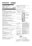
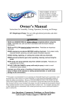
Vortex EF2201 Reference Manual VORTEX EF2201 REFERENCE MANUAL Introduction....................................................................................................2 Features and Benefits ............................................................................................. 3 Pre-Installation...............................................................................................4 EF2201 Front and Rear Panels.............................................................................. 5 Installation .....................................................................................................6 Mounting the EF2201 ............................................................................................. 6 Connecting the EF2201 to Other Equipment ......................................................... 7 Device IDs on the EF Bus....................................................................................... 8 Connecting Multiple EF2201 Devices.................................................................... 8 Factory Default Settings (Preset 0) ........................................................................ 9 Check Surrounding Equipment............................................................................... 11 Integrating the EF2201 Into Your System .....................................................12 Set up the Phone Interface...................................................................................... 12 The EF Bus ....................................................................................................13 Presets..................................................................................................................... 14 LCD Menu Structure .....................................................................................15 System Menu ........................................................................................................... 16 Phone Control......................................................................................................... 17 Inputs ...................................................................................................................... 18 Outputs.................................................................................................................... 19 Matrix Settings........................................................................................................ 19 Parametric EQ Menu.............................................................................................. 20 Presets..................................................................................................................... 21 Macros .................................................................................................................... 21 Troubleshooting .............................................................................................22 Residual Echo ......................................................................................................... 22 Can’t Receive Calls or Dial Out............................................................................. 22 Remote Control Problems....................................................................................... 23 Contacting Technical Support ................................................................................ 23 Technical Specifications ................................................................................25 Compliance ............................................................................................................. 25 EF2201 Block Diagram .................................................................................29 Connector Pinouts..........................................................................................30 Additional Notes ..................................................................................................... 32 Warranty Information ....................................................................................33 Definition of Terms .......................................................................................35 Index ..............................................................................................................37 Polycom, Inc., Copyright 2002 1 Technical Support: 1 800 Polycom INTRODUCTION INTRODUCTION Welcome Congratulations on your purchase of the Vortex EF2201! How to Use This Manual This is a reference manual for your EF2201. It is structured to provide the information you need quickly and conveniently. The following is an overview of each section: • • • • • • • • • • • About the EF2201 Introduction Pre-Installation includes information about the contents of the box, tools needed for installation and front and rear panel descriptions. Installation covers connections of inputs/outputs and calibration of inputs of the EF2201. Integrating the EF2201 Into Your System describes adjustments to take into consideration when integrating the EF2201 with surrounding equipment in your system. LCD Menu Structure describes an overview of the LCD menu structure and also gives a system overview of features and options available. Troubleshooting helps to debug problems with installation. Technical Specifications provides the technical specifications of the EF2201. EF2201 Block Diagram shows the inside of the EF2201. Connector Pinouts shows pinout diagrams for EF2201 input and output connectors. Warranty Information Definition of Terms explains terms used in this manual, as well as terms used in our technology of echo cancellation, noise cancellation, and audio conferencing. The Vortex EF2201 is the next generation of “digital hybrid” telephone interfaces. It features a complete digital interface to other Vortex products using the digital expansion bus. The EF2201 interfaces telephone audio to the Vortex family of products and allows up to 8 callers to be added to the same conference by using 8 EF2201s. Telephony signals are communicated with Vortex devices over the digital “P-bus” channel of the EF Bus without the need for an analog input and output. The EF2201 can be controlled via RS-232, Vortex Expansion bus, and via the front panel controls. The EF2201 has audible ring indications, user configurable entry and exit tones, and controllable levels of DTMF and dialtone signals. The EF2201 settings are configured using the Conference Composer software and can be stored as user presets within the EF2201. The EF2201 connects directly to an analog (PSTN) telephone line, connecting an outside caller to your meeting. In addition to providing crystal-clear telephone audio to all participants, the EF2201 significantly reduces background noise coming in on the telephone line to keep unwanted sounds from interfering with your conference. Product Registration Please take a moment to fill out and return your registration card. This information will help us to provide you with better customer support and will allow us to notify you with updated product features and software. VORTEX EF2201 Reference Manual 2 Technical Support: 1 800 Polycom INTRODUCTION FEATURES AND BENEFITS • • • • • • • • • • • • © Polycom, Inc. Telephone hybrid with noise cancellation for adding phone calls to conference Fully digital connection to the EF2200 series products with EF Bus -- does not require an analog input/output. Country specific telephone configuration settings Selectable auto-hang-up via loop drop and/or call progress tone detection 5-band parametric EQ on the phone input and output Automatic gain control on receive telephone audio path for consistent receive audio Compression/limiting on transmit telephone audio path User-set entry and exit tones give you the option to hear a pleasant tone when callers enter or leave the conference Conference up to 8 callers Built-in DTMF dialer allows users to dial without the use of a separate telephone Adjustable dial tone and DTMF levels RS-232, EF Bus, logic interface, and front panel LCD for control 3 VORTEX EF2201 Reference Manual PRE-INSTALLATION PRE-INSTALLATION What’s Included The Vortex EF2201 product package includes the following items: • • • • • • • • • Vortex EF2201 Reference Manual Vortex EF2201 External power supply Cat 5 cable for EF Bus Telephone cable Rack mount screws (4) Cable clamp and screw CD containing other manuals and Conference Composer software Product Registration Card Rackmount Screws (4) Vortex® EF2201 x x x x Cable Clamp and screw CD with control software and manuals Vortex® EF2201 User Guide 1-Cat 5 cable for EF Bus External Power Supply 1-Telephone cable Vortex EF2201 User Guide Figure 1. What’s Included with your Vortex EF2201. What’s Not Included Tools Needed for Installation The following equipment is not included with the EF2201 product package, but may be necessary to create a completely functional system: • • • • • • Acoustic Echo Canceller Microphones Loudspeakers Audio cables Video conferencing codec or other four-wire interface (optional) RS-232 remote control device (optional) • Screwdriver to mount the EF2201 in your rack. VORTEX EF2201 Reference Manual 4 Technical Support: 1 800 Polycom PRE-INSTALLATION EF2201 FRONT AND REAR PANELS 1 10 11 2 12 13 14 3 4 5 6 7 8 9 16 15 Figure 2. EF2201 Front and Rear Panels 1. 2. 3. 4. 5. 6. 7. 8. 9. 10. 11. 12. 13. 14. 15. 16. © Polycom, Inc. LCD DISPLAY. Displays menu instructions for configuration and operation of the EF2201. DOWN BUTTON. Scrolls backward through menu items at a particular level or decreases the value of a parameter. UP BUTTON. Scrolls forward through menu items at a particular level or increases the value of a parameter. ENTER. Enters the menu and allows you to select and change parameter values. ESC. Returns to the next highest level of menus. HOME. Returns to the top of the menu structure. LEVEL INDICATOR. Indicates the level of the selected channel or parameter. PHONE CONNECT. Takes the phone line on or off hook. If you have an analog handset connected to the PHONE jack on the back panel, pushing this button will disable the PHONE jack while enabling the LINE jack (see Item 17). PHONE CONNECT LED. Indicates when the phone line is on or off hook. INPUT PARALLEL PORT. Parallel logic input. OUTPUT PARALLEL PORT. Parallel logic output. EF BUS IN. Connects to EF BUS OUT of another Vortex device. EF BUS OUT. Connects to the EF BUS IN of another Vortex device. RS-232 SERIAL PORT. Connect this to an optional RS-232 remote control device, such as a touch panel or personal computer COM port. POWER SUPPLY INPUT. Connects to the external power supply provided with the EF2201. PHONE/LINE JACKS. Use the PHONE jack for connecting an analog handset to the system. Use the LINE jack for connecting to an analog telephone line. 5 VORTEX EF2201 Reference Manual INSTALLATION INSTALLATION This equipment is intended to only be installed by qualified service personnel. The equipment shall be connected to a socket-outlet that provides a protective earthing connection. North American Requirement CAUTION-To reduce the risk of fire, use only No. 26 AWG or larger telecommunication line cord. MOUNTING THE EF2201 The EF2201 can be mounted in a rack enclosure using four large screws (10-32x1/2”) included with the unit. One EF2201 fits in a single rack space. Recommendation For Easy Access While not required, leave a single rack space in between the EF2201 and other units in your rack. This gives you easier access to the back panel. Instructions for Securing Power Supply to Back of EF2201 • • • • • Locate the cable clamp on the back panel of the EF2201 above the power connector. Remove the screw and thread the power cord through the cable clamp. Attach the cable clamp to the back panel of the EF2201 and tighten the screw. Align the clamp so that the power cable does not interfere with the connectors on the EF2201 back panel. Plug in the power supply. We recommend that you also Ty-wrap the power supply to the rack. The purpose of securing the power supply to the back panel is so that if the power supply were to drop, it would pull where the cord is attached with the cable clamp and not pull the plug out of the EF2201. Caution! VORTEX EF2201 Reference Manual Do not use any other power supply other than the one provided with this unit. 6 Technical Support: 1 800 Polycom INSTALLATION CONNECTING THE EF2201 TO OTHER EQUIPMENT Typical EF2201 Connections The EF2201 will typically be connected to other equipment in a single room setup as shown below in Figure 3 and Figure 4. In 1 Out 1 In 2 Out 2 In 3 Out 3 In 4 Out 4 In 5 Out 5 In 6 Out 6 In 7 Out 7 In 8 POLYCOM Video Conferencing Unit Line In Line Out Out 8 Vortex® EF2280 In A Out A In B Out B In C Out C In D Out D EF Bus In PSTN Line EF Bus Out Phone Vortex® EF2201 EFBus In EFBus Out Figure 3. Block diagram of typical EF2201 connections: a single room using one EF2201. PSTN Vortex® EF2201 EF Bus Connection Vortex® EF2280 Room Amplifier Audio Amplifier ... 8 microphones POLYCOM Video Conferencing Unit TX RX Figure 4. Typical EF2201 connections. © Polycom, Inc. 7 VORTEX EF2201 Reference Manual INSTALLATION The following steps are typically used to set up the EF2201: • Connect the EF BUS IN to EF BUS OUT on a Vortex echo canceller. This connection will provide both audio and remote control information to and from the Vortex device. Connect the LINE RJ11 jack to an analog telephone line. Connect the PHONE RJ11 jack to an analog telephone set (optional). Connect the external power supply to the POWER SUPPLY INPUT jack of the EF2201. Set the country code on the EF2201. By default the phone interface will be disabled until you select a country code for the telephony interface. This can either be done with the front panel LCD menu, or the RS-232 interface. The country code only needs to be selected the first time or when the country of the installation is changed. • • • • NOTE The country code must be selected in order to begin using the EF2201. It only needs to be selected once at the beginning of use. DEVICE IDS ON THE EF BUS When considering which Device IDs can be used for which Vortex device, decide how many devices have the ability to transmit on the W, X, Y, and Z busses, and how many have the ability to transmit on the P Bus. The EF2201, for example, can only transmit on the P bus while the EF2241 can transmit on the W, X, Y, Z and P busses and the EF2280 can only transmit on the W, X, Y, and Z busses. Up to 8 devices can transmit on the W, X, Y, and Z busses. Similarly, up to 8 devices can transmit on the P bus. Note that the EF2241 counts as one of both types. All devices that can transmit on W, X, Y, and Z must have unique device IDs and all devices that can transmit on P must have unique device IDs. EF2201s and EF2241s must have unique device IDs since both can transmit on the P Bus. EF2280s and EF2241s must have unique device IDs since both can transmit on the W, X, Y, and Z busses. If the device IDs of linked Vortex devices that can transmit on the same busses are the same, the front panel LCD screen will display “EFBus Error: Dev. ID Conflict”. CONNECTING MULTIPLE EF2201 DEVICES Up to 8 EF2201 devices in combination can be linked together at one time (See Device IDs on the EF Bus above). Each unit in the chain must have a unique Device ID. Use the EF Bus to link multiple EF2201s together. The following steps should be followed to connect the EF Bus: 1. 2. 3. 4. Set a unique Device ID for each EF2201. The Device IDs range from 00 to 07. Power off all units. Connect the RS-232 remote control device to any EF2201 in the chain. Connect the provided Cat-5 cable between the EF BUS OUT of the first device, VORTEX EF2201 Reference Manual 8 Technical Support: 1 800 Polycom INSTALLATION and the EF BUS IN of the second device. Note 5. 6. Terminating the EF2201 The EF Bus must be connected so that the EF Bus In of one box is connected to the EF Bus Out of another. Connecting the EF Bus In to another EF Bus In (or Out to Out) will not work. Connect another Cat-5 cable between the EF BUS OUT of the second device and the EF BUS IN of the third device, and so on. Power on all units at the same time. The EF2201 is self-terminating so if you are connecting multiple EF2201s or connecting an EF2201 to an EF2241, the EF Bus does NOT need to be terminated. A terminator is not required for the EF2201 or for the versions of the EF2280 that has the input and output connectors stacked on top of each other as the terminator is builtin. However, if you are linking the EF2201 to legacy EF2280s (SKU 2200-82280xyz), terminate the EF Bus link on the EF2280. EF Bus Terminator Vortex EF2280 Cat-5 cable Vortex EF2201 No terminator is needed on EF2201 Figure 5. Terminate the EF Bus link on legacy EF2280’s when connecting an EF2201 to one or more EF2280s that has inline audio connectors. FACTORY DEFAULT SETTINGS (PRESET 0) The following is a list of the factory default settings of the EF2201. Since the equipment in your application may have different nominal levels, you can start with a FACTORY PRESET (Presets 0-15), change it to match your environment and then save it within the EF2201 as a USER PRESET (Presets 16-47). Once you’ve saved a USER © Polycom, Inc. 9 VORTEX EF2201 Reference Manual INSTALLATION PRESET, set the POWER ON PRESET to that USER PRESET (or whichever preset you want to come up after power up). The unit will need to be configured for your system. PROGRAM PARAMETERS FACTORY DEFAULT PRESET VALUE SYSTEM PARAMETERS Preset 0 Device ID 0 Baud Rate 9600 Flow Control Off PHONE CONTROL Auto Answer On Auto Hangup Call Progress Off Auto Hangup Loop Drop Off Dial Tone Gain 0 dB DTMF Gain 0 dB Ring Tone Enable On PHONE INPUT Automatic Gain Control (AGC) On AGC Maximum 12 dB AGC Minimum -6 dB AGC Rate 1 dB/s Phone Input Gain 0 dB Mute Off Noise Cancellation On Noise Cancellation Level 5 dB Line Echo Cancellation On Dynamics Processing On Filtering Off PHONE OUTPUT Mute Off Phone Output Gain 0 dB Dynamics Processing On Filtering Off VORTEX EF2201 Reference Manual 10 Technical Support: 1 800 Polycom INSTALLATION Presets and Multiple EF2201 Devices If you have multiple devices in your system, save settings to a user preset (Presets 1647) on each device. Saving a preset will only save the preset on that particular unit. Also, remember to set the POWER ON PRESET to the User Preset that you have saved your settings to otherwise the device will revert back to Preset 0 (factory default) if power is lost. CHECK SURROUNDING EQUIPMENT Check Levels to the Acoustic Echo Canceller © Polycom, Inc. If you are connecting the EF2201 to a Vortex device, the default level of 0 dB should give sufficient gain. 11 VORTEX EF2201 Reference Manual INTEGRATING THE EF2201 INTO YOUR SYSTEM INTEGRATING THE EF2201 INTO YOUR SYSTEM Operating the EF2201 The EF2201 can be operated in two ways: through the LCD menu on the front panel or through RS-232. For control via RS-232, please refer to the EF2201 Programming Guide, which includes programming tips as well as the EF2201 RS-232 commands. For operation using the PC control software, Conference Composer, please refer to the Conference Composer User Guide. Use Conference Composer software to easily configure the EF2201 with a PC, or refer to the Applications Guide for different configurations that are already programmed into factory presets. SET UP THE PHONE INTERFACE By default the phone interface will be disabled until you select a country code for the telephony interface. This can either be done with the front panel LCD menu, or the RS-232 interface. The country code only needs to be selected the first time or when the country of the installation is changed. Send audio from the phone to other linked devices by using the P bus output in the EF Bus. The linked devices can take the phone signal off the bus from the P Bus input. Receive audio from other linked devices by using the W, X, Y, and Z submatrix inputs (labelled WB0, WB1, etc. according to device IDs) on the EF Bus. For Multiple Devices To link multiple devices together, use the submatrix on the EF Bus to configure which signals to receive from other devices that have put their signals on the Bus. VORTEX EF2201 Reference Manual 12 Technical Support: 1 800 Polycom THE EF BUS THE EF BUS The EF Bus is a high speed, low delay digital bus that includes the W, X, Y, and Z audio busses, the P bus, as well as the echo canceller bus reference and remote control information (for other EF devices). On the EF Bus page in Conference Composer, the inputs coming in to each submatrix labelled WB0, WB1,... WB7 correspond with the device ID of the bus that is transmitting. The “B” denotes Bus. The submixes themselves, denoted as WM0, WM1, and WM2 are mixes that are input into the main matrix. The “M” denotes Mix. The EF Bus can link up to 8 devices that can transmit on W, X, Y, and Z outputs (such as the EF2280) and up to 8 devices that can transmit on the P output (such as the EF2201). Note that the EF2241 counts as one of both types. If the device can transmit on a particular bus, it cannot bring its own mix back into itself. For example, an EF2201 with ID 00 cannot add the input PB0 into PM0 or PM1 (see example in Figure 6 below). The W, X, Y, and Z busses include NOM information and can be used for sharing microphone inputs, or for sharing mono or stereo program information. See “Device IDs on the EF Bus” on page 8 for more information on how this affects Device IDs. The P Bus The P Bus is provided specifically to allow devices to share digital phone audio from the EF2201. The EF2201 and EF2241 can both transmit and receive signals on the P bus, while the EF2280 can only receive signals from the P bus. The W, X, Y and Z Busses Each EF2241 or EF2280 device in a system can create four output mixes (transmit on W, X, Y, and Z) and place them on the bus. Each EF2201, EF2241, and EF2280 device also can create three input (receive) mixes each from the W, X, Y, and Z busses of the other devices (for a total of 12 mixes). The mixes can have crosspoint gains on the signals from the other devices. See Figure 6 below. All 14 mixes (2 mixes on P, 3 mixes each on W, X, Y, and Z) become inputs to the main matrix of the EF2201 and can be mixed with other inputs to create outputs to the phone and P bus output. © Polycom, Inc. 13 VORTEX EF2201 Reference Manual THE EF BUS Figure 6. EF2201 P submatrix and W, X, Y, and Z submatrices. Note The EF Bus must be connected so that the EF BUS OUT of one Vortex device is connected to the EF BUS IN of another Vortex device. Connecting EF BUS IN to another EF BUS IN (or EF BUS OUT to EF BUS OUT) will not work. See“Connector Pinouts” on page 30 for pinout of Cat 5 cable. PRESETS After configuring your EF2201, save your settings to a User Preset (PRESETS 16-47). Also, set the POWER ON PRESET to the User Preset you have saved to. The POWER ON PRESET determines how the unit is configured upon power up. If you have multiple EF2201 devices in your system, save to a User Preset on each unit and set the POWER ON PRESET accordingly. VORTEX EF2201 Reference Manual 14 Technical Support: 1 800 Polycom LCD MENU STRUCTURE LCD MENU STRUCTURE LCD Menu Tree The EF2201 LCD menu structure is made up of seven menu trees: SYSTEM, PHONE CONTROL, INPUTS, OUTPUTS, PARAMETRIC EQ, PRESETS, and MACROS. Each menu tree is organized by levels and branches into multiple subcategories. The branches end with an adjustable parameter or value. EF2201 System Settings System Phone Control Input Settings Output Settings Matrix Parametric EQ Presets Macros Power On Preset Acknowledgeme nt Mode Auto Answer Input T Output T Main Matrix Input/Output EQ Restore Run Macro (0255) Auto Hangup Call Progress Phone Output Gain Channel Save Presets 16-47 Auto Hangup Loop Drop Line Echo Cancellation Automatic Gain Control (AGC) Band Delete Presets 16-47 Front Panel Password Country Select AGC Maximum Device ID Dial Tone Gain AGC Minimum DTMF Gain Phone Input Gain Error Messages Front Panel Lock Baud Rate Flow Control Meter Ring Tone Enable Gain Gate (In 1-4) Mute Output Mute Delay Enable SubMatrix Delay Gain Dynamics Processing Mute Mute Non-Volatile Memory Lcok Noise Cancellation Non-Volatile Mem Password Noise Cancellation Level Screen Saver LEC Suppression Last Restored Preset Dynamics Processing Filter Type Frequency Bandwidth Gain Slope Filter Enable Software Version Reboot Figure 7. LCD Menu Tree. DOWN UP ENTER ESC HOME Scrolls backward through menu items at particular level or decreases the value of a parameter Scrolls forward through menu items at particular level or increases the value of a parameter. Enters the menu and allows you to select and change parameter values. Returns to the top of the next highest level of menus Returns to the top of the menu structure. Table 1: Summary of button functions on the EF2201. The EF2201 has five menu buttons on the front panel for navigation in the menu tree. Press the HOME button from anywhere in the menu tree to return to the top of the menu. The ENTER button enters the menu and the ESC button returns to the next highest level of menus. To scroll back through menu items at a particular level, use the DOWN button. To scroll forward through menu items at a particular level, use the UP button. To adjust a parameter, first locate the parameter by scrolling to the appropriate menu (with combinations of the UP/DOWN and ENTER buttons). The display will show the parameter field and the parameter value. To change the parameter, the parameter must be flashing. To make the parameter flash (assuming the front panel is not locked) press ENTER. Once the parameter is flashing, use the UP and DOWN buttons to adjust the parameter value. The parameter is instantly updated while it is being adjusted — © Polycom, Inc. 15 VORTEX EF2201 Reference Manual LCD MENU STRUCTURE you should hear changes as the parameter is changing. RS-232 control strings are also sent via the RS-232 port so your remote control device is instantaneously updated as well. Press ENTER to select and store the parameter value or press ESC to cancel the selected value and return to the old value. Pressing HOME has the effect of pressing ESC then HOME, so the selected value will be cancelled and the menu will return to the top of the menu tree. Parameters that toggle or select among a list of options will wrap around when you reach the end, but parameters that adjust numeric values will not wrap around once the maximum or minimum value is reached. While adjusting a parameter, the UP/ DOWN button must be held down briefly before the repeat rate increases. SYSTEM MENU System Power On Preset Acknowledgeme nt Mode Error Messages Front Panel Lock Front Panel Password Device ID Baud Rate Flow Control The SYSTEM menu contains POWER ON PRESET, ACKNOWLEDGEMENT MODE, ERROR MESSAGES, FRONT PANEL LOCK, FRONT PANEL PASSWORD, DEVICE ID, BAUD RATE, FLOW CONTROL, METER, NON-VOLATILE MEMORY LOCK, NON-VOLATILE MEMORY PASSWORD, SCREEN SAVER, SOFTWARE VERSION, and REBOOT EF2201 configurations. Power On Preset Choose the EF2201 Preset for power up. Acknowledgement Mode This command controls whether or not status messages are sent. Error Messages Turns error messages On or Off. Front Panel Lock Locks or unlocks the front panel. When the front panel is locked, you can see the parameters but you cannot change them. The default passcode is aspi (case is important) Front Panel Passcode Once the device has been unlocked, the passcode may be changed. At the FRONT PANEL PASSCODE menu, press ENTER and then enter a passcode and press ENTER until you reach the end of the screen. Device ID Selects the Device ID of the unit. Baud Rate Selects baud rate of the RS-232. Meter Flow Control Selects flow control between Hardware, None, or Auto. Non-Volatile Memory Lcok Meter Selects which signal is displayed on the front panel LED meter. Non-Volatile Mem Password Screen Saver Last Restored Preset Software Version Reboot Figure 8. EF2201 System submenu Non-Volatile Memory Lock Controls the non-volatile lock feature. When the nonvolatile memory is locked, you can query the settings but will get an error if you try to change them. Non-Volatile Memory Password This feature sets or queries the non-volatile lock password. This password is used in conjunction with NON-VOLATILE MEMORY LOCK. The default password is aspi (case is important). Screen Saver Enables or disables the screen saver on the LCD panel. You can also set the idle time. Last Restored Preset Displays the last restored Preset. Software Version Queries the software version. Reboot EF2201 Causes the EF2201 to restart and boot up. VORTEX EF2201 Reference Manual 16 Technical Support: 1 800 Polycom LCD MENU STRUCTURE PHONE CONTROL Auto Answer Enables or disables auto answer. Auto Hangup Call Progress Enables or disables auto hangup based on call progress messages. Phone Control Auto Answer Auto Hangup Call Progress Auto Hangup Loop Drop Auto Hangup Loop Drop Enables or disables auto hangup cased on loop drop. Country Select Selects the country where you are using the unit. This must be set before you can use the unit and does not need to be set again unless you use the unit in a different country. Dial Tone Gain Adjusts the gain of the dial tone. DTMF Gain Adjusts the gain of the DTMF tones. Ring Tone Enable Enables or disables ring tones. Country Select Dial Tone Gain DTMF Gain Ring Tone Enable Figure 9. EF2201 Phone Control submenu © Polycom, Inc. 17 VORTEX EF2201 Reference Manual LCD MENU STRUCTURE INPUTS Input Settings Input T Line Echo Cancellation Automatic Gain Control (AGC) The input menu allows the user to adjust functions related to the input signals to the EF2201. This menu contains LINE ECHO CANCELLATION, AUTOMATIC GAIN CONTROL, AGC MAXIMUM, AGC MINIMUM, GAIN ADJUST, MUTE, NOISE CANCELLATION, NOISE CANCELLATION LEVEL, LEC SUPPRESSION, and DYNAMICS PROCESSING. The menu is organized around the Inputs (1-4) and (A-D), so that you first select an input and then select settings for that input. You can also choose to apply the settings to all Inputs, Inputs 1-4, or Inputs A-D. Line Echo Cancellation Enables or disables the echo cancellation on the phone line. Automatic Gain Control (Input T) This enables automatic gain control (AGC) on Input T. The default is On. AGC Maximum AGC Maximum (Input T) Sets the maximum gain value that the AGC can apply for Input T. The default value is +12 dB. AGC Minimum AGC Minimum (Input T) Sets the minimum gain value that the AGC can apply for Input T. The default value is -6 dB. Phone Input Gain Mute Phone Input Gain This parameter adjusts the gain level of the phone input (Input T). This is normally configured during the calibration process. The default setting is 0 dB. Mute Mutes/un mutes phone input. The default is not muted. Noise Cancellation Noise Cancellation (Input T) This allows you to enable or disable noise cancellation. Noise Cancellation Level Noise Cancellation Level (Input T) Selects the level of noise cancellation. This ranges from 0 to 15 dB. The default is 5 dB. LEC Suppression Dynamics Processing LEC Suppression Sets the amount of suppression used the line echo canceller (LEC). Dynamics Processing Enables or disables compression on Input T. Figure 10. EF2201 Inputs submenu VORTEX EF2201 Reference Manual 18 Technical Support: 1 800 Polycom LCD MENU STRUCTURE OUTPUTS The OUTPUT menu contains PHONE OUTPUT GAIN, MUTE, DELAY ENABLE, DELAY, and DYNAMICS PROCESSING. Output Settings Output T Phone Output Gain Mute Output Phone Output Gain Choose the gain applied to the outgoing phone signal. The default setting is 0 dBu. Though the EF2201 allows for positive output gain, you should always try to adjust input gains to a good level so that the output gain is 0 dB. If you find that you need a positive output gain from the EF2201, first check your input gain to make sure you are getting a good level (around 0 dB). Keep the output gain at around 0 dBu. Mute Output Use this to mute or unmute the phone output. Delay Enable Enables delay on Output T to the phone. Delay Sets the amount of delay on Output T. Delay Enable Dynamics Processing Enables or disables compression on Output T. Delay Dynamics Processing Figure 11. EF2201 Outputs submenu MATRIX SETTINGS The MATRIX menu includes gain and mute adjustments for the main matrix (Out T, In T, In PM0, PM1, WM0, WM1, etc.) and the submatrix (P submatrix, W, X, Y, and Z submatrices). Matrix Main Matrix Gain Mute SubMatrix Gain Mute Figure 12. EF2201 Matrix submenu © Polycom, Inc. 19 VORTEX EF2201 Reference Manual LCD MENU STRUCTURE PARAMETRIC EQ MENU Parametric EQ Input/Output EQ Channel Band Filter Type Frequency Bandwidth Gain Slope Filter Enable Figure 13. EF2201 Parametric EQ submenu The input equalizer is comprised of up to 5 bands of filtering. The whole group of filters for the channel can also be enabled/disabled without losing the settings for each band. For each band, you first select the type of filter from the following: Parametric/ Peaking, High Shelf, Low Shelf, Lowpass, Highpass, Linkwitz-Riley Low, or Linkwitz-Riley High. Parametric/Peaking. • Center Frequency: in Hz, between 20 Hz and 20,000 Hz in 1 Hz steps. • Bandwidth: in octaves, between 0.05 and 2 octaves in 0.05 octave steps. • Gain: in dB, between -20 and +20 in 1 dB steps. High Shelf. • • Center Frequency: in Hz, between 20 Hz and 20,000 Hz in 1 Hz steps. Bandwidth: in dB/octave, between 1 and 24 dB/octave, but is always less than or equal to 1.2 x Gain. • Gain: in dB between -20 and +20 in 1 dB steps. Low Shelf. • • Center Frequency: in Hz, between 20 Hz and 20,000 Hz in 1 Hz steps. Bandwidth: in dB/octave, between 1 and 24 dB/octave, but is always less than or equal to 1.2 x Gain. • Gain: in dB between -20 and +20 in 1 dB steps. Lowpass. • Cutoff Frequency: in Hz, between 20 Hz and 20,000 Hz in 1 Hz steps. Highpass. • Cutoff Frequency: in Hz, between 20 Hz and 20,000 Hz in 1 Hz steps. Linkwitz-Riley Low. •Frequency: in Hz, between 20 Hz and 20,000 Hz in 1 Hz steps • Slope between 24 dB/oct and 12 dB/oct Linkwitz-Riley High. •Frequency: in Hz, between 20 Hz and 20,000 Hz in 1 Hz steps • Slope between 24 dB/oct and 12 dB/oct Center frequency on Parametric/Peaking is the point with the most (or least) gain. Bandwidth is the width halfway up the peak (so if the peak is 10 dB, it is the width between the points where the gain is 5 dB). Center frequency on shelving filters is the frequency where it crosses the point halfway between 0 dB and the gain of the filter, halfway up the slope. VORTEX EF2201 Reference Manual 20 Technical Support: 1 800 Polycom LCD MENU STRUCTURE PRESETS Restore Restores the selected preset. Save Saves the selected user preset (Presets 16-47). Factory presets (Preset 0-15) cannot be overwritten. Presets Delete Deletes the selected user preset (Presets 16-47). Factory Presets (Presets 015) cannot be deleted. Restore Save Presets 16-47 Delete Presets 16-47 Figure 14. EF2201 Presets submenu MACROS Run Macro (0-255) Allows you to run macros from the front panel menu. Macros Run Macro (0-255) Figure 15. EF2201 Macros submenu © Polycom, Inc. 21 VORTEX EF2201 Reference Manual TROUBLESHOOTING TROUBLESHOOTING RESIDUAL ECHO If there is residual echo in the system, it may not be a problem with the EF2201. There are different types of echoes that come from different directions, and the EF2201 is only designed to remove one of them. The first step is to make sure the echo isn’t caused by something else. Then, the EF2201 can be adjusted to remove any residual echo coming from the hybrid. Identifying the Echo Source If the system has both audio and video conferencing, troubleshoot the system without the EF2201 at first. This will make sure the 4-wire Ax on both ends are working properly. If one side hears echo, there is a problem with the AEC on the other side. Troubleshoot the AEC according to the instructions for that device. Make a call to test the EF2201’s telephone interface. If the party on the phone hears echo, it is coming from the local or remote end. Disconnect one end at a time (by briefly unplugging the speaker or microphone) and see when the echo goes away. Troubleshoot the AEC on the side (local or remote) that was causing the echo. If residual echo is heard on the local end, try disconnecting the remote end. If the echo is still there, it is coming from the EF2201. Troubleshoot the EF2201 as described in the next section. If the echo goes away when the remote end is disconnected, troubleshoot the AEC on the remote end. If residual echo is heard on the remote end, disconnect the microphone(s) in the local room. If the echo is still there, it is coming from the EF2201. Troubleshoot the EF2201 as described below. If the echo goes away when the microphone is disconnected, the echo is coming from the local room. Troubleshoot the local AEC. Removing the Echo If the EF2201 is not removing hybrid echo, it may be due to a mismatch of levels coming into the EF2201. If levels are too far off, it may be difficult for the EF2201 to determine when to adapt its filter. Make sure the levels are in the correct range by watching the front panel LED meters during normal conversation. The signals should regularly be hitting the first yellow light, and occasionally flicker the second yellow light. Adjust the incoming signal levels if necessary. Also, make sure the Line Echo Cancellation feature is enabled. CAN’T RECEIVE CALLS OR DIAL OUT If you can’t receive calls or dial out, it could be because the telephone line is from a digital PBX system, or the remote control system is not properly connected. Test with an Analog Phone Try connecting a regular analog telephone to the EF2201’s line, and make a call. If the telephone will not work on that line, it is probably a digital PBX line from an office system. The EF2201 needs a standard analog line. You will need to get an analog phone line installed for the EF2201. VORTEX EF2201 Reference Manual 22 Technical Support: 1 800 Polycom TROUBLESHOOTING Try Dialing Manually If the analog telephone works on the line, try using it with the EF2201 to dial manually. Connect the LINE jack of the EF2201 to the telephone jack in the wall, and connect the handset to the PHONE jack. Try making a call. Fix the Remote Control If you can make calls by dialing with the analog handset, but not with the remote control device, that means there is a problem with the remote control. See the “Remote Control Problems” section below. REMOTE CONTROL PROBLEMS If the remote control device doesn’t seem to be affecting the EF2201, there are a few things you can check. Try sending commands that have a visible impact, like the PHONE command (which turns on the front panel PHONE light). Also, look for messages from the EF2201, like acknowledgement or error messages, if the remote control device can display them. Check Command Syntax Make sure the commands that are being sent to the EF2201 have the correct syntax. If only a couple of the commands aren’t being processed, there may be an error in the syntax of those commands. Remember, the commands are case sensitive. The EF2201 should return ERROR# messages if the commands are typed incorrectly, as long as error messages are enabled. Check Device ID Make sure the Device ID of the EF2201 matches the Device ID of the commands that are being sent. If they don’t match, the EF2201 will ignore all the commands. Try sending a command to all devices (*** instead of Device Type and Device ID). If this works but sending commands to a specific device doesn’t, the Device ID doesn’t match. Check RS-232 Make sure the RS-232 cable is connected securely to the EF2201 and the remote control device. The RS-232 cable should be connected straight through. Do not use a null modem. CONTACTING TECHNICAL SUPPORT If these troubleshooting guidelines don’t resolve the problem you are experiencing with the EF2201, please check our web site (http://www.polycom.com) for the most current technical support information. If you have further questions, please contact us at: Polycom Inc. 4750 Willow Road Pleasanton, CA 94588 Phone: 1 (800) Polycom (765-9266) Online Help www.polycom.com Choose eSupport © Polycom, Inc. 23 VORTEX EF2201 Reference Manual TROUBLESHOOTING eSupport is a source for product information, white papers, general questions, or you may check the status of an RMA. Before contacting us, please review the warranty and repair policy on page 33. VORTEX EF2201 Reference Manual 24 Technical Support: 1 800 Polycom TECHNICAL SPECIFICATIONS TECHNICAL SPECIFICATIONS MECHANICAL SPECIFICATIONS Dimensions 19” (483 mm) W x 9.6” (244 mm) L x 1.75” (45 mm) H (full rack unit) Weight 4 lb. (1.8 kg) dry 5.5 lb. (2.5 kg) shipping Connectors RS-232: DB9F EF Bus In/Out: RJ45 Phone In/Out: RJ11 Control/Status: DB25F POWER External Power Supply, provided Input Voltage 100 - 250 VAC; 50 - 60 Hz Power Consumption 15 W (typical) PERFORMANCE SPECIFICATIONS Operating Temperature 0 to 40 degrees Celsius Frequency Response 250 Hz to 3.6 kHz on telephony interface Line Echo Cancellation 40 dB, total 60 dB Convergence Rate 30 dB/second Cancellation Span 32 ms Noise Cancellation 0 dB to 15 dB, software selectable Control Inputs 24 Contact closure Status Outputs 20 status outputs, 5V, 20 mA each COMPLIANCE The Vortex EF2201 complies with the ITU G.165 Recommendation for LEC and FCC part 15. USA and Canada This device complies with part 15 of the FCC Rules. Operation is subject to the following two conditions: 1. 2. NOTE © Polycom, Inc. This device may not cause harmful interference, and This device must accept any interference received, including interference that may cause undesired operation. This equipment has been tested and found to comply with the limits for a Class A digital device, pursuant to part 15 of the FCC Rules. These limits are designed to provide reasonable protection against harmful interference when the equipment is operated in a commercial environment. This equipment generates, uses, and can radiate radio frequency energy and, if not installed and used in accordance with the instruction manual, may cause harmful interference to radio communications. Operation of this 25 VORTEX EF2201 Reference Manual TECHNICAL SPECIFICATIONS equipment in a residential area is likely to cause harmful interference in which case the user will be required to correct the interference at his own expense. In accordance with part 15 of the FCC rules, the user is cautioned that any changes or modifications not expressly approved by Polycom Inc. could void the user’s authority to operate the equipment. This Class [A] digital apparatus complies with Canadian ICES-003. Cet appareil numérique de la classe [A] est conforme à la norme NMB-003 du Canada. US Telco requirements This equipment complies with part 68 of the FCC Rules. Please refer to the labeling on equipment for the following information: • • • • • • Registration Number Ringer Equivalence Grantee's Name Model Number Serial Number and/or Date of Manufacture Country of Origin If requested this information must be provided to the telephone company Notes • • • • REN This registered equipment may not be used with party lines or coin lines. If trouble is experienced the customer shall disconnect the registered equipment from the telephone line to determine if the registered equipment is malfunctioning and that if the registered equipment is malfunctioning, the use of such equipment shall be discontinued until the problem has been corrected. If, in the unlikely event that this equipment causes harm to the network, the telephone company will notify you in advance that temporary discontinuance of service may be required. But if advance notice isn't practical, the telephone company will notify you as soon as possible. Also, you will be advised of your right to file a complaint with the FCC if you believe it necessary. The telephone company may make changes to its facilities, equipment, operations or procedures that could affect the operation of the equipment. If this happens the telephone company will provide advance notice so you can make the necessary modifications to maintain uninterrupted service. The REN is used to determine the quantity of devices that may be connected to the telephone line. Excessive REN's on the telephone line may result in the devices not ringing in response to an incoming call. Typically the sum of REN's should not exceed five (5.0). To be certain of the number of devices that may be connected to a line (as determined by the total REN's) contact the local telephone company. VORTEX EF2201 Reference Manual 26 Technical Support: 1 800 Polycom TECHNICAL SPECIFICATIONS Automatic Dialing WHEN PROGRAMMING EMERGENCY NUMBERS AND/OR MAKING TEST CALLS TO EMERGENCY NUMBERS 1. 2. Remain on the line and briefly explain to the dispatcher the reason for the call. Perform such activities in the off-peak hours, such as early morning or late evening. Telco Connector A FCC compliant telephone cord and modular plug is provided with this equipment. This equipment is designed to be connected to the telephone network or premises wiring using a compatible modular jack that is Part 68 complaint. See the rest of these installation instructions for details. Canadian Telco Requirements This product meets the applicable Industry Canada technical specifications Before installing this equipment, users should ensure that it is permissible to be connected to the facilities of the local telecommunications company. The equipment must also be installed using an acceptable method of connection. The customer should be aware that compliance with the above conditions may not prevent degradation of service in some situations. Repairs to certified equipment should be coordinated by a representative designated by the supplier. Any repairs or alterations made by the user to this equipment, or equipment malfunctions, may give the telecommunications company cause to request the user to disconnect the equipment. The Ringer Equivalence Number (REN) assigned to each relevant terminal device provides an indication of the maximum number of terminals allowed to be connected to a telephone interface. The termination on an interface may consist of any combination of devices subject only to the requirement that the sum of the Ringer Equivalence Numbers of all the devices does not exceed 5.'' The REN of this equipment is either marked on the unit or included in the new style USA (FCC registration number). In the case that the REN is included in the FCC number the user should use the flowing key to determine the value: The FCC number is formatted as US: AAAEQ##TXXX. ## is the Ringer Equivalence Number without a decimal point (e.g. REN of 1.0 = 10, REN of 0.3 = 03). In the case of a “Z” ringer, ZZ shall appear. In the case of approved equipment without a network interface and equipment not connecting to circuits with analog ringing supplied then “NA” shall appear. Australia Mains powered POT’s Voice Telephony without Emergency 000 dialing Warning This equipment will be inoperable when mains power fails © Polycom, Inc. 27 VORTEX EF2201 Reference Manual TECHNICAL SPECIFICATIONS Japan (VCCI) Class A ITE Korea Class A ㌂㣿㧦㞞⌊ⶎ(㩲 5 㫆㩲 1 䟃㩲 2 䢎ὖ⩾) A ₆₆ (㠛ⶊ㣿 ㏷䐋㔶₆₆) 㧊 ₆₆⓪ 㠛ⶊ㣿(A )㦒⪲ 㩚㧦䕢㩗䞿❇⪳㦚 䞲 ₆₆㧊㡺┞ 䕦ⰺ㧦 ⡦⓪ ㌂㣿㧦⓪ 㧊 㩦㦚 㭒㦮䞮㔲₆ ⧒Ⳇ, Ṗ㩫㣎㦮 㰖㡃㠦㍲ ㌂㣿䞮⓪ ộ㦚 ⳿㩗㦒⪲ 䞿┞┺. Rest of World EMC CLASS A ITE WARNING This is a Class A product. In a domestic environment this product may cause radio interference in which case the user may be required to take adequate measures. Installation Instructions* Installation must be performed in accordance with all relevant national wiring rules. L’Installation doit être exécutée conformément à tous les règlements nationaux applicable au filage électrique. Plug acts as Disconnect Device* The socket outlet to which this apparatus is connected must be installed near the equipment and must always be readily accessible VORTEX EF2201 Reference Manual 28 Technical Support: 1 800 Polycom EF Bus © Polycom, Inc. TLP 29 On Off AGC Parameters Noise Canceller Tone Gen. Copyright (c) 2002, Polycom. All Rights Reserved Confidential Information. Do Not Disclose Parameters PEQ TLP (Telephone Line Processing) Matrixing PEQ Parameters Call Prog Detect LEC On Off Mute A/D D/A Phone Telephone Line Control/Status RS-232 EF2201 BLOCK DIAGRAM EF2201 BLOCK DIAGRAM Figure 16. Inside the EF2201 VORTEX EF2201 Reference Manual CONNECTOR PINOUTS CONNECTOR PINOUTS EF Bus EF BUS IN 8 1 1 8 The EF Bus uses RJ45 connectors. These should be used with category five twisted-pair cable. The total distance of the EF Bus should be less than 4.5 m. The EF Bus must be connected so that the EF Bus In of one box is connected to the EF Bus Out of another. Connecting the EF Bus In to another EF Bus In (or Out to Out) will not work. EF BUS OUT Cat-5 Plug Pinout 8 1 - White/Orange 2 - Orange 3 - White/Green 4 - Blue 5 - White/Blue 6 - Green 7 - White/Brown 8 - Brown 1 Cat 5 Plug (Front View) RJ11 Plug Pinout 3 - Ring 4 - Tip Note: Other pins are not connected. The DAA is not affected by Tip and Ring wiring reversal. RS-232 Port (9600, 19200, 38400, 8-N-1) The RS-232 port is wired as DCE. It accepts a male DB-9 connector. Only pins 2, 3, and 5 are required by the EF2201 but pins 7 and 8 are supported. Connect pins straight through (do not use null modem). 1 DCD; 2 TXD; 3 RXD 4 DSR; 5 ground; 6 DTR; 7 CTS; 8 RTS; 9 No connection REMOTE CONTROL 5 1 9 6 RS-232 Baud rate is selectable at 9600, 19200, or 38400. VORTEX EF2201 Reference Manual 30 Technical Support: 1 800 Polycom CONNECTOR PINOUTS Input/Output Remote Control Port INPUT 13 Logic Input: Pins 1-24 are inputs 1-24, respectively. Pin 25 is ground. 1 25 14 REMOTE CONTROL Logic Output: Pins 1-20 are outputs 1-20, respectively. Pins 21-25 are ground. Each ground pin should be used with only 4 outputs. For example, outputs 1-4 could be connected to LEDs, which are connected to ground pin 1. OUTPUT LEDs can be used without series resistors (we have provided series resistors in the circuitry). For best results, LEDs with Vf=2.0 V and If=20 mA should be used. Larger values may be used, but may result in dimmer LEDs. An LED with Vf less than 1.4 V should not be used without additional series resistance. Power Supply Input 5, 15 VDC 3 The power supply input accepts a 5-pin DIN male connector. Only use the power supply provided by Polycom. Use of other power supplies will void the warranty. 1 5 2 4 1 Ground; 2 Ground; 3 +5Vdc @ 3 A; 4 -15VDC @ 0.3 A; 5 +15Vdc @ 1.2 A © Polycom, Inc. 31 VORTEX EF2201 Reference Manual CONNECTOR PINOUTS ADDITIONAL NOTES Caution! Caution! Caution! Caution! Caution! Failure to use all four screws to attach the EF2201 to the rack may result in uneven loading and cause a safety hazard. Ensure that the power supply is securely located such that it cannot become dislodged and fall. Such a fall could cause personal injury or equipment failure. When mounting a EF2201 in a rack, consideration should be given to airflow and operating ambient temperatures inside the rack. To ensure safe operation of the EF2201, ambient operating temperatures inside the rack should not exceed 40 degrees Celsius. Allow 2 inches (51mm) of open space in front of the EF2201, 2 inches (51mm) on either side, and 4 inches (102 mm) behind the unit for proper ventilation. Equipment should not be installed in the rack in such a way as to interfere with the ventilation of the EF2201. Consideration should be given to the connection of the equipment to the supply circuit and the effect that overloading of circuits could have an overcurrent protection and supply wiring. Appropriate consideration of equipment nameplate ratings should be used when addressing this concern. Reliable earthing of rack-mounted equipment should be maintained. Particular attention should be given to supply connections other than direct connection to the Branch (use of power strips). VORTEX EF2201 Reference Manual 32 Technical Support: 1 800 Polycom WARRANTY INFORMATION WARRANTY INFORMATION What is covered Any defect in materials or workmanship. For how long Two years. What we will do If your Vortex EF2201 product is defective and returned within two years of the date of purchase, we will repair or, at our option, replace it at no charge to you. If we repair your Vortex product, we may use new or reconditioned replacement parts. If we choose to replace your Vortex product, we may replace it with a new or reconditioned one of the same or similar design. The repair or replacement is warranted for either (a) 90 days or (b) the remainder of the original two-year warranty period, whichever is longer. Limitations Polycom shall not be responsible for special, incidental, indirect, or consequential damages resulting from any breach of warranty, or under any other legal theory, including but not limited to loss of profits, downtime, goodwill, damage to or replacement of equipment and property, and any cost of recovering, reprogramming, or reproducing any program or data stored in or used with Vortex products. Some states do not allow limitations on how long an implied warranty lasts, or the exclusion of incidental or consequential damages, so the above exclusions or limitations may not apply to you. What we ask you to do To obtain warranty service for your Vortex product, call your local support office and we will issue a Return Material Authorization number (RMA#). Use the original packaging materials to return the product. Ship the product to the address supplied to you. Repair or replacement of your Vortex product is your exclusive remedy. What this warranty does not cover This warranty does not cover defects resulting from accidents, damage while in transit to our service location, alterations, unauthorized repair, failure to follow instructions, misuse, fire, flood, lightning, acts of God, or use in those countries where such use violates Part 779 of the Export Administration Regulations of the United States Department of Commerce. If your Vortex product is not covered by our warranty, call your local support office for advice about whether we will repair your Vortex product and for other repair information, including charges. Polycom, at its sole discretion, may replace rather than repair your Vortex product with a new or reconditioned one of the same or similar design. The repair or replacement is warranted for 90 days. The limited warranties and remedies set forth above are exclusive and in lieu of all other warranties, whether oral or written, express or implied. Polycom specifically © Polycom, Inc. 33 VORTEX EF2201 Reference Manual WARRANTY INFORMATION disclaims any and all implied warranties, including, without limitation, the warranties of merchantability and fitness for a particular purpose. No User Serviceable Parts This product contains no user serviceable parts. Please contact Polycom Installed Voice Business Group for repairs. Attempts to repair this product by an unauthorized technician will void your warranty. State Law Rights This limited warranty gives you specific legal rights, and you any have other rights that may vary from state to state. VORTEX EF2201 Reference Manual 34 Technical Support: 1 800 Polycom DEFINITION OF TERMS DEFINITION OF TERMS Acoustic Echo Acoustic echo occurs in a conferencing or distance learning system when the remote speech played in the loudspeakers is picked up by microphones in the room and is transmitted back to the remote end. This transmitted signal is a delayed version of the original, which causes the echo. Acoustic Gain Acoustic gain is a term used in conjunction with sound reinforcement. It refers to how much louder the audio is with sound reinforcement compared to without sound reinforcement. Ambient Level The ambient level, also referred to as noise floor, is the background noise heard in a room when no one on the near or remote end is talking. Automatic Gain Control (AGC) Automatic gain control increases or decreases the gain on an audio signal to an acceptable value. Automatic Microphone Mixer A microphone mixer that turns microphone channels on and off based on the signal level going into the microphone. Convergence Rate Convergence rate refers to the amount of echo a line or acoustic echo canceller can cancel per unit time, typically expressed in dB/sec. Better echo cancellers have a higher (faster) convergence rate. This term is typically used to quantify the time it takes to completely remove the echo from a conferencing system. Echo occurs due to a complete change of the acoustic environment such as the beginning of a phone call in a conference, a change of microphone-speaker placement, or speaker volume adjustment. Crosspoint Mix Minus Bus A mix minus bus allows each device to create a mix of signals without its own. The submix (W, X, Y, Z, or P) inputs to the main matrix are mix minuses. Echo Canceller An echo canceller estimates the echo in an audio signal by using a reference and preforms processing to eliminate the echo from the signal. EF Bus The EF Bus is a digital bus that includes the W, X, Y, and Z audio busses as well as the echo canceller reference and remote control information. It can be used to link multiple Vortex devices. © Polycom, Inc. 35 VORTEX EF2201 Reference Manual DEFINITION OF TERMS Equalization Equalization is the process of adjusting frequency characteristics of an audio signal. Line Echo Line echo is caused by reflections of the audio signal from the telephone hybrid. The EF2201 is an example of a device that includes a line echo canceller. Macros An arbitrary set of commands that can be replayed. Matrix Mixer A matrix mixer allows you to choose which inputs are included in each output. Some matrix mixers allow you to assign crosspoint gains to the inputs. Noise Cancellation Noise cancellation is a digital signal process that removes noise from an audio signal corrupted by real-world interferences such as HVAC, office noise, crowd noise, or road noise. Generally, there are two parts of a noise cancellation algorithm: a method to detect the noise and a method to remove the noise. The Polycom noise cancellation algorithm (patent pending) is capable of removing 10 dB or higher of noise with no degradation at all to the resulting speech signal. This method does not attenuate speech, and removes noise during both speech and idle periods. NOM NOM refers to the number of open microphones in a system. NOM Attenuation NOM attenuation is the gain applied to the overall system gain to the microphone signals to compensate for how many microphones are open. The amount of attenuation is calculated by 10*log10(NOM). NOM Bus A NOM bus carries signal information as well as NOM information (i.e., the number of open microphones in the system, NOM). Presets Presets correspond to configuration parameters that have been previously saved to EEPROM. Room Gain The room gain of a conferencing system refers to the relative levels of the signal sent to the line output to your amplifier (before any amplification) and the level of this signal that is reflected at the microphone input (after microphone amplification). If the electrical level of the reflected signal picked up by the microphone is the same as the level of the electrical signal sent from the AEC to the line output to your amplifier, the room gain of this microphone channel is said to be 0 dB. If the reflected signal picked up by the microphone is higher than the level of the signal sent to the line output to your amplifier, that microphone channel has positive room gain. The more positive the room gain, the harder the AEC must work to determine which signal is an echo and which is a local speech signal. VORTEX EF2201 Reference Manual 36 Technical Support: 1 800 Polycom INDEX INDEX A C D E F G L M N Acoustic Echo Cancellation, AEC 35 Automatic Gain Control (AGC) 18, 35 Automixer, Automatic Microphone Mixer 35 Compliance 25 Conference Composer 4, 12 Device ID 8, 10 Digital Bus 13, 35 EF Bus 4, 5, 8, 9, 12, 13, 14, 25, 30, 35 Equalization 36 Factory Default Settings, Preset 0 9 Front Panel Lock 16 Ground, Ground, Ground, Ground, Logic Input 31 Logic Output 31 Power Supply 31 RS-232 30 LCD Menu 5, 12, 15 Line Echo Cancellation, LEC 25 Line Echo Canceller, LEC 36 Logic Input 5, 31 Logic Output 5, 31 Mix Minus 35 Noise Cancellation 18, 25, 36 NOM 13, 36 NOM Attenuation 36 NOM Bus 36 Non-volatile Memory Lock 16 © Polycom, Inc. 37 VORTEX EF2201 Reference Manual INDEX O P R S T Outputs 19 P Bus 8, 12, 13 Parallel Remote Control 5 Phone 5, 8, 12, 13, 19, 25, 36 Power On Preset 11, 14 Presets 36 Reference, AEC 13, 35 Room Gain 36 RS-232, Serial Remote Control 4, 5, 12, 13, 16, 18, 25, 30 Submatrix 14 Technical Support 23 Terminating the EF Bus, Terminators 9 VORTEX EF2201 Reference Manual 38 Technical Support: 1 800 Polycom INDEX © Polycom, Inc. 39 VORTEX EF2201 Reference Manual Polycom, Inc. 4750 Will Road Pleasanton, CA 94588-2708 USA www.polycom.com Polycom®, Vortex®, and the Polycom logo are registered trademarks of Polycom, Inc. in the United States and various countries. Copyright © 2002 Polycom, Inc. All rights reserved. P/N 1725-80101-001 Rev C