1
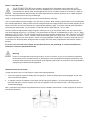
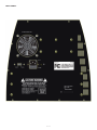
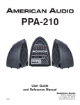
PPA-300
PORTABLE SOUND SYSTEM
OPERATING INSTRUCTIONS
IMPORTANT SAFETY INSTRUCTIONS
The PPA-300 should not be exposed to liquid, nor should items filled with liquid be placed on the device. The
MAIN plug disconnects device.
Warning: The disconnected device could still have electricity or heat circulating even after being disconnected.
Warning: The user should not place this device in a confined area during operation so that the main switch
cannot be accessed.
1. Read these instructions before operating this
device.
2. Keep these instructions for future reference.
3. Heed all warnings to ensure safe operation.
CAUTION
RISK OF ELECTRIC SHOCK
DO NOT OPEN
4. Follow all instructions provided in this document.
5. Do not use this apparatus near water or in locations where condensation may occur.
6. Clean only with dry cloth. Do not use aerosol or
liquid cleaners. Unplug this apparatus before
cleaning.
7. Do not block any of the ventilation openings.
Operate in accordance with the manufacturer’s
instructions.
8. Do not operate near any heat sources such as
radiators, heat registers, stoves, or other apparatuses (including amplifiers) that produce heat.
9. Operate using the polarized or grounding-type
plug. A polarized plug has two blades with one
wider than the other. A grounding plug has two
blades and a third grounding prong. The wide
blade or the third prong is provided for your safety.
If the provided plug does not fit into your outlet,
consult an electrician for replacement of the obsolete outlet.
10. Protect the power cord from being walked on or
pinched particularly near the plug and the point
where they exit from the PPA-300.
11. Only use attachments and/or accessories which
are compatible with the unit.
12. Use only with a cart, stand, tripod, bracket, or table
that is compatible with the unit. When a cart is
used, use caution when moving the cart/apparatus
combination to avoid injury from tipover.
13. Unplug the PPA-300 during lightning
storms or when unused for long periods of time.
14. Refer all servicing to qualified service personnel. Servicing is required
when the apparatus has been damaged in any
way, such as power-supply cord or plug is damaged, or liquid has been spilled into the unit. The
PPA-300 may not function properly if exposed to
rain or moisture, or if it has been dropped.
CAUTION: TO REDUCE THE RISK OF ELECTRIC SHOCK,
DO NOT REMOVE COVER (OR BACK)
NO USER SERVICEABLE PARTS INSIDE
REFER SERVICING TO QUALIFIED PERSONNEL
The lightning flash with arrowhead
symbol, within an equilateral triangle, is
intended to alert the user to the presence
of uninsulated “dangerous voltage” within
the product’s enclosure that may be of
sufficient magnitude to constitute a risk of
electric shock to persons.
The exclamation point within an equilateral
triangle is intended to alert the user to
the presence of important operating and
maintenance (servicing) instructions in the
literature accompanying the device.
WARNING: To reduce the risk of fire or electric
shock, do not expose the PPA-300 to rain or
moisture.
CAUTION: Use of controls or adjustments to device
other than those for which the device is designed
may result in hazardous radiation exposure.
PPA-300
PORTABLE SOUND SYSTEM
INTRODUCTION
• 8-Channel powered mixer.
• Four XLR MIC inputs.
• Two TRS stereo Channels with RCA 3.5mm Stereo inputs.
• Channels with 3-bend EQ, EFX Sound, Pan, Level.
• USB PORT CONNECT TO FLASH DRIVE, MP3 PLAYER.
• Effects send on every channel with stereo return.
• Internal Digital delay effects processor with 16 selections end foot switch jack, including echo,
delay end vocal enhancement.
• Effect parameter adjustment allows you to customize each effect selection.
• 7-band system equalizer with switch.
• Two five-segment LED meters.
• Performance Indicators: Signal, Clip, Power and Protect.
• 300W (150W 8ohms per channel) stereo amplifier with built-in dynamic distortion processor,
turn-on/turn-off.
• Speaker system with 1” compression driver and 10” woofer.
• Storage compartment for cables and accessories.
• Two speaker cables.
This symbol warns the user of dangerous voltage levels localized within the enclosure.
This symbol advises the user to read all accompanying literature for safe operation of the unit.
Congratulations on your purchase of the AVTRONICS PPA-300 high performance portable audio system. Your PPA300 offers great sound. Carry your PPA-300 as a large sized suit case. Flip open the speaker latches, and you’ll
discover two full-range speaker cabinets, a powered mixer, and cables. Use your PPA-300, with quick and easy
setup and simple operation, to cover sound needs for large audiences.
The PPA-300’s control panel features four mono mic/line inputs and two stereo channels (six channels total).
The stereo input channels can be used for either mono or stereo operation allowing superb flexibility of input use.
Moreover, the tailored speakers in each speaker enclosure deliver clear, full range sound with exceptional audience
coverage and remarkable feedback rejection. The self-powered mixer provides a total of 300 watts of high quality
stereo sound. Experiment with the tone controls, digital reverb and speaker placement to discover the PPA-300’s
incredible power and versatility.
IMPORTANT SAFEGUARDS:
- WARNING: TO PREVENT DAMAGE, FIRE OR SHOCK HAZARD, DO NOT EXPOSE THIS
UNIT TO RAIN OR MOISTURE.
- NO USER SERVICEABLE PARTS INSIDE ENCLOSURE, REFER SERVICING TO QUALIFIED
AND AUTHORIZED PERSONNEL .
- THIS UNIT MUST BE GROUNDED.
–1–
SAFETY PRECAUTIONS
The AVTRONICS PPA-300 sound system is supplied with a detachable power cable with an lEG
female connector and a male AC connector. Depending on the territory in which the PPA-300 system
is purchased, the power cable will be supplied with one of a number of male AC connectors in order to
accommodate the different safety and code requirements of specific countries. All AC cables supplied
with PPA-300 products are three pin grounded type.
Under no circumstances should the ground pin be disconnected or removed.
Your PPA-300 System converts voltage 115V and 230V by switch. When travelling abroad with the PPA-300 system,
as a standard precaution, always check the local voltage and set the voltage selector switch located adjacent to the
socket on the rear of the mixer amplifier to the appropriate operating range. This check must be performed before
connecting the power cable. The AVTRONICS PPA-300 has two range settings: 115V or 230V.
Failure to select the appropriate voltage range will cause the unit to go into protect mode, void any warranty and
may cause damage to the unit. For example, The United States of America is standardized at 120 V / 60 Hz, Japan
operates on 100 V / 50 Hz. For both of these countries the range selector must be set to 115V. Countries in the EEC
have standardized at 230 V / 50 Hz, however, there are different types of AC plugs used. For all the EEC countries
the selector should be in the 230V position. When using plug adapters or operating in a territory other than the one
in which the unit was purchased, take great care to comply with local safety requirements and electrical codes of
practice.
If you are not sure of the local voltage, wiring codes & colors, AC grounding, or correct procedures for
connection, consult a qualified technician.
Warning
Under no circumstances should the ground pin on the PPA-300 or on any of your electrical equipment
be removed (cut off or disconnected). By following the correct procedures and safety precautions, risks
of severe shock hazard can be minimized. Avoid operating the system in conjunction with ungrounded or
improperly grounded electrical equipment.
TRANSPORTATION LATCHES
To open and close your PPA-300 system, simply follow these guidelines:
I.
Place your finger tip under the safety latch and gently lift. When the safety latch has disengaged, lift the main
latch to remove the speaker.
2. To replace, position the speaker on the tower foot and bring the speaker in to close the engagement with
the tower and latch. Position the latch hook over the speaker notch and close the latch. The safety latch will
automatically engage.
Note: These parts are precision engineered and no force is needed to secure them. Careful alignment of parts will
ensure easy operation.
–2–
FRONT PANEL
–3–
CONTROL FUNCTIONS
1)
HIGH - Adjusts the relative level of the high frequency content. Rotating the knob counterclockwise decreases
the high or low frequency response. Likewise, rotating the knob clockwise increases the high or low response.
2)
MID -Adjusts the relative level of the mid frequency content. Rotating the knob counterclockwise decreases
the high or mid frequency response. Likewise, rotating the knob clockwise increases the high or mid frequency
response. When the EQ controls are set at their middle position, the channel frequency response is “flat” with
no frequencies increased or decreased.
3)
LOW - Adjusts the relative level of the low frequency content of the channel 1. Rotating the knob clockwise
increases the bass or low frequency response. Likewise, rotating the knob counterclockwise decreases the
bass or low frequency response. Likewise, rotating the knob counterclockwise decreases the bass or low
frequency response.
4)
EFF / AUX - Adjusts the amount of signal sent to the reverb processor, and to the EFF / AUX output jack.
Reverb can be used to enhance the sound quality of any performance where appropriate and desired. In the
full left position there is no level sent to the reverb processor or EFF /AUX jack. Care should be taken to set the
reverb return master control to a middle position or above, before adjusting levels from the individual channel.
When the reverb/auxiliary mix is set, overall levels of reverb can be adjusted at the master control. Reverb or
effects can enhance a musical performance or presentation. However, too much reverb can make the same
performance or presentation unintelligible or “muffled”. Keep your audience in mind when setting reverb levels.
5)
PAN - The Pan control features a notched position indicator and adjusts the perceived “position” of the mono
signal from the input within the stereo field created by the two speaker cabinets. Full left or right rotation of this
control sends the signal to the that channel only, with no signal sent to the other. The center position sends the
same amount of signal to both speakers.
6)
LEVEL - Adjusts the volume level of the individual channel. Rotating the knob clockwise increases the
respective channel’s contribution to the “Main Out” mix, while rotating it counterclockwise decreases the
volume. Adjust this control after the PPA-300’s master output level volume has been set.
7)
BAL - The balance control features a notched position indicator and adjusts the perceived “position” of the
mono signal from the input within the stereo field created by the two speakers. Full left of right rotation of this
control sends the signal to the that channel only, with no signal sent to the other. The center position sends the
same amount of signal to both speakers.
DIGITAL EFFECTS
8)
Digital delay display - 00(12ms) to 15(197ms)
9)
Digital delay display adjustment
1O) Digital echo adjustment
11) MIX TO MAIN - Digital delay effects output level adjustment
12) AUX Level - EFF / AUX Return input level adjustment
MASTER CONTROL
14, 15, 31 & 35) These LED’s monitor the output signal levels of both the main or output signals. The red LED is
illuminated when the internal limiter is engaged to prevent the signal from being clipped. (Clipping results in
overdrive distortion and should be avoided.) If the Limiter LED is flashing continuously or remains on constantly
during use, reduce the output signal levels until they flash only on strong signal peaks.
16 & 17) MASTER VOLUME LEVEL CONTROLS - The left and right master volume controls adjust the output
volume of the PPA-300. The master controls feature notched position indicators. For the majority of applications
the PPA-300 system has been balanced to operate with these controls at their notched 12 o’clock positions.
In situations where more volume is required the master controls can provide an additional 6 dB of gain
when turned to the right of the center position. Set the system up in the normal manner and adjust levels
as necessary. Raise the master volume controls beyond their 13 o’clock positions only after increasing the
individual channel level controls. PPA-300’s internal amplifiers have on-board processing designed to optimize
the system’s performance when used with the custom designed PPA-300 speakers.
–4–
18) STEREO / DUAL SELECTOR SWITCH - Allows the PPA-300’s power amps to be configured as stereo or “dual
- mode”. In the Stereo mode, the system operates as a traditional stereo power mixer / amplifier. In the dual
mode, the channel level controls set the level for the Main mix (LEFT master volume control). The Rev / Aux
controls set the individual channel levels for the Monitor (RIGHT master volume control). When the Dual mode
position is selected with the switch, the Pan and Balance controls become inoperative (you have selected a
mono setting for the output). Additionally, the internal reverb is only sent to the MAIN speaker output. Reverb
is not available to the MONITOR speaker output. The reverb level sends for the MAIN mix are also controlled
from the channel DSP / AUX channel controls. The overall reverb level to the MAIN mix is controlled by the
Reverb Master Control.
19) EQ CONTROL - Adjusts the EQ sliders. The 7 band EQ is connected into the system, when the EQ button is in
the off position the audio signal will go directly to the system without EQ.
20) SYSTEM EQUALIZER - Adjust the amount of frequency increase or decrease in the channel. The left
and right channels are adjusted simultaneously at same time and same pace. Set frequencies are at
60Hz,160Hz,400Hz,1KHz, 2.5KHz,6KHz, 16KHz, adjusting range within +/-12dB; When the sliding stick is at
the middle position, the frequency response is “flat” with no frequencies increased or decreased; Sliding the
stick up increases the frequency response of that band, sliding the stick down decreases that band’s frequency
response. To set the EQ, start with this control from the middle (“0dB” marked) position. Simply slide the sticks
until your desired sounds are there.
MIC/LINE STEREO INPUTS
22) MIC INPUT JACK - Plug your microphone in here. This is a three pin XLR balanced female input.
21) LINE INPUT JACK - Plug your instrument in here. This 1/4” balanced input jack is suited for use with items
having a line level output such as high impedance microphones, keyboards, drum machines, outboard effects,
etc. It accepts both balanced and unbalanced cables.
23 & 32) STEREO INPUTS - Stereo phono (7/50”TRS) input jacks and 1/4” TRS jacks (wired for Tip=Left,
Ring=Right and Sleeve= Ground, the standard format of commercially available cables) designed for use with
a tape player, DVD player, or any other stereo source. Use these jacks for connecting the output of a computer
sound card or other similar device to your PPA-300. Adapters that convert an 1/8” male plug to RCA male
phono plugs are readily available at electronics stores.
Note: These connectors are set at a constant “line level”.
24 & 30) STEREO INPUTS - Stereo phono (RCA) input jacks and 1/4” TRS jacks (wired for Tip=Left, Ring=Right
and Sleeve= Ground, the standard format of commercially available cables) designed for use with a tape
player, DVD player, or any other stereo source. Use these jacks for connecting the output of a computer sound
card or other similar device to your PPA-300. Adapters that convert an 1/8” male plug to RCA male phono plugs
are readily available at electronics stores.
Note: These connectors are set at a constant “line level”.
25) STEREO OUT - The Tape Out RCA jacks provide a mix output that is independent of the master level controls.
Connect these to the inputs of a recording device, such as a cassette or DAT recorder, to record your event.
Changes made during the performance, to the input level controls, channel EQ, and reverb controls will be
heard in the Tape Out mix. Changes made to the master level controls will not effect the level of the recording.
Adjust recording levels according to the instructions on your recording device.
AUX AND FOOT SWITCH JACKS
26) EFF / AUX SEND - Plug your external effects signal processor in here. Although the PPA-300 is already
equipped with on-board digital reverb, an external effects signal processor can be incorporated into the PPA300’s signal flow. This 1/4” output jack is designed to feed the PPA-300’s effects bus signal to an external signal
processing driver, such as a digital delay or a chorus.
27) FOOT SWITCH - The Foot switch connector allows the internal reverb return to be muted, or shut off, through
the use of a simple foot operated switch. The foot switch should be wired to connect the tip to the sleeve to turn
the reverb off, and requires a standard speaker or instrurnent cable.
–5–
28 & 29) AMPLIFIER SEND / RETURN JACKS - Each channel of the amplifier has a Send and Return jack. These
jacks provide a point to patch in an equalizer, or other processor into the sound systern. The signal at the send
jack is located after the mixer section and before the power amplifier. The send jack should be connected to the
output of the external device.
31) SPEAKER OUTPUTS - These are speaker level (powered) output jacks designed to feed each of your PPA300 speaker enclosures. Use the enclosed cables (or other speaker cable) to connect the PPA-300’s speakers
to the power tower.
33) EFF / AUX RETURN - Plug your external effects signal processor’s output signal in here. This 1/4” input stereo
jack is designed to accept signals from an external processing device, such as a digital delay or a chorus unit.
This input can also be used as a stereo input with the volume controlled by the master volume knobs.
38) POWER SWITCH - Turns the AC power ON and OFF. When the switch is in the OFF position, your PPA-300 is
completely shut down.
36) POWER LED INDICATOR
This LED illuminates when the power is turned “ON”
37) PROTECT LED INDICATOR
This LED illuminates if the power sound system output connection is shorted or the load impedance is to low.
MP3 PLAYER (MP3 player not included)
39) Play and Pause button
40) Press button for the previous audio item as well as volume decrease
41) Press button for the next audio item as well as volume increase
42) Mode set up for MP3 player
43) USB flash drive port - for USB drive with MP3 or other music file
44) LED indicator- showing the working status of the USB port.
13) MP3 Level- Mp3 input level adjustment
–6–
REAR PANEL
–7–
REAR PANEL
CONNECTOR / LINE CORD - The PPA-300 is equipped with a grounding type lEG supply cord to reduce the
possibility of shock hazard. Be sure to connect it to a grounded AC receptacle. DO NOT ALTER THE AC PLUG.
The power main (AC) fuse and fuse holder are under the IEC (power cord) socket. Replacement fuses
must be of the same rating (6A 250V) and size as originally equipped. To replace a blown fuse, remove
the lEG power cord, pull out the fuse holder and find the spare fuse inside.
REAR STORAGE COMPARTMENT
A small storage compartment can be found on the rear of the PPA-300 tower. To access this compartment, simply
lift the latch and pull open the storage door. This compartment is ideal for storing cables, microphones or other items
when you are transporting your PPA-300.
SET-UP AND CONNECTIONS
Before turning on the Power, please read and heed the safety warnings on page 2. It is wise to establish a routine
for connecting and powering up your sound system. Provided you have a properly grounded AC outlet or outlet
strip with sufficient power handling capacity, plug all sound system equipment into the same outlet or strip. This
will enhance system safety and performance. Take care that the AC circuit is capable of handling the peak power
demands of your system. Consult a qualified electrician if in doubt.
When setting up be sure to follow these simple set-up guidelines:
1 . First, turn all channel Level, and EFF / AUX controls to their full counterclockwise (OFF) positions.
Next, place all EQ sticks in the middle position (0” position), all Pan and Master controls at 12
o’clock in their center notched positions. Be sure to set the appropriate input (mic/line switch
position) for the source you are setting up.
2. Next, connect each speaker cable to the appropriate left & right speaker outputs on the rear tower
and on each speaker front panel with the enclosed cables.
3. Connect all sources such as microphones, tape decks, keyboards etc., into the appropriate inputs.
4. Finally, check the local voltage and set the voltage selector switch located adjacent to the power
input socket on the rear of the mixer amplifier to the appropriate operating range (See Safety
Precautions on page 2). Plug the power cable into the IEC (powercord) socket and to a properly
grounded 3 wire AC power outlet.
POWERING UP
Turn the Power Switch to the ON position. The Power LED will illuminate green and the system will turn on. If other
powered equipment is to be attached to the system, it is always advisable to turn on your PPA-300 last. This way
any transient spikes and thumps caused by other equipment will not be amplified and sent to your system speakers.
For the same reasons it is advisable to turn off your PPA-300 system first before turning off the attached equipment.
Should the Power LED not illuminate when the rear panel power switch is operated, check your power connections
and retry. Should the Power LED still fail to illuminate after you have confirmed the power connections, disconnect
all cables and check the PPA-300 fuses. Be sure to replace any blown fuses with fuses of the correct value.
Reconnect the power and speaker cables and turn the rear panel power switch on.
Re-set the system by turning on the power switch. If the power LED illuminates red, the system is indicating a
thermal protect mode or cooling problem .Be sure to check the air inlet filter at the base of the unit by removing it
and making sure it is clear of debris. Turn power off and wait for a few minutes allowing heat to dissipate and the
PPA-300 to reset itself. If after doing so the Power LED continues to glow red this indicates a fault with your system
and you should consult an authorized AVTRONICS service center.
If no audio is present in one of the speakers, check to see if your control settings are correct. Next, unplug the cable
from your working speaker and reconnect it to the other speaker. If the second speaker now works, this indicates
that the first cable is bad, and should be replaced.
–8–
SET-UP SYSTEM VOLUME AND LEVELS
To set system volume and operating levels, be sure to follow these simple set-up guidelines:
I. First, slowly raise the large Left and Right Master volume controls to their 12 o’clock notched
positions.
2. Use a microphone (or other source) in the same position as it will be used on stage and in the
manner in which it will be used for the event. Slowly bring up the appropriate channel input level
control listening for the onset of feedback or howling or until the required level is reached. Have a
helper walk the audience area to make sure coverage and levels are sufficient for your needs. The
system’s overall volume can be raised simply by rotating the Left and Right Master volume controls
to the desired level.
3. Consider the application and needs of the event and set the System EQ control appropriately. This
is best achieved by playing recorded material of the same type as your show program, or by having
an assistant speak into the microphone while you listen in the audience area.
For public address (spoken voice), it is advisable to rotate the System EQ sticks up to enhance the
mid and high frequencies, and limit the low frequency content. For large outdoor spaces this will
also give the maximum headroom and output capability. Carefully consider the individual event’s
needs and set your control for the maximum effect.
POWER TOWER
In setting up the system, the PPA-300 mixing console should ideally be placed where system performance can be
evaluated by the operator. If no ongoing adjustments will be necessary, the mixer may be placed conveniently and
where the cable lengths allow.
Take care to place the Power Tower where the cables will not trip anyone. All cables should be carefully secured.
The storage compartment in the rear of the Tower can hold cables, microphones and other system parts. To open
simply slide the catch upwards and pull open.
The main (AC) fuse holder is under the IEC (power cord) socket on the right rear of the Tower. To change a fuse,
remove the IEC plug and, using an appropriate tool pull out the fuse holder. Note there is a spare fuse in the fuse
holder; the PPA-300 utilizes a T6A 250V fuse. Only replace fuses with one of an identical value and size.
–9–
SPECIFICATIONS
Frenquency Response
20 Hz to 20 kHz 1dB (at send output)
30 Hz to 20 kHz 1dB (at speaker output, with processor threshold exceeded)
Distortion <0.05%, 20 Hz to 20 kHz, I dB below rated output
System Signal to Noise Ratio >80dB @ 1w. “A” WTD
Power Output 150 W/ch continuous average power, 8 ohm, both channels driven with THD <1%
Input Impedance (Channels 1-2-3 and 4) “Mic” 2k ohm
“Line” 33k ohm
Input Impedance (Stereo Channel 5/6,7/8) 33k ohm
Max. Input Level Mic: -7 dBu Line: 30 dBu Stereo. 26 dBu
Return Input Impedance 47k ohm
Fuse type 6.3A, 250V
PPA-300 System (L) 778MM x (W) 348MM x (H) 478MM
Speakers (L) 280MM x (W) 348MM x (H) 478MM
Power Tower (L) 274MM x (W) 348MM x (H) 518MM
Speaker Cables 1/4 in. to 1/4 in
AVTronics
PPA-300
TM
THIS DEVICE COMPLIES WITH PART 15 OF THE FCC RULES. OPERATION IS SUBJECT TO THE FOLLOWING TWO
CONDITIONS: (1) THIS DEVICE MAY NOT CAUSE HARMFUL INTERFERENCE, AND (2) THIS DEVICE MUST ACCEPT ANY
INTERFERENCE RECEIVED, INCLUDING INTERFERENCE THAT MAY CAUSE UNDESIRED OPERATION.
– 10 –
©AVTRONICS 2012-03
Visit us at www.avtronicsworld.com
Made in China