1
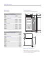
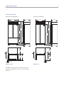
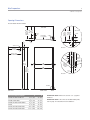
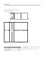
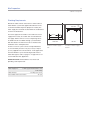
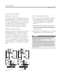
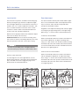
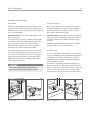
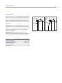
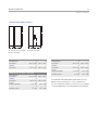
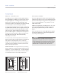
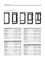
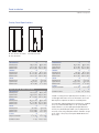
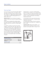
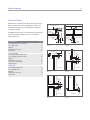
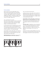
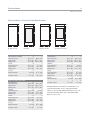
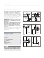
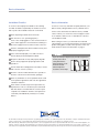
INSTALLATION GUIDE
Built-In Refrigeration
Contents
Important Note
Built-In Refrigeration . . . . . . . . . . . . . . . . . . . . . . . . . . . . . 3
To ensure the safe and efficient installation of Sub-Zero
equipment, please take note of the following types of
highlighted information throughout this guide:
Model Specifications . . . . . . . . . . . . . . . . . . . . . . . . . . . . 4
Site Preparation . . . . . . . . . . . . . . . . . . . . . . . . . . . . . . . . . 8
Built-In Installation . . . . . . . . . . . . . . . . . . . . . . . . . . . . . 16
Framed Panel Installation . . . . . . . . . . . . . . . . . . . . . . . . 22
Overlay Panel Installation . . . . . . . . . . . . . . . . . . . . . . . . 26
Flush Inset Panel Installation . . . . . . . . . . . . . . . . . . . . . 30
Side Panel Installation . . . . . . . . . . . . . . . . . . . . . . . . . . 35
Dual Installation . . . . . . . . . . . . . . . . . . . . . . . . . . . . . . . . 36
Service Information . . . . . . . . . . . . . . . . . . . . . . . . . . . . . 39
Features and specifications are subject to change at any time
without notice. Visit subzero.com/specs for the most up-todate information.
IMPORTANT NOTE: Throughout this guide, dimensions in
parentheses are millimeters unless otherwise specified.
IMPORTANT NOTE highlights information that is especially
relevant to a problem-free installation.
CAUTION signals a situation where minor injury or product
damage may occur if instructions are not followed.
WARNING states a hazard that may cause serious injury or
death if precautions are not followed.
Built-In Refrigeration
3
subzero.com/specs
Sub-Zero Built-In Refrigeration
Before You Start
The importance of the installation of the Sub-Zero built-in
unit cannot be overemphasized. Installation should be
done by a qualified installer.
Make sure that the actual equipment that was shipped to
you matches the design you are expecting to install. The
Sub-Zero built-in line offers the following design alternatives: framed, overlay, flush inset and stainless steel
models.
Before you begin the installation process, it is recommended that you read this entire installation guide. There
are key details that you should take special care to
observe during the installation. By reading these instructions carefully, you will make the installation process
easier, problem-free and most importantly, safe.
Any questions or problems regarding the installation
should be directed to your authorized Sub-Zero dealer or
Sub-Zero customer care at 800-222-7820. You may also
check the contact & support section of our website,
subzero.com.
Important product information, including the model and
serial numbers of the built-in unit are listed on the product
rating plate, located on the top frame of the unit inside the
door. Refer to the illustration below.
Each of these design options has specific installation
requirements, which means it is vital that the unit match
your planning and space needs. Before you begin the
installation process, check the exact model number you
need against the model number on the shipping carton.
If the unit you receive does not match your requirements,
contact your authorized Sub-Zero dealer.
TOOLS AND MATERIALS REQUIRED
• Appliance dolly able to support 700 lbs (317 kg) and
adequate manpower to handle the weight of the unit.
• Phillips and slotted screwdrivers.
• Torx drive screwdriver set.
• Allen, standard and crescent wrenches.
RATING
PLATE
• Various sized pliers.
•
3/8"
hex bolt nut driver.
• Cordless drill and assorted drill bits.
• Level—2' (.6 m) and 4' (1.2 m) recommended.
• 4' (1.2 m) of 1/4" copper, braided stainless steel or
PEX tubing and saddle valve for water line (do not use
self-piercing valves).
• Tubing cutter.
Location of rating plate.
• Masonite, plywood, pressed fiberboard, cardboard or
other suitable material to protect finished flooring.
• Appropriate materials to cover and protect the home
and furnishings during installation.
Model Specifications
4
Specifications
Overall Dimensions
BUILT-IN MODELS
ALL REFRIGERATOR / ALL FREEZER MODELS
Interior Capacity
R cu ft (L)
F cu ft (L)
36" (914)
24" (610)
ALL REFRIGERATOR / ALL FREEZER MODELS
BI-36R
BI-36RG
BI-36F
23.5 (665)
23.4 (663)
22.7 (643)
OVER-AND-UNDER MODELS
BI-30U
BI-30UG
BI-36U
BI-36UG
BI-36UFD
13.2 (374)
13.1 (371)
16.4 (464)
16.3 (462)
15.7 (445)
4.2 (119)
4.2 (119)
5.3 (150)
5.3 (150)
5.3 (150)
12.4 (351)
16.3 (462)
15.8 (447)
16.0 (453)
19.1 (541)
18.6 (527)
18.8 (532)
8.2 (232)
8.0 (227)
7.9 (224)
7.9 (224)
9.8 (278)
9.6 (272)
9.6 (272)
84"
(2134)
73 3/4"
(1873)
SIDE-BY-SIDE MODELS
BI-36S
BI-42S
BI-42SID
BI-42SD
BI-48S
BI-48SID
BI-48SD
Shipping Weight
lbs (kg)
HEIGHT DIMENSIONS ± 1/2" (13)
4" (102)
ALL REFRIGERATOR / ALL FREEZER MODELS
BI-36R
BI-36RG
BI-36F
420 (191)
430 (195)
406 (184)
23 7/8"
(606)
OVER-AND-UNDER MODELS
BI-30U
BI-30UG
BI-36U
BI-36UG
BI-36UFD
23 7/8" (606)
462 (210)
476 (216)
515 (234)
529 (240)
529 (240)
17"
(432)
37 1/4"
(946)
SIDE-BY-SIDE MODELS
BI-36S
BI-42S
BI-42SID
BI-42SD
BI-48S
BI-48SID
BI-48SD
538 (244)
582 (264)
608 (276)
608 (276)
630 (286)
656 (298)
656 (298)
2 3/8" (60)
MODELS BI-36R, BI-36RG AND BI-36F
Shipping weights and overall dimensions are based on
stainless steel models. For flush inset applications, add
1/2" (13) to door clearance dimensions.
Model Specifications
5
subzero.com/specs
Overall Dimensions
OVER-AND-UNDER MODELS
30" (762)
24" (610)
36" (914)
24" (610)
84"
84"
(2134)
(2134)
50 3/4"
50 3/4"
(1289)
(1289)
23"
23"
(584)
(584)
HEIGHT DIMENSIONS ± 1/2" (13)
4" (102)
HEIGHT DIMENSIONS ± 1/2" (13)
23 7/8" (606)
23 7/8"
23 7/8"
(606)
(606)
4" (102)
14 1/2"
17"
(368)
(432)
23 5/8"
(600)
311/4"
(796)
23 5/8"
(600)
37 1/4"
(946)
2 3/8" (60)
2 3/8" (60)
MODELS BI-30U AND BI-30UG
MODELS BI-36U AND BI-36UG
23 7/8" (606)
Model Specifications
6
Overall Dimensions
OVER-AND-UNDER MODELS
SIDE-BY-SIDE MODELS
36" (914)
24" (610)
36" (914)
24" (610)
84"
84"
(2134)
(2134)
50 3/4"
(1289)
73 3/4"
(1873)
23"
(584)
HEIGHT DIMENSIONS ± 1/2" (13)
4" (102)
HEIGHT DIMENSIONS ± 1/2" (13)
23 7/8" (606)
4" (102)
23 7/8"
23 7/8"
(606)
(606)
7 3/4"
81/2"
101/4"
(197)
(216)
(260)
191/2" 23 5/8"
(495)
221/4"
(600)
(565)
2 3/8" (60)
MODEL BI-36UFD
Overall dimensions are based on stainless steel models.
For flush inset applications, add 1/2" (13) to door clearance
dimensions.
2 3/8" (60)
MODEL BI-36S
23 7/8" (606)
Model Specifications
7
subzero.com/specs
Overall Dimensions
SIDE-BY-SIDE MODELS
42" (1067)
24" (610)
48" (1219)
24" (610)
84"
84"
(2134)
(2134)
73 3/4"
73 3/4"
(1873)
(1873)
HEIGHT DIMENSIONS ± 1/2" (13)
4" (102)
HEIGHT DIMENSIONS ± 1/2" (13)
23 7/8" (606)
4" (102)
23 7/8"
23 7/8"
(606)
(606)
8 3/4"
12 1/2"
9 3/4"
14"
(222)
(318)
(248)
(356)
26 1/4"
30"
(668)
(762)
2 3/8" (60)
2 3/8" (60)
MODELS BI-42S, BI-42SID AND BI-42SD
MODELS BI-48S, BI-48SID AND BI-48SD
23 7/8" (606)
Site Preparation
8
Opening Dimensions
STANDARD INSTALLATION
TOP VIEW
24" (610)
OPENING
DEPTH
24" (610)
OPENING DEPTH
83 3/4"
A
(2127)
OPENING
HEIGHT
OPENING WIDTH
SIDE VIEW
FRONT VIEW
Opening Width
A
BI-36R, BI-36RG and BI-36F
35 1/2"
BI-30U and BI-30UG
29 1/2" (746)
BI-36U, BI-36UG and BI-36UFD
35 1/2"
BI-36S
35 1/2" (902)
(902)
(902)
BI-42S, BI-42SID and BI-42SD
411/2" (1054)
BI-48S, BI-48SID and BI-48SD
47 1/2" (1206)
IMPORTANT NOTE: If two units are installed side by side,
refer to page 10 for dual standard installations.
Stainless steel models are ready to install out of the box.
Site Preparation
9
subzero.com/specs
Opening Dimensions
3
FLUSH INSET INSTALLATION
TOP VIEW
26 3/16" 24" (610)
DEPTH
(665)
FLUSH TO CLEAT
INSET
DEPTH
11/4"
(32)
UNIT WITH
3/4" (19) PANEL
CLEAT
26 3/16" 24" (610)
TOP VIEW
OPENING
(665)
DEPTH
FLUSH
INSET TO CLEAT
DEPTH
CLEAT
3" (76)
typical
DETAIL A
2 3/16" (56)
2 3/16"
1/4"
(6)
(56)
11/4"
(32)
CLEAT
24" (610)
DEPTH TO CLEAT
Detail A
2 3/16"
(56)
26 3/16" (665)
FLUSH INSET DEPTH
3" typical
(76)
CLEAT
4" (102)
83 3/4"
(2127)
HEIGHT
TO CLEAT
A
11/4"
11/4"
WIDTH TO CLEAT
(32)
(32)
84"
B
(2134)
FLUSH
INSET
HEIGHT
FLUSH INSET WIDTH
24" (610)
OPENING
DEPTH TO
CLEAT
SHADED
AREA
MUST BE
FINISHED
2 3/16" (56)
11/4"
(32)
Detail B
DETAIL B
SIDE VIEW
FRONT VIEW
Flush Inset Opening Widths
A
B
BI-36R, BI-36RG and BI-36F
35 1/2" (902)
38" (965)
BI-30U and BI-30UG
29 1/2" (746)
32" (813)
BI-36U, BI-36UG and BI-36UFD
35 1/2"
(902)
38" (965)
BI-36S
35 1/2" (902)
38" (965)
BI-42S, BI-42SID and BI-42SD
411/2"
(1054)
44" (1118)
BI-48S, BI-48SID and BI-48SD
47 1/2" (1206)
50" (1270)
IMPORTANT NOTE: Dimensions assume a 3/4" (19) panel
thickness.
IMPORTANT NOTE: If two units are installed side by side,
refer to page 11 for dual flush inset installations.
Site Preparation
10
Dual Installation Opening Dimensions
STANDARD INSTALLATION
TOP VIEW
24" (610)
OPENING
DEPTH
24" (610)
OPENING DEPTH
83 3/4"
A
(2127)
OPENING
HEIGHT
OPENING WIDTH
SIDE VIEW
FRONT VIEW
Opening Widths
A
Two 30" (762) Models
59 3/4"
30" (762) and 36" (914) Models
65 3/4" (1670)
Two 36" (914) Models
71 3/4"
(1518)
(1822)
IMPORTANT NOTE: A dual installation kit will be required for
this installation.
Stainless steel models are ready to install out of the box.
Site Preparation
11
subzero.com/specs
Dual Installation Opening Dimensions
3
FLUSH INSET INSTALLATION
TOP VIEW
26 3/16" 24" (610)
DEPTH
(665)
FLUSH TO CLEAT
INSET
DEPTH
11/4"
(32)
TWO UNITS WITH
3/4" (19) PANEL
CLEAT
26 3/16" 24" (610)
TOP VIEW
OPENING
(665)
DEPTH
FLUSH
INSET TO CLEAT
DEPTH
CLEAT
3" (76)
typical
DETAIL A
2 3/16" (56)
2 3/16"
1/4"
(6)
(56)
11/4"
CLEAT
(32)
24" (610)
DEPTH TO CLEAT
Detail A
2 3/16"
(56)
26 3/16" (665)
FLUSH INSET DEPTH
3" typical
(76)
CLEAT
83 3/4"
(2127)
HEIGHT
TO CLEAT
4" (102)
A
11/4"
11/4"
WIDTH TO CLEAT
(32)
SHADED
AREA
MUST BE
FINISHED
(32)
84"
B
(2134)
FLUSH
INSET
HEIGHT
FLUSH INSET WIDTH
24" (610)
OPENING
DEPTH TO
CLEAT
2 3/16" (56)
11/4"
(32)
Detail B
DETAIL B
SIDE VIEW
Opening Widths
FRONT VIEW
A
B
Two 30" (762) Models
59 3/4" (1518) 62 1/4" (1581)
30" (762) and 36" (914) Models
65 3/4" (1670) 68 1/4" (1734)
Two 36" (914) Models
71 3/4" (1822) 74 1/4" (1886)
IMPORTANT NOTE: Dimensions assume a 3/4" (19) panel
thickness. A dual installation kit will be required for this
installation.
Site Preparation
12
Site Preparation
Electrical Requirements
Make sure that the finished rough opening where the
built-in unit is being installed is properly prepared. Refer to
the overall dimensions and installation specifications for
your specific model. These specifications are identical for
the framed, overlay and stainless steel applications.
Installation specifications are different for the flush inset
application, whether you are using custom panels or
Sub-Zero accessory flush inset panels.
For all built-in models, the electrical supply should be
located within the shaded area shown in the illustration.
Follow the National Electrical Code and local codes and
ordinances when installing the receptacle. A separate
circuit, servicing only this appliance is required. A ground
fault circuit interrupter (GFCI) is not recommended and
may cause interruption of operation.
Make sure the opening dimensions, door and drawer
clearances, electrical service and plumbing are correct for
the model you are about to install. The floor under the unit
must be level with the surrounding finished floor.
To operate properly, the door must open a minimum of
90°. Use a minimum 3" (76) filler in corner installations to
assure a 90° door opening. Allow enough clearance in
front of the unit for full door swing.
If you are installing two built-in units side by side in the
framed, overlay, flush inset or stainless steel application, a
separating filler strip is recommended. Add the filler strip
width to the finished rough opening dimension.
For installation of two built-in units side by side without a
filler strip, a dual installation kit will be necessary.
Electrical Requirements
Power Supply
115 V AC, 60 Hz
Circuit Breaker
15 amp
Receptacle
3-prong grounding-type
The outlet must be checked by a qualified electrician to
be sure that it is wired with the correct polarity. Verify
that the outlet is properly grounded.
Do not use an extension cord or two-prong adapter.
Do not remove the power supply cord ground prong.
FRONT VIEW
7"
(178)
E
6"
(152)
75 1/2"
(1918)
FROM
FLOOR
Location of electrical supply.
Site Preparation
13
subzero.com/specs
Plumbing Requirements
All built-in models with an automatic ice maker feature a
water filtration system that supplies filtered water to the
ice maker and water dispenser (dispenser models). The
water supply line should be located within the shaded area
shown in the illustrations.
The water supply line should be connected to the house
supply with an easily accessible shut-off valve between
the supply and the unit. Do not use self-piercing valves.
A saddle valve kit is available through your authorized
Sub-Zero dealer. The water line must not interfere with
installation of the anti-tip brackets.
A reverse osmosis system can be used provided there
is constant water pressure of 35 psi (2.4 bar) to 120 psi
(8.3 bar) supplied to the unit at all times. In this application,
the water filtration system must be bypassed. Refer to
water filter bypass mode on page 21. A copper line is not
recommended for this application.
IMPORTANT NOTE: All installations must meet local
plumbing code requirements.
Plumbing Requirements
Water Supply Line
1/4"
OD copper, braided stainless steel
or PEX tubing
Water Pressure
Excess Water Line for Connection
35–120 psi (2.4–8.3 bar)
36" (914)
BACK WALL
18" (457)
1/2"
(13)
6"
(152)
18" (457)
6"
(152)
3" (76)
FLOOR
FRONT VIEW
Location of water supply—
rear.
TOP VIEW
Location of water supply—
bottom.
Site Preparation
14
Anti-Tip Bracket Installation
To prevent the unit from tipping forward and provide
a stable installation, the unit must be secured in place
with the anti-tip brackets provided.
IMPORTANT NOTE: Placement of the anti-tip brackets is
critical to a stable installation. Failure to properly position
the anti-tip brackets will prevent them from engaging the
unit.
The two anti-tip brackets must be installed exactly 24"
(610) from the front of the rough opening to the back of the
brackets and a minimum of 4" (102) from the sides of the
rough opening. This depth will increase to 26 3/16" (665) for
a flush inset installation based on 3/4" (19) deep decorative
panels. Proper placement will ensure that the anti-tip
brackets engage the anti-tip bar at the back of the unit.
To properly secure the anti-tip brackets for a stable installation, use all anti-tip bracket hardware as instructed for
wood or concrete floors.
Anti-Tip Bracket Hardware
2
12
4
12
Anti-tip brackets
#12 x 2 1/2" PH pan HD zinc screws
3/8"–16
x 3 3/4" wedge anchors
#12 flat washers
4
#8–18 x 11/4" PH truss HD screws
4
Nylon zip-it wall anchors
IMPORTANT NOTE: For either wood or concrete floor
applications, if the #12 x 2 1/2" screws do not hit a wall
stud or the wall plate in any of the back holes of the
brackets, use the provided #8–18 x 1 1/4" PH truss HD
screws and #12 flat washers with the nylon zip-it wall
anchors.
IMPORTANT NOTE: In some installations the subflooring
or finished floor may necessitate angling the screws used
to fasten the anti-tip brackets to the back wall.
Make sure there are no electrical wires or plumbing
in the area which the screws could penetrate.
Site Preparation
15
subzero.com/specs
Anti-Tip Bracket Installation
WOOD FLOOR APPLICATIONS
INSTALL CONCRETE WEDGE ANCHORS:
After properly locating the anti-tip brackets in the rough
opening, drill pilot holes 3/16" (5) diameter maximum in the
wall studs or wall plate. Use the #12 x 2 1/2" PH pan HD
zinc screws and #12 flat washers to secure the brackets in
place. Make sure the screws penetrate through the
flooring material and into wall studs or wall plate a
minimum of 3/4" (19). Refer to the illustration below.
1) Drill a 3/8" (10) diameter hole any depth exceeding the
minimum embedment. Clean the hole or continue
drilling additional depth to accommodate drill fines.
Use a carbide drill bit manufactured within ANSI
B94.12-77.
CONCRETE FLOOR APPLICATIONS
After properly locating the anti-tip brackets in the rough
opening, drill pilot holes 3/16" (5) diameter maximum in
the wall studs or wall plate. Then drill 3/8" (10) diameter
holes into the concrete a minimum of 11/2" (38) deep.
Use the #12 x 2 1/2" PH pan HD zinc screws and #12 flat
washers to secure the brackets to the wall and use the
3/8"–16 x 3 3/4" wedge anchors to secure the brackets to
the floor. Make sure the screws penetrate the wall studs or
wall plate a minimum of 3/4" (19). Refer to the illustration
below.
24"
(610)
4" (102)
4" (102)
MIN
MIN
FINISHED
FLOORING
FINISHED
FLOORING
WALL PLATE
SUBFLOORING
WOOD FLOOR
Wood floor.
24"
(610)
WALL PLATE
SUBFLOORING
CONCRETE
FLOOR
Concrete floor.
11/2"(38)
min
MIN
2) Assemble the washer and nut flush with the end of
anchor to protect threads. Drive the anchor through the
material to be fastened until the washer is flush with
the surface material.
3) Expand the anchor by tightening the nut 3–5 turns past
hand-tight position or to 25 foot-pounds of torque.
Always wear safety glasses and use other necessary
protective devices or apparel when installing or
working with anchors.
Anchors are not recommended for use in lightweight
masonry material such as block or brick, or for use in
new concrete which has not had sufficient time to cure.
The use of core drills is not recommended to drill holes
for the anchors.
Built-In Installation
16
Unpack the Unit
Grille Removal
Uncrate the built-in unit and inspect for any damages.
Remove the wood base and discard the shipping bolts
and brackets that hold the wood base to the bottom of the
unit. Remove and discard all packing materials.
In order to prevent damage to the grille and to access the
power cord, the top grille assembly should be removed
prior to moving the unit.
IMPORTANT NOTE: Do not discard the kickplate, anti-tip
brackets and hardware. These items will be needed for
installation.
Retract the front leveling legs all the way up to allow the
unit to be moved into position more easily. You will extend
the front leveling legs down and make adjustments once
the unit is in position.
Remove the drain pan from the base of the unit to avoid
damage to the drain pan, and allow for proper placement
of the appliance dolly.
To remove the grille assembly, pull out on the bottom edge
of the grille and tilt upward. Loosen the back two grille
mounting screws and remove the front two grille mounting
screws. Refer to the illustrations below. With the grille held
firmly, pull forward to remove.
To reinstall the grille, insert the grille into position and
make sure the grille catch tabs are engaged. Reinstall the
front two grille screws, then retighten the back two grille
screws. Check for proper fit.
GRILLE HEIGHT ADJUSTMENT
The grille was designed to rest on the upper door hinge(s)
to minimize the reveal between the top of the door and
bottom of the grille. To eliminate potential interference of
the grille and hinge, the grille height can be adjusted.
Loosen the four grille adjustment screws (two on each
side) and adjust the grille height as needed. For screw
location, refer to the illustration below.
BACK GRILLE
SCREW
LOCATION
OF GRILLE
ADJUSTMENT
SCREWS
FRONT
GRILLE SCREW
Grille removal.
Grille mounting screws.
Built-In Installation
17
subzero.com/specs
Position the Unit
Before moving the built-in unit into position, secure
door(s) closed and protect any finished flooring.
Use an appliance dolly to move the unit near the rough
opening. Each built-in unit is equipped with rollers, so it
can be moved into position more easily. If possible, keep
the door(s) closed until the unit is properly anchored.
The rear levelers must be in their lowest position in order
to roll the unit back into the rough opening. Leveling
cannot be completed until the unit is in position.
Shut off power to the electrical outlet. Plug the power cord
into the grounded outlet and roll the unit into position.
Make sure the anti-tip brackets are properly engaged.
IMPORTANT NOTE: If for any reason the unit has been
laid on its back or side, you must allow the unit to stand
upright for a minimum of 24 hours before connecting
power.
IMPORTANT NOTE: If used, side panels will need to be
installed before the unit is placed in its final position. Refer
to page 35.
Water Line Connection
Approximately 3' (.9 m) of 1/4" plastic tubing is connected
to the unit with a preassembled 1/4" compression connection at the end. This tubing is located under the unit.
The water line fitting connection kit, provided with the unit,
contains a 1/4" compression union fitting for connection to
the household water line. Place the sleeve and nut on the
water line and fasten to the connection at the end of the
tubing under the unit. Do not over tighten. Check all water
line fittings for leaks. Make sure the drain pan can be
removed without water line interference.
Purge the water line prior to final connection to the unit.
This will remove any debris that may be present in the
tubing from installing the new water line.
IMPORTANT NOTE: If a reverse osmosis system used,
it is recommended that the water filtration system be
bypassed. Refer to water filter bypass mode on page 21.
IMPORTANT NOTE: Let your customer know that the ice
maker will not produce ice immediately, and that the first
few batches of ice produced should be discarded. Allow
24 hours for proper ice production.
IMPORTANT NOTE: Water lines must not be exposed to
freezing temperatures. Exposure could cause damage to
the unit and home.
Built-In Installation
18
Level the Unit
Door Adjustment
Once the unit is in position, extend the front leveling legs
down by turning the legs clockwise to adjust the height.
The rear height adjustment can be made from the front of
the base. Use a 3/8" socket to adjust the rear rollers. Turn
the 3/8" hex bolt clockwise to raise the unit or counterclockwise to lower it. Refer to the illustration below for
location of the rear roller base adjustment.
The doors for built-in side-by-side models and the upper
door on over-and-under models can be adjusted in three
ways: in and out, side to side tilt, and up and down
(except over-and-under models).
When the unit is properly leveled, door and drawer adjustments are less likely to be necessary.
IMPORTANT NOTE: Be sure to reference leveling of the
unit to the floor and not surrounding cabinetry. This could
affect the operation of the unit, such as door closing.
To reduce the possibility of the unit tipping forward,
the front leveling legs must be in contact with the floor.
Regardless of the adjustment being made, start by slightly
loosening the two upper hinge bolts on the upper hinge
plate using a 1/2" wrench. Refer to the illustration below.
IN AND OUT ADJUSTMENT
Refer to the illustration below for location of the bolt for in
and out door adjustment. To adjust a left-hinge door;
using a 5/32" allen wrench, turn the bolt clockwise to bring
the handle side of the door inward, and counterclockwise
to move the handle side of the door outward. Reverse the
directions for a right-hinge door.
SIDE TO SIDE TILT ADJUSTMENT
INSTALL LIGHT DIFFUSER
To install, align the slots of the light diffuser onto the
bracket pegs under the control panel. Then pull forward
fully so the tabs on the slots engage the pegs on the
bracket. Refer to the illustration below.
Refer to the illustration below for location of the bolt for
side to side tilt door adjustment. To adjust a left-hinge
door; using a 3/8" wrench, turn the bolt clockwise to raise
the handle side of the door up and counterclockwise to tilt
the handle side of the door down. Reverse the directions
for a right-hinge door.
UPPER
HINGE BOLTS
IN AND OUT
ADJUSTMENT
PEG
SLOT
FRONT
LEVELING LEG
SIDE TO SIDE
TILT ADJUSTMENT
REAR
ADJUSTMENT
Rear roller base adjustment.
Light diffuser.
Upper hinge bolts.
Door adjustment bolts.
Built-In Installation
19
subzero.com/specs
Door Adjustment
Panel Installation
DOOR HEIGHT ADJUSTMENT
If your customer has ordered either a framed or overlay
model, you will be installing door panel(s) to give the unit
the custom Sub-Zero look. Before you begin installing
panels, refer to the panel specifications for framed,
overlay or flush inset applications on pages 22–34, and
make sure you are working with the panel design called
for in your installation.
To adjust a left-hinge door; using a 1/4" allen wrench, turn
the bolt clockwise to raise the door and counterclockwise
to lower the door. Refer to the illustration below. Reverse
the directions for a right-hinge door.
IMPORTANT NOTE: For overlay models, there are two
design applications, overlay and flush inset. Be sure to
use the correct panel sizes for your application.
If your customer has chosen the stainless steel design, the
unit has been shipped complete with a finished stainless
steel look. It will not be necessary to install door panels or
handle hardware. In your final preparation for stainless
steel units, use a stainless steel cleaner to remove any
marks. Abrasive cleaners should not be used, as they may
scratch the surface.
Door height adjustment.
Built-In Installation
20
Complete the Installation
ANCHORING
INSTALL KICKPLATE
After door and side panels have been installed, the unit
has been leveled and door adjustment completed, anchor
the built-in unit to the opening. This will assure a proper fit
and a secure installation.
Make sure the drain pan is in the proper position before
installing the kickplate. To install, screw the kickplate to
brackets attached to the inside surface of each roller
base. Refer to the illustration below.
IMPORTANT NOTE: Be sure to level and square the unit
before anchoring it.
IMPORTANT NOTE: The kickplate must be removable for
service. The floor cannot interfere with removal. Refer to
the label mounted on the kickplate support for height
clearance.
To anchor the top of the unit to cabinetry, open the grille,
and install the screws provided through the grille frame
into the cabinetry. There are several hole locations
provided. Check for proper door clearance by fully
opening the door. Refer to the illustration below.
To anchor the bottom of the unit, drive a screw through
the side hole inside the roller base assembly. There is one
on each side. The screw will need to go in at an angle in
order to attach properly. Refer to the illustration below.
Additional material may be needed behind the cleat to
ensure sufficient anchoring.
If the screws provided are not suitable for your
application, you must provide adequate screws.
Reinstall the grille following the instructions on page 16.
Turn power back on to the electrical outlet.
90° DOOR STOP
The doors of all built-in models open to 110°. A 90° door
stop is provided with the unit (located behind the grille) for
installations where the door opening must be limited.
Additional 90° door stop kits are available through your
authorized Sub-Zero dealer.
The 90° door stop will be installed in the top hinge. To
install, open the door to approximately 90°. At the top of
the door, insert the door stop between the door hinge and
the door closer arm. Insert the screw through the door
stop and into the door as shown in the illustration below.
ANCHORING
SCREWS
ANCHORING
SCREW
Top anchoring.
Bottom anchoring.
Kickplate installation.
90° door stop.
Built-In Installation
21
subzero.com/specs
Water Filtration System
Air Purification System
WATER FILTER BYPASS MODE
All Sub-Zero built-in units, except model BI-36F, come
with an advanced air purification system. A factory
installed air purification cartridge is located inside the
refrigerator section, on the right-hand side of the back
wall. For information regarding use and removal of this
cartridge, refer to the built-in use & care guide provided
with the unit.
If you choose not to use the water filtration system, the
system can be placed in water filter bypass mode by
simply removing the water filter cartridge. Refer to the
illustration below for location of the water filter. Follow
these steps to remove the water filter cartridge:
1) To access the water filter, pull out on the bottom edge
of the grille assembly and tilt the grille frame forward.
2) To remove the cartridge, simply rotate the cartridge
counterclockwise one-quarter turn and pull it out.
Refer to the illustration below.
WATER FILTER
WATER
FILTER
Location of water filter.
Water filter cartridge removal.
The air purification system complies with applicable
Federal requirements regarding incidental exposure
to ultraviolet light. Lamp contains mercury. Manage in
accordance with disposal laws. Go to earth911.org or
call 800-222-7820.
Panel Installation
22
Framed Panels
If your customer has chosen a framed design application,
make sure that the panels you are about to install match
dimensions listed in the framed panel specifications on
pages 24–25. Additional panel design information can be
found in the Sub-Zero design guide and on our website,
subzero.com.
TRIM
REVEAL
1/4" (6) min
1/4" (6)
MAIN FRAME
DOOR
TRIM
REVEAL
1/4" (6) min
ROUT TO
1/4" (6)
MAIN FRAME
DOOR
PANEL
If the thickness of the custom panel is less than a 1/4" (6),
back it up with a sheet of shim material to build the total
thickness to a 1/4" (6). If the panel is thicker than a 1/4" (6),
rout an edge around the panel to achieve a proper fit.
Refer to the illustrations.
IMPORTANT NOTE: On all built-in models, routing,
recessing or optional extended handles may be required
on raised panels for finger clearance under the handle.
Framed Panel Requirements
MAX WEIGHT PER PANEL
BI-36R, BI-36RG and BI-36F
All Other Framed Models
75 lbs (34 kg)
50 lbs (23 kg)
MIN PANEL THICKNESS
All Framed Panels
1/4"
(6)
Panels 1/4" (6) thick or less.
Panels thicker than 1/4" (6).
Panel Installation
23
subzero.com/specs
Framed Panels
To install framed panels, the door handle(s) must be
removed. To install framed panels, first remove the door
trim molding. For side-by-side models and the upper door
for over-and-under models, insert a screwdriver tip into
the top corner slot on the handle side and pop out the trim
molding. Refer to the illustration below.
For the drawer on over-and-under models, insert a screwdriver tip into the slot on either side of the trim molding
running along the top of the drawer, and pop out the trim
molding. Refer to the illustration below.
With a screwdriver, remove the handles from the freezer
and refrigerator doors. Slide the panel into the frame on
the door. With the panel in position, replace the handles.
Make sure the panel is inserted completely into the
channel for proper fit and alignment.
To reinstall the trim molding, insert the top of the trim
molding into the grooves at the top of the door and work
downward, snapping the trim molding into the clips on the
handle.
For the drawer on over-and-under models, start at one
end and move towards the opposite end, snapping the
trim molding into the clips on the handle.
Door trim.
Over-and-under drawer trim.
RAISED PANELS
You may have to rout, recess or use optional extended
handles with some door panel designs to allow for finger
clearance. This is particularly true if your unit has raised
panels greater than 1/4" (6) total thickness.
IMPORTANT NOTE: Do not exceed the maximum per
panel weight for your specific model. Refer to the chart on
the previous page.
Check the location of offset when you are using specific
routing for the grip area only. Refer to the Sub-Zero design
guide for a full-scale template of the standard full-length
handle and panel. Use this grid template to lay out your
panel design for finger clearance when standard fulllength handles are used.
Panel Installation
24
Framed Panel Specifications
A
H
A
A
H
A
H
A
A
H
H
W
A
H
W
H
H
B
W
BI-36R / BI-36F
W
W
BI-36RG
BI-30U / BI-36U
Models BI-36R, BI-36RG and BI-36F
REFRIGERATOR/FREEZER
Door Panel
BI-36RG
W
BI-30UG / BI-36UG
W
BI-36UFD
Models BI-36U and BI-36UG
W
H
35 3/4" (908)
69 9/16" (1767)
W
H
Window Cut-Out
25 1/2" (648)
54 1/16" (1373)
A
B
Cut-Out Location
5 3/16" (132)
10 5/16" (262)
REFRIGERATOR
Door Panel
FREEZER
Drawer Panel
BI-36UG
Window Cut-Out
W
H
35 3/4" (908)
49 15/16" (1268)
W
H
35 3/4" (908)
18 11/16" (475)
W
H
25 1/2" (648)
39 11/16" (1008)
A
5 3/16" (132)
Cut-Out Location
Models BI-30U and BI-30UG
REFRIGERATOR
Door Panel
FREEZER
Drawer Panel
BI-30UG
Window Cut-Out
W
H
29 3/4" (756)
49 15/16" (1268)
W
H
29 3/4" (756)
18 11/16" (475)
W
H
19 1/2" (495)
39 11/16" (1008)
A
Cut-Out Location
5 3/16" (132)
Model BI-36UFD
REFRIGERATOR (2 PANELS)
Door Panels
FREEZER
Drawer Panel
W
H
17 5/8" (448)
49 15/16" (1268)
W
H
35 3/4" (908)
18 11/16" (475)
Panel Installation
25
subzero.com/specs
Framed Panel Specifications
H
H
A
B
W
W
BI-36S / BI-42S / BI-42SID
BI-48S / BI-48SID
W
W
BI-42SD / BI-48SD
Model BI-36S
Models BI-48S, BI-48SID and BI-48SD
REFRIGERATOR
Door Panel
W
H
19 13/16" (503)
69 9/16" (1767)
FREEZER
Door Panel
W
H
15 7/16" (392)
69 9/16" (1767)
REFRIGERATOR
Door Panel
FREEZER
Door Panel
BI-48SD
Dispenser Cut-Out
Models BI-42S, BI-42SID and BI-42SD
REFRIGERATOR
Door Panel
FREEZER
Door Panel
BI-42SD
Dispenser Cut-Out
Cut-Out Location
W
H
24 13/16" (630)
69 9/16" (1767)
W
H
16 7/16" (418)
69 9/16" (1767)
W
H
5 7/8" (149)
12 7/16" (316)
A
B
1 7/8" (48)
28 3/4" (730)
Cut-Out Location
W
H
28 1/2" (724)
69 9/16" (1767)
W
H
18 3/4" (476)
69 9/16" (1767)
W
H
5 7/8" (149)
12 7/16" (316)
A
B
1 7/8" (48)
28 3/4" (730)
For models BI-42SD and BI-48SD, panel thickness in the
dispenser area can range from 1/4" (6) to a maximum of
1 1/8" (29). If the panel is thicker, you must rout out a minimum
1/4" (6) flat landing area to accommodate the glasswell bezel.
Panel Installation
26
Overlay Panels
If your customer has chosen an overlay design application, make sure that the panels you are about to install
match dimensions listed in the overlay panel specifications on pages 28–29. Additional panel design information
can be found in the Sub-Zero design guide and on our
website, subzero.com.
IMPORTANT NOTE: The size of the overlay panel is
critical. It must fit over the door frame. Also, do not
exceed the maximum per panel weight for your specific
model. Refer to the chart below.
Overlay models are shipped without handle hardware.
The cabinet manufacturer or designer will need to provide
handle hardware to match the overall decorating scheme.
To install overlay panels, first remove the door trim
molding. For side-by-side models and the upper door for
over-and-under models, insert a screwdriver tip into the
top corner slot on the handle side and pop out the trim
molding. Remove the screws and frame. For the drawer
on over-and-under models, insert a screwdriver tip into
the slot on either side of the trim molding running along
the top of the drawer and pop out the trim molding.
Remove the screws and frame. Refer to the illustrations
on page 23.
Sub-Zero allows a 1/4" (6) space to slide the backing
material into place in the frame. If your material is thicker
than a 1/4" (6), either rout an edge around the panel to get
a proper fit or mount the decorative overlay panel on a
sheet of 1/4" (6) thick material and insert the backing
material into the channel.
You must allow for .10" (3) space between the backer
board and the decorative panel, so the panel will slide
easily into the door frame.
The illustrations below provide a cross section view of the
three-panel assembly, showing placement of the trim and
a rear view of the three-panel assembly with critical
dimensions, standard for all built-in models.
Install the handle hardware before inserting the panel. We
recommend larger D-style pulls. The use of small, onepiece knobs is not recommended. If you use screws with
thick heads, you will need to countersink the screws into
the backer panel before sliding the assembly into place.
Slide the panel into the frame on the door. With the panel
in position, replace the frame end. Make sure the panel is
inserted completely into the channel for proper fit and
alignment.
To reinstall the trim molding on side-by-side models and
the upper door for over-and-under models, insert the top
of the trim molding into the grooves at the top of the door
and work downward, snapping the trim molding into the
clips on the frame.
For the drawer on over-and-under models, start at one
end and move towards the opposite end, snapping the
trim molding into the clips on the frame.
OVERLAY
PANEL
SPACER PANEL
SPACER
PANEL
OVERLAY PANEL
Overlay Panel Requirements
BACKER PANEL
MAX WEIGHT PER PANEL
BI-36R, BI-36RG and BI-36F
All Other Overlay Models
Grille Panel
75 lbs (34 kg)
50 lbs (23 kg)
13 lbs (6 kg)
5/16" (8) min
MIN PANEL THICKNESS
All Overlay Panels
5/8"
(16)
BACKER
PANEL
TRIM
1/8"
(3)
Panel assembly cross
section.
3/ 4 "
(19)
typical
.10" (3) 1/4" (6)
Panel assembly rear view.
Panel Installation
27
subzero.com/specs
Overlay Panels
MODELS BI-42SD AND BI-48SD
GRILLE PANEL ASSEMBLY
The dispenser area of models BI-42SD and BI-48SD has
been engineered to enable the use of the overlay or flush
inset panel application. Installing overlay or flush inset
panels for these models is the same procedure as for
other built-in models. The refrigerator door panel will need
to accommodate a cut-out for the glasswell bezel.
Remove the grille panel assembly as described on page
16. Remove the top two corner screws and pull away the
top frame. Slide the panel into position in the grille frame.
If you are using a grille panel 1/4" (6) or thinner, you will
need to install a filler.
To remove the glasswell bezel for an overlay or flush inset
model BI-42SD or BI-48SD, the water grille and touch pad
must be removed. Lift the water grille up and out. Next,
remove the touch pad assembly by removing the center
plastic mandrel supports. Carefully tilt the touch pad out
and disconnect the wire harness (blue side up) from the
back side of the touch pad. Remove the bezel by
removing the four screws.
Insert the overlay or flush inset panel into the door trim.
Reverse the procedure to install the bezel, touch pad and
water grille. To install the plastic rivets, insert rivets
through the touch pad and into the control housing and
secure by pressing mandrels into the body of the rivets.
Refer to the illustrations below.
IMPORTANT NOTE: The total panel thickness (including
backer and spacer, if used) in the glasswell bezel area can
range from 1/4" (6) to a maximum of 1 1/8" (29). If the panel
is thicker, provisions must be made to rout out a space to
accommodate the bezel surrounding the glasswell.
ICE
WATER
LOCK
INDICATOR
LIGHT
WATER
GRILLE
BEZEL
Dispenser glasswell bezel.
Glasswell bezel removal.
Reattach the top frame by reinstalling the two top corner
screws. Install the grille panel assembly onto the unit,
by reversing the grille removal procedure outlined on
page 16.
Refer to specifications for overlay grille panels on pages
28–29 and the illustrations on the previous page for the
exact sizing of all three panels.
Do not exceed the panel dimensions listed for the
appropriate overlay grille panel you are specifying. The
overlay decorative panel cannot be any larger or it may
restrict the air flow to the compressor area and cause
problems with the operation of the Sub-Zero unit.
Panel Installation
28
Overlay Panel Specifications
H
H
H
A
H
A
H
H
H
H
A
A
H
H
A
A
W
A
H
W
H
H
B
W
BI-36R / BI-36F
W
W
BI-36RG
BI-30U / BI-36U
Overlay Panel
Spacer Panel
Backer Panel
GRILLE
Overlay Panel
Spacer Panel
Backer Panel
BI-36RG
BI-30UG / BI-36UG
W
BI-36UFD
Models BI-36U and BI-36UG
Models BI-36R, BI-36RG and BI-36F
REFRIGERATOR / FREEZER
W
W
H
36" (914)
35 1/8" (892)
35 3/4" (908)
69 3/4" (1772)
68 15/16" (1751)
69 9/16" (1767)
W
H
36" (914)
35 1/8" (892)
35 3/4" (908)
9 1/4" (235)*
8 5/16" (211)
8 15/16" (227)
W
H
Window Cut-Out
25 1/2" (648)
54 1/8" (1375)
A
B
Cut-Out Location
5 1/4" (133)
10 3/8" (264)
REFRIGERATOR
Overlay Panel
Spacer Panel
Backer Panel
FREEZER
Overlay Panel
Spacer Panel
Backer Panel
GRILLE
Overlay Panel
Spacer Panel
Backer Panel
BI-36UG
Window Cut-Out
W
H
36" (914)
35 1/8" (892)
35 3/4" (908)
50 1/8" (1273)
49 5/16" (1253)
49 15/16" (1268)
W
H
36" (914)
35 1/8" (892)
35 3/4" (908)
19" (483)
18 1/16" (459)
18 11/16" (475)
W
H
36" (914)
35 1/8" (892)
35 3/4" (908)
9 1/4" (235)*
8 5/16" (211)
8 15/16" (227)
W
H
25 1/2" (648)
39 5/8" (1006)
Models BI-30U and BI-30UG
REFRIGERATOR
Overlay Panel
Spacer Panel
Backer Panel
FREEZER
Overlay Panel
Spacer Panel
Backer Panel
GRILLE
Overlay Panel
Spacer Panel
Backer Panel
BI-30UG
Window Cut-Out
A
W
H
30" (762)
29 1/8" (740)
29 3/4" (756)
50 1/8" (1273)
49 5/16" (1253)
49 15/16" (1268)
W
H
30" (762)
29 1/8" (740)
29 3/4" (756)
19" (483)
18 1/16" (459)
18 11/16" (475)
W
H
30" (762)
29 1/8" (740)
29 3/4" (756)
9 1/4" (235)*
8 5/16" (211)
8 15/16" (227)
W
H
19 1/2" (495)
39 5/8" (1006)
A
Cut-Out Location
5 1/4" (133)
5 1/4" (133)
Cut-Out Location
Model BI-36UFD
REFRIGERATOR (2 PANELS)
Overlay Panels
Spacer Panels
Backer Panels
FREEZER
Overlay Panel
Spacer Panel
Backer Panel
GRILLE
Overlay Panel
Spacer Panel
Backer Panel
W
H
17 7/8" (454)
17" (432)
17 5/8" (448)
50 1/8" (1273)
49 5/16" (1253)
49 15/16" (1268)
W
H
36" (914)
35 1/8" (892)
35 3/4" (908)
19" (483)
18 1/16" (459)
18 11/16" (475)
W
H
36" (914)
35 1/8" (892)
35 3/4" (908)
9 1/4" (235)*
8 5/16" (211)
8 15/16" (227)
Panel Installation
29
subzero.com/specs
Overlay Panel Specifications
H
H
H
H
A
B
W
W
BI-36S / BI-42S / BI-42SID
BI-48S / BI-48SID
W
W
BI-42SD / BI-48SD
Model BI-36S
Models BI-48S, BI-48SID and BI-48SD
REFRIGERATOR
Overlay Panel
Spacer Panel
Backer Panel
W
H
20 1/16" (510)
19 3/16" (487)
19 13/16" (503)
69 3/4" (1772)
68 15/16" (1751)
69 9/16" (1767)
FREEZER
Overlay Panel
Spacer Panel
Backer Panel
W
H
15 11/16" (398)
14 13/16" (376)
15 7/16" (392)
69 3/4" (1772)
68 15/16" (1751)
69 9/16" (1767)
GRILLE
Overlay Panel
Spacer Panel
Backer Panel
W
H
36" (914)
35 1/8" (892)
35 3/4" (908)
9 1/4" (235)*
8 5/16" (211)
8 15/16" (227)
REFRIGERATOR
Overlay Panel
Spacer Panel
Backer Panel
FREEZER
Overlay Panel
Spacer Panel
Backer Panel
GRILLE
Overlay Panel
Spacer Panel
Backer Panel
BI-48SD
Dispenser Cut-Out
Models BI-42S, BI-42SID and BI-42SD
REFRIGERATOR
Overlay Panel
Spacer Panel
Backer Panel
FREEZER
Overlay Panel
Spacer Panel
Backer Panel
GRILLE
Overlay Panel
Spacer Panel
Backer Panel
BI-42SD
Dispenser Cut-Out
Cut-Out Location
W
H
25 1/16" (637)
24 3/16" (614)
24 13/16" (630)
69 3/4" (1772)
68 15/16" (1751)
69 9/16" (1767)
W
H
16 11/16" (424)
15 13/16" (402)
16 7/16" (418)
69 3/4" (1772)
68 15/16" (1751)
69 9/16" (1767)
W
H
42" (1067)
41 1/8" (1045)
41 3/4" (1060)
9 1/4" (235)*
8 5/16" (211)
8 15/16" (227)
W
H
5 7/8" (149)
12 7/16" (316)
A
B
2" (51)
28 13/16" (732)
Cut-Out Location
W
H
28 3/4" (730)
27 7/8" (708)
28 1/2" (724)
69 3/4" (1772)
68 15/16" (1751)
69 9/16" (1767)
W
H
19" (483)
18 1/8" (460)
18 3/4" (476)
69 3/4" (1772)
68 15/16" (1751)
69 9/16" (1767)
W
H
48" (1219)
47 1/8" (1197)
47 3/4" (1213)
9 1/4" (235)*
8 5/16" (211)
8 15/16" (227)
W
H
5 7/8" (149)
12 7/16" (316)
A
B
2" (51)
28 13/16" (732)
*Height of overlay panel for grille may be increased by 1/2" (13)
to hide upper main frame. For more information, refer to the
built-in panel configurator at subzero.com/trade/panels.
For all models, grille panel dimensions listed are for standard
84" (2134) nominal finished height. For 83" (2108) finished
height, subtract 1" (25) from grille panel height dimensions.
For 88" (2235) finished height, add 4" (102) to grille panel. An
83" (2108) or 88" (2235) panel grille must be ordered to accept
an 83" (2108) or 88" (2235) custom panel. Width dimensions
do not vary.
Panel Installation
30
Flush Inset Panels
If your customer has chosen the flush inset panel application, make sure that the panels you are about to install
match dimensions listed in the flush inset panel specifications on pages 32–33. Additional panel design information
can be found in the Sub-Zero design guide and on our
website, subzero.com.
Sub-Zero allows a 1/4" (6) space to slide the backing
material into place in the frame. If your material is thicker
than a 1/4" (6), either rout an edge around the panel to get
a proper fit or mount the decorative flush inset panel on a
sheet of 1/4" (6) thick material and insert the backing
material into the channel.
IMPORTANT NOTE: The size of the flush inset panel is
critical. It must be sized correctly for a proper fit inside the
opening.
You must allow for 0.10" (3) space between the backer
board and the decorative panel, so the panel will slide
easily into the door frame.
Overlay models are shipped without handle hardware.
The cabinet manufacturer or designer will provide handle
hardware at the job site to match the overall decorating
scheme.
The illustration below provides a rear view of the threepanel assembly with critical dimensions, standard for all
built-in models.
To install flush inset panels, first remove the door trim
molding. For side-by-side models and the upper door for
over-and-under models, insert a screwdriver tip into the
top corner slot on the handle side and pop out the trim
molding. Remove the screws and frame. For the drawer
on over-and-under models, insert a screwdriver tip into
the slot on either side of the trim molding running along
the top of the drawer, and pop out the trim molding.
Remove the screws and frame. Refer to the illustrations
on page 23.
IMPORTANT NOTE: With the panels installed, 1/2" (13)
minimum reveals must be kept on all sides to ensure
proper door opening and sufficient cooling of the unit.
FLUSH INSET
PANEL
SPACER
PANEL
BACKER
PANEL
Flush Inset Panel Requirements
MAX WEIGHT PER PANEL
BI-36R, BI-36RG and BI-36F
All Other Flush Inset Models
Grille Panel
75 lbs (34 kg)
50 lbs (23 kg)
13 lbs (6 kg)
MIN PANEL THICKNESS
All Flush Inset Panels
5/8"
(16)
3 /4"
(19)
typical
.10" (3) 1/4" (6)
Three-panel assembly.
Panel Installation
31
subzero.com/specs
Flush Inset Panels
Install the handle hardware before inserting the panel.
Sub-Zero recommends using larger D-style pulls. The use
of small, one-piece knobs is not recommended. If you use
screws with thick heads, you will need to countersink the
screws into the backer panel before sliding the assembly
into place.
Slide the panel into the frame on the door. With the panel
in position, replace the frame end. Make sure the panel is
inserted completely into the channel for proper fit and
alignment.
To reinstall the trim molding on side-by-side models and
the upper door for over-and-under models, insert the top
of the trim molding into the grooves at the top of the door
and work downward, snapping the trim molding into the
clips on the frame.
For the drawer on over-and-under models, start at one
end and move towards the opposite end, snapping the
trim molding into the clips on the frame.
GRILLE PANEL ASSEMBLY
Remove the grille panel assembly as described on page
16. Remove the top two corner screws and pull away the
top frame. Slide the panel into position in the grille frame.
If you are using a grille panel 1/4" (6) or thinner, you will
need to install a filler.
Reattach the top frame by reinstalling the two top corner
screws. Install the inner grille panel assembly onto the
unit, by reversing the grille removal procedure outlined on
page 16.
Refer to specifications for flush inset grille panels on
pages 32–33 and the illustrations on the previous page for
the exact sizing of all three panels.
Do not exceed the panel dimensions listed for the
appropriate flush inset grille panel you are specifying.
The flush inset decorative panel cannot be any larger
or it may restrict the air flow to the compressor area
and cause problems with the operation of the Sub-Zero
unit.
Panel Installation
32
Flush Inset Panel Specifications
H
H
H
A
H
A
H
H
H
H
B
A
H
H
A
A
W
B
H
W
H
H
B
W
BI-36R / BI-36F
W
W
BI-36RG
BI-30U / BI-36U
Models BI-36R, BI-36RG and BI-36F
REFRIGERATOR / FREEZER
Flush Inset Panel
Spacer Panel
Backer Panel
GRILLE
Flush Inset Panel
Spacer Panel
Backer Panel
BI-36RG
W
BI-30UG / BI-36UG
H
37" (940)
35 1/8" (892)
35 3/4" (908)
69 3/4" (1772)
68 15/16" (1751)
69 9/16" (1767)
W
H
37" (940)
35 1/8" (892)
35 3/4" (908)
9 1/4" (235)
8 5/16" (211)
8 15/16" (227)
W
H
25 1/2" (648)
54 1/8" (1375)
A
B
Cut-Out Location
5 3/4" (146)
10 3/8" (264)
REFRIGERATOR
Flush Inset Panel
Spacer Panel
Backer Panel
FREEZER
Flush Inset Panel
Spacer Panel
Backer Panel
GRILLE
Flush Inset Panel
Spacer Panel
Backer Panel
BI-36UG
FREEZER
Flush Inset Panel
Spacer Panel
Backer Panel
GRILLE
Flush Inset Panel
Spacer Panel
Backer Panel
BI-30UG
W
H
31" (787)
29 1/8" (740)
29 3/4" (756)
50 1/8" (1273)
49 5/16" (1253)
49 15/16" (1268)
W
H
31" (787)
29 1/8" (740)
29 3/4" (756)
19" (483)
18 1/16" (459)
18 11/16" (475)
W
H
31" (787)
29 1/8" (740)
29 3/4" (756)
9 1/4" (235)
8 5/16" (211)
8 15/16" (227)
W
H
Window Cut-Out
19 1/2" (495)
39 5/8" (1006)
A
B
Cut-Out Location
5 3/4" (146)
5 1/4" (133)
W
H
37" (940)
35 1/8" (892)
35 3/4" (908)
50 1/8" (1273)
49 5/16" (1253)
49 15/16" (1268)
W
H
37" (940)
35 1/8" (892)
35 3/4" (908)
19" (483)
18 1/16" (459)
18 11/16" (475)
W
H
37" (940)
35 1/8" (892)
35 3/4" (908)
9 1/4" (235)
8 5/16" (211)
8 15/16" (227)
W
H
Window Cut-Out
25 1/2" (648)
39 5/8" (1006)
A
B
Cut-Out Location
5 3/4" (146)
5 1/4" (133)
Models BI-30U and BI-30UG
Flush Inset Panel
Spacer Panel
Backer Panel
BI-36UFD
Models BI-36U and BI-36UG
W
Window Cut-Out
REFRIGERATOR
W
Model BI-36UFD
REFRIGERATOR (2 PANELS)
Flush Inset Panels
Spacer Panels
Backer Panels
FREEZER
Flush Inset Panel
Spacer Panel
Backer Panel
GRILLE
Flush Inset Panel
Spacer Panel
Backer Panel
W
H
18 3/8" (467)
17" (432)
17 5/8" (448)
50 1/8" (1273)
49 5/16" (1253)
49 15/16" (1268)
W
H
37" (940)
35 1/8" (892)
35 3/4" (908)
19" (483)
18 1/16" (459)
18 11/16" (475)
W
H
37" (940)
35 1/8" (892)
35 3/4" (908)
9 1/4" (235)
8 5/16" (211)
8 15/16" (227)
Panel Installation
33
subzero.com/specs
Flush Inset Panel Specifications
H
H
H
H
A
B
W
W
BI-36S / BI-42S / BI-42SID
BI-48S / BI-48SID
W
W
BI-42SD / BI-48SD
Models BI-48S, BI-48SID and BI-48SD
Model BI-36S
REFRIGERATOR
Flush Inset Panel
Spacer Panel
Backer Panel
W
H
20 9/16" (522)
19 3/16" (487)
19 13/16" (503)
69 3/4" (1772)
68 15/16" (1751)
69 9/16" (1767)
FREEZER
Flush Inset Panel
Spacer Panel
Backer Panel
W
H
16 3/16" (411)
14 13/16" (376)
15 7/16" (392)
69 3/4" (1772)
68 15/16" (1751)
69 9/16" (1767)
GRILLE
Flush Inset Panel
Spacer Panel
Backer Panel
W
H
37" (940)
35 1/8" (892)
35 3/4" (908)
9 1/4" (235)
8 5/16" (211)
8 15/16" (227)
REFRIGERATOR
Flush Inset Panel
Spacer Panel
Backer Panel
FREEZER
Flush Inset Panel
Spacer Panel
Backer Panel
GRILLE
Flush Inset Panel
Spacer Panel
Backer Panel
BI-48SD
Dispenser Cut-Out
Models BI-42S, BI-42SID and BI-42SD
REFRIGERATOR
Flush Inset Panel
Spacer Panel
Backer Panel
FREEZER
Flush Inset Panel
Spacer Panel
Backer Panel
GRILLE
Flush Inset Panel
Spacer Panel
Backer Panel
BI-42SD
Dispenser Cut-Out
Cut-Out Location
W
H
25 9/16" (649)
24 3/16" (614)
24 13/16" (630)
69 3/4" (1772)
68 15/16" (1751)
69 9/16" (1767)
W
H
17 3/16" (437)
15 13/16" (402)
16 7/16" (418)
69 3/4" (1772)
68 15/16" (1751)
69 9/16" (1767)
W
H
43" (1092)
41 1/8" (1045)
41 3/4" (1060)
9 1/4" (235)
8 5/16" (211)
8 15/16" (227)
W
H
5 7/8" (149)
12 7/16" (316)
A
B
2" (51)
28 13/16" (732)
Cut-Out Location
W
H
29 1/4" (743)
27 7/8" (708)
28 1/2" (724)
69 3/4" (1772)
68 15/16" (1751)
69 9/16" (1767)
W
H
19 1/2" (495)
18 1/8" (460)
18 3/4" (476)
69 3/4" (1772)
68 15/16" (1751)
69 9/16" (1767)
W
H
49" (1245)
47 1/8" (1197)
47 3/4" (1213)
9 1/4" (235)
8 5/16" (211)
8 15/16" (227)
W
H
5 7/8" (149)
12 7/16" (316)
A
B
2" (51)
28 13/16" (732)
For all models, grille panel dimensions listed are for standard
84" (2134) nominal finished height. For 83" (2108) finished
height, subtract 1" (25) from grille panel height dimensions.
For 88" (2235) finished height, add 4" (102) to grille panel. An
83" (2108) or 88" (2235) panel grille must be ordered to accept
an 83" (2108) or 88" (2235) custom panel. Width dimensions
do not vary.
Panel Installation
34
C
5
Flush Inset Panels
Illustrations A–F provide panel offsets and reveals for all
D the
built-in models in a flush inset application. Refer to
chart below for reference to the illustrations relating to
your specific model.
T
TOP VIEW
TOP VIEW
DOOR / DRAWER / GRILLE
DOOR
BACKER
SPACER
For additional information on model specific panel reveals,
visit the specification library section of our website,
subzerotrade.com.
FLUSH INSET PANEL
5/16" (8)
Panel Offsets
DOOR
CABINETRY
1/2"
(13)
5/16" (8)
1/8" (3)
5/8"
(16)
Illus.
1/4" (6)
REVEAL
ALL REFRIGERATOR / ALL FREEZER
Door / Grille Sides
Grille Top
Grille Bottom / Door Top
Door Bottom
A
C
D
F
Illus. A
Illus. B
CABINETRY
1/2" (13)
OVER-AND-UNDER
Door (hinge) / Drawer / Grille Sides
Doors (handle) Sides (French door)
Grille Top
Grille Bottom / Door Top
Door Bottom / Drawer Top
Drawer Bottom
A
B
C
D
E
F
GRILLE
5/16"
(8) 5/32"
(4)
GRILLE
1/8"
5/16" (3)
(8)
1/2" (13)
DOOR
3/32"
5/16" (2)
(8)
SIDE-BY-SIDE
Doors (hinge) / Grille Sides
Doors (handle) Sides
Grille Top
Grille Bottom / Door Top
Door Bottom
A
B
C
D
F
SIDE VIEW
Illus. C
SIDE VIEW
S
Illus. D
S
DOOR /
DRAWER
5/16"
(8) 3/32"
(2)
DOOR
5/8" (16)
DRAWER
5/16"
(8)
5/32"
5/16" (4)
(8)
SIDE VIEW
Illus. E
S
SIDE VIEW
Illus. F
5
3/32"
(2)
SIDE VIEW
Panel Installation
35
subzero.com/specs
Side Panels
IMPORTANT NOTE: Side panels will need to be installed
before the unit is placed in its final position.
When installing a built-in unit with a custom side panel,
an accessory kit is required. Stainless steel and white
enamel side panels are available through your authorized
Sub-Zero dealer. Refer to instructions included with the
side panel kit when installing these side panels. For local
dealer information, visit the find a showroom section of
our website, subzero.com.
IMPORTANT NOTE: The use of side panels may change
the width of your rough opening.
CUSTOM SIDE PANEL INSTALLATION
The custom side panel will need to be a minimum of 24"
(610) deep and 1/2" (13) thick. Routing will be necessary for
the side panel to fit flush against the side of the unit. Refer
to the illustrations below.
24" (610)
IMPORTANT NOTE: The overall height on the side panel
will vary with the height of the grille being used. Make sure
you know your finished height before cutting any panels.
Install the brackets provided in the kit onto the side panel
in the locations shown in the illustration below. The front
brackets are meant to engage the mainframe and the back
brackets will wrap behind the unit when the panel is in
place. Screws are provided in the kit. If the provided
screws will not work for your installation, you will need to
provide the necessary screws to attach the brackets.
IMPORTANT NOTE: If you have a model BI-30U, BI-30UG,
BI-36U, BI-36UG or BI-36UFD, extra routing will be necessary to avoid having the panel hit the refrigerator lower
hinge plate.
Place the panel at a 75° angle and engage the front
brackets into the mainframe. Swing the panel inward,
making sure that the front brackets engage the mainframe.
With the panel in position, attach the rear brackets to the
rear of the unit with the screws provided. Check to see
that the panel is secure. Refer to the illustration below.
FRONT
OF SIDE
PANEL
1" (25)
1 7/8" (48)
FRONT
BRACKET
1/8" (3)
ROUT TO 1/8" (3)
1/2" (13)
SIDE PANEL
1 7/8"(48)
84"
1" (25)
MAIN
FRAME
(2134)
SIDE PANEL
ROUTING
MAIN
REAR
FRAME
BRACKET
Routing detail.
4 1/4" (108)
ROUT TO
3/16" (5)
(OVER-AND-UNDER
MODELS)
5 3/4"
(146)
20 1/2"
(521)
4" (102)
OPTIONAL
TOE KICK
CUT-OUT
2 5/8"
(67)
Side panel dimensions.
Side panel attachment
(top view).
Dual Installation
36
Dual Installation
When two built-in units are installed side by side, a
Sub-Zero built-in dual installation kit may be required.
Contact your authorized Sub-Zero dealer for the proper
components and installation instructions. For questions
regarding the installation, call Sub-Zero at 800-222-7820.
For local dealer information, visit the find a showroom
section of our website, subzero.com.
DUAL STANDARD INSTALLATIONS
Two framed, overlay or stainless steel units may be placed
side by side in a dual installation. Some dual standard
installations will require a dual installation kit, available
through your authorized Sub-Zero dealer.
A custom filler strip can be used in between two units in a
framed, overlay or stainless steel design application. It is
recommended that the filler strip be at least 2" (51) wide,
to prevent condensation between the units. Be sure to add
the filler strip width to your rough opening width.
Dual installations without a filler strip can only be accomplished using two units with opposite hinges as shown in
illustration A below. The dual installations shown in illustrations B and C require a filler strip.
IMPORTANT NOTE: For the application shown in illustration A, a dual installation accessory kit is required.
WITHOUT FILLER STRIP
Illus. A
FILLER STRIP REQUIRED
Illus. B
FILLER STRIP REQUIRED
Illus. C
DUAL FLUSH INSET INSTALLATIONS
Installing two built-in models side by side in a flush inset
application will require adjustments to the dimensions of
your finished rough opening, panel sizes and panel offsets.
It will also require a dual installation kit, available through
your authorized Sub-Zero dealer.
Dual installations without a filler strip can only be accomplished using two units with opposite hinges as shown in
illustration A below. The dual installations shown in illustrations B and C require a filler strip. Illustration A is the
only application that will accommodate the dual wide
grille.
IMPORTANT NOTE: The application shown in illustration A
can only be achieved by installing dual flush inset panels.
Failure to install dual flush inset panels will cause the
handle side of the panels to collide when closing. In this
application a dual installation accessory kit is also
required.
Dual flush inset panels and dual installation kits are available through your authorized Sub-Zero dealer. Refer to the
following page for dual flush inset panel specifications.
Dual Installation
37
subzero.com/specs
Dual Installation—Flush Inset Panel Specifications
H
H
H
H
A
H
B
A
A
H
H
A
A
H
B
H
H
B
W
BI-36R / BI-36F
W
W
BI-36RG
BI-30U / BI-36U
Models BI-36R, BI-36RG and BI-36F
REFRIGERATOR / FREEZER
Flush Inset Panel
Spacer Panel
Backer Panel
GRILLE
Flush Inset Panel
Spacer Panel
Backer Panel
BI-36RG
W
BI-30UG / BI-36UG
Models BI-36U and BI-36UG
W
H
36 1/2" (927)
35 1/8" (892)
35 3/4" (908)
69 3/4" (1772)
68 15/16" (1751)
69 9/16" (1767)
W
H
36 1/2" (927)
35 1/8" (892)
35 3/4" (908)
9 1/4" (235)
8 5/16" (211)
8 15/16" (227)
W
H
Window Cut-Out
25" (635)
54 1/8" (1375)
A
B
Cut-Out Location
5 3/4" (146)
10 3/8" (264)
REFRIGERATOR
Flush Inset Panel
Spacer Panel
Backer Panel
FREEZER
Flush Inset Panel
Spacer Panel
Backer Panel
GRILLE
Flush Inset Panel
Spacer Panel
Backer Panel
BI-36UG
Flush Inset Panel
Spacer Panel
Backer Panel
FREEZER
Flush Inset Panel
Spacer Panel
Backer Panel
GRILLE
Flush Inset Panel
Spacer Panel
Backer Panel
BI-30UG
W
H
30 1/2" (775)
29 1/8" (740)
29 3/4" (756)
50 1/8" (1273)
49 5/16" (1253)
49 15/16" (1268)
W
H
30 1/2" (775)
29 1/8" (740)
29 3/4" (756)
19" (483)
18 1/16" (459)
18 11/16" (475)
W
H
30 1/2" (775)
29 1/8" (740)
29 3/4" (756)
9 1/4" (235)
8 5/16" (211)
8 15/16" (227)
W
H
Window Cut-Out
19" (483)
39 5/8" (1006)
A
B
Cut-Out Location
5 3/4" (146)
5 1/4" (133)
H
50 1/8" (1273)
49 5/16" (1253)
49 15/16" (1268)
W
H
36 1/2" (927)
35 1/8" (892)
35 3/4" (908)
19" (483)
18 1/16" (459)
18 11/16" (475)
W
H
36 1/2" (927)
35 1/8" (892)
35 3/4" (908)
9 1/4" (235)
8 5/16" (211)
8 15/16" (227)
W
H
Window Cut-Out
25" (635)
39 5/8" (1006)
A
B
Cut-Out Location
5 3/4" (146)
5 1/4" (133)
Models BI-30U and BI-30UG
REFRIGERATOR
W
36 1/2" (927)
35 1/8" (892)
35 3/4" (908)
Grille panel dimensions listed are for standard 84" (2134)
nominal finished height. For 83" (2108) finished height,
subtract 1" (25) from grille panel height dimensions. For 88"
(2235) finished height, add 4" (102) to grille panel. Width
dimensions do not vary.
Dual Installation
38
C
5
Dual Installation—Flush Inset Panels
When installing two built-in models side by side in a flush
inset application, you must decrease the width of the
decorative flush inset panels by 1/2" (13). Adjustments to
the panel offsets will also need to be made. These adjustments are needed to achieve a proper fit and to ensure the
panels do not collide when closing. Panel dimensions in
the chart below have been adjusted to reflect the
decrease in panel dimensions.
DUAL
TRIM
DOOR
BACKER
SPACER
FLUSH INSET PANEL
5/16" (8)
1/2"
(13)
5/16" (8)
1/8" (3)
5/8"
(16)
1/4" (6)
REVEAL
Illus. A
Illus. B
CABINETRY
1/2" (13)
For additional information on model specific panel reveals,
visit the specification library section of our website,
subzerotrade.com.
Panel Offsets
DOOR
CABINETRY
IMPORTANT NOTE: If a filler strip is not used, dual installations can only be accomplished using two units with
opposite hinges.
Illustrations A–F provide panel offsets and reveals for all
built-in models in a flush inset application. Refer to the
chart below for reference to the illustrations relating to
your specific model. All reveals are 1/2" (13) unless otherwise specified.
TOP VIEW
TOP VIEW
DOOR / DRAWER / GRILLE
GRILLE
5/16"
(8) 5/32"
(4)
GRILLE
1/8"
5/16" (3)
(8)
1/2" (13)
DOOR
Illus.
3/32"
5/16" (2)
(8)
SIDE VIEW
SIDE VIEW
S
ALL REFRIGERATOR / ALL FREEZER
Doors (hinge) / Grille Sides
Doors (handle) Sides
Grille Top
Grille Bottom / Door Top
Door Bottom
A
B
C
D
F
Illus. C
S
DOOR /
DRAWER
5/16"
(8) 3/32"
(2)
OVER-AND-UNDER
Doors (hinge) / Drawer / Grille Sides
Doors (handle) Sides
Grille Top
Grille Bottom / Door Top
Door Bottom / Drawer Top
Drawer Bottom
Illus. D
A
B
C
D
E
F
DOOR
5/8" (16)
DRAWER
5/16"
(8)
5/32"
5/16" (4)
(8)
SIDE VIEW
Do not exceed the flush inset decorative panel dimensions. Exceeding dimensions could cause damage to
the panels and the Sub-Zero unit.
Illus. E
S
SIDE VIEW
Illus. F
5
3/32"
(2)
SIDE VIEW
Service Information
39
Installation Checklist
Service Information
To ensure a safe and proper installation, the following
checklist should be completed by the installer to ensure
that no part of the installation has been overlooked.
If service is necessary, maintain the quality built into your
built-in unit by calling Sub-Zero factory certified service.
Have all packing materials been removed?
Turn the unit on. Is it operating properly?
If not, is the unit plugged in? Is the control turned on?
Is the water supply line connected and not leaking? Is
the water supply turned on and ice maker control on?
Have the anti-tip brackets been installed securely and
properly engaging the unit?
For the name and number of Sub-Zero factory certified
service nearest you, check the contact & support section
of our website, subzero.com or call Sub-Zero customer
care at 800-222-7820.
When calling for service, you will need the model and
serial numbers of your unit. Both numbers are listed on the
product rating plate, located at the top frame of the unit
inside the door. Refer to the illustration on page 3.
Is the unit leveled properly on a solid, level floor?
Has the drain pan and kickplate installed?
Are panels attached securely and properly aligned?
Are the door(s) aligned for proper appearance and
operation?
Has the water filter cartridge been removed (for homes
with a reverse osmosis system)?
If you are storing or disposing of your old refrigerator or
freezer, please do it
safely. Remove the
doors or tightly secure
the doors closed.
Child entrapment
accidents can be tragic.
Does the customer understand the unit's operation?
Does the customer have the warranty package?
Have any installation or service problems been noted
on the product registration card? Has the registration
card been mailed in?
Have stainless steel door(s) been inspected for any
imperfections? This is to be done by the authorized
Sub-Zero dealer or installer with the customer upon
completion of installation. Stainless steel panels are
covered by a limited 60-day warranty for cosmetic
defects.
The information and images in this guide are the copyright property of Sub-Zero, Inc. Neither this guide nor any information or images contained herein may be
copied or used in whole or in part without the express written permission of Sub-Zero, Inc. ©Sub-Zero, Inc. all rights reserved.
Wolf, Wolf & Design, Wolf Gourmet, W & Design and the color red as applied to knobs are registered trademarks and service marks of Wolf Appliance, Inc.
Sub-Zero, Sub-Zero & Design, Dual Refrigeration, Constant Care and The Living Kitchen are registered trademarks and service marks of Sub-Zero, Inc.
(collectively, the “Company Marks.”) All other trademarks or registered trademarks are property of their respective owners in the United States and other countries.
SUB-ZERO, INC.
P. O. BOX 44848
MADISON, WI 53744
7021793 REV-A
9/ 2011
SUBZERO.COM
800.222.7820