1
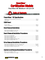
PowerWaveª
PowerWave MT Minitower 120/132/150
Table of Contents
PowerWaveª MT Specifications
Specifications for the PowerWave MT 120/132/150 ................................................................................Page 2
MLB Diagram ................................................................................................................................................Page 5
CUDA Reset
For Your Safety .............................................................................................................................................Page 3
Purpose of CUDA Reset...............................................................................................................................Page 4
Table of Contents
Certification Module
Bezel Removal/Installation
Removing and installing the chassis cover................................................................................................Page 6
Removing and installing the front bezel....................................................................................................Page 8
Board Removal/Installation Procedures
Removing and installing RAM...................................................................................................................Page 10
Removing and installing CPU card...........................................................................................................Page 12
Removing and installing L2 cache............................................................................................................Page 14
Removing and installing PCI expansion cards........................................................................................Page 15
Removing and installing PCI Riser card...................................................................................................Page 18
Drive Removal/Installation Procedures
Removing and installing drives in the rear 3.5-inch drive bay..............................................................Page 20
Removing and installing drives in the 5.25-inch drive bay....................................................................Page 22
Removing and installing the floppy disk drive ................................................................................................22
System Level Removal/Installation Procedures
Removing and installing the MLB.............................................................................................................Page 26
Removing and installing the power supply ............................................................................................Page 28
CONFIDENTIAL
1
2
CPU
PowerPC 604 at 120, 132 or 150MHz
Main Logic Board
Tsunami (Comparable to a Macintosh 9500)
CPU Upgrade
Available via daughtercard replacement
MacOS
7.5.2, 7.5.3, 7.5.5, 7.6, 7.6.1, 8.0
Memory
8 DIMM slotsÑ168-pin, 64 bit, 60 ns (1.24 Gb max); Memory interleaving
supported
Cache
512Kb Level 2
SCSI
SCSI: InternalÑ10MB/sec data transfer rate; ExternalÑ5 MB/sec data transfer rate
Serial Ports
High speed GeoPort-compatible 9-pin modem and printer ports
Network
Built-in Ethernet AAUI port; Built-in Ethernet 10 Base-T port;
LocalTalk serial connection via modem or printer port
Bus Expansion
Three PCI expansion slots
Floppy Drive
One 3.5-inch, 1.4MB floppy disk drive. Supports MacOS, Windows, DOS, OS/2
and ProDOS disk formats.
Video
No internal video. Ships standard with a high quality, accelerated video card with
both Mac and SVGA connections
Audio
16 bit, 44.1 KHz Stereo in/out connections (microphone port requires line-level
input, such as AppleÕs Plaintalk Microphone); Built-in speaker
ROM
Removable Apple ROM
Case style
Minitower
Drive Bays
Three front accessible, full-height 5.25-inch drive bay
Dimensions
7"(W) X 15"(H) X 16"(D); 22 lb (10.5 kg)
Power Supply
200W, 100V-240V (Domestic/International manual switching)
CONFIDENTIAL
PowerCenter LP Specifications
PowerWave MT Specifications
For Your Safety
To ensure your personal safety as well as prevent unnecessary damage to the computer, please follow all
safety precautions when performing any service on Power Computing computers.
Note: Always make sure that the computer is powered down before attempting any service. To make
sure that the computer is completely powered down, check the light behind the power button
on the front bezel and make sure that it is off.
Preventing ESD (Electrostatic Discharge) - There are two means by which a technician can maintain a
ground and eliminate ESD:
¥ wear an ESD wrist strap that is grounded to the computer
¥ power down the computer, but leave the CPU power cord plugged into the wall socket; touch the
metal case of the power supply to ensure complete static discharge before service.
Do not wear loose clothing or jewelry that may become caught in the components inside of the
computer case.
Make sure that the work environment is free from excessive moisture. Any moisture on the components
of the computer may cause damage.
If you need further assistance, please call:
1-800-708-6227
CONFIDENTIAL
3
The CUDA Reset button is a small red button located on the Main Logic Board. Depressing this button
resets the CUDA Microcontroller Chip. This chip is responsible for the following functions:
¥ Turns system power on and off
¥ Manages system resets from various commands
¥ Maintains parameter RAM
¥ Manages the Apple Desktop Bus (ADB)
¥ Manages the real-time clock
¥ Lets an external signal from either Apple GeoPort serial port control system power
It is rarely necessary to reset CUDA, but many problems that appear to be hardware related can be fixed
by doing so. Resetting CUDA will not harm the machine in any way. Some of the most common reasons
to reset CUDA are:
¥ After adding RAM, the machine will not boot, RAM does not show up in the memory control panel,etc.
¥ Machine will not power up
¥ Machine powers up, but does not chime or boot
¥ A serial port remains inaccessible even after booting without extensions, resetting parameter RAM, etc.
¥ Machine will power down for no apparent reason
¥ After adding any hardware to the inside of the machine
Resetting CUDA
1. Shut down the computer and disconnect all external devices, but leave the power cable plugged in to
ground the computer.
2. Remove the cover (refer to Chassis Cover Removal/Installation on page 6).
3. Touch the metal chassis of the machine. This will dissipate static electricity into ground.
4. Locate the CUDA Reset button (refer to MLB Diagram on page 5).
5. Press the CUDA Reset button for a few seconds.
6. Reboot, and verify resolution of the problem you wanted to solve.
Note: Resetting the CUDA will cause some system settings to default to factory settings.
4
CONFIDENTIAL
CUDA Reset
CUDA Reset
MLB
MLB Diagram
Diagram
5
CONFIDENTIAL
Removing the Chassis Cover
1. Shut down the computer and turn off all external devices. If you do not have a grounding strap,
leave the computer plugged into the wall socket. Leaving the computer plugged in ensures a
positive ground. Disconnect everything but the power cord.
2. Remove the large thumb screw from the rear of the computer (see Figure 1: Removing the on
page 6).
3. Gently pull the levers on the bottom corners of the cover outward. Slide the cover straight back
toward the rear of the machine, lift it off and set it aside.
Figure 1: Removing the
chassis cover
thumb screw
Installing the Chassis Cover
1. Standing at the front of the machine, slide the cover forward until the levers on the back corners lock
into place. Make sure the tabs on the front of the cover go under the bezel.
6
CONFIDENTIAL
Side Panel
Chassis Cover Removal/Installation
3. Reconnect the cables to the machine.
CONFIDENTIAL
Front Bezel
2. Screw the thumb screw into the rear of the chassis.
7
Front Bezel Removal/Installation
Removing the Front Bezel Cover
1. Remove the chassis cover (refer to Chassis Cover Removal/Installation on page 6).
2. Disengage the top three tabs that secure the bezel to the front of the computer (see Figure 2:
Disengage Bezel Tabs on page 9). All of these tabs must be disengaged before the front bezel can
be removed. The tabs are located on the inside of the chassis frame:
¥ one is on the top left end of the chassis
¥ one is on the top right end of the chassis
¥one is on the back of the chassis front panel, next to the power switch assembly
3. Disengage the bottom two tabs that secure the bezel to the front of the computer (see Figure 2:
Disengage Bezel Tabs on page 9). Both of these tabs must be disengaged before the front bezel
can be removed. The tabs are located on the inside of the chassis frame:
¥ one is on the inside left end of the chassis
¥ one is on the inside right end of the chassis
4. Lay the bezel face down directly in front of the chassis.
5. Disengage the wiring between the chassis and the front bezel.
CONFIDENTIAL
8
RAM
Bezel Tabs
Figure 2: Disengage
Bezel Tabs
Installing the Front Bezel
1. Connect the necessary wires to their respective ports on the main logic board.
2. Line up the two tabs on the bottom with the chassis and push them in until they click. Lift the
top edge of the bezel and line up the tabs with the chassis. Press the top edge of the front bezel
until the tabs click into place.
3. Replace the chassis cover (refer to Chassis Cover Removal/Installation on page 6).
CONFIDENTIAL
9
CPU
RAM Removal/Installation
Note: All DIMMs must be 168-pin, fast-paged mode, 70-nanosecond RAM access time or faster. The
PowerWave has eight DIMM slots near the front on the motherboard. The PowerWave supports
memory interleaving. For faster performance, install DIMMs in pairs (slot A1 and B1,etc).
Removing RAM
1. Remove the chassis cover (refer to Chassis Cover Removal/Installation on page 6).
2. Lay the computer on its side, open side up.
3. Locate the DIMM(s) you would like to remove (see Figure 3: on page 10). Loosen the desired
DIMM module by reaching in and pushing down on the small lever at the end of the DIMM slot.
(see Figure 4: Removing RAM on page 10). The DIMM should pop loose from the slot at the lever
end.
DIMM Slots
Figure 3:
DIMM slot
location
Figure 4: Removing RAM
4. Grasp the DIMM module on each end and evenly pull the module up and out of the slot.
Installing RAM
1. Hold the module (with the contacts down) with one hand at each end. Notice that there are two
notches in the contact edge of the DIMM module.
CONFIDENTIAL
10
CPU
2. Lower the DIMM squarely into the slot so that the notches in the DIMM line up with the notches
in the slot. Slide the contacts straight into the slot and make sure the contacts are firmly seated.
(see Figure 5: Installing RAM on page 11). When properly seated, the contacts on the bottom
should not be visible.
Figure 5: Installing RAM
Note: DonÕt force the DIMM module into the slot; if the MLB starts bending significantly, pull the
DIMM out, reposition it, and try again. If the DIMM module is seated correctly, the lever at the
end of the DIMM slot should be completely raised.
3. Reset the CUDA (refer to CUDA Reset on page 4).
4. Replace the chassis cover (refer to Chassis Cover Removal/Installation on page 6).
CONFIDENTIAL
11
CPU Removal/Installation
Removing the CPU
1. Remove the chassis cover (refer to Chassis Cover Removal/Installation on page 6).
1. Lay the machine on its side, open side up.
2. Remove the hex-head screw that secures the support beam to the rear of the chassis.
3. Swing the rear end of beam slightly up and out of chassis. Pull the beam towards rear of machine
to remove.
4. Place both hands on either side of the CPU card and lift up. Sometimes a gentle rocking motion
from end to end (not side to side) will make it easier to remove the CPU card.
PCI Riser Card
Retaining screw
Figure 9: CPU removal
CPU card
Installing the CPU
1. Hold the CPU card (contacts facing down) with one hand at each end. Notice that there is a notch in
CONFIDENTIAL
12
2. Lower the CPU card squarely into the slot so that the notch in the CPU card lines up with the
notch in the slot. Slide the contacts straight into the slot and make sure the contacts are firmly
seated. (see Figure 9: CPU removal on page 12). When properly seated, the contacts on the bottom
should not be visible.
Cache
the contact edge of the CPU card.
Note: DonÕt force the CPU card into the slot; if the MLB starts bending significantly, pull the CPU card
out, reposition it, and try again.
3. Reset the CUDA (refer to CUDA Reset on page 4).
4. Replace the support beam. First, fit the forward end of the stabilizer bar into the two small cutouts in the front panel of the metal case. Then, swing the bar down, aligning it with the riser card
and the processor card.
5. 5. Replace the chassis cover (refer to Chassis Cover Removal/Installation on page 6).
CONFIDENTIAL
13
Removing the Cache
1. Remove the chassis cover. (refer to Chassis Cover Removal/Installation on page 6).
2. Locate the cache card (refer to MLB Diagram on page 5).
Note: The level 2 cache is located between the CPU riser card and the front drive bay assembly. If you
believe that the area is too small to adequately grasp the cache card, remove the CPU riser before
removing the cache (refer to CPU Removal/Installation on page 12).
3. Place both hands on either side of the L2 cache card and lift up. Because the L2 cache is held in
by a tight pressure fit, sometimes a gentle rocking motion from end to end (not side to side)
will make it easier to remove the cache card.
Installing the Cache
1. Hold the L2 cache card (contacts facing down) with one hand at each end. Notice that there are
notches in the contact edge of the L2 cache card.
2. Lower the L2 cache card squarely into the slot so that the notches in the L2 cache card line up
with the notches in the slot. Slide the contacts straight into the slot and make sure the contacts
are firmly seated. When properly seated, the contacts on the bottom should not be visible.
Note: DonÕt force the L2 cache card into the slot; if the MLB starts bending significantly, pull the L2
cache card out, reposition it, and try again.
4. Reset the CUDA (refer to CUDA Reset on page 4).
5. Replace the chassis cover (refer to Chassis Cover Removal/Installation on page 6).
14
CONFIDENTIAL
PCI Cards
Cache Removal/Installation
PCI Cards Removal/Installation
Note: Before you install any expansion cards, be sure that the combined power consumption of the
expansion cards does not exceed the limits of the computer. Refer to the documentation that
came with the cards you are installing for their power consumption rating and to ÒPower
requirementsÓ in the UserÕs Guide for the power consumption limit for this computer.
Removing PCI Cards
1. Remove the chassis cover (refer to Chassis Cover Removal/Installation on page 6).
2. Lay the computer on its side, open side up.
3. Remove the bottom panel of the chassis. Remove the two screws on the bottom panelÕs left side.
Slide the bottom panel straight up to remove it.
4. Disconnect any cables that may be attached to the PCI card.
5. Remove the screw attaching the PCI card to the inside of the chassis.
6. Firmly grasp the PCI card and pull it straight out of the computer laterally. Be careful not to
damage any components that may be protruding through the I/O slot. Sometimes a gentle
rocking motion from end to end (not side to side) will make it easier to remove the PCI card.
Installing PCI Cards
1. Remove the chassis cover (refer to Chassis Cover Removal/Installation on page 6).
2. Lay the computer on its side, open side up.
3. Remove the bottom panel of the chassis. Remove the two screws on the bottom panelÕs left side.
Slide the bottom panel straight up to remove it.
4. Remove the retaining screw of the metal I/O slot cover from the slot you wish to use. (see Figure
10: Removing PCI slot cover on page 16).
5. Pull the I/O slot cover out the side so that the tongue at the bottom of the cover slides out of the
slot in the chassis.
15
CONFIDENTIAL
Figure 10: Removing PCI
slot cover
Slot cover screw
PCI slot cover
6. Hold the PCI card (contacts facing down) with one hand at each end. Notice that there is a notch
in the contact edge of the PCI card.
7. Lower the PCI card squarely into the PCI riser card so that the notch in the PCI card lines up with
the notch in the PCI riser card. Slide the contacts straight into the PCI riser card and make sure
the contacts are firmly seated. (see Figure 11: PCI card installation on page 16). When properly
seated, the contacts on the bottom should not be visible. Secure the PCI card to the chassis with
the retaining screw.
Figure 11: PCI card
installation
PCI card
Slot cover screw
Note: DonÕt force the PCI card into the slot; if the PCI riser card starts bending significantly, pull the
PCI card out, reposition it, and try again.
16
CONFIDENTIAL
3.5-inch Drive
PCI slot
8. Connect any wires or cables to the PCI card necessary for its proper operation.
9. Reset the CUDA (refer to CUDA Reset on page 4).
10. Replace the bottom chassis panel. Align the chips on the panelÕs right side with the notches in
the chassis. Slide the bottom panel into place and replace the screws on the panelÕs left side.
11. Replace the chassis cover (refer to Chassis Cover Removal/Installation on page 6).
17
CONFIDENTIAL
PCI Riser Card Removal/Installation
Removing the PCI Riser Card
1. Remove the chassis cover (refer to Chassis Cover Removal/Installation on page 6).
2. Locate the riser card (refer to MLB Diagram on page 5).
3. Remove any installed PCI cards (refer to PCI Cards Removal/Installation on page 15).
Figure 11:
PCI Riser Card Removal
4. Remove the hex-head screw that secures the support beam to the rear of the chassis.
5. Swing the rear end of beam slightly up and out of chassis. Pull the beam towards rear of machine
to remove.
6. Firmly grasp the PCI riser card and pull it straight out of the computer. Sometimes a gentle
rocking motion from end to end (not side to side) will make it easier to remove the PCI card.
Installing the PCI Riser Card
1. Lower the PCI riser card squarely into the PCI slot so that the notch in the PCI card lines up with the
notch in the PCI slot. Slide the contacts straight into the PCI slot and make sure the contacts are firmly
seated. When properly seated, the contacts on the bottom should not be visible.
CONFIDENTIAL
18
2. Replace the support beam. First, fit the forward end of the stabilizer bar into the two small cutouts in the front panel of the metal case. Then, swing the bar down, aligning it with the riser card
and the processor card. Replace the screw that attaches the beam to the back panel.
3. Reset the CUDA (refer to CUDA Reset on page 4).
4. Install the chassis cover (refer to Chassis Cover Removal/Installation on page 6).
19
CONFIDENTIAL
Removing the 3.5-inch Drive
1. Remove the chassis cover (refer to Chassis Cover Removal/Installation on page 6).
2. Remove the single screw that secures the drive cage to the back wall of the chassis. The cage will
swing up and out away from the computer.
Note: Be careful of the wires for the drive that are still connected.
Drive Cage retaining
screw
3.5-inch internal
drive bay
Figure 11:
Removing a 3.5-inch
internal drive bay
3. Disconnect the power cable and SCSI ribbon cable from any installed drives in the cage and
rotate the drive cage up and out of the chassis.
4. Remove the four mounting screws that secure the drive to the cage and slide the drive out.
Installing the 3.5-inch Drive
1. Slide the drive into the drive cage and line up the drive with the holes on the drive cage.
2. Replace the four screws that secure the drive to the drive cage.
3. Reconnect the power cable and SCSI ribbon cable for any installed drives in the cage.
20
CONFIDENTIAL
5.25-inch Drive
3.5-inch Drive Removal/Installation
4. The drive cage will swing down and into the computer. Replace the screw that secures the drive
cage to the back wall of the chassis.
5. Reset the CUDA (refer to CUDA Reset on page 4).
6. Install the chassis cover (refer to Chassis Cover Removal/Installation on page 6).
21
CONFIDENTIAL
Removing 5.25-inch Drives
1. Remove the chassis cover (refer to Chassis Cover Removal/Installation on page 6).
2. Disconnect all cables that are attached to the device being removed. (see Figure 12: CDROM
Removal on page 22).
Figure 12: CDROM Removal
Power Connector
Sound Connector
SCSI Connector
3. Remove the front bezel (refer to Front Bezel Removal/Installation on page 8).
4. Push in the tabs of the side rails and slide the drive forward out of the chassis.
Installing 5.25-inch Drives
1. Slide the drive half way into the front bay location, making sure the cable connections are facing the
rear of the computer. Pushing the drive in only halfway makes cable connection easier by giving more
maneuvering room behind the drive.
2. Connect the cables to the drive. Slide the drive in the rest of the way, making sure that the drive
is flush with the front of the computer and the side rails snap into place.
22
CONFIDENTIAL
Main Logic Board
5.25-inch Drive Removal/Installation
Drive bay
Figure 13: Drive removal
Drive retaining screws
3. Reset the CUDA (refer to CUDA Reset on page 4).
4. Install the chassis cover (refer to Chassis Cover Removal/Installation on page 6).
23
CONFIDENTIAL
Removing the Floppy Disk Drive
5. Remove the front bezel (refer to Front Bezel Removal/Installation on page 8).
6. Place the computer on its side with the MLB on the bottom and the open side facing up.
7. Unscrew the two screws on the front of the computer located on either side of the floppy disk drive
faceplate. Pull the entire floppy disk drive bay toward the rear of the computer until it disengages.
Disconnect the components located in the floppy disk drive bay and lay them aside. (see Figure 10:
Front bay installation on page 24).
8. Once removed from the slides, angle the bay out of the machine.
9. Remove the four screws, located in pairs, on the either side of the drive.
10. Slide the drive out of the bay.
Front 3.5-inch drive bay
Figure 10: Front bay
installation
Drive bay rack
screws
24
CONFIDENTIAL
Power Supply
Floppy Disk Drive Removal/Installation
Installing the Floppy Disk Drive
1. Slide the drive into the bay and align the holes in the drive with the holes in the bay.
2. Insert two screws on each side of the bay to secure the drive to the bay. The floppy disk drive should
protrude about 1.5-inches past the front of the chassis in order to be flush against the front bezel when
it is installed.
3. Slide the bay in at a 45¼ angle making sure that the floppy disk drive is properly aligned with the
opening on the front of the chassis. Once the floppy disk drive is aligned, push the bay toward the top
of the 5.25-inch drive bay.
With the floppy disk drive bay resting against the 5.25-inch bay, push the floppy disk drive bay toward
the front of the computer until it has fully engaged the slide brackets. There are two slides located on
either side of the 5.25-inch bay. All of these should be firmly seated when the 3.5-inch bay is installed
properly. (see Figure 12: CDROM Removal on page 22).
4. Secure the bay with the screws on either side of the floppy disk drive.
5. Connect all cables for the drives located within the drive bay.
6. Reset the CUDA (refer to CUDA Reset on page 4).
7. Install the front bezel (refer to Front Bezel Removal/Installation on page 8).
8. Install the side panel (refer to Chassis Cover Removal/Installation on page 6).
25
CONFIDENTIAL
Removal/Installation of MLB
Removing the MLB (Main Logic Board)
1. Remove the chassis cover (refer to Chassis Cover Removal/Installation on page 6).
2. Remove the CPU card (refer to Removing the CPU on page 12).
3. Remove the cache card (refer to Removing the Cache on page 14).
4. Remove the PCI card(s) (refer to Removing PCI Cards on page 15).
5. Remove the PCI Riser card (refer to PCI Riser Card Removal/Installation on page 18).
6. Remove the RAM (refer to RAM Removal/Installation on page 10).
7. Disconnect the cables attached to the MLB. Disconnect the power cable by pressing the retaining
clip facing the front of the computer, then pulling straight up. Disconnect all other cables by
pulling them straight up from their sockets.
8. Remove the eight screws that secure the logic board to the chassis.
9. Slide the MLB out the bottom of the chassis.
26
CONFIDENTIAL
Installing the MLB
1. Slide the MLB into the chassis from the bottom. Lay the board flat and align the mounting holes with
the posts.
2. Replace the eight screws that secure the MLB to the chassis.
3. Reconnect the cables attached to the MLB. Connect the power cable by pressing the retaining
clip facing the front of the computer, then pressing down. Connect all remaining cables to their
connectors.
Note: If the cable does not have a directional connector, then connect it with the label on the cable
connector facing the rear of the computer.
4. Install the RAM (refer to RAM Removal/Installation on page 10).
5. Install the PCI Riser card (refer to PCI Riser Card Removal/Installation on page 18).
6. Install the PCI card(s) (refer to Installing PCI Cards on page 15).
7. Install the Cache card (refer to Installing the Cache on page 14).
8. Install the CPU (refer to Installing the CPU on page 12).
9. Reset the CUDA (refer to CUDA Reset on page 4).
10. Install the chassis cover. (refer to Chassis Cover Removal/Installation on page 6).
CONFIDENTIAL
27
Removal/Installation
Removal/Installation of
of Power
Power Supply
Supply
Removing the Power Supply
1. Remove the chassis cover. (refer to Chassis Cover Removal/Installation on page 6).
2. Swing the 3.5-inch drive bay out of the way (refer to 3.5-inch Drive Removal/Installation on
page 20).
3. Disconnect the logic board power connector from the MLB. The connectors will have red, white,
blue, and black wires coming out of them that lead back to the power supply (refer to MLB
Diagram on page 5). Disconnect the power cable by pressing in on the retaining clip and pulling
straight up.
4. Remove the power connectors from all internal SCSI devices. These connectors are
approximately one inch long with translucent white plugs with black, blue, yellow, red, and
orange wires which lead back to the power supply.
5. Remove the four chassis retaining screws that hold the power supply in place. These screws are
located on the outside rear of the computer, surrounding the power supply cooling fan.
¥ the first screw is located above and to the left on the chassis
¥ the second screw is located below and to the left on the chassis
¥ the third screw is located above and to the right on the chassis
¥ the fourth screws located right below the power plug
CAUTION!: Do not remove any screws unless you are sure that they are chassis retaining screws.
There are retaining screws that hold the power supply components together as well.
These screws must not be removed.
6. Pull the power supply directly up and out of the chassis.
Installing Power Supply
1. Slide the power supply into place, making sure that it is seated properly.
2. Secure the power supply with the four retaining screws on the back of the chassis.
28
CONFIDENTIAL
¥ the first screw is located above and to the left on the chassis
¥ the second screw is located below and to the left on the chassis
¥ the third screw is located above and to the right on the chassis
¥ the fourth screw is located right below the power plug
3. Connect the power connectors to all internal SCSI devices.
4. Connect the logic board power connector to the MLB.
5. Move the 3.5-inch drive cage back into position (refer to 3.5-inch Drive Removal/Installation on
page 20).
6. Reset the CUDA. (refer to CUDA Reset on page 4).
7. Install the chassis cover (refer to Chassis Cover Removal/Installation on page 6).
CONFIDENTIAL
29
This module was written and designed by:
Michael Scott Clay.
Additional contributions by:
Shane Nestle
Jeff Pryor
Edited by
Mark Wood
Laurie Veatch
This Power Computing module was written, edited and produced on a desktop
publishing system using Power Computing system that use the Mac OS.
Every effort has been made to ensure that the informationin the module is
accurate. Power Computing is not responsible for printing or clerical errors.
Mention of third-party products is for informational purposes only and
constitutes neither an endorsement nor a recommendation. Power Computing
no responsibility with regard to the performance or use of these products.
© 1997 Power Computing Corporation
Power Computing Corporation
2400 S. IH-35
Round Rock, Texas 78681-7903
CONFIDENTIAL
30