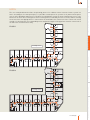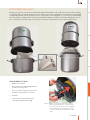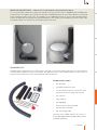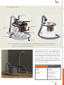
1
CENTRAL VACUUM CLEANER GUIDE FOR PROFESSIONALS
CENTRAL VACUUM CLEANER
GUIDE FOR PROFESSIONALS
Allaway Oy
www.Αllaway.com
We reserve the rights to make changes.
13991 MA0068EN Rev01 05.12
CENTRAL VACUUM CLEANER
GUIDE FOR PROFESSIONALS
COMPANY
PRODUCT DEVELOPMENT AND QUALITY
CONTENTS
COMPANY
3
PRODUCT DEVELOPMENT AND QUALITY
7
Measurement
9
Testing
12
DESIGNING THE SYSTEM
Designing
Fire regulations
DESIGNING THE SYSTEM
Case examples
PIPING SYSTEM
WALL INLETS
23
Semi-detached house
25
Terraced house
26
Flats
27
Hotel
28
29
Flow rate
30
Supporting the piping
31
Pipe packages
32
WALL INLETS
CLEANING EQUIPMENT AND ACCESSORIES CENTRAL UNITS
22
23
Product list: Allaway dust piping 40/44 mm
Pro catalogue
17
Detached house
PIPING SYSTEM
1
15
33
35
Cover assemblies
36
Optima mounting brackets
37
Installation of the Optima wall inlet
38
Product list: Optima and Classic wall inlets
39
Product list: RST wall inlets
41
Product list: sweep slots
42
COMPANY
44
Operation of the central unit
45
Filters47
Microfibre dust bags
48
Sealings and locks
49
LCD screen
50
C-series51
Designing
the Manta system
76
Location of the central unit
79
MANTA APC 3
80
Models81
Measurements and the required
installation space for the central unit
82
Technical data
82
CLEANING EQUIPMENT AND ACCESSORIES
83
Structure of the central unit
52
Wall bracket
53
Premium cleaning equipment set
84
The central unit's installation space
54
Product list: cleaning equipment
87
Installation of the central unit
55
Models57
Technical data and contents of the delivery
58
A-series59
Structure of the central unit
60
Installation of the central unit
62
Preseparator90
Expandable hose
91
Extension hose
91
Product list: accessories
92
Product list: filters
94
PRODUCT DEVELOPMENT AND QUALITY
Selecting the central unit
Manta75
DESIGNING THE SYSTEM
43
PIPING SYSTEM
CENTRAL UNITS
64
V-series65
Product lists
Piping system
33 - 34
Wall inlets
39 - 42
Models67
Dust bags and installation kits
49
Technical data and contents of the delivery
68
C-series
57 - 58
Duo69
A-series
63 - 64
V-series
67 - 68
DUO
74
Manta
81 - 82
Cleaning equipment
87 - 89
Accessories
92 - 93
Filters
94
Installation of the central unit
66
Installation of the central unit
70
Measurements and the required
installation space for the central unit
73
Models74
Technical data and contents of the delivery
74
Pro catalogue
2
CLEANING EQUIPMENT AND ACCESSORIES CENTRAL UNITS
Technical data and contents of the delivery
WALL INLETS
Models63
COMPANY
COMPANY
CLEANING EQUIPMENT AND ACCESSORIES CENTRAL UNITS
WALL INLETS
PIPING SYSTEM
DESIGNING THE SYSTEM
PRODUCT DEVELOPMENT AND QUALITY
COMPANY
Allaway Oy is a Finnish company which
manufactures Allaway central vacuum
cleaner systems and Ufox air humidifiers. It was established in 1982. Its factory
and offices are located in Jyväskylä, central Finland. The Allaway central vacuum
cleaner system has hundreds of thousands of users and it is the most popular
central vacuum cleaner brand in Europe.
Allaway offers durable high-quality prod-
3
Pro catalogue
ucts for home use and for more demanding professional use. Allaway develops,
manufactures, markets and sells highquality central vacuum cleaner systems
and air humidifiers. The company follows
and maintains the ISO 9001:2008 quality standard. All products are inspected
prior to delivery and everyone at Allaway
is committed to following the quality
requirements.
COMPANY
PRODUCT DEVELOPMENT AND QUALITY
DESIGNING THE SYSTEM
PIPING SYSTEM
WALL INLETS
Allaway strives to improve the quality of life. Everyday chores become easier, more comfortable
and quicker to finish. The main focus of Allaway's
operations is to improve indoor air quality and to
have a positive effect on people's health.
The company's operations are based on expertise
and professionalism and guided by environmental aspects and customer needs. This persistent,
customer-oriented quality thinking that has been
in place for decades earned Allaway the Lloyd's
Register Quality Assurance ISO 9001:2008 quality
certificate in 2002.
Pro catalogue
4
CLEANING EQUIPMENT AND ACCESSORIES CENTRAL UNITS
A HEALTHY HOME
PRODUCT DEVELOPMENT AND QUALITY
COMPANY
COMPANY
INTERNATIONAL ALLAWAY
Through its extensive network of importers,
Allaway delivers central vacuum cleaners to
Europe, Russia and the Middle East. Allaway's
reputation as a reliable and high-quality system provider constantly opens doors to new
market areas.
ECOLOGICAL FOOTPRINT
Figure 1. International Allaway.
CLEANING EQUIPMENT AND ACCESSORIES CENTRAL UNITS
The fact that it is not necessary to use dust bags in
our central vacuum cleaners reduces the amount
of waste in households. If a dust bag is used, due
to its large size it needs to be changed less often
than dust bags in ordinary vacuum cleaners.
When using a dust bag, the filter is changed only
when necessary.
GOOD QUALITY INDOOR AIR IS A FACTOR
FOR GOOD QUALITY LIFE!
In one day the average man consumes around
one litre of food and two litres of water and at
least 15,000 litres of air. Therefore, the meaning
of breathed air to health is unarguable. People
spend over 90% of their time indoors, so the air
that leaves the vacuum cleaner really matters.
WALL INLETS
PIPING SYSTEM
DESIGNING THE SYSTEM
What we leave behind matters to us. Therefore,
the focus of our quality process is on using materials that have the least environmental impact
in our products. Practice has shown that vacuum
cleaning with a central vacuum cleaner often
diminishes the need for vacuum cleaning as the
amount of dust is reduced. This also leads to a
decrease in energy consumption.
According to studies, bad quality indoor air is one
of the main factors contributing to the increase
in allergies. In Europe over 80 million people suffer from some type of allergy and the number is
constantly on the rise.
Each breathed litre of air includes millions of
small particles (size under 2.5 micrometres)
that penetrate deep into the lungs. The smaller
the particles are, the deeper into the body they
penetrate and the longer they stay in the body.
Figure 2. Allaway products are environmentally friendly.
5
Pro catalogue
In our opinion the best way to clean is to use a
central vacuum cleaner in which the vacuum
cleaner's exhaust air that contains small allergenic particles is directed out of the living
quarters.
COMPANY
Before vacuum cleaning
Central vacuum cleaner
DESIGNING THE SYSTEM
PRODUCT DEVELOPMENT AND QUALITY
Ordinary vacuum cleaner
During vacuum cleaning
Central vacuum cleaner
After vacuum cleaning
Ordinary vacuum cleaner
Central vacuum cleaner
Figure 3. The quality of indoor air is significantly improved by using central vacuum cleaner.
Pro catalogue
6
CLEANING EQUIPMENT AND ACCESSORIES CENTRAL UNITS
WALL INLETS
PIPING SYSTEM
Ordinary vacuum cleaner
COMPANY
PRODUCT DEVELOPMENT AND QUALITY
CLEANING EQUIPMENT AND ACCESSORIES CENTRAL UNITS
WALL INLETS
PIPING SYSTEM
DESIGNING THE SYSTEM
PRODUCT DEVELOPMENT AND QUALITY
PRODUCT DEVELOPMENT AND QUALITY
One of the factors behind Allaway's operations is the company's own, long-span
product development. Allaway product
development is carried out jointly by
designers and industrial designers. The
production of high-quality products is
guaranteed by the elegant design, carefully refined technique and usability. All
products go through a careful testing
process before being taken onto the market. Specific testing processes have been
developed for each product group.
7
Pro catalogue
The Allaway testing process has two
phases. In the first phase products are
tested by an independent, external testing
organization. The products that pass the
process are granted approval as a token for
the products' safety and functionality. In
the second phase every product is tested
once more by Allaway's own product development unit.
COMPANY
PRODUCT DEVELOPMENT AND QUALITY
DESIGNING THE SYSTEM
PIPING SYSTEM
WALL INLETS
Throughout the years, Allaway product development has
come up with numerous innovations. Thanks to these
innovations, Allaway has become a pioneer in the central
vacuum cleaner markets.
•
Piping that has been specifically developed to be
used in the central vacuum cleaner system.
•
Patented catchers in wall inlets.
•
C-series wall bracket which also enables
flush installation.
•
Connecting muff which has a precise adapter and
can therefore be utilised with pipes without muff.
•
Extension hose that can be used to prolong the
length of a handle-started suction hose.
•
Bespoke, ergonomically designed cleaning
equipment set.
•
Dust bag installation kit - Allaway is the only central
vacuum cleaner manufacturer that offers this as
an option.
•
Backflow valve that enables, among other things,
the use of one joint exhaust air duct for several
vacuum cleaners, for example in flats.
•
Steel-framed containers that are manufactured
with deep drawing technique for central units.
Pro catalogue
8
CLEANING EQUIPMENT AND ACCESSORIES CENTRAL UNITS
ALLAWAY INNOVATIONS
COMPANY
MEASUREMENT
PRODUCT DEVELOPMENT AND QUALITY
Measurement
During the product development phase, Allaway's
products undergo strict measurements.
MEASURING AND MARkING NOISE LEVELS
The noise power level LW remains the same
regardless of the distance of the listener/measuring microphone (in the example in Figure 1 the
noise power level remains at the standard 73dB
even though the noise pressure level changes
according to Figure 3).
A weighting filter is commonly used in measuring
the noise pressure level, for example A level. The
purpose of the A weighting is to match the measurement to the hearing sensitivity of the human
ear. The human ear can hear noises within the
frequency of 16-16000Hz. The attenuation curves
of the weighting filters are specified in, for example, the ISO standards.
Figure 1. Measurement is part of product development activities.
CLEANING EQUIPMENT AND ACCESSORIES CENTRAL UNITS
WALL INLETS
PIPING SYSTEM
DESIGNING THE SYSTEM
Measurements are carried out in an isolated,
semi-anechoic chamber based on the IEC 60704
standard. In the measurement laboratory the
pressure level of the noise is measured and
marked with an LP marking. It is possible to
use the pressure level to calculate other noise
quantities, such as the noise power level which
is marked with an LW marking. The unit for both
quantities is decibel [dB].
2M
Figure 2. Measurements are carried out in a semi-anechoic chamber that is isolated from all noise sources based on the standard IEC 60704.
During the measurement a normal cleaning situation is simulated.
9
Pro catalogue
COMPANY
Only a small part of an appliance’s mechanical
power turns into noise. In household appliances,
for example, the figure is less than 0.001%.
Let's compare the earlier mentioned noise quantities to heat that radiates from a fireplace. Heat
radiated from a fireplace feels hotter the closer a
person stands to the fireplace. The same applies
for the noise pressure level LP. Noise pressure
level is greater the closer the listener/measuring microphone is located to the source of noise
(Figure 3). From experience we know that the
closer we stand to a loudspeaker, the louder the
music sounds.
65
60
55
50
0,5
1
1,5
2
2,5
3
3,5
4
4,5
5
Distance of measuring microphone from source noise [m]
PIPING SYSTEM
Figure 3. Noise pressure level is greater the closer the noise
source is to the listener/measuring microphone.
THE ALLAWAY CENTRAL VACUUM CLEANER
SYSTEM WORkS WITHOUT DISTURBANCE
WITHIN THE POWER SUPPLY RANGE 207-244V.
WALL INLETS
All appliances in the Allaway central vacuum cleaner
system are designed to work without disturbance
within the power network voltage of 207-244V. The
voltage's quality is based on the standard SFS-EN
50160, which has been specified by Cenelec (European
Committee for Electrotechnical Standardization) and
the Finnish Electricity Association. The standard
specifies the effects of a divided electricity production
to the voltage of the low and middle voltage electricity
distribution network.
According to the standard, during each week 95%
of the 10-minute average values of the distribution
voltage's effective values must be within ±10% of the
rated voltage Un. Besides, in low voltage networks all
the 10-minute average values of the voltage's effective
values must be within Un +10%/-15%. When planning, the allowed voltage fluctuation in a low voltage
customer's point of coupling is often allowed to vary
between Un +6%/-10%, i.e. the low voltage customer's
voltage must be within the range 207–244V. (SFS 2008;
Laaksonen 2004)
Pro catalogue
10
CLEANING EQUIPMENT AND ACCESSORIES CENTRAL UNITS
70
PRODUCT DEVELOPMENT AND QUALITY
AN ExAMPLE OF THE NOISE
PRESSURE LEVEL
75
DESIGNING THE SYSTEM
The noise pressure level [dB]
CENTRAL UNIT MEASUREMENTS
Besides the noise pressure levels, the central units are measured for low pressure levels and
air power levels according to the EN standard 60312. The best solutions for accessories, such as
filters and dust bags, are chosen through absorbency tests, pressure difference measurements
and mechanical tests, for example.
100
2500
90
2250
80
2000
70
1750
60
50
40
30
Input power [W], Air power [W]
Vacuum [kPa], Efficiency [%], Speed [1000r/min]
DESIGNING THE SYSTEM
PRODUCT DEVELOPMENT AND QUALITY
COMPANY
MEASUREMENT
Vacuum
Air power
Input power
Efficiency
Flow rate
1500
1250
1000
750
20
500
10
250
0
0
0
5
10
15
20
25
30
35
40
45
50
55
Air Flow [dm³/s]
PIPING SYSTEM
Figure 4. An example of the turbine's characteristic curves and the measured quantities.
The optimal suction power of an Allaway central vacuum cleaner is guaranteed by simultaneously measuring the low pressure and the air volume in the central unit. The best cleaning result
is achieved at the highest point of the power curve. The measuring method used by Allaway is
shown in Figure 5.
600
35
Air Power max.
570W
Sealed vacuum.
28kPa
500
30
Vacuum when
air power is
maximum 19kPa
25
20
300
15
200
Vacuum
[kPa]
Air Power
[W]
WALL INLETS
400
Vacuum
[kPa]
Air Power
[W]
CLEANING EQUIPMENT AND ACCESSORIES CENTRAL UNITS
10
100
5
0
Air Flow max.
52 dm3/s
0
0
10
20
Air Flow
[dm3/s]
30
40
50
Figure 5. An example for calculating the air power of the turbine.
Air power = vacuum x air flow
To calculate the max. air power you need to know the vacuum and air flow levels at time the air
power is at its maximum (see the dotted lines in the figure). The maximum air power has been
calculated in the following example: 30 dm3/s x 19 kPa = 570W. In some cases the vacuum
cleaners' technicaltables only express the max. vacuum (usually closed vacuum) and max air
flow. It is not possible to calculate the air power with those values, as they are not comparable.
11
Pro catalogue
The air flow in the piping system has been tested
and optimised with different testing lines. The
prevention of blockages in the piping system
has been studied using numerous methods that
Allaway has developed by itself.
Allaway piping is designed for central vacuum
cleaner usage, so a stable and fast flow of air
(20-25 metres per second) is guaranteed. Allaway’s product development unit has been working together with plastic industry specialists in
developing the pipes' impact strength as optimal
as possible. The elbows and Y-branches have
special wearing surfaces in the places which are
exposed to wearing and impacts.
The muff of the pipes is produced with Allaway's
own muffing machine. The muff joint developed
by Allaway is reliable and significantly eases the
installation process - no glue is needed during
installation. Each pipe is checked for quality
before leaving the production line. The pipe must
be symmetrically round and its inner surface
must be smooth and clean. The pipe's round form
is guaranteed by the sufficient strength of the
pipe's walls.
Figure 7. The Allaway designed muff joint to the pipes is produced
with Allaway's own muffing machine.
Pro catalogue
12
PRODUCT DEVELOPMENT AND QUALITY
COMPANY
PIPING SYSTEM
DESIGNING THE SYSTEM
Figure 6. The life time tests for turbines are carried out in Allaway's own
laboratories.
The new alternative turbine motors and turbine
motors that are already in use are subjected to
test runs in which the turbine motor is rotated
in different on and off cycles until the turbine
motor's carbon brushes are fully worn out or
the turbine is otherwise damaged. After the test
run the electric motor turbines are examined
and the results are analysed to select the best
possible turbines.
PIPING SYSTEM
A powerful electric motor turbine is the main
element of the central unit. Service life time
tests are carried out at Allaway's own turbine
laboratory according to a test programme that
pushes the central unit significantly harder than
during normal use. The results of the testing
programme are analysed thoroughly, and the
turbines are constantly developed in cooperation
with the turbine manufacturers. The purpose
of the life time tests is to find the best turbine
models for the Allaway central units.
WALL INLETS
TURBINE TESTING
CLEANING EQUIPMENT AND ACCESSORIES CENTRAL UNITS
Testing
COMPANY
TESTINg
TESTING THE SYSTEM
PRODUCT DEVELOPMENT AND QUALITY
The Allaway central vacuum cleaner system is tested according to the testing methods of the standard
EN 60312. The tests help to estimate, for example,
durability of different types of cleaning equipment.
CLEANING EQUIPMENT
PIPING SYSTEM
DESIGNING THE SYSTEM
In a drop test the nozzle or the handle is put into
a test cylinder, which drops the piece to the bottom of the drum as it rotates. The number of drops
relates to a certain level of wear on the product.
The purpose of the test is to determine the nozzle
or the handle's ability to sustain impacts with walls
and thresholds in normal use.
The system's ability to remove dust is measured by
a dust pick-up test. The tested ground is covered
with test dust and the test nozzle is shifted with a
back and forth movement on the test ground five
times at a speed of 0.5 +/- 0.02 m/s. The measurement series is carried out three times and the
result shows the ability to remove dust in %.
Figure 8. Dust pick-up tests can be used to test the dust removal ability
of the different types of nozzles on different types of surfaces,
for example on hard floors or a range of different carpets.
Special attention has been paid to the usability and
ergonomics of the cleaning equipment. Our Premium cleaning equipment set has been developed
in collaboration with researchers at the Finnish
Institute of Occupational Health and usability experts at the JAMK University of Applied Sciences.
WALL INLETS
SERVICE
service
Takes care of ALL
CLEANING EQUIPMENT AND ACCESSORIES CENTRAL UNITS
www.allaway.com
Figure 9. In other countries the importer or the importer's servicenetwork is responsible for the Allaway products' guarantee
service.
In Finland, Allaway supports an extensive network
of qualified and authorised service dealers that
serve customers quickly and professionally. The
service dealers are responsible for the guarantee
service of the products manufactured by Allaway
Oy. In other countries the importer or the importer's service network is responsible for Allaway
products' guarantee service.
PACkAGING
Allaway Oy takes care of the utilisation of the packages it has delivered to the market according to
EU directives, laws on waste and the decisions and
regulations set by the government. The Environmental Register of Packaging PYR Ltd grants the
right to use its symbol to those companies that are
registered at PYR and that utilise packaging.
The packages are also suitable for recycling, and
this is indicated by a recycling mark in the packages.
Figure 10. The recycling mark shows that Allaway packages can be
recycled.
13
Pro catalogue
COMPANY
Protection class.
Class II = double insulated
Class I = protective earth
Class 0= basic insulation
IP code
IP = International protection
(ingress protection)
Serial number of the
machine to enable the
tracking of the central
units.
Ingress of solid foreign
particles.
X= no requirements
CE marking (in French Conformité Européene)
on the product shows that the manufacturer
guarantees that the product conforms to the
applicable EU directives and that the product has
undergone all the possible required inspections.
Accredited Notified Body
Low Voltage Directive,
LVD, 2006/95/EC
EMC Directive,
2004/108/EY
R&TTE-direktiivi
1999/5/EEC
EN-standards
Energy-related
The Waste Electrical and
Products Directive
Electronic Equipment Directive
(ErP Directive)
(WEEE Directive)
2009/125/EC
2002/96/EC
Restriction of Hazardous
Substances Directive
(RoHS), 2002/95/EC
Certificate of Compilance
Allaway Oy's certificate of
compilance to the product directives
Instructions manual
and technical file
Ingress of water.
4 = protected from splashing
water,
2 = protected from dripping
water
PIPING SYSTEM
Manufacturer of the
machine
In order to guarantee reliable CE marking for
Allaway central units, the central units are
subjected to testing during the design stages
by the Accredited Notified Bodies. In these
tests the units are tested for the important
safety requirements that they must comply
with before being safely introduced to the
EU market.
In the designing of the central units, the
directives that enhance the EU's goals for decreasing energy consumption, use of hazardous substances and unnecessary loading of
the environment are taken into consideration.
In the manual you will find the guarantee
of conformity with which Allaway declares
that its products are safe and conform to the
requirements of applicable directives.
Pro catalogue
14
WALL INLETS
Field for additional
information
CLEANING EQUIPMENT AND ACCESSORIES CENTRAL UNITS
Main voltage [V] and
frequency band [Hz] for
which the machine is
intended to be connected.
PRODUCT DEVELOPMENT AND QUALITY
The nominal power of the
central unit which it takes from
the electrical network:
PM = 0.5x(P1+P2), P1 minimum
power (suction is closed), P2
maximum power (suction is
fully opened)
Technical type
DESIGNING THE SYSTEM
ALLAWAY RATING PLATE
COMPANY
DESIgNINg THE SYSTEM
PRODUCT DEVELOPMENT AND QUALITY
DESIGNING THE SYSTEM
PIPING SYSTEM
DESIGNING THE SYSTEM
Y branch 45⁰
Sweep slot
CLEANING EQUIPMENT AND ACCESSORIES CENTRAL UNITS
WALL INLETS
Direct pipe
It is easy to design an Allaway central
vacuum cleaning unit. The system consists
of a central unit, piping, wall inlets and
cleaning equipment. All parts of the system work seamlessly together, ensuring a
long and reliable operating life. Allaway is
the only central vacuum cleaner manufacturer with its own integrated system.
15
Pro catalogue
The Allaway central vacuum cleaner system can be installed during the building
stages of the space, and retrofitting is also
easily accomplished. Home systems are
flat specific and can be used in detached
houses, terraced houses and flats. The
product selection offers a suitable system
for each requirement. Professional spaces
are often designed according to cleaning
practices or cleaning areas. Please see
Manta professional systems, page 75.
Central unit
Exhaust vent cap
WALL INLETS
Silencer
PIPING SYSTEM
Cleaning equipment set
DESIGNING THE SYSTEM
PRODUCT DEVELOPMENT AND QUALITY
Elbow in the piping system 90⁰
Pro catalogue
16
CLEANING EQUIPMENT AND ACCESSORIES CENTRAL UNITS
COMPANY
Wall inlet
COMPANY
Installation of the central unit
The location of the central unit is the basis for the
planning of the system. The type of central unit used
depends on its planned location, and the size of the
central unit is chosen according to the length of the
longest suction pipeline.
0,5 m
•
The choice of the central unit is dependent on
the installation space. Depending on the central
unit, the installation space can be located
indoors, in a utility space, storage space or in
some other secondary space. More information
is available on each series.
•
When installing the central unit on upper floors,
it is recommended that the ascent is maximum
4 metres. There can be several ascents if there
is a horizontal installation between the ascents
that is as long as the ascent.
•
There must be a socket in close proximity to
the central unit (10A slow blow plug fuse or 16A
automatic fuse).
Installation of the wall inlets
When the wall inlets are installed, attention is paid to
furnishings and the system must cover all premises
that need to be cleaned. The suction hose is 8, 9, 10 or
12 metres long according to the contents of the cleaning equipment set and the country. Please also note
the use of accessories like the preseparator or the
expandable hose. In order to use the preseparator,
the wall inlet can be installed near a fireplace. A wall
inlet is needed for the expandable hose in the hallway,
kitchen and next to the utility room, if there is one in
the building. A wall inlet in the utility room makes the
room easier to clean. The system can be supplemented by sweep slots that are installed in the support
structures of the furniture. Rubbish can be swept into
these sweep slots from, for example, the kitchen floor.
WALL INLETS
CLEANING EQUIPMENT AND ACCESSORIES CENTRAL UNITS
Please note with regard to the location of the central
unit:
Figure 1. Remember to install a socket right next to the central unit.
PIPING SYSTEM
DESIGNING THE SYSTEM
Designing
PRODUCT DEVELOPMENT AND QUALITY
Designing
Please note with regard to the installation of the
wall inlets:
Figure 2. We recommend that wall inlets are installed at the same level as
light switches.
17
Pro catalogue
•
Aesthetic aspect - it is recommended that the
wall inlets are installed at the same level as either
the wall sockets or the light switches. There are
several colour options for the Optima wall inlet
cover to match all possible styles. When choosing
the cover, it is recommended that all interior elements such as thickness, special walls and wall
effects are taken into account
•
Accessibility - in designing it is necessary to make
sure that the wall inlets are accessible in terms of
location of the furniture, fixed furniture and other
possible obstacles.
The pipes in the Allaway system fit together seamlessly and offer many opportunities for developing optimal designs for each project. Good planning enables
the optimisation of as straight a pipeline as possible.
Unnecessary bends and corners are avoided and
the number of the needed pipe parts is minimised.
Please note this when planning the system:
Figure 3. The longest pipeline is marked with orange. The central unit
is chosen by the longest pipeline.
•
The choice of the central unit is dependent on the
length of the longest pipeline, i.e. the distance
between the central unit and the wall inlet located
furthest away. (See Figure 3.)
•
Pipes must be supported evenly with pipe
clamp – the supporting distance must be
1200mm-1800 mm.
•
The pipes can run through all warm spaces, i.e.
the ceiling, base floor, partition walls and floor
casting.
•
Please note any possible structural obstacles.
•
The piping system can also be installed in cold
spaces, such as an attic. However, it must be
insulated with a 50 mm thick insulation layer.
•
The support structures of the cupboards and the
existing casings can be utilised in the planning/
installation of the piping systems.
•
Allaway dust pipes are installed without glue or
tape, except in casting installations in which the
points of connection of the pipes are secured
with tape.
•
The maximum individual rise in the piping is
4 metres and in Manta systems it can be 6
metres.
PLEASE NOTE!
In designing it is necessary to take note
of the fire regulations on, for instance,
compartmentation.
More information about fire regulations can be
found on page 21. Local fire officials will give
you more information about fire regulations.
Pro catalogue
18
PRODUCT DEVELOPMENT AND QUALITY
COMPANY
DESIGNING THE PIPING SYSTEM
DESIGNING THE SYSTEM
Ergonomics - wall inlets should be installed in
places that are ergonomically easy to reach.
Please note the location of doors and the direction that they open in, and the direction that the
wall inlets open in. If a wall inlet, for example, is
installed at the same level with the light switches,
it is advised that the installation is designed so
that the cover opens upwards. If the wall inlet is
installed close to the floor, on the same level as
the wall socket, it is advised that the installation
is designed so that the cover opens downwards.
PIPING SYSTEM
•
WALL INLETS
Practicality - There has to be enough wall inlets.
Please note that the wall inlets should be located
so that the vacuum cleaner is easy to use. We
recommend that the number of wall inlets is increased instead of prolonging the hose. A hose with
a maximum length of 8-10 metres is easy to use.
CLEANING EQUIPMENT AND ACCESSORIES CENTRAL UNITS
•
DESIGNING THE SYSTEM
PRODUCT DEVELOPMENT AND QUALITY
COMPANY
DESIgNINg
SILENCERS
Usually a silencer for exhaust air is installed at
the end of the exhaust pipe in the central vacuum
cleaner to reduce the level of noise. The place
for the silencer for exhaust air is located as near
to the end of the exhaust pipe as possible. See
Figure 5.
Figure 4. Allaway has two types of silencer. Above is the basic silencer
that reduces noise by approximately 14LpA (dB). Below
is the turbo silencer that reduces noise by approximately
20LpA (dB).
ExHAUST PIPE AND ExHAUST AIR
Please note the following with regard to the
location of the exhaust pipe and the exhaust air:
Ø 86
PIPING SYSTEM
Ø 44
WALL INLETS
•
The exhaust vent cap must be easily opened
in all seasons and weather conditions (for
example water or snow accumulation).
•
It is recommended that the exhaust pipe is located as far away as possible from windows,
vents, ventilation replacement air holes and
those areas of the garden where people want
to spend their time.
•
It is also possible to direct the exhaust air to
the ceiling. In that case, rain water must be
prevented from entering the piping by installing a leadthrough specially designed for this
purpose. A leadthrough to the ceiling must
be installed according to the manufacturer's
instructions.
•
If the exhaust pipe is more than 5 metres
long, the pipe must be expanded with a adjustment coupling muff 44/75/80 to a 75 or
80 mm diameter smooth ventilator duct or
sewer pipe. It is recommended that any possible expansion is located near the central
unit. An exhaust pipe with a larger diameter
efficiently silences the noise that is carried
outside. In Manta systems the diameter of
the exhaust air pipe depends on the number
and model of the central units.
32
0
Ø 125
CLEANING EQUIPMENT AND ACCESSORIES CENTRAL UNITS
The exhaust air silencer reduces the noise by
approximately 14LpA (dB). The turbo exhaust silencer reduces the noise by approximately 20LpA
(dB) with one turbo exhaust silencer and by approximately 30 LpA (dB) with two turbo exhaust
silencers (for example Manta systems).
Figure 5. The silencer should be located as close to the end of the
exhaust pipe as possible.
Information on the regulations, guidelines and orders on the exhaust pipe is available from the local
authorities.
Figure 6. An adjustment coupling muff 44/75/80 is used when the size
of the exhaust air pipe needs to be enlarged. The exhaust
air pipe can be enlarged with a smooth pipe with an inner
diameter of 75 mm if the length of the exhaust pipe exceeds
5 metres in length.
19
Pro catalogue
COMPANY
Figure 7. Air tightness is checked by closing all wall inlets or
mounting brackets by using pipe plugs (DPI-66 and DPI-70).
The operation of the system should be tested in
all wall inlets by sucking in some small particles
that fit into the inlet. If the particle does not move
from each inlet to the dust bag, there is a blockage in the piping. Locate and repair the blockage.
PRODUCT DEVELOPMENT AND QUALITY
The piping system must be checked for leaks
before the structures are closed. Air tightness
is checked by closing all wall inlets or mounting
brackets by using pipe plugs (See Figure 7). The
central unit is started by connecting the starting circuits with, for example, wire. The central
unit should be kept running for a maximum of
one minute, and if there is air coming out of the
exhaust pipe, the piping is leaking. Locate and
repair the leakage. Do not use the unit for more
than one minute when all wall inlets are closed,
because when the turbine receives no air, it will
overheat and may get damaged. Do not perform
the air tightness check with overpressure.
DESIGNING THE SYSTEM
TESTING THE SYSTEM
Figure 9. Allaway dust piping guarantees that there are no blockages in the system.
Pro catalogue
20
WALL INLETS
Figure 8. Due to the innovative structure, a muff joint is also achieved
when using connecting muff.
The connecting muff is easy install and no separate tools are needed. The Allaway connecting
muff is 10.2 cm long. When installing the connecting muff, ensure that the connecting muff
is installed in the right way in relation to the
flow direction of the piping. There are arrows
in the connecting muff to indicate the correct
flow direction.
CLEANING EQUIPMENT AND ACCESSORIES CENTRAL UNITS
It is possible to connect two muffless pipes with
connecting muff. Therefore, the muffless pipes
coming from the worksite can be utilised.
Thanks to its precise adapter, the connecting
muff is sealed without the need for any separate
piping seals.
PIPING SYSTEM
CONNECTING MUFF
LOW VOLTAGE LEAD
A 24V circuit is formed with a low voltage lead
between the wall inlet and the central unit (Manta
systems use a 12V circuit) In a system with several
wall inlets the wall inlets are coupled parallel (see
Figure 10). The leads can be connected both ways
to the wall inlet connectors and the low voltage
connector of the central unit. Several low voltage cables can also be connected to a separate
collector connection strip from where they are
connected to the low voltage connector. The low
voltage leads should run inside protective tubing.
Figure 10. Parallel coupling of the wall inlets.
The protective tubing is particularly crucial when
installing the piping to molding, masonry, or other
places where changing the leads after potential
damage is difficult. In other cases, such as when
installing the leads to hung ceilings, the lead can
be attached to the dust pipe with cable ties. It is
recommended that the leads follow the lines of
the body piping, but they can also be led through
the easiest possible route. Low voltage leads to
separate central units must not be connected to
each other. The leads must always be extended
and branched very carefully.
Figure 11. Allaway pipe clamp supports the pipes. Low voltage leads
that run beside the piping have been accounted for in the
pipe clamps.
CLEANING EQUIPMENT AND ACCESSORIES CENTRAL UNITS
OPERATION INDICATOR
The operation indicator follows the low voltage
circuit of the central vacuum cleaner system to
detect when the central unit is on and transmits
potential-free contact information to the leads
A-B of the indicator. The information can be used
to control the ventilator, for example. With the
help of the operation indicator, it is possible to
prevent the formation of excessive low pressure
and to reduce the air flow coming in from the
structures (for example through the funnel). The
device is intended only to be used together with
Allaway central vacuum cleaners (but not with
the Manta, Sonis or CX central units).
WALL INLETS
PIPING SYSTEM
DESIGNING THE SYSTEM
PRODUCT DEVELOPMENT AND QUALITY
COMPANY
DESIgNINg
Figure 12. When installing the piping in molding or masonry, protective tubing is extremely important.
Figure 13. Operation indicator provides potential-free
contact information.
21
Pro catalogue
Ventilation
machine
Figure 14. An example of how the operation indicator works.
ExPANSION jOINT
In special cases, for example in moulded structures, when the expansion joint is crossed, the
dust piping must be isolated with 20-25 mm
thick foam rubber for a length of one metre. This
prevents the pipe from breaking at the expansion
joint.
Figure 16. In moulded structures the expansion joints must be isolated with foam rubber.
Pro catalogue
22
PRODUCT DEVELOPMENT AND QUALITY
COMPANY
Use approved fire barrier products, for example
firestop collars or masses, in leadthroughs of
compartmentation structures. If necessary,
ensure that the protection and casing class of
the central unit correspond to the requirements
of its location and the related equipment. More
information is available from the local officials.
DESIGNING THE SYSTEM
Figure 15. A Fire wall
B Insulation with non-flammable material
C Dust pipe 44 mm-diameter
D Approved fire barrier product
E Light partition
In detached houses, the garage and boiler room
are usually separate fire compartments Pipes
may be led through compartmentation structures, assuming that the leadthrough does not
significantly reduce the fireproof properties of
the structures.
PIPING SYSTEM
LEADTHROUGHS IN
COMPARTMENTATION STRUCTURES
WALL INLETS
When designing and installing a central vacuum
cleaner system, the guidelines and regulations of
the local fire officials must be followed. Special
attention must be paid to the compartmentation
and the regulations on the exits in terms of the
permitted materials. More information is available from the local fire officials.
CLEANING EQUIPMENT AND ACCESSORIES CENTRAL UNITS
FIRE REGULATIONS
Case examples
ExPLANATION FOR THE MARkINGS
Piping system
Pipe up
Central unit
Option
Exhaust pipe
Sweep slot
Silencer for exhaust air
Pipe down
Central vacuum cleaner systems are designed for and installed in up to 80% of new detached houses built
in Finland. The system can also be installed in prefabricated detached houses. In the example house the
wall inlets have been installed so that a 10-metre hose is long enough for vacuum cleaning. The exhaust
pipe is located at the end of the house, as far away as possible from the garden.
PIPING SYSTEM
DOWNSTAIRS
WALL INLETS
CLEANING EQUIPMENT AND ACCESSORIES CENTRAL UNITS
Wall inlet
DETACHED HOUSE
DESIGNING THE SYSTEM
PRODUCT DEVELOPMENT AND QUALITY
COMPANY
CASE ExAMPLES
23
Pro catalogue
COMPANY
PRODUCT DEVELOPMENT AND QUALITY
ACCESSORIES:
•
C30
•
Sweep slot
•
Wall bracket
•
•
22 m pipe
expandable hose (length 1 m,
but expands to 4 m → can be stored in
the cutlery drawer)
•
Elbow 90⁰ 6 pcs
•
Elbow 45⁰ 3 pcs
•
Wall inlet 3 pcs
•
Branch 2 pcs
•
Cleaning equipment set 9-10 m
•
Silencer
In log cabins, the design of the central
vacuum cleaner system is in some parts different to the design of systems in detached
houses. In log homes, the wall inlets can be
best installed in light partition walls, masonry walls or the support structure of fixed
furniture. Guidelines and instructions on the
design process of the systems for log cabins
is available at www.Αllaway.com
Pro catalogue
24
CLEANING EQUIPMENT AND ACCESSORIES CENTRAL UNITS
ACCESSORIES
WALL INLETS
PIPING SYSTEM
DESIGNING THE SYSTEM
UPSTAIRS
SEMI-DETACHED HOUSE
In semi-detached houses the central vacuum cleaner system is designed the same way as in detached
houses, specifically for each dwelling, but the dwellings can also use a joint exhaust duct. In this case the
central unit must come from the C-series. Common fire regulations must be followed when designing the
blow-out.
PIPING SYSTEM
DESIGNING THE SYSTEM
PRODUCT DEVELOPMENT AND QUALITY
COMPANY
CASE ExAMPLES
CLEANING EQUIPMENT AND ACCESSORIES CENTRAL UNITS
WALL INLETS
ACCESSORIES:
25
•
Central unit C30
•
24m pipe
•
Elbow 90⁰ 5 pcs
•
Elbow 45⁰ 4 pcs
•
Branch 1 pcs
•
Wall inlet 2 pcs
•
Silencer for exhaust air
•
Cleaning equipment set 10m
Pro catalogue
COMPANY
The Allaway central vacuum cleaner is easy to install in a terraced house. In terraced houses the system is
designed specifically for each dwelling.
UPSTAIRS
DESIGNING THE SYSTEM
DOWNSTAIRS
PRODUCT DEVELOPMENT AND QUALITY
TERRACED HOUSE
PIPING SYSTEM
UPSTAIRS
ACCESSORIES:
•
120m pipe
•
Elbow 90⁰ 40 pcs
•
Elbow 45⁰ 16 pcs
•
Branch 8 pcs
•
Exhaust vent cap 8 pcs
•
Silencer for exhaust air 8 pcs
•
Wall inlet 16 pcs
•
C-series wall bracket 8 pcs
•
C30 8 pcs or DUO 8 pcs
•
Cleaning equipment set 8 pcs
Pro catalogue
26
CLEANING EQUIPMENT AND ACCESSORIES CENTRAL UNITS
WALL INLETS
DOWNSTAIRS
FLATS
In flats, the central vacuum cleaner systems are designed according to the same principles as systems in
detached houses, for example. It is possible to design a system that is dwelling-specific. The exhaust duct
can be dwelling-specific or all flats can use one joint exhaust duct. In that case a central unit from C-series
is needed. It has a built-in return valve on the exhaust side. Common fire regulations and instructions must
be followed when designing the blow-out.
CLEANING EQUIPMENT AND ACCESSORIES CENTRAL UNITS
WALL INLETS
PIPING SYSTEM
DESIGNING THE SYSTEM
PRODUCT DEVELOPMENT AND QUALITY
COMPANY
CASE ExAMPLES
27
Pro catalogue
COMPANY
The case example below describes the planning process for a Manta central vacuum cleaner system in a
hotel. According to the same principles it is possible to make plans for systems in all professional spaces
such as office buildings and nurseries. The basis for designing a system for many simultaneous users is the
division of the areas into cleaning areas. Each cleaning area is cleaned by one user at a time, and all cleaning
areas have their own piping which is connected to the manifold in the central unit. One central unit can be
used by 1-3 simultaneous users depending on the maximum lengths of the pipelines from the central unit to
the wall inlet located furthest away.
DESIGNING THE SYSTEM
FLOOR 1
PRODUCT DEVELOPMENT AND QUALITY
HOTEL
PIPING SYSTEM
Cleaning area 1
Cleaning area 2
Pro catalogue
28
CLEANING EQUIPMENT AND ACCESSORIES CENTRAL UNITS
WALL INLETS
FLOOR 2
COMPANY
PIPINg SYSTEM
CLEANING EQUIPMENT AND ACCESSORIES CENTRAL UNITS
WALL INLETS
PIPING SYSTEM
DESIGNING THE SYSTEM
PRODUCT DEVELOPMENT AND QUALITY
PIPING SYSTEM
Allaway dust piping offers ready-made
parts. After the easy design process, the
piping is easily assembled without any
need for glue or special tools. Optimally
dimensioned elbow pieces, smooth and
durable inner pipe surfaces, optimal pipe
diameter and tight connections ensure that
the Allaway system has the best possible
flowing qualities on the market.
The pipes fit together seamlessly. There
are several options for different types of
installation projects.
29
Pro catalogue
The inner surface of the pipes is extremely
smooth. All elbows are rounded and places
that are exposed to wear are strengthened.
The piping system can be installed in
houses of various ages and styles in separate casings on ceilings, cupboards or stair
structures. Extending the piping system
later on is just as easy.
The optimal pipe diameter, 44 mm, helps all
rubbish flow effectively and guarantees the
necessary dust flow velocity of 25 m/s.
•
A 44 mm pipe is suitable for all walls with
a structure made of wood, blocks or bricks
and for different types of ceiling or floor
structures, also in prefabricated houses.
•
It is easy to cut the pipe into desired lenghts.
Connecting muff can be used to connect
the muffless pipes that have been cut. This
minimises the loss of pipe.
•
No glue or special tools are needed
in installation.
•
The material of the pipes is
extremely durable.
•
The functional elbow pieces guarantee that
rubbish will not cause any blockages.
•
Winter installation is also possible.
Please note the possibility of thermal
expansion as the temperature changes!
•
There is no loss of suction power over
the years.
•
Solid and smooth inner surface - rubbish
won't collect in places and cause blockages.
•
Strengthened elbow pieces guarantee a long
service life as they won't wear out.
•
Piping is made of environmentally friendly
recyclable material.
Figure 1. 44 mm-diameter piping guarantees optimal flow properties.
The inner surface of Allaway
pipes is extremely smooth and
durable.
Optimally dimensioned elbow
pieces guarantee that rubbish
and dust flow freely in the
piping. All elbows are rounded
and places that are exposed to
wear are strengthened.
Tight seals guarantee that the
pipes fit together seamlessly.
There are several options for
different types of installation
projects.
Pro catalogue
30
PRODUCT DEVELOPMENT AND QUALITY
COMPANY
•
DESIGNING THE SYSTEM
ADVANTAGES OF THE 44 MMDIAMETER PIPING
PIPING SYSTEM
Allaway central vacuum cleaner systems use
their own piping system that is specially designed
for Allaway systems. The piping system is the
result of a lengthy and thorough product development process. The Allaway dust piping system's
outer diameter is 44 mm and the inner diameter
is 40 mm. The piping is studied to be optimal in
its flowing qualities. Flow technically optimally
designed and dimensioned elbow pieces, smooth
and durable pipes' inner surfaces, optimal pipe
diameter and tight connections ensure the
best possible flow qualities and blockage-free
dust piping.
ø 44 mm
WALL INLETS
Flow rate
CLEANING EQUIPMENT AND ACCESSORIES CENTRAL UNITS
ALLAWAY CENTRAL
VACUUM CLEANER
Supporting the piping
A pipe clamp developed by Allaway enables several
different ways for providing support. When supporting the piping, only use the Allaway pipe clamp and
install the pipe clamp so that the pipe can move
freely axially (in the longitudinal direction). Support
the piping in a manner that allows axial thermal
expansion and contraction (muff joints in particular
should not be subject to extension strain as the piping
contracts.) Only install the pipe clamps in stretches
of pipe without bends, and at a sufficient distance
from the muff joints to enable thermal expansion
and contraction. The thermal expansion coefficient
is approximately 0.1mm/m/°C). In order to allow for
the movement of the pipe, only one pipe clamp is
allowed near an elbow piece, as shown in the picture.
The pipe clamp on the other side of the elbow piece
must be at least 70cm from the elbow piece. No
pipe clamps are installed on direct stretches of pipe
shorter than 70cm.
DESIGNING THE SYSTEM
PRODUCT DEVELOPMENT AND QUALITY
COMPANY
SUPPORTINg THE PIPINg
WALL INLETS
Figure 2. Pipe clamps can be attached when the pipe is in place.
There is enough space for the screwdriver and the
screw to manoeuvre round the pipe.
Figure 4. Enables attachment with screws at the centre of the
support.
CLEANING EQUIPMENT AND ACCESSORIES CENTRAL UNITS
PIPING SYSTEM
SUPPORTING METHODS
Figure 3. The pipe clamp can be attached by its sides with long
screws. The pipe is not able to slide in the support as it
locks the pipe in its place.
Figure 5. Pipe clamp attached with a screw at the centre. This
installation method also enables the pipe to move in
the longitudinal direction during thermal expansion, for
example.
31
Pro catalogue
COMPANY
DESIGNING THE SYSTEM
PRODUCT DEVELOPMENT AND QUALITY
PIPE PACKAGES
Product 80331
Quantity
Product 80381
Quantity
Wall inlet Optima 100
3
1
1.2 m pipe
14
4
0.6 m pipe
8
3
Sealing yellow
39
15
Elbow 45°
6
2
Elbow 90°
7
2
Y-branch
2
1
Metal strip
6
1
Exhaust valve
1
Start wire 30 m
1
Example
content
Star wire 10 m
WALL INLETS
PPL additional
pipe package
1
Pipe clip 3 in set
1
Exhaust pipe
1
Pro catalogue
32
CLEANING EQUIPMENT AND ACCESSORIES CENTRAL UNITS
PPk pipe
package
PIPING SYSTEM
Figure 6. Allaway piping parts are sold as single components and in basic and additional pipe packages. Below is an example of
one package. The contents of the package vary depending on the country.
COMPANY
PRODUCT LIST: ALLAwAY DUST PIPINg 40/44 MM
~5
~146
~164
Ø
R95
Ø44
~47
~144
R9
5
Ø ~50
Elbow 90⁰
Product code 80526.
Inner diameter Ø 40 mm.
Outer diameter Ø 44 mm.
Muff outer diameter Ø 50 mm.
Ø 44
Ø ~50
⁰
DESIGNING THE SYSTEM
45
Branch 45⁰
Product code 80527.
Inner diameter Ø 40 mm.
Outer diameter Ø 44 mm.
Muff outer diameter Ø 50 mm.
~215
60
R1
Ø 44
Ø 50
Ø 50
~2400
Ø 50
~1200
Ø 50
Ø 40
Ø 40
~600
Ø 40
~300
Ø 40
PIPING SYSTEM
WALL INLETS
Ø 44
Elbow 15⁰
Product code 80528.
Inner diameter Ø 40 mm.
Outer diameter Ø 44 mm.
Muff outer diameter Ø 50 mm.
~168
R95
~162
Ø ~50
~15
Pipe 0.3 m
PP 80543 .
Inner diameter Ø 40 mm.
Outer diameter Ø 44 mm.
Muff outer diameter Ø 50 mm.
Pipe 0.6 m
PP 80542 . PVC 80517.
Inner diameter Ø 40 mm.
Outer diameter Ø 44 mm.
Muff outer diameter Ø 50 mm.
Pipe 1.2 m
PP 80541 . PVC 80516.
Inner diameter Ø 40 mm.
Outer diameter Ø 44 mm.
Muff outer diameter Ø 50 mm.
Pipe 2.4 m
PP 80540 . PVC 80515.
Inner diameter Ø 40 mm.
Outer diameter Ø 44 mm.
Muff outer diameter Ø 50 mm.
Pipe tab DBI-70 44m
Product code 80521
100
33
Pro catalogue
Connecting muff
Product code 80295.
Ø 50
Ø 40
CLEANING EQUIPMENT AND ACCESSORIES CENTRAL UNITS
Elbow 45⁰
Product code 80525.
Inner diameter Ø 40 mm.
Outer diameter Ø 44 mm.
Muff outer diameter Ø 50 mm.
0
PRODUCT DEVELOPMENT AND QUALITY
Product list: Allaway dust piping 40/44 mm
COMPANY
18.5
68
~10 m
PRODUCT DEVELOPMENT AND QUALITY
60
Ø 43.5
Pipe clamp 25 pcs.
Product code 80294.
Pipe clamp 3 pcs.
Product code 80293.
Low voltage lead 10 m Product code 80940.
Low voltage lead 20 m Product code 80945.
Low voltage lead 30 m Product code 80950.
Low voltage lead 100 m Product code 80954.
2 x 0.35 mm2
15.5
Ø ~50
DESIGNING THE SYSTEM
Pipe sealing 15 pcs
Product code 15170.
16
OI-indicator
Product code 80805.
35
66.7
15.5
PIPING SYSTEM
Ø 86
Ø 80
Ø 75
Ø 44
Ø ~50
Adjustment coupling muff 41/44
Product code 80933.
Converter coupling muff 44/50
Product code 80932.
Adjustment coupling muff 44/75/80
Product code 80934.
~66
~323
155
~167
WALL INLETS
~265
Exhaust vent cap
Product code 80792.
19
Low pressure meter
Product code 80984.
Pro catalogue
34
CLEANING EQUIPMENT AND ACCESSORIES CENTRAL UNITS
630
Turbo exhaust silencer
(includes blow-out grating)
Product code 80791.
Ø 125
22
140
Ø 44
700
140
Ø 100
Ø 86
Silencer for exhaust air
Product code 80965.
COMPANY
wALL INLETS
CLEANING EQUIPMENT AND ACCESSORIES CENTRAL UNITS
WALL INLETS
PIPING SYSTEM
DESIGNING THE SYSTEM
PRODUCT DEVELOPMENT AND QUALITY
WALL INLETS
Figure 1. By using a mounting bracket, you can install the wall inlet cover so that it opens in a desired direction.
Allaway wall inlets are designed to fit
perfectly to the Allaway central vacuum
cleaner system's piping and cleaning
equipment. The Optima wall inlet boasts
many innovative properties that have
helped to enhance the suction power and
the usability of the vacuum cleaner.
35
Pro catalogue
COMPANY
PRODUCT DEVELOPMENT AND QUALITY
Cover assemblies
Cover seals ensure that the
cover is not leaking while other
wall inlets are used for vacuum
cleaning.
In suction hose assemblies
equipped with a handle starter
you can start and stop cleaning
simply by using the handle.
The cover is equipped with a
steel spring and it is easy to
open and close. You can lock
the cover by fully opening it
upwards. When the suction
muff clicks, this indicates that
the muff is securely attached
to the wall inlet. The steel
spring in the cover ensures the
airtightness of the wall inlets.
DESIGNING THE SYSTEM
Suction hose muffs become
tightly sealed on both sides of
the inlet and keep the suction
hose tightly attached to the
inlet. It is easy to release the
hose by lightly pressing the
suction hose muff's lock.
Figure 4. There are sealing grooves behind the
Figure 2. Allaway wall inlets are equipped Figure 3. The starting circuit operates at a voltage
wall inlet. These can be shortened
with patented catchers that
of approximately 24V. The low voltage lead
according to the thickness of the wall
prevent large items such as
is attached to each wall inlet and to the
material. If the wall material is thicker,
children's building blocks from
sweep slot connectors, where installed.
it is possible to use a separate extension
entering the suction pipe system.
in between the mounting bracket and the
cover assembly.
Pro catalogue
36
CLEANING EQUIPMENT AND ACCESSORIES CENTRAL UNITS
WALL INLETS
PIPING SYSTEM
Allaway wall inlets are equipped
with patented catchers that
prevent large items such as
children's building blocks
from entering the suction
pipe system. All rubbish and
other items that penetrate the
catchers travel all the way to
the central unit’s dust bag.
Optima mounting bracket
Protective plug,
used also as a muff for 16 mm
protective tubing
Cuttable attachment
brackets
By using several attachment
holes the cover assembly is
attached straight
Enables the use of a 20 mm
protective tubing in low voltage
leading
There are numerous
attachment options to match
the needs of different types of
installations.
CLEANING EQUIPMENT AND ACCESSORIES CENTRAL UNITS
WALL INLETS
PIPING SYSTEM
DESIGNING THE SYSTEM
PRODUCT DEVELOPMENT AND QUALITY
COMPANY
OPTIMA MOUNTINg bRACkET
Figure 5. The Optima mounting bracket is easy and quick to install in all wall materials as its structure enables several possibilities for installation. Due to
the symmetry of the mounting bracket, the cover can be opened in any
direction.
37
Pro catalogue
Figure 6. The sharpest elbow of the entire piping system is
directly behind the wall inlet. It prevents long items
such as pencils from entering the piping system.
Wall inlets are normally installed in partition walls
of wood or metal structures, in cast or masoned
partition walls of bricks and in cupboards and support structures. When installing in a concrete cast
COMPANY
(floor), inside or in a groove of a block or a brick
wall, the connections must be taped and the pipes
must be attached so that they cannot move. Low
voltage leads should run inside protective tubing in
cast structures.
SLAB WALL INSTALLATION
Figure 7. When installing a wall inlet to a brick wall, the bricks must be
split or a groove must be made for the dust pipe. A low voltage
lead runs to the wall inlet inside protective tubing. If the wall
is coated, it can be completely masoned. For the installation of
the pipe, a groove is sawn into the wall on the side of the wall
to be coated. The space for the pipe can also be left during
masonry. The dust pipe, low voltage lead, protective tubing,
mounting bracket, and the protective cover are installed in the
finished groove. Use filler to fill the groove up to the level of
the wall surface.
Figure 9. When installing in a slab wall, the mounting bracket is
installed to the frame of the wall with a nail or a screw. The
best possible support is achieved by installing the mounting
bracket on both sides using a 500 mm additional frame. Slab
wall installation is also possible without the mounting bracket.
INSTALLATION THROUGH A WALL
SURFACE INSTALLATION
Figure 8. When a dust pipe is connected to the wall inlet on the other
side of the partition wall, a hole with a diameter of 50 mm is
drilled through the wall for the installation of the wall inlet.
The wall inlet's elbow coupling is inserted into the end of the
dust pipe. If the wall inlet is installed through thick walls,
several extensions can be used successively. The length of the
extension is 13 cm. Wall inlet extensions are used in installations through thick walls.
Figure 10. Box for surface installation (accessory) is used in the sur
face installation of the piping. The box for surface installa
tion is mounted to the wall. The elbow coupling is attached to
the dust pipe and the dust pipe is pushed up to the sharp 90º
angle of the elbow coupling. Dust pipe is inserted into the box.
Low voltage leads are attached to the cover assembly and
the cover assembly is installed to the box.
Pro catalogue
38
CLEANING EQUIPMENT AND ACCESSORIES CENTRAL UNITS
WALL INLETS
PIPING SYSTEM
DESIGNING THE SYSTEM
BRICk WALL INSTALLATION
PRODUCT DEVELOPMENT AND QUALITY
Installation of the Optima wall inlet
COMPANY
PRODUCT LIST: OPTIMA AND CLASSIC wALL INLETS
PRODUCT DEVELOPMENT AND QUALITY
Product list: Optima and Classic wall inlets
Optima wall inlet, white
Product code 80160.
The package includes the mounting
bracket, protective cover, white Optima
cover assembly.
90
Wall inlet Allaway Optima: wall inlet,
inlet elbow, extension piece
Product code 80194.
44
Optima cover assembly
Antique brass. Product 80186.
Graffiti. Product 80185.
Black. Product 80183.
Silver. Product 80184.
White. Product 80178.
90
DESIGNING THE SYSTEM
90
90
~92
50
Optima mounting bracket
Product code 80223.
~171
The Optima mounting bracket is easy and
quick to install in all wall
materials.
PIPING SYSTEM
~164
Ø 73
7.5
Ø 46.3
124
WALL INLETS
128
~91
77
Extension
Product code 80214.
When the coupling muff of the cover
assembly does not reach to the elbow
coupling, an extension is used. The
length of the extension is 13 cm.
Wall inlet elbow coupling
Product code 80122.
The classic wall inlet is always
followed by elbow coupling to prevent
pencils and other long pieces from
entering to the pipe system.
Box for surface installation
Product code 80222.
~90
CLEANING EQUIPMENT AND ACCESSORIES CENTRAL UNITS
54
Protective cover, round
Product code 80224.
Pipe tab DBI-66
Product code 80522.
39
Pro catalogue
COMPANY
PRODUCT DEVELOPMENT AND QUALITY
Wall inlet surface installation
Optima
Product code 80164.
104
69
DESIGNING THE SYSTEM
116
Classic wall inlet.
42
Inlet white plastic; reed complete. 80157.
Inlet white plastic; no reed complete. 80158.
104
Inlet white plastic; microswitch complete. 80150.
Inlet cover white; plastic reed. 80176.
Inlet cover white; no reed. 80196.
Inlet cover white; plastic microswitch. 80175.
97
134
20
60
119
83
Classic frame (raised installation)
Product code 80195.
Outer measurements from the front:
13.3 cm x 9.6 cm. Inner measurements
from the front: 10.5 cm x 7.0 cm
PIPING SYSTEM
132
15
Classic frame (flush installation)
Product code 80205.
Outer measurements from the front:
13.5 cm x 9.8 cm. Inner measurements
from the front: 10.56 cm x 7.0 cm
Protective cover for flush installation
Product code 80216.
Protective cover for raised installation
Product code 80215.
WALL INLETS
95
15
93
Socket for surface installation
plastic, white
Product code 80219.
131
58
54
121
74
Mounting bracket
Product code 11031.
Mounting bracket + inlet elbow
Product code 80173.
Pro catalogue
40
CLEANING EQUIPMENT AND ACCESSORIES CENTRAL UNITS
92
Wall inlet DUO
Product code 80170.
You can use Duo from one wall inlet
or add dust piping to the wall inlet
and then install several wall inlets.
COMPANY
PRODUCT LIST: RST wALL INLETS
Product list: RST wall inlets
PRODUCT DEVELOPMENT AND QUALITY
RST wall inlets are only suitable for use with Allaway handle-started cleaning equipment or professional
cleaning equipment equipped with Reed muffs.
Stainless steel inlet frame lifted
installation chrome
Product code 80277.
Stainless steel inlet frame lifted
installation white
Product code 80278.
28.5
160
125
157
62
stainless steel chrome. 80218.
Sockets include inlet frames.
122
DESIGNING THE SYSTEM
Socket for surface installation
Socket for surface installation
stainless steel white. 80220.
Sockets include inlet frames.
95
Installation cover stainless steel
chrome
Product code 80274.
130
52
Installation cover stainless steel white
Product code 80281.
52
PIPING SYSTEM
130
95
Wall inlet stainless steel complete
reeds on/off chrome
Product code 80259.
124
95
130
Installation cover stainless steel
chrome with lock
Product code 80273.
Installation cover stainless steel white
with lock Product code 80282.
54
124
130
WALL INLETS
CLEANING EQUIPMENT AND ACCESSORIES CENTRAL UNITS
Wall inlet stainless steel complete
reeds on/off chrome with lock
Product code 80258.
95
54
Figure 11. The stylish and durable stainless steel inlets can be surface mounted using separate surface mounting equipment.
Mounting is also possible at the floor level.
41
Pro catalogue
COMPANY
~217
PRODUCT DEVELOPMENT AND QUALITY
Product list: sweep slots
Sweep slot, white
Product code 81009.
~99
DESIGNING THE SYSTEM
54
Sweep slot, black
Product code 81034.
Sweep slot RST Covering panel
Product code 80289.
3
300
89
~250
Allaway sweep slot Europe,
white
Product code 81234
Allaway sweep slot Europe,
grey/silver
Product code 81235.
Figure 12. The sweep slot is easy to install to the support structures of kitchen furniture, for example. The sweep slot turns on automati
cally when the slot is opened. It is particularly handy in the kitchen and in other spaces that need regular cleaning.
Pro catalogue
42
CLEANING EQUIPMENT AND ACCESSORIES CENTRAL UNITS
WALL INLETS
89
Suitable for products 81009
and 81034.
PIPING SYSTEM
61
255
COMPANY
CENTRAL UNITS
CLEANING EQUIPMENT AND ACCESSORIES CENTRAL UNITS
WALL INLETS
PIPING SYSTEM
DESIGNING THE SYSTEM
PRODUCT DEVELOPMENT AND QUALITY
CENTRAL UNITS
Allaway central units are suitable for every
size of home and every type of installation space. A-series is a traditional central unit line that can be installed in warm
storage spaces or utility rooms. C-series
can be installed indoors, in places such
as inside the cleaning cupboard or in the
bathroom. Allaway's tiny Duo is especially
well-suited for installation in flats and ter-
43
Pro catalogue
raced houses, in holiday homes or even
in motor homes and boats. Due to its size
and shape it can be placed almost anywhere. Seamless steel frames ensure a
non-resonant operating noise, durable and
fire-safe structure and long lifespan for the
C and A-series. As steel has a long lifespan and it is recyclable, it is an ecological
frame material.
Feature
C-series
COMPANY
A-series
V-series
Duo
DESIGNING THE SYSTEM
Several factors, such as the location of the central unit and the specific features of the vacuum cleaned space
affect the selection of the central unit type. The selection of the model is dependent on the length of the dust
piping system, i.e. the distance between the central unit and the wall inlet located furthest away. The central
unit model's name indicates the maximum distance in a numerical value, for example A 30 A rough estimate
is that the A 30 model, for example, is suitable for a space in which the distance from the central unit to the
wall inlet furthest away is under 30 metres.
PRODUCT DEVELOPMENT AND QUALITY
Selecting the central unit
Manta
For domestic use
PIPING SYSTEM
For professional use
Metal-framed
Metal/Plastic-framed
Plastic-framed
LCD screen
(C40 LCD)
(A40 LCD)
(Not C40 LCD)
(Not A40 LCD)
Hidden pipe installation is possible
Possibility to use either with or without
the dust bag (accessory)
Energy efficient
Possibility to use
several wall inlets simultaneously
(more than one cleaner)
(Necessary)
(C40)
(A40)
(Not 3000)
Special installation sites: leisure venues, boats,
buses, mobile homes
Installation of exhaust air is possible in the same
exhaust duct (for example in flats)
Backflow valve (enables, among other things,
the use of one joint exhaust air duct)
Overheat protector
Overload protector
Pro catalogue
44
CLEANING EQUIPMENT AND ACCESSORIES CENTRAL UNITS
Splash proof
WALL INLETS
Installation in a cupboard is possible
Operation of the central unit
PIPING SYSTEM
DESIGNING THE SYSTEM
PRODUCT DEVELOPMENT AND QUALITY
COMPANY
OPERATION Of THE CENTRAL UNIT
DUST FLOW
TURBINE
Regardless of their type, the Allaway central
units all share a similar structure. The central
units consist of a turbine, dust guide, filter, dust
container and a protective cover. Each central
unit type comes with special features specifically designed for each model. The figure below
shows the dust flow in a central unit.
The turbine is firmly attached from above and below
to the turbine housing that protects the turbine.
High quality sealing reduces the vibration.
The dust guide is located in the central casing of the
central unit. It guides the dust tangentially from the
inlet coupling down to the central container by its
edges. The air guide protects the filter and prolongs
its lifespan.
Noise reducing
protective cover
Exhaust air out
Protective housing
for the turbine
Turbine
Vibration silencers
Control card in stand-by
mode, consumption less
than 0.50W (in LCD units
1.5W)
CLEANING EQUIPMENT AND ACCESSORIES CENTRAL UNITS
WALL INLETS
Suction air's inlet
and dust guide
45
Pro catalogue
COMPANY
OVERHEAT PROTECTOR
Figure 1. The deep drawing technique ensures that Allaway's central units
are airtight and seamless.
The overheat protector protects the turbine motor
of the central unit from overheating by monitoring the temperature of the air that flows through
the turbine motor and the temperature of the
electric motor. The overheat protector stops the
machine if it overheats, thus preventing it from
breaking down. The overheat protector used by
Allaway has been tested in real-life operational
circumstances, and its operating temperature
has been carefully chosen against the properties
of the used turbine and the machine. The overheat
protector will be reversed automatically after approximately 20 minutes. In addition, the Sonic
model is equipped with a separate heat protector
located outside the turbine motor. When this heat
protector is turned on, the machine stops and a
signal illuminates on the control panel.
PRODUCT DEVELOPMENT AND QUALITY
The deep drawing technique ensures that Allaway's central units are airtight, vibration-free and
seamless and their structure is solid and rigid.
DESIGNING THE SYSTEM
Allaway's central units are manufactured with
deep drawing technique. Deep drawing is a
technique in which the moulded material is
simultaneously drawn and punched from two
opposite directions.
PIPING SYSTEM
MANUFACTURING TECHNIQUE
An overload protector that has been tripped is
not automatically reset; it needs to be replaced
with a new one by an authorised Allaway service
dealer. When replacing the overload protector,
the reason for the tripping must be examined and
the problem must be fixed. The same applies for
other possible damage.
Figure 2. Overheat protector protects the turbine motor and prevents it
from breaking down.
Pro catalogue
46
CLEANING EQUIPMENT AND ACCESSORIES CENTRAL UNITS
The overload protector switches off the motor's
power in case of any disturbances. The overload
operator is a special fuse which is rated according to the voltage used by the electric motor in
different operational conditions. The need for a
much higher current during the start-up of the
motor has also been accommodated by the rated
voltage of the fuse.
WALL INLETS
OVERLOAD PROTECTOR
FILTERS
A metal net functions
as a stiffening frame
The Allaway label on the
filter guarantees that the
filter is an original Allaway
product.
The end pieces are
made of recyclable
PUR plastic
Carefully tested materials:
tempered filter paper.
If it is appropriately serviced and
replaced according to the schedule,
it gives the turbine motor protection
throughout the motor's service life.
Accurate and concise
measurement
The structure is specifically
designed for central
vacuum cleaners
Surface area 7500
cm2, filtration class F5
It gives the turbine the best
possible protection against
untimely damages.
Environmentally
friendly materials,
can be disposed of
as household waste.
PIPING SYSTEM
DESIGNING THE SYSTEM
PRODUCT DEVELOPMENT AND QUALITY
COMPANY
OPERATION Of THE CENTRAL UNIT
FINE FILTER
CLEANING EQUIPMENT AND ACCESSORIES CENTRAL UNITS
WALL INLETS
The central unit is equipped with a fine filter that
protects the turbine from dust. The high quality
filter is made up of several elements: the optimal
number of lamellas, the support structure in the
frame of the inner part, material of the ends, and
the attachment mechanism. The service life of
the filter varies depending on the usage, but it is
at least one year for normal household use. The
filter is easy to clean with light brushing. The filter should be changed if it is damaged or blocked.
When cleaning the filter, note that it must not be
cleaned with compressed air or tamped clean.
Figure 3. The filter cover makes the
maintenance of the fine filter easier and prolongs its
service life. The filter cover
is particularly handy when
used with the washable fine
filter.
Figure 4. The air guide directs the air
flow away from the filter.
This prolongs the lifespan
of the filter.
Allaway's selection also offers a washable
polyester filter. A washable filter is an ecological
choice as its lifespan is several years.
Figure 5. A washable polyester filter
is an ecological choice.
47
Pro catalogue
MICROFIBRE DUST BAG:
•
Made of microfibre.
•
Does not work as a breeding ground
for bacteria or mycelia.
•
Due to its multi-layered structure, the
maximal suction power is not lost.
•
Durable.
•
Layers prevent the dust particles
from penetrating the dust bag.
Figure 6. With the help of the installation kit, the dust
bag is easily installed in the central casing of
the central unit. No specific tools are required
in the installation. The installation kit can be
inserted or removed from the machine at any
stage.
Pro catalogue
48
COMPANY
CLEANING EQUIPMENT AND ACCESSORIES CENTRAL UNITS
WALL INLETS
PIPING SYSTEM
DESIGNING THE SYSTEM
Allaway central units can also be used with dust bags. A dust bag must be used with the Duo. In other models
it is optional. When using a dust bag, the filter remains cleaner, the changing interval of the filter is prolonged
considerably and the service operations for the central unit are more hygienic. It is especially recommended
that a dust bag is used by families with pets. Allaway dust bags are manufactured from high quality microfibres. Installation of the dust bag is easy, and it can also be installed in the central unit retrospectively.
PRODUCT DEVELOPMENT AND QUALITY
MICROFIBRE DUST BAGS
DUST BAGS FOR DIFFERENT CENTRAL UNITS
PRODUCT DEVELOPMENT AND QUALITY
COMPANY
OPERATION Of THE CENTRAL UNIT
Dust bag installation kit
C-series
Product code 81114.
Dust bag installation kit
for A-series, V6 and EE-20.
Dust bag installation
kit for C-series and V3
and V4.
PIPING SYSTEM
DESIGNING THE SYSTEM
The dust bag installation
kit includes:
∙ Microfibre dust bag
20 litres, 2 pcs
∙ Suction coupling
∙ Bag holder
The dust bag installation
kit includes:
∙ Microfibre dust bag
13 litres, 2 pcs
∙ Suction coupling
∙ Bag holder
Dust bag A-series
20 litres, microfibre
Product code 80688.
Dust bag C-series
13 litres, microfibre
Product code 80689.
Sales package 2 pcs.
Sales package 2 pcs.
Dust bag, paper
Product code 80693.
Dust bag Duo
10 litres, microfibre
Product code 80687.
Always use a dust bag in
CA-CXA machines
5 pcs/package
Duo.
Sales package 2 pcs.
SEALINGS AND LOCKS
WALL INLETS
CLEANING EQUIPMENT AND ACCESSORIES CENTRAL UNITS
Dust bag installation kit
A-series
Product code 81115.
SEALINGS
The sealing between the dust canister and the
central casing is attached to the central casing
which makes the emptying of the dust canister
easier. Dust that falls off on the floor does not
gather on the surface of the sealing. This makes
the structure airtight. The Allaway designed
sealing that fits seamlessly into the central unit
guarantees that the suction power is never lost
and reduces the noise levels.
LOCkS
The dust canister is easy to empty. When you
open the quick-release lock, the canister hangs
safely on the locks, allowing you to remove it for
emptying.
49
Pro catalogue
COMPANY
The LCD screens are available in the Allaway C40 and A40 models. The screen, which is integrated into the
central unit, tells you when to empty the rubbish container and gives you information on the condition of the
filter, upcoming regular maintenance of the central unit and time spent vacuuming, for example. You can
adjust the screen to display data based on your vacuuming behaviour.
BASIC SCREEN
DESIGNING THE SYSTEM
The basic screen shows the temperature on the left, the usage
hours in the centre and the dust bag/canister level on the right.
The hour indicator in the upper right-hand corner shows the
total time spent vacuuming since the dust container was last
emptied or the dust bag was last replaced.
PRODUCT DEVELOPMENT AND QUALITY
LCD SCREEN
THE MAINTENANCE INTERVAL OF THE DUST BAG/
CONTAINER
PIPING SYSTEM
The option to select a maintenance interval for the dust canister
or the dust bag makes it possible for each household to pick a
maintenance interval that is suitable for them. When the smallest
column is selected, the dust canister's or dust bag's bar in the
LCD screen is fully lit after 42 hours of use. If the household is
large or if there are pets in the household, the column on the
right should be selected. The amount of usage hours needed for
the fill-up from left to right: 42 hrs, 31 hrs, 22 hrs, 13 hrs, 5 hrs.
THE MAINTENANCE NEED FOR THE FILTER
THE FILL-UP OF THE DUST BAG/CONTAINER
The LCD screen shows how many hours have passed since the
dust canister or dust bag was last emptied. The usage hours
after the last emptying are shown in the top right-hand corner.
MAINTENANCE OF THE CENTRAL UNIT
The LCD screen also informs about the maintenance. The upper
figure shows the usage hours and the lower figure shows the
amount of usage hours after which maintenance should be
performed. Regular maintenance is performed by authorised
Allaway service dealers.
Pro catalogue
50
CLEANING EQUIPMENT AND ACCESSORIES CENTRAL UNITS
WALL INLETS
After 200 hours of usage, the LCD screen informs the user of
the need to tend to the filter. At this point the filter should be
cleaned or changed.
COMPANY
C-SERIES
CLEANING EQUIPMENT AND ACCESSORIES CENTRAL UNITS
WALL INLETS
PIPING SYSTEM
DESIGNING THE SYSTEM
PRODUCT DEVELOPMENT AND QUALITY
C-series
The Allaway C-series is a perfect central
vacuum cleaner for detached houses, terraced houses and flats. The central units
in the C-series are of good size, quiet and
stylish. Due to these aspects and also for
their safe structure, they can be installed
indoors. The central units in the C-series
are protected from splashing water.
Therefore the machines can be installed in
bathrooms. Installation is also possible in
utility spaces, garages, storage rooms and
other secondary spaces
51
Pro catalogue
The maintenance and use of Allaway
products is nice and easy. Depending
on usage, the emptying frequency of a
C-series dust canister (13 l) is 1-4 times
per year. Therefore, it needs to be changed
less often than dust bags in ordinary
vacuum cleaners.
The vacuum cleaners in the C-series are
the quietest on the market. Vacuuming
doesn't disturb other people in the house.
It is possible to talk on the phone at the
same time as cleaning, for example.
COMPANY
Turbine
Dust guide
Vibration silencers
Bypass valve
PIPING SYSTEM
Sealing
Locks
13 l dust bag
WALL INLETS
Filter
DESIGNING THE SYSTEM
Control card
13 l
Pro catalogue
52
CLEANING EQUIPMENT AND ACCESSORIES CENTRAL UNITS
Backflow
PRODUCT DEVELOPMENT AND QUALITY
STRUCTURE OF THE CENTRAL UNIT
COMPANY
C-SERIES
WALL BRACKET
PRODUCT DEVELOPMENT AND QUALITY
The central unit is locked to rest on
the supports and at the same time the
machine's suction and exhaust couplings
are firmly connected to the wall bracket.
Pipes stay in their place even
though the central unit is
removed
Low voltage lead for the
central unit
The central unit can be
removed easily
DESIGNING THE SYSTEM
Surface or flush
installation is possible
PIPING SYSTEM
The rubbers reduce any
structure-borne noise
CLEANING EQUIPMENT AND ACCESSORIES CENTRAL UNITS
WALL INLETS
Figure 7. A C-series wall bracket is installed on a wall for the C-series central unit. Installation is possible on all wall structures.
Finished flush installation and surface installation are both possible.
Inlet pipe
Figure 8. C-series flush installation
bracket from behind.
53
Pro catalogue
Exhaust pipe
Figure 9. Wall bracket from the side.
Figure 10. C-series surface installation bracket
from behind.
COMPANY
TEMPERATURE AND VENTILATION
Central units should be installed in warm spaces.
Do not install central units in a space where the
temperature may drop to below +5ºC or rise
above +35°C. These temperature limits are also
valid during the operation of the central units.
The connection lead in the central units is approximately 1 metre long and it is connected to a
230V socket that is protected by a slow blow plug
fuse of at least 10A or an automatic16A fuse. The
heat of the central unit's motor is released into
the installation space. Therefore it is necessary
to make sure that the air around the central unit
moves freely and the ventilation in the installation
space works.
The backflow valve, which is located at the vacuum
cleaner's exhaust coupling, makes it possible to
link several central units to one exhaust air duct.
The backflow valve allows air flow only from the
central unit to the exhaust pipe (out) and it stops
the outdoor air from entering the central unit.
The backflow valve closes automatically when
the vacuum cleaner is turned off, i.e. when the
vacuum cleaner no longer blows vacuumed air
into the exhaust pipe.
Figure 12. C-series central units are fitted with a backflow valve as stand
ard. C-series machines are therefore suitable for installation
in flats and their exhaust air can be led into a joint exhaust air
duct.
Pro catalogue
54
WALL INLETS
BACkFLOW VALVE
CLEANING EQUIPMENT AND ACCESSORIES CENTRAL UNITS
Figure 11. A convenient storage bracket
makes it easy to store cleaning
equipment in small spaces.
PRODUCT DEVELOPMENT AND QUALITY
Allaway C-series central vacuum cleaners have a
safe structure, they are quiet and compact in size,
so they are suitable for installation in a cleaning
cupboard. Installation in a cleaning cupboard is
made easy and safe with a steady flush installation wall bracket. The dust canister of the central
units is easy and clean to empty, with the use of
a dust bag.
DESIGNING THE SYSTEM
INSTALLATION IN A CLEANING CUPBOARD
PIPING SYSTEM
THE CENTRAL UNIT'S
INSTALLATION SPACE
INSTALLATION OF THE CENTRAL UNIT
The central unit is not connected directly to the
structure of the house, but it is connected to the
wall bracket which means that the noise coming
from the inlet and exhaust couplings is quieter.
The wall bracket can be installed at the required
height, as long as there is at least 50 mm of free
space below the central unit for emptying the
dust canister.
The wall bracket for the C-series central unit can
be installed flush to the wall or on its surface.
The supports for the central unit are included in
the machine delivery and they are attached to the
wall bracket. The rubber dampers on the sides of
the machine guide the central unit to its correct
place. The central unit is locked to the supports
with locks.
Surface installation into a bracket
DESIGNING THE SYSTEM
PRODUCT DEVELOPMENT AND QUALITY
COMPANY
C-SERIES
Measurements of the installation space
and the central unit required for surface
installation
380
595
430
> 700
80
350
35
0
> 380
CLEANING EQUIPMENT AND ACCESSORIES CENTRAL UNITS
WALL INLETS
320
PIPING SYSTEM
200
>4
50
55
Pro catalogue
COMPANY
and a margin of approximately 20 cm is left for
the low voltage leads to allow for manoeuvre.
PRODUCT DEVELOPMENT AND QUALITY
During installation it is important to note that the
inlet and exhaust pipes of the central unit are on
the right side of the central unit. In flush installation it is important to note that the wall surface
of the room behind the wall bracket must be left
open. A hole of approximately 290 x 290 mm in
size is made in the correct place in the wall panel
The inlet and exhaust pipes are installed in their
places and the low voltage leads are connected
to the connectors of the wall bracket. The low
voltage plug detaches easily. Finally, install the
wall panel in the room behind the wall bracket.
DESIGNING THE SYSTEM
Flush installation
Measurements of the installation space
and the central unit required for flush
installation
290
>30
320
450
700
200
PIPING SYSTEM
290
320
>80
>80
WALL INLETS
>380
595
700
350
45
0
Pro catalogue
56
CLEANING EQUIPMENT AND ACCESSORIES CENTRAL UNITS
350
COMPANY
C-SERIES
MODELS
PRODUCT DEVELOPMENT AND QUALITY
C 30
1800W
The C 30 central vacuum cleaner is intended for
installation in homes where the length of the
pipeline from the central unit to the wall inlet
located furthest away is under 30 metres.
C 40
DESIGNING THE SYSTEM
The C 40 central vacuum cleaner is intended for
installation in spaces in which the length of the
pipeline from the central unit to the wall inlet
located furthest away is under 40 metres. The
energy efficient C 40 is an ecological option. Its
advanced technology means that it produces
more power using less energy.
40 m
1700W
C 40 LCD
PIPING SYSTEM
The C 40 LCD offers the same technical properties as the C 40. The only difference from the
C 40 is that it comes with soft start and an
LCD screen as standard. Soft start enables the
vacuum cleaner to start quietly and it gradually
gets louder. This function protects the motor.
The LCD screen gives you a lot of useful information about the need to empty the dust container,
the condition of the filter, and the time spent
vacuuming, for example. Due to this information
the maintenance and use of the central vacuum
cleaner has never been easier.
WALL INLETS
CLEANING EQUIPMENT AND ACCESSORIES CENTRAL UNITS
30 m
40 m
1700 W
C40 SONIS
The C 40 Sonis has a sound-activated starter,
so it turns on automatically when you start
vacuuming. When you stop vacuuming, the flow
guard turns off the central unit. This model
can also be used in spaces in which the low
voltage wiring does not exist or is broken. It is
often used in spaces that are being renovated.
Otherwise the technical properties of the C 40
Sonis are the same as the C 40.
the length of the pipe from the central unit
to the wall inlet located furthest away
metal frame
57
Pro catalogue
splash
proof
energy
efficient
40 m
1700W
electrical power
LCD
screen
soft start
sound
activated
start
COMPANY
C 30
C 40/C 40 LCD/C 40 Sonis
Electric power max W*
Low pressure max kPa*
Air power max W*
Noise level Lp dB(A)+/-2dB**
1800
30
610
57
1700
32
670
57
Dust canister litres
Suction piping length max m
Width mm
Height mm
Weight kg
13
30
350
595
8
13
40
350
595
8
Splash proof
Overload protector
Overheat protector
Yes
Yes
Yes
Yes (C40)
Yes
Yes
* measured from the turbine
DESIGNING THE SYSTEM
Central units
PRODUCT DEVELOPMENT AND QUALITY
TECHNICAL DATA AND CONTENTS OF THE DELIVERY
** measured according to the IEC 60704 standard
DELIVERY CONTENTS OF THE PRODUCT
PIPING SYSTEM
The central unit includes the fine filter, supports, locks and the instructions for use
and maintenance.
Wall bracket C-series
for flush installations
Product code 80763.
Dust bag
installation kit 13 L
Product code 81114.
Fine filter
A/C-series
Product code 10813.
C-series with a microfibre
dust bag.
2 pcs.
Washable filter
HPAC code 6901371.
Product code 10819.
Dust bag 13 L
Product code 80689.
Filter pack
A/C-series
Product code 80692.
C-series microfibre.
2 pcs.
Pro catalogue
58
CLEANING EQUIPMENT AND ACCESSORIES CENTRAL UNITS
Wall bracket C-series
45 mm grey for raised
installations
Product code 80761.
WALL INLETS
PRODUCT SPECIFIC ACCESSORIES
COMPANY
A-SERIES
CLEANING EQUIPMENT AND ACCESSORIES CENTRAL UNITS
WALL INLETS
PIPING SYSTEM
DESIGNING THE SYSTEM
PRODUCT DEVELOPMENT AND QUALITY
A-series
The Allaway A-series central vacuum
cleaner is suitable for detached houses
if the user needs a powerful central unit
which is equipped with a large dust canister. A-series central vacuum cleaners
are installed in semi-warm or warm utility spaces, garages, storage rooms or
other auxiliary spaces. The fire-safe steel
structure, durable technique, overheat and
59
Pro catalogue
overload protectors, large dust canister (20
l), durable motor and splash proof (A 30,
A 40, A 60) build are the strengths of the
Allaway A-series. Due to the locking mechanism it is easy to empty the dust canister.
Depending on usage, the emptying frequency is 1-4 times per year. Therefore, it
needs to be changed less often than dust
bags in ordinary vacuum cleaners.
COMPANY
PRODUCT DEVELOPMENT AND QUALITY
STRUCTURE OF THE CENTRAL UNIT
Exhaust pipe
Turbine
DESIGNING THE SYSTEM
Control card
Dust guide
Inlet pipe
Filter
PIPING SYSTEM
Sealing
Bypass valve
Locks
20 l dust canister
20 l
Pro catalogue
60
CLEANING EQUIPMENT AND ACCESSORIES CENTRAL UNITS
WALL INLETS
Cyclone cone
PRODUCT DEVELOPMENT AND QUALITY
COMPANY
A-SERIES
DESIGNING THE SYSTEM
CYCLONE CONE
•
Used in A-series units.
•
Keeps the rubbish down in the dust canister.
•
Prolongs the lifespan of the filter.
•
Prolongs the maintenance interval of
the filter.
•
Is removed from the sealing of the dust
canister when the dust bag installation kit is
installed in the machine.
DUST CANISTER
PIPING SYSTEM
All Allaway A-series central units are equipped
with a 20 litre dust canister. Due to the locking
mechanism, it is easy to empty the dust canister.
If the quick-release lock is opened, the canister still hangs safely on the lock and no matter
how heavy it is, it won't fall off. The dust bag
installation kit is available for all models as an
accessory. When equipped with a dust bag, the
Allaway central vacuum cleaner is hygienic and
easy to empty.
CLEANING EQUIPMENT AND ACCESSORIES CENTRAL UNITS
WALL INLETS
WALL BRACkET
Exhaust pipe
61
Pro catalogue
Inlet pipe
A-series central units come with a secure wall
bracket that ensures that the central unit is attached firmly to the wall. The rubber dampers
on the wall bracket ensure that the central unit
stays firmly at its place and doesn't resonate
during vacuuming.
COMPANY
INSTALLATION OF THE CENTRAL UNIT
DESIGNING THE SYSTEM
Measurements of the installation space
and the central unit required for the
installation of the A-series.
PRODUCT DEVELOPMENT AND QUALITY
Screw the wall bracket that is delivered with the
A-series firmly to a wall. The wall bracket can
be installed at the required height, as long as
there is at least 50 mm of free space below the
central unit for emptying the dust canister. Put
the central unit onto the wall bracket. Connect
the suction pipe system to the central unit with
a twist hose. Connect the exhaust pipe to the
exhaust pipe which leads outside using a twist
hose. Finally connect the low voltage leads to the
low voltage connector on the unit.
>3
>635
00
PIPING SYSTEM
500
>3
00
>500
WALL INLETS
450
350
730
>1380
340
>485
>6
>150
00
Pro catalogue
62
CLEANING EQUIPMENT AND ACCESSORIES CENTRAL UNITS
The A-series central unit is intended for installation in a utility space, storage room or other
secondary space. Do not install the central unit
into a cupboard or other small space, otherwise
the cooling of the central unit's motor will not
work properly. There has to be at least 500 mm of
free space on both sides of the central unit (from
the centre of the unit to the wall) and above the
central unit, and the air must be able to move
freely around the central unit.
COMPANY
A-SERIES
MODELS
PRODUCT DEVELOPMENT AND QUALITY
A 30
30 m
1800 W
A 30 central vacuum cleaner is intended for
installation in homes where the length of the
pipeline from the central unit to the wall inlet
located furthest away is under 30 metres.
DESIGNING THE SYSTEM
The A 40 central vacuum cleaner is intended
for installation in homes where the length of
the pipeline from the central unit to the wall
inlet located furthest away is under 40 metres.
The A 40 central unit is an ecological option: its
advanced technology means that it produces
more power using less energy. The central unit
is equipped with a powerful turbine that has an
excellent level of efficiency.
PIPING SYSTEM
A 40
A 40 LCD
40 m
1700 W
40 m
WALL INLETS
The A 40 LCD offers the same technical properties
as A 40, except that the central unit is equipped
with an LCD screen as standard. The LCD screen
gives you a lot of useful information about the need
to empty the dust container, the condition of the
filter, upcoming regular maintenance of the central
unit, and time spent vacuuming, for example. You
can adjust the screen to display data based on your
vacuuming behaviour.
1700W
CLEANING EQUIPMENT AND ACCESSORIES CENTRAL UNITS
A 60
60 m
The A 60 central unit is intended for installation
in large homes where the length of the pipeline
from the central unit to the wall inlet located
furthest away is under 60 metres. The central
unit is also equipped with soft start.
the length of the pipe from the central unit
to the wall inlet located furthest away
metal frame
63
Pro catalogue
splash
proof
energy
efficient
2200 W
electrical power
LCD
screen
soft start
Sound
activated
start
Central units
A 30
A 40/A 40 LCD
COMPANY
PRODUCT DEVELOPMENT AND QUALITY
Technical data and contents of the delivery
A 60
Electric power max W*180017002200
Low pressure max kPa*303235
Air power max W*610670780
Noise level Lp dB(A)+/-2dB**585864
Dust canister litres202020
Suction piping length max m 30
40
60
Width mm340340340
Height mm730730730
Weight kg888
DESIGNING THE SYSTEM
Splash proofYesYes (not A40 LCD)Yes
Overload protector YesYesYes
Overheat protectorYesYesYes
* measured from the turbine ** measured according to the IEC 60704 standard
Delivery contents of the product
PIPING SYSTEM
The central unit includes the fine filter, wall bracket and the instructions for use and maintenance.
Product specific accessories
WALL INLETS
Fine filter
A/C-series
Product code 10813.
A-series with a microfibre
dust bag.
2 pcs.
Dust bag 20 L
Product code 80688.
A-series microfibre.
2 pcs.
Filter cover
A/C-series
Product code 80692.
Washable filter
Product code 10819.
Pro catalogue
64
CLEANING EQUIPMENT AND ACCESSORIES CENTRAL UNITS
Dust bag
installation kit 20L
Product code 81115.
COMPANY
V-SERIES
PIPING SYSTEM
DESIGNING THE SYSTEM
PRODUCT DEVELOPMENT AND QUALITY
V-series
CLEANING EQUIPMENT AND ACCESSORIES CENTRAL UNITS
WALL INLETS
The V-series comprises three sleek V
models for every installation situation. The
V models are a combination of robust steel
covers and modern design using plastic.
The power and silence levels have been
carefully considered and designed in this
series. The V-series can be installed in
a heated (+5 ....+35°C) service and utility
room, storage room, or other utility room.
All models can be retrofitted with a dust
bag installation kit.
Exhaust
pipe
Inlet pipe
Figure 13. V-series central units come with a
steady wall bracket that ensures that
the central unit is attached firmly to
the wall. The rubber dampers on the
wall bracket ensure that the central
unit stays firmly at its place and
doesn't resonate during vacuuming.
65
Pro catalogue
COMPANY
INSTALLATION OF THE CENTRAL UNIT
Measurements of the installation space and
the central unit required for the installation
of the V-series.
PRODUCT DEVELOPMENT AND QUALITY
Put the central unit onto the wall bracket. Connect the suction pipe system to the central unit
with a twist hose. Connect the exhaust pipe to
the exhaust pipe which leads outside using a
twist hose. Finally, connect the low voltage leads
to the low voltage connector on the unit.
DESIGNING THE SYSTEM
~500
PIPING SYSTEM
Screw the wall bracket that is delivered with the
V-series central unit firmly to a wall. The wall
bracket can be installed at the required height,
as long as there is at least 100 mm of free space
below the central unit for emptying the dust
canister.
a
300
WALL INLETS
300
V4
V6
a
>510
>510
>585
b
>1225
>1250
>1330
c
625
650
730
d
>410
>410
>485
b c
340
d
600
100
V3
350
Pro catalogue
66
CLEANING EQUIPMENT AND ACCESSORIES CENTRAL UNITS
> 500
450
COMPANY
V-SERIES
MODELS
PRODUCT DEVELOPMENT AND QUALITY
V3
30 m
DESIGNING THE SYSTEM
The V3 can be fitted in a new building as well as in
an existing building with a maximum dust piping
system length of 30 metres from central unit to
furthest wall inlet. The V3 is installed in a heated
(+5 ....+35°C) service and utility room, storage
room, or other utility room.
1300 W
V4
40 m
The V4 is a middle-sized unit for houses and can
be fitted to a new building as well as to an existing building with a maximum dust piping system
length of 40 metres from the central unit to furthest wall inlet. The V4 is installed in a heated (+5
....+35°C) service and utility room, storage room,
or other utility room.
PIPING SYSTEM
1800 W
CLEANING EQUIPMENT AND ACCESSORIES CENTRAL UNITS
WALL INLETS
V6 POWER PLUS
60 m
The V6 is a power unit for bigger houses, villas
and small hotels. It can be fitted in a new
building as well as in an existing building with
a maximum dust piping system length of 60
metres from the central unit to the furthest
wall inlet. The V6 is installed in a heated (+5
....+35°C) service and utility room, storage room,
or other utility room.
the length of the pipe from the central unit
to the wall inlet located furthest away
metal frame
67
Pro catalogue
splash
proof
energy
efficient
2200 W
electrical power
LCD
screen
soft start
sound
activated
start
COMPANY
V3
V4
V6 Power Plus
Dust pipe's length max. m *
30
40
60
Operating voltage min. -max. V~50 Hz
Electric power max. W **
Vacuum max. kPa **
Air power max. W **
Noise level Lp dB(A) +2 dB ***
207-244
1300
30
480
60
207-244
1800
30
610
57
207-244
2200
35
780
64
Dust canister litres (net)
Width mm ****
Height mm ****
Weight kg
14
340
630
6
14
340
650
7
20
340
730
7.5
Overheat protector
Overload protector
Splash proof IPx4
Yes
Yes
Yes
Yes
Yes
Yes
Yes
Yes
Yes
* the distance between the central unit and the furthest wall inlet measured along the pipeline
** measured from the turbine
*** Measured according to the IEC 60704 standard
**** check the space requirements from the installation instructions. Allaway's central units are attached to wall sockets protected
with a 10A (plug) or 16 A automatic fuse.
DESIGNING THE SYSTEM
Central units
PRODUCT DEVELOPMENT AND QUALITY
TECHNICAL DATA AND CONTENTS OF THE DELIVERY
PIPING SYSTEM
DELIVERY CONTENTS OF THE PRODUCT
The central unit includes the fine filter, wall bracket and the instructions for use and maintenance.
Dust bag installation kit
20 L
Product code 81115.
Microfibre dust bag.
V3 and V4.
2 pcs.
Microfibre dust bag.
V6
2 pcs.
Dust bag 13 L
Product code 80689.
V3 and V4. 2 pcs.
Fine filter
A/C-series
Product code 10813.
Dust bag 20 L
Product code 80688.
V6 2 pcs.
Washable filter
Product code 10819.
Filter pack
A/C-series
Product code 80692.
Pro catalogue
68
CLEANING EQUIPMENT AND ACCESSORIES CENTRAL UNITS
Dust bag installation kit
13 L
Product code 81114.
WALL INLETS
PRODUCT SPECIFIC ACCESSORIES
COMPANY
DUO
PIPING SYSTEM
DESIGNING THE SYSTEM
PRODUCT DEVELOPMENT AND QUALITY
Duo
CLEANING EQUIPMENT AND ACCESSORIES CENTRAL UNITS
WALL INLETS
Thanks to the new Duo unit, the purchase
of a central vacuum cleaner is no longer
dependent on the size, installation or the
installation space of the central unit. The
Duo is intended for use in flats, terraced
houses and holiday homes. Due to its
10 l
69
Pro catalogue
small size, the Duo can be placed almost
anywhere in your home. The stylish black/
silver and white/silver colours means that
the unit blends in with different types of
decor. Therefore, there are many options
for selecting the ideal installation location.
COMPANY
INSTALLATION OF THE CENTRAL UNIT
The Duo can be installed with a bracket
from the side
• Vertically on the back wall.
• Vertically on the side wall.
2.
The Duo can be installed with a bracket
from the side
• Horizontally on the shelf (on the floor).
• Horizontally on the wall.
3.
The Duo can be installed with a bracket
horizontally from the bottom to the back
wall
• Cover opens from right to left.
• Cover opens from the top down.
• Cover opens from right to left.
• Cover opens from the top down.
4.
The Duo can be installed from the
bottom
to the shelf (vertically on the floor)
2
3
WALL INLETS
1
1.
4
Figure 14. If the unit is installed in a cupboard, we recommend that the wall inlet is
placed outside the cupboard so that the cupboard door can be closed
during vacuuming.
Pro catalogue
PIPING SYSTEM
INSTALLATION OPTIONS
DESIGNING THE SYSTEM
PRODUCT DEVELOPMENT AND QUALITY
area. You can use the Duo from one wall inlet
or connect suction piping into the wall inlet
and install several wall inlets. It is possible
to install the Duo in spaces like flats, holiday
homes, mobile homes, etc. Find out more
about the different options for installation.
70
CLEANING EQUIPMENT AND ACCESSORIES CENTRAL UNITS
The Duo unit can be installed in small spaces
as it can be mounted horizontally or vertically.
The Duo unit is 440 mm wide and 300 mm tall
and it weighs just 5.5 kg. It has enough power
to vacuum a space of 100 m2 and it reaches
the corners located furthest away in the living
COMPANY
DUO
INSTALLATION METHOD 1 – exhaust air is released outside
CLEANING EQUIPMENT AND ACCESSORIES CENTRAL UNITS
WALL INLETS
PIPING SYSTEM
DESIGNING THE SYSTEM
PRODUCT DEVELOPMENT AND QUALITY
Its small size means that it is easier to place the Duo unit in a central place in the flat, and the installation
of the fixed suction pipe that is located inside the structures of the unit becomes unnecessary. The wall inlet
can be attached directly to the Duo. All you need to do is to install a pipe for the exhaust air that is blown out.
The long and flexible suction hose which is attached to the wall inlet easily reaches all areas in the flat. The
Duo unit can also be equipped with suction piping. This enables the installation of additional wall inlets. The
wall inlet must be installed in a central location.
Figure 15. Alongside the Duo unit, it is also possible to install a separate wall inlet from which the pipeline can be extended to run
normally from one wall inlet to another.
71
Pro catalogue
DUO APARTO kIT
The Aparto Kit installation set is used to convert the Duo so that it is possible to install it in a flat in which it
is not possible to blow the exhaust air outside. The Aparto Kit comes with a HEPA exhaust air filter which is
used to filter the exhaust air into the installation space of the unit.
•
1 pc wall inlet
•
1 pc HEPA exhaust air filter
•
1 m installation hose to install the wall
inlet max one metre away from the Duo
•
1 pc silencer
•
3 pcs cable tie
•
1 pc pipe plug
•
10 cm silencer connection pipe
•
1 pc wall inlet extension
•
1 m low voltage cable
The wall inlet, HEPA exhaust air filter, silencer, pipe plug and low voltage cable are also
available separately.
Pro catalogue
72
COMPANY
CLEANING EQUIPMENT AND ACCESSORIES CENTRAL UNITS
WALL INLETS
The Aparto kit includes:
PIPING SYSTEM
DESIGNING THE SYSTEM
If it is not possible to blow the exhaust air outside of the flat, the Duo unit is equipped with the Aparto Kit
installation set. The Aparto Kit includes the wall inlet and HEPA exhaust air filter. The exhaust air is filtered
to the installation space of the unit, for example, to the cupboard. Therefore, the air flow coming from the
exhaust air pipe does not spread the unvacuumed dust to the living area as traditional vacuum cleaners do;
instead the exhaust air stays in the installation space of the unit.
PRODUCT DEVELOPMENT AND QUALITY
INSTALLATION METHOD 2 – exhaust air is released into the installation space
MEASUREMENTS AND THE REQUIRED INSTALLATION
SPACE FOR THE CENTRAL UNIT
From the front
From above
450
425
From the side
235
670
225
425
450
DESIGNING THE SYSTEM
PRODUCT DEVELOPMENT AND QUALITY
COMPANY
DUO
CLEANING EQUIPMENT AND ACCESSORIES CENTRAL UNITS
WALL INLETS
PIPING SYSTEM
300
Figure 16. Duo central unit has a secure wall bracket that enables many various ways to install Duo. Wall bracket ensures that Duo is
attached firmly to the wall. Duo can be also installed from the bottom to the shelf without wall bracket (Frame 3).
73
Pro catalogue
COMPANY
DUO
PRODUCT DEVELOPMENT AND QUALITY
MODELS
30 m
The product has been E-certified
according to the directive UN-ECE R10. (Directive
on electromagnetic compatibility in the automotive field.)
1300 W
electrical power
the length of the pipe from the central unit
to the wall inlet located furthest away
Duo Black/White
Electric power max W*
Low pressure max kPa*
Air power max W*
Noise level Lp dB(A)+/-2dB**
1300
30
550
58
Dust canister litres
Width mm
Height mm
Weight kg
10
440
300
5.5
Overload protector
Overheat protector
Yes
Yes
* measured from the turbine
PIPING SYSTEM
Central units
DESIGNING THE SYSTEM
TECHNICAL DATA AND CONTENTS OF THE DELIVERY
** measured according to the IEC 60704 standard
DELIVERY CONTENTS OF THE PRODUCT
The central unit includes the 10 l dust bag and instructions for use and maintenance.
Installation kit
DUO Aparto kit
Product code 81118.
Microfibre 2 pcs/bag.
HEPA filter
Product code 80686.
Wall inlet DUO
Product code 80170.
Pro catalogue
74
CLEANING EQUIPMENT AND ACCESSORIES CENTRAL UNITS
Dust bag DUO
10 L
Product code 80687.
WALL INLETS
PRODUCT SPECIFIC ACCESSORIES
COMPANY
MANTA
PIPING SYSTEM
DESIGNING THE SYSTEM
PRODUCT DEVELOPMENT AND QUALITY
Manta
CLEANING EQUIPMENT AND ACCESSORIES CENTRAL UNITS
WALL INLETS
Allaway Manta is a powerful central vacuum cleaner system for professional use
in sites in which the cleaned areas and
the amount of usage hours are high or
if the system is used simultaneously by
several users. The typical installation sites
include hotels, offices, daycare centres,
sheltered homes and other public buildings. The Manta system is not suitable for
75
Pro catalogue
places where the dust and rubbish to be
vacuumed differs from normal household
dust, for example in industrial production
facilities. During the planning the suitability of the system must be approved by
Allaway Oy. The planning, installation and
implementation must be performed by an
installation company trained by Allaway Oy.
Manta systems are planned and offered
site-specifically.
COMPANY
The system for one user is designed the same
way as other Allaway systems. The piping is led
from the wall inlets to the central unit using the
shortest possible route and the wall inlets are
branched from one 44 mm-diameter pipe.
A SYSTEM FOR TWO OR MORE USERS
In the system for two or more users, the spaces
to be cleaned must be divided into cleaning areas,
and all of these cleaning areas have their own 44
mm-diameter piping which is connected to the
manifold or the collector pipe in the central unit.
In order to guarantee a sufficient flow rate in the
piping in all usage situations, only one user can
work on one cleaning area at any one time. The
volume of air vacuumed simultaneously by several users does not fit into one 44 mm-diameter
dust pipe. If a larger pipe is used, the air flow
becomes too slow and dust and rubbish cannot
move securely to the destination and the risk of
blockages rises significantly. Cleaning areas
can include the various parts or floors of the
building. A layout of the division of the cleaning
areas must be made for the users in systems with
several users.
PRODUCT DEVELOPMENT AND QUALITY
A SYSTEM FOR ONE USER
Figure 17. Pipeline for a system with one user.
Figure 18. Pipeline for a system with two users.
Pro catalogue
76
CLEANING EQUIPMENT AND ACCESSORIES CENTRAL UNITS
WALL INLETS
Current official regulations must be followed
in the designing and installation of the central
vacuum cleaner system. During the design and
installation of the suction piping, attention must
be paid to compartmentation and materials
permitted for use in the installation space. When
perforating the wall or floor surfaces in fire compartments, apply the leadthrough instructions
for plastic drains. If necessary, use approved fire
barrier products, for example firestop collars or
masses. Perforation of the pipes with materials falling under fire classification should be
avoided, but the pipes can also be insulated by
approved fire insulation material, if necessary.
The suction piping is usually made using Allaway
44 mm-diameter dust pipes. If other pipes are
used in special installation sites, their suitability
must first be approved by Allaway Oy.
DESIGNING THE SYSTEM
PLEASE NOTE!
PIPING SYSTEM
DESIGNING
THE MANTA SYSTEM
Ø 44
Ø 44
Ø 75
Ø 44
Ø 44
Figure 19. In buildings with several floors, the 75 mm-diameter collector
pipe of the central unit can be led vertically through the floors
and the 44 mm-diameter dust pipes from the cleaning areas
can be joined to the collector pipe on their respective floors. The
central unit must be located directly under the collector pipe. The
collector pipe may never be designed to be installed horizontally;
the sharpest permitted angle is 45°.
PIPING SYSTEM
DESIGNING THE SYSTEM
PRODUCT DEVELOPMENT AND QUALITY
COMPANY
MANTA
Ø 44
CLEANING EQUIPMENT AND ACCESSORIES CENTRAL UNITS
WALL INLETS
Ø 44
Ø 44
Ø 44
CONNECTING THE CENTRAL UNIT TO THE
DUST PIPING
Each cleaning area has its own 44 mm-diameter
dust pipe that is led near the central unit. The
pipes are attached to a manifold in the central
unit or to a vertical 75 mm-diameter collector
pipe which is attached to the inlet coupling in
the central unit. The correct rotation direction
of the electric motor must be inspected when
commissioning the central unit. If the rotation
direction is incorrect, the connection of the phase
connectors must be changed in the wall socket.
The hose couplings between the central unit
fan and the filter unit must not be removed and
cross-connected under any circumstances. Before closing the structures, test that the system
works following the completion of all installation
work in the property.
WALL INLETS
Durable RST wall inlets are used in professional
systems. These wall inlets are available lockable
or unlockable. The wall inlets can be installed on
all wall materials. Lockable wall inlets installed
on floors are sufficiently durable for normal
walking. The key to the lockable inlets can easily be stored with the cleaning equipment. The
RST wall inlets have a reed relay, and the suction
hose coupling muff has a magnet that closes
the circuit when the suction hose coupling muff
is connected to the wall inlet and the switch is
turned ON. If required, trim plates and surface
housings are also available for the inlets. Please
refer to the section regarding the wall inlets.
TESTING THE SYSTEM
Figure 20. Connection of the pipelines of the cleaning areas into the central unit.
The air tightness of the piping can be checked
by closing all wall inlets and starting the central
unit by connecting the unit’s start circuit using
a wire, for example. The central unit should be
kept running for a maximum of one minute, and
if there is air coming out of the exhaust pipe, the
piping is leaking. Locate and repair the leakage.
Do not use the unit for more than one minute
with all wall inlets closed, because when the
turbine receives no air, it will overheat and may
get damaged. Do not perform the air tightness
check with overpressure.
Check that the system's wall inlets work by turning on the system from the inlets as normal. If
the system is not turned on from some of the
inlets, check the connections of the low voltage
circuit. The system can be checked for possible
blockages by sucking a small object into each
wall inlet. If the object is not carried all the way
into the dust canister, locate and remove the
blockage.
77
Pro catalogue
COMPANY
Manta APC3
1
100
100
100
2
100
100
125
3
125
125
160
4
160
160
250
5
250
250
315
6
250
250
315
CHANELLING THE ExHAUST AIR
It may be useful to perform the installation of
the exhaust air duct together with the ventilation
work. Use a spiral-weld tube or other metal pipe
for the exhaust air duct that leads out from the
central unit. Thermal insulation and airtightness
of the exhaust air duct must be sufficient and the
locations of the exhaust holes must be determined according to the applicable construction
regulations. The measurement of the exhaust
air duct depends on the types and number of
central units attached to it, according to the
following table.
If the length of the exhaust duct exceeds 10 metres, the exhaust duct should be one size larger.
Note the temperature of the exhaust air (55-80°C)
when planning the exhaust air duct. Do not lead
the exhaust air inside the house. It recommended
that you use the Allaway turbo exhaust silencer
for the exhaust air duct with a diameter of 100
mm. If the diameter is larger, use a silencer
intended for ventilation equipment. The best
place for the silencer is as close to the end of the
exhaust air duct as possible.
CLEANING EQUIPMENT
Manta systems are delivered with Allaway cleaning equipment intended for professional use and
are equipped with a steel handle and a telescopic
wand and a large selection of nozzles. Manta
systems work with magnet operated inlets. Due
to the central unit's control technology, handlestarted cleaning equipment may not be used in
Manta systems. The cleaning equipment can be
tailored to meet the needs of the site.
PRODUCT DEVELOPMENT AND QUALITY
Manta 6000
DESIGNING THE SYSTEM
Manta 3000
PIPING SYSTEM
Number of
central
units
WALL INLETS
Exhaust duct Ø mm
Pro catalogue
78
CLEANING EQUIPMENT AND ACCESSORIES CENTRAL UNITS
Figure 21. Manta system's cleaning equipment set.
COMPANY
MANTA
PRODUCT DEVELOPMENT AND QUALITY
LOCATION OF THE CENTRAL UNIT
Several factors affect the location of the central
unit. The following section presents the situation for one central unit. The same principles
can be applied for solutions with several central
units, if the total area to be cleaned is divided
into separate areas for each central unit. The
optimal arrangement of the central unit ensures
that the length of the dust piping is kept moderate. This results in cost savings and improved
cleaning efficiency.
PIPING SYSTEM
DESIGNING THE SYSTEM
Requirements for the installation space:
CLEANING EQUIPMENT AND ACCESSORIES CENTRAL UNITS
WALL INLETS
VENTILATION IN THE INSTALLATION SPACE
Part of the power of the central unit is transformed
into heat. Most of the heat is transferred outside
with the exhaust air, but some of it will remain in
the installation space of the central unit when the
vacuum cleaner is used. The central unit produces
heat in the installation space according to the
table. The heat load greatly depends on the surface
materials of the cleaned areas.
As an example, cleaning fitted carpets produces
more heat than cleaning hard floor surfaces. The
ambient temperature of the electric motor of the
central unit must not exceed 40°C, which is why
the excess heat must be removed from the space
in question.
The amount of air to be extracted depends on the
length of the period of use, the size of the installation space and the wall materials. The general
guideline is that the need for ventilation in spaces
of less than 20 cubic metres is approximately
55-70 l/s per central unit. If this cannot be arranged through the general ventilation system of
the building, thermostat-operated exhaust fans
can be used, for example.
79
Pro catalogue
•
For the piping the highest vertical rise
allowed is approximately 6 metres.
•
There should be approximately 1 metre of
free space in front of each central unit for
maintenance purposes.
•
Several central units may be placed in the
same space next to each other.
•
Also reserve space for the functional
diagrams of the system and the operating
and maintenance instructions.
•
The central unit is usually located on the
ground floor or in a cellar, but it can just as
well be located two floors higher than the
area to be cleaned.
•
The temperature of the installation space
must be +5 - +40 degrees.
•
Noise level of the central unit is 65-75 dB.
Please also note possible noise pollution
around the installation space.
•
It must be possible to perform maintenance
work in the installation space.
•
Ventilation in the installation space. More
explicit information can be found in the
table.
Ventilation of the installation space
Manta 3000
500 - 800 W
Manta 6000
800 - 1500 w
Manta APC 3
600 - 1400 w
AN ExAMPLE OF
SELECTING THE CENTRAL UNIT
•
Vacuumed surface is 5800 m2.
•
Time used for vacuuming is 8 hours - 6
simultaneous users are needed.
Solutions:
2 Manta APC 3 central units, if the structure of the
building and the location of the central unit are such
that the maximum distance between the furthest wall
inlet and the central unit is 60 metres, and that there
can be three simultaneous users per central unit.
3 Manta 6000 central units, if the maximum distance
from the furthest wall inlet is 60 metres. The central
units can be located on different sides of the building.
There can be two simultaneous users per central
unit.
6 Manta 3000 central units, if the maximum distance
from the furthest wall inlet is 70 metres.
Pro catalogue
80
PRODUCT DEVELOPMENT AND QUALITY
COMPANY
The central unit can also be controlled using fixed
rotation speeds (PRESET 1 and PRESET 2). This
method is used for cleaning areas with longer
lines than the APC control line, where the APC
control does not ensure sufficient suction power.
The PRESET line should be used in buildings
where there are several floors and one area, such
as an air-raid shelter, is located somewhere further away. The different floors would form their
own cleaning areas and the air-raid shelter would
be the PRESET line.
DESIGNING THE SYSTEM
The system for three simultaneous users also requires the piping to be divided into at least three
separate cleaning areas. The basic adjustment
of the Manta APC 3 central unit is designed for
a system with three users and a maximum line
length from the furthest wall inlet to the central
unit of 60 metres per user. If there are only two
users, an authorised Allaway servicing company
may change this adjustment. The inverter moment control line issues a frequency of 40-88 Hz
depending on the number of simultaneous users
when neither PRESET line is used.
PIPING SYSTEM
The control unit recognises the change when several wall inlets are opened. The motor operating
speed increases to ensure sufficient power for all
users. Three wall inlets can be used simultaneously, if they are on separate lines. When a user
stops using the system, the power decreases
to facilitate the suction power according to the
number of open wall inlets.
WALL INLETS
The Automatic Power Control (APC) for the central unit is intended to increase the power of the
central unit automatically when more than one
user enters the network.
CLEANING EQUIPMENT AND ACCESSORIES CENTRAL UNITS
MANTA APC 3
COMPANY
MANTA
PRODUCT DEVELOPMENT AND QUALITY
MODELS
MANTA 3000
DESIGNING THE SYSTEM
The Manta 3000 central unit is designed for one
user with the maximum distance of 70 metres
between a wall inlet and central unit.
MANTA 6000
The Manta 6000 central unit is designed for
two simultaneous users with the maximum
distance of 60 metres between a wall inlet and
the central unit. It is intended for one user per
cleaning area.
5.5 kW
PIPING SYSTEM
The system for two simultaneous users also
requires the piping to be divided into at least two
separate cleaning areas. If used for one user
only, the maximum distance between a wall inlet
and the central unit is 100 metres.
WALL INLETS
CLEANING EQUIPMENT AND ACCESSORIES CENTRAL UNITS
4 KW
MANTA APC 3
The power of the Manta APC 3 central unit can
be adjusted. It is intended for 1-3 simultaneous
users. The Automatic Power Control (APC )
considers the number of users in the system
and ensures sufficient suction power, while
saving energy if only one or two users are using
the system.
the length of the pipe from the central unit
to the wall inlet located furthest away
metal frame
81
Pro catalogue
splash
proof
energy
efficient
4 - 7.5 kW
electrical power
LCD
screen
soft start
sound
activated
start
COMPANY
MEASUREMENTS AND THE REQUIRED INSTALLATION
SPACE FOR THE CENTRAL UNIT
PRODUCT DEVELOPMENT AND QUALITY
min 700 (3000/6000)
min 900 (APC3)
600
650
DESIGNING THE SYSTEM
1940
min
720
PIPING SYSTEM
1m
TECHNICAL DATA
Electric power kW*
Power connection
4,0
32 A 3-phase
Manta 6000
5.5
32 A 3-phase
Manta APC
4.0-7.5
16 A 3-phase
coupler plug installation
coupler plug installation
coupler plug installation
with 25 A front fuses
with 25 A front fuses
with 16 A front fuses
Casing class
Low pressure max kPa*
Air volume l/sec
Noise level Lp dB(A)+/-2dB**
IP34
n. 32
108 (390 m³)
n. 70
IP34
n. 40
108 (390 m³)
n. 69
IP34
33
178 (640 m³)
n. 75
Dust canister litres
Suction hose length (diameter 32 mm)
Width mm
Height mm
Depth mm
Weight kg
34
8m or 10 m
600
1965
650
149
34
8m or 10 m
600
1965
650
153
34
8m or 10 m
800
1965
650
155
Maximum suction distance m
(excl. the collector pipe)
- 1 cleaner
- 2 cleaners
- 3 cleaners
70
-
100
60
-
Automatic
80
70
60
* measured from the turbine
WALL INLETS
Manta 3000
Fixed
100
80
-
** measured according to the IEC 60704 standard
Pro catalogue
82
CLEANING EQUIPMENT AND ACCESSORIES CENTRAL UNITS
Central units
COMPANY
CLEANINg EQUIPMENT AND ACCESSORIES
CLEANING EQUIPMENT AND ACCESSORIES CENTRAL UNITS
WALL INLETS
PIPING SYSTEM
DESIGNING THE SYSTEM
PRODUCT DEVELOPMENT AND QUALITY
CLEANING EQUIPMENT AND ACCESSORIES
Allaway cleaning equipment is designed
and developed to make vacuuming easier,
more pleasant and less time-consuming.
Special attention has been paid to the
functionality, ergonomics and design of the
cleaning equipment. The equipment must
be of high quality, easy and comfortable to
use and aesthetically pleasing.
Our Premium cleaning equipment set
has been developed in collaboration with
researchers at the Finnish Institute of
Occupational Health.
83
Pro catalogue
The Premium set is available with a handle or wall inlet starter. Both packages
include a large selection of nozzles and a
storage bracket.
The Standard set is also available with a
handle or wall inlet starter. It is delivered
with a telescopic wand made of steel and
basic equipment required for cleaning.
COMPANY
Ergonomic handle
offers support to the wrist
Material has a good grip,
it is not slippery
Button for handle starter
Control of the suction air
Handle quick locking mechanism
Adjustment of the length
Lightweight aluminium
telescopic wand is easy to
handle
m
~450 m
PIPING SYSTEM
The joints make the nozzle
and the telescopic wand easy
and light to use.
WALL INLETS
Big wheel that helps
the nozzle to move easily
in different floor surfaces
STORAGE BRACkET FOR THE
CLEANING EQUIPMENT
~600 mm
Allaway has developed a bracket that is suitable for
storing the cleaning equipment and has a unique place
for each part. The cleaning equipment should be stored
in a dry, clean space where it is protected from light
(15-35 C, 30-80% RH humidity). The Premium cleaning equipment set comes with a cleaning equipment
storage bracket that has its own places for nozzles,
telescopic wand and suction hose. The nozzle holder
has two places for nozzles and more holders can be
purchased, if necessary. The cleaning equipment storage bracket can be installed, for example, on the door of
the cleaning cupboard, because the suction hose's side
holders prevent the hose from getting stuck between
the door and the doorframe. The storage bracket is
suitable for storage of all Allaway cleaning equipment
sets and it can also be purchased separately.
Pro catalogue
84
CLEANING EQUIPMENT AND ACCESSORIES CENTRAL UNITS
Quick release nozzle mechanism
on the telescopic wand
Floor/carpet
nozzle adjustment
DESIGNING THE SYSTEM
PRODUCT DEVELOPMENT AND QUALITY
Premium cleaning equipment set
COMPANY
CLEANINg EQUIPMENT AND ACCESSORIES
PRODUCT DEVELOPMENT AND QUALITY
CONTENTS OF THE PREMIUM CLEANING EQUIPMENT SET
Contents may vary depending on country.
Handle start
DESIGNING THE SYSTEM
8 m and 10 m.
Wall inlet start
8 m and 10 m.
The Premium cleaning equipment set also includes:
Telescopic wand Premium
aluminium
WALL INLETS
PIPING SYSTEM
Product code 81051.
CLEANING EQUIPMENT AND ACCESSORIES CENTRAL UNITS
OR
Hose holder
Product code 81055.
Product code 80876.
Nozzle holder
Product code 81053.
Product code 80870.
Pro catalogue
Product code 80880.
Floor/carpet nozzle
300, with wheels
Furniture nozzle
and holder
85
Crevice nozzle
Side holders for the
hose
Product code 81054.
Nozzle adapter
Product code 80917.
COMPANY
PRODUCT DEVELOPMENT AND QUALITY
CONTENTS OF THE STANDARD CLEANING EQUIPMENT SET
Contents may vary depending on country.
OR
8 m and 10 m.
Wall inlet start
8 m and 10 m.
DESIGNING THE SYSTEM
Handle start
The Standard cleaning equipment set also includes:
Product code 80886.
Floor/carpet nozzle
270, with wheels
Crevice nozzle
Product code 80880.
PIPING SYSTEM
Telescopic wand Standard
steel
Hose holder
Product code 81055.
Product code 80795.
Nozzle adapter
Product code 80917.
Pro catalogue
86
CLEANING EQUIPMENT AND ACCESSORIES CENTRAL UNITS
Textile nozzle
WALL INLETS
Product code 80877.
Product list: cleaning equipment
CLEANING EQUIPMENT AND ACCESSORIES CENTRAL UNITS
WALL INLETS
PIPING SYSTEM
DESIGNING THE SYSTEM
PRODUCT DEVELOPMENT AND QUALITY
COMPANY
PRODUCT LIST: CLEANINg EQUIPMENT
87
Pro catalogue
Premium cleaning equipment sets
with a handle start
8 m and 10 m.
Premium cleaning equipment
sets with a wall inlet start
8 m and 10 m.
Premium suction hose assembly,
handle start
12 m. Product code 81242.
10 m. Product code 81211.
9 m. Product code 81210.
8 m. Product code 81262.
Premium suction hose assembly,
wall inlet start
10 m. Product code 81209.
8 m. Product code 81208.
Standard cleaning equipment sets
with a handle start
8 m and 10 m.
Standard cleaning equipment sets
with a wall inlet start
8 m and 10 m.
There are country-specific
differences in the contents and the
product numbers.
There are country-specific
differences in the contents and
the product numbers.
There are country-specific
differences in the contents and
the product numbers.
There are country-specific
differences in the contents and
the product numbers.
COMPANY
Handles
Handle Premium grip
Product code 81052.
Handle Standard steel
Product code 80906.
Handle Standard plastic
Product code 80907.
720...1100
595...985
Ø 40
59
Suction hose
10 m. Product code 80921.
8 m. Product code 80928.
6 m. Product code 80926.
4 m. Product code 80924.
2 m. Product code 80922.
Suction hose muff Premium
Product code 80919.
Suitable for the new type Optima
wall inlets.
64
Ø 40
WALL INLETS
Telescopic wand Premium aluminium
Product code 81051.
Telescopic wand Standard steel
Product code 80886.
Telescopic wand Standard aluminium
Product code 80885.
625...1025
10000
PRODUCT DEVELOPMENT AND QUALITY
10 m. Product code 80217.
8 m. Product code 81216.
DESIGNING THE SYSTEM
Standard suction hose assembly,
wall inlet start
Pro catalogue
PIPING SYSTEM
12 m. Product code 81247.
10 m. Product code 81244.
8 m. Product code 81246.
88
CLEANING EQUIPMENT AND ACCESSORIES CENTRAL UNITS
Standard suction hose assembly,
handle start
PRODUCT DEVELOPMENT AND QUALITY
COMPANY
PRODUCT LIST: CLEANINg EQUIPMENT
78
Suction hose muff
Product code 80910.
Ø 40
45
Suction hose muff with reed
Product code 80912.
Ø 46
DESIGNING THE SYSTEM
Extension muff for the suction hose
Product code 80915.
Ø 40
94
Cover for the suction hose
Product code 80781.
Protect sensitive surfaces with a hose
cover. Cover for the suction hose
helps keep the hose clean. If needed,
the cover can be washed in a washing
machine. The cover is over 10 metres
long. Fits to a hose with a length of 10
metres or less.
PIPING SYSTEM
10000
137
Side holders for the hose
Product code 81054.
The side supports keep the hose in
place so that it does not get stuck in
between the cupboard door and the
door frame, for example.
30
WALL INLETS
222
Hose holder
Product code 81055.
Stores the hose in its proper place
in the holder.
Nozzle holder
Product code 81053.
For two nozzles. If necessary, install
several holders successively.
240
CLEANING EQUIPMENT AND ACCESSORIES CENTRAL UNITS
174
132
38
89
Pro catalogue
65
COMPANY
PRODUCT DEVELOPMENT AND QUALITY
Preseparator
Suction hose
muff
DESIGNING THE SYSTEM
Cover
Overfill guard
Metal pipe
nozzle
Dust bag
Dust canister
The preseparator is meant for the vacuuming of water,
sand and coarse waste. Use a dust bag when vacuuming cooled ashes and fine dust. The preseparator
is used as an accessory to the vacuum cleaner. It
prevents the waste from entering the vacuum cleaner
and its tubing. When vacuuming coarse waste, such
as sand, sawdust, scraps of paper or water, the
preseparator must be used without a dust bag. The
preseparator should not be used for the vacuuming
hot ashes, cinders, combustible liquids and gases, or
other combustible materials.
EE-20 package includes:
Suction hose, 3 m
Metal nozzle
Textile nozzle
Dust bag
Plastic/steel container
Overfill guard
Washable filter
Figure 2. The preseparator is used as an accessory to the vacuum cleaner.
Technical data:
Dust canister of steel or plastic
Capacity 20 l
Height 40 cm
Wall inlet connection:
Allaway suction hose assembly
Suction hose length 3 m
Filter housing with a
quick-release lock
Filter
Dust bag 20 l, sealable
Overfill guard (prevents water
from getting into the piping)
Pro catalogue
90
CLEANING EQUIPMENT AND ACCESSORIES CENTRAL UNITS
Figure 1. The preseparator is meant for the vacuuming of water, sand and other types of coarse waste. When vacuuming ash
or other types of fine dust, a dust bag must be inserted into the preseparator (the figure on the left). When vacuuming water, do not use a dust bag (the figure on the right).
WALL INLETS
PIPING SYSTEM
Suction hose
Expandable hose
The expandable hose is a great help when cleaning kitchens, hallways and other rooms that get
dirty easily. The expandable suction hose expands
from one metre to four. At a length of one metre it
is easy to store in a kitchen drawer, for example.
The central vacuum cleaner can also be used
to vacuum a car, so it is a good idea to install
one wall inlet in the garage, if needed. A steel or
aluminium telescopic wand and a nozzle can be
attached to the expandable hose.
1-4 m
Figure 3. The expandable suction hose expands from one metre to four
metres and it is a great help in a quick clean-up of the kitchen
or hallway, for example. The hose is easy to store as it can be
packed away in a very small space.
CLEANING EQUIPMENT AND ACCESSORIES CENTRAL UNITS
WALL INLETS
PIPING SYSTEM
DESIGNING THE SYSTEM
PRODUCT DEVELOPMENT AND QUALITY
COMPANY
ExPANDAbLE HOSE
Extension hose
The extension hose is used to extend the length
of an existing suction hose. The new, handy
Allaway extension hose makes it easy to clean
those difficult to reach places such as cars, garages, store rooms, cupboards, cellars, balconies
and verandas.
The extension hose is compatible with handlestart models equipped with a click muff. It
can also be used with wall inlet-start models
equipped with a quick-release click muff.
Figure 4. The extension hose is especially designed for use in handle-start
cleaning equipment. The extension hose extends the existing
suction hose and it is easy to attach and remove. It should only
be used in situations where it is really needed. You can use the
handle-start even if you use a new extension hose.
91
Pro catalogue
The extension hose is available in lengths of 2 and
4 metres. The extension hose is delivered with
a cover for the hose which protects floors and
furniture from damage.
COMPANY
78
63
The nozzle's width is 25.5 cm.
Floor/carpet nozzle 300, no wheels
Product code 80867.
DESIGNING THE SYSTEM
260
Floor/carpet nozzle 270, with
wheels
Product code 80877.
The nozzle's width is 30.5 cm.
306
70
100
113
Floor/carpet nozzle 300, with a
wheel
Product code 80876.
PIPING SYSTEM
The nozzle's width is 28 cm.
78
280
PRODUCT DEVELOPMENT AND QUALITY
60
Product list: accessories
Power brush for carpets
Product code 80717.
The power brush for carpets
is 27 cm wide.
270
8
WALL INLETS
19
163
The power brush for
furniture is 16 cm wide.
Hard floor nozzle 300
Product code 80991.
Hard floor nozzle 370.
Product code 81263.
67
299
369
310
83
320
Power brush turbocat
Product code 80716.
Pro catalogue
92
CLEANING EQUIPMENT AND ACCESSORIES CENTRAL UNITS
67
Power brush for furniture
Product code 80712.
32
119
Ø
PRODUCT DEVELOPMENT AND QUALITY
COMPANY
PRODUCT LIST: ACCESSORIES
Cloth tool with brushes
(round basic)
Product code 80795.
Ø 78
DESIgNINg THE SYSTEM
84
Textile nozzle
Product code 80981.
Use the textile nozzle to clean various
textile surfaces. Textile nozzle's
width is 14 cm.
140
Ø 36
23
208
142
PIPINg SYSTEM
4
Ø6
Crevice nozzle
Product code 80880.
Furniture double nozzle
Product code 80870.
Different structures and surfaces are
easy to clean with a double nozzle as
it works in two directions. Includes a
convenient nozzle bracket.
wALL INLETS
~155
Radiator nozzle
Product code 80875.
The radiator nozzle is attached to the
crevice nozzle.
The radiator nozzle is
10 cm wide and 16 cm long.
Expandable hose
Product code 81203.
Extension hose
2 m. Product code 80855.
4 m. Product code 80856.
2000
Preseparator EE-20
Steel. Product code 80608.
Plastic. Product code 80609.
~3000
336
93
Pro catalogue
394
CLEANINg EQUIPMENT AND ACCESSORIES CENTRAL UNITS
1000...4000
Dust bag 20L microfibre. 2 pcs.
Product code 80688.
COMPANY
169
Fine filter, washable
Product code 10819.
A-series, C-series (from 1991-),
Combo, DV30.
Ø 181
DESIGNING THE SYSTEM
Fine filter
Product code 10813.
A-series, C-series (from 1991-),
Combo, V-series.
Ø 181
169
PRODUCT DEVELOPMENT AND QUALITY
Product list: filters
PIPING SYSTEM
Filter cover
Product code 80692.
5 pcs/package
Suitable for use with fine filters
10813 and 10819.
109
Exhaust air filter HEPA, Duo
Product code 80686.
Used if the exhaust air cannot be
lead outside. Filtration class H12.
41
223
100
Ø 160
165
WALL INLETS
Filter pair
Product code 10810.
Machines equipped with a KP foam
filter pair ( 1982-1990): KP-1200,
KP1300, KP-1400S, EE-22 and
Nokipois.
Filter EE-20
Product code 80691.
165
20
Fine filter
Product code 10815.
K series (KP1500, KP1800).
Pro catalogue
94
CLEANING EQUIPMENT AND ACCESSORIES CENTRAL UNITS
260
Ø 150
NOTES