1
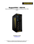
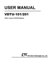
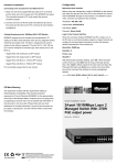
Installation
Connecting to RJ-11
Connecting to Gigabit Ethernet
• Please ensure suitable VDSL Modem (SP3501AS) is
• The VDSL Switch has 2 x 10/100/1000 Mbps Gigabit Ethernet
• ports.
• installed before making a connection to any of the VDSL
• Switch (1-8) station ports. Users need to prepare 18 ~ 26
• gauge one twist pair phone Line wiring with RJ-11 plugs at
• Support full or half-duplex operation and transmission mode is
• using auto-negotiation.
• both ends.
• The Modem's RJ-11 ports are easy-to-use and do not require
• All network devices connected to the switch must support
• installation of additional wiring. Every RJ-11 modular phone
• auto-negotiation. Devices without auto-negotiation will operate
• jack in the home can become a port on the LAN.
• at half-duplex.
• Networking devices can be installed on a single telephone
• Upgrade devices to support auto-negotiation and auto-
• wire that can span up to maximum of 1.7km between the two
• crossover (MDI/MDIX) for full-duplex operation.
• points.
• Prepare straight through shielded or unshielded twisted-pair
• SP3508A has embedded Splitter between every VDSL side
• cables with RJ-45 plugs on both ends. Use 100 Category 5
• (VDSL Line) and POTS side (POTS port). It permits user to
• cable for connections.
• deliver broadband service on the same lines as Plain Old
• When inserting an RJ-45 plug, be sure the tab on the plug
• Telephone Service (POTS), PBX, ISDN traffic and VDSL
• clicks into position to ensure that it is properly seated.
• Signal.
• Connect one end of the cable to port 9 or 10 of the VDSL
• Switch, and the other end to a standard RJ-45 station port on
• When inserting a RJ-11 plug, be sure the tab on the plug
• clicks into position to ensure that it is properly seated.
• cable modem, ADSL router, wireless bridge, etc.
Web-based User Interface
• Do not plug a RJ-11 phone jack connector into the Ethernet
SP3508A is embedded with web-based
• port (RJ-45 port). This may damage the VDSL. Instead, use
UI and provides a series of web pages,
• only twisted-pair cables with RJ-45 connectors that are
which display the configuration and status of the system. After
• compliant with the FCC standards
configuration of IP, the management interface can be access by
entering the IP address of the switch into the browser.
5
6
IP Address
192.168.16.250
Subnet Mask
255.255.255.0
Username
admin
Password
123
IP Address Configuration
PC/Notebook must belong in the same IP range and subnet.
Follow the steps below to configure IP settings for LAN PC.
Step 1.
In the control panel, double click on
Network Connections. Double click
on the local area connection (e.g.
LAN). The following screen will
appear. Highlight 'Internet Protocol
(TCP/IP)' and click on 'Properties'.
Step 2.
Enter the IP address
Quick Installation Guide
192.168.16.x and subnet mask
8-Port VDSL Managed Switch
255.255.255.0 then click <OK>.
Model No.: SP3508A
P/N: 2300-0504
7
Web: www.micronet.com.tw
Introduction
Key Features
Micronet SP3508A is an EoVDSL (Ethernet over VDSL)
• Compliant with ETSI, ITU, ANSI standards
clustering switch that aggregates 8 VDSL lines into 2 Gigabit
Ethernet uplinks. It delivers cost-effective and high-performance
• Compliant with IEEE802.3 10BASE-T, IEEE802.3u 100BASE• TX and IEEE 802.3ab 1000BASE-T standards
broadband / multimedia services to multiunit building
environments, such as enterprise, campus, hospital, hotel, and
telecom. With QAM-based 4-band VDSL technology, the VDSL
solution dramatically extends Ethernet and supports
• Support 8 x RJ-11 VDSL ports and 8 x RJ-11 POTS ports
• Support 2 x RJ-45 ports of 10/100/1000M for Gigabit uplink
• QAM-based 4-band VDSL
5M/15M/25Mbps symmetrical bandwidth over existing
• Data rate up to symmetrical bandwidth of 25Mbps
telephone-grade wiring up to 1.7 /1.1/0.6KM.
• Wiring range up to 1.7 KM
• Auto-speed function for VDSL link
Package Contents
Prior to the installation of the device, please verify the following
• Built-in POTS/ISDN splitter for POTS/ISDN telephone service
• Support detection of wiring quality with SNR(Signal to Noise
items are in the package:
• Ratio) indications
• SP3508A VDSL Managed Switch
• Full function of Layer 2 managed switch: IEEE 802.1q/p Tag-
• Quick Installation Guide
• based VLAN, IEEE 802.1v Protocol-based VLAN,
• Manual CD
• IEEE802.3ad LACP, IEEE 802.1d Spanning tree, IGMPv2,
• Mounting Accessories
• MAC/IP filtering, Port Mirror, and Broadcast Storm Control
• AC Power Cord
• SNMPv1 and MIBs support: Bridge MIB, Ethernet MIB, MIB II
• Support management via Console Port, Telnet and Web• Based
1
2
LED definition
Physical Description
LED
Status
Operation
PWR
Steady/Green
Device is powering on or reset
ok
Steady/Green
Light on when device is
booting
Off
Turn off when booting is
finished
Steady/Green
Each VDSL port has a LED and
lights up to show good linkage
Steady/Green
Light up steadily to show good
linkage at 10 Mbps
Flash/Green
Flashing to show data
transmission
Steady/Green
Light up steadily to show good
linkage at 100 Mbps
Flash/Green
Flashing to show data
transmission
Steady/Green
Light up steadily to show good
linkage at 1000 Mbps
Flash/Green
Flashing to show data
transmission
(Power LED)
POST
(Power On Self
Testing)
Modem Connectors
Connectors
Description
Type
VDSL (1~8)
Connecting to the VDSL Modem via
a RJ-11 cable
RJ-11
POTS (1~8)
Connecting to the telephone, Fax or
ISDN modem
RJ-11
LINK
(VDSL LED)
10/ACT
Gigabit Ethernet Connecting to an Ethernet network
device
Reset
RJ-45
(Ethernet LED)
Restart the switch
100/ACT
Cabling Requirements
(Ethernet LED)
Connection Type
Cable Requirements
Maximum Length
Ethernet Port
(RJ-45)
100 Mbps: Cat 5 UTP
100 meters max
for MUX or HUB
to endpoint.
10 Mbps: Cat 3-4 UTP
1000/ACT
(Ethernet LED)
VDSL Port
(RJ-11)
18-26 Gauge phone wiring. 5M/5M: 1.7km
Do not recommend 28 or
above Gauge.
3
15M/15M: 1.1km
25M/25M: 600m
4