1
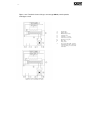
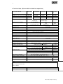
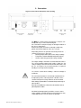
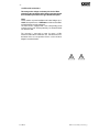
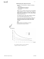
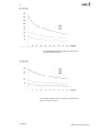
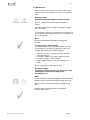
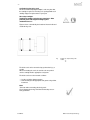
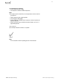
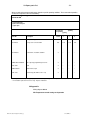
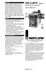
Operating instructions
Gas converter series CG, Version CG-10.
(Units after December 2012)
9-2.0-ME US
M&C Products Analysis Technology
-2-
Table of content
1
Electrical standards
3
2
Safety instructions
3
3
Warranty
4
Used terms and signal indications
4
5
Introduction
5
6
Application
5
6.1
(Figures 1 & 2 ) Functional diagram, sample tpath details
6
7.
Working principle of the conversion
7
.4
7.1
Selection of the appropriate catalyst temperature ............................................................................. 7
8.
Technical data table
9.
Description
8
9
10.
Receipt and storage of goods
10
11.
Installation instructions
11
12.
Supply connections
11
12.1
Hose/tube connections ..................................................................................................................... 12
12.2
Electrical connections .................................................................................................................... 12
13.
Initial use
13
14.
Taking the converter out of operation
13
15.
Determining the catalyst service life
14
15.1.
Figures 4-6, Catalyst life as a funtion of concentrations
14-15
16.1
Replacing the catalyst cartridge ..................................................................................................... 16
16.2
Replacing the O-ring seals .............................................................................................................. 17
16.3
Checking for gas tightness .............................................................................................................. 18
17.
Troubleshooting
18
Appendix ......................................................................................................................................... 20
19
App 1 Electrical Diagram ....................................................................................................................... 21
App 2 PID temperature controller program and settings ..................................................................... 22
This instruction manual is subject to technical modifications. It is the operators responsibility to insure proper training, safety and operating
precautions are observed when using electrical gas analysis equipment. ©11/2000 M&C Products Analysentechnik GmbH. Reproduction of
this document is not allowed without permission from M&C CG® is a registered trade mark.
.
M&C Products Analysis Technology
9-2.0-MEUS
-3-
1. Electrical standards
The electrical standard corresponds to the safety regulations
concerning the European standard EN 61010 and DIN
57721 for testing the voltage of heater elements.
2. Safety instructions
Please note the following basic safety procedures when using
this equipment:
• Read these operating instructions carefully before start-up
and use of the equipment. The information and warnings
given in these operating instructions must be heeded.
• Attention must be paid to the requirements of IEC 364 (DIN
VDE 0100) when setting high-power electrical units with
nominal voltages of up to 1000V, together with the
associated standards and stipulations.
• Work on electrical equipment is only to be carried out by
trained specialists as per the regulations currently in force.
• Check the details on the type plate to ensure that the equipment
is connected up to the correct mains voltage.
• Protection against touching dangerously high electrical
voltages. Before opening the equipment, it must be switched
and hold no voltages. This also applies to any external control
circuits that are connected.
• The equipment is only to be set within the permitted range of
temperatures and pressures.
• The CG-10 is packaged in an enclosed purgeable
instrument case, directly suitable for installation in most
General Purpose classified areas. Operation in hazardous
atmospheres may require case purging, pressure interlocks,
additional enclosures or other protective devices. It is the
responsibility of the operator to insure compliance with
additional requirements for service in hazardous
atmospheres.
• Installation, maintenance, monitoring and any repairs may
only be done by authorized personnel with respect to the
relevant stipulations.
M&C Products Analysis Technology
9-2.0-MEUS
-4-
3. Warranty
If the equipment fails, please contact M&C directly or else go
through your M&C authorized dealer.
We offer a one year warranty as of the day of delivery as per our
normal terms and conditions of sale, and assuming technically
correct operation of the unit. Consumables are hereby excluded.
The terms of the warranty cover repair at the factory at no cost or
the replacement at no cost of the equipment free ex user location.
Reshipments must be send in a sufficient and proper protective
packaging.
4. Used terms and signal indication
These are persons with necessary qualification, who are familiar with
installation, use and maintenance of the product.
SKILLED STAFF
The signals are used according to DIN 4844 and EU
Recommendation 91/C53/06.
These note important information about the product or parts of
the instruction manual which require user’s attention.
9-2.0-ME US
M&C Products Analysis Technology
- 55. Introduction
In combustion processes NOx emissions are frequently present
as a mixture of NO and NO2. Regulatory reporting and process
control systems often require the measurement of total NOx.
Consequently, analytical measurement systems typically require
sensitivity to both species. Many analytical systems rely on the
chemiluminescent measurement principle.
This principal
determines NO concentration by accurately measuring the
amount of light produced by reaction of NO with ozone to
produce NO2. Other analytical methods may also have
sensitivity only to the NO portion of NOx as well. As a
consequence, these types of measurements require that NO2 is
converted back to NO prior to sample entry into the
measurement cell.
Fortunately for most common exhaust
streams and many process applications, thermal or reactive
type conversion of the NO2 can be easily and reliably
accomplished with a heated oven type converter package such
as the CG series.
Due to the non-ventilated case design of the CG-10, it is only
available with the Mo/C (reactive) convertor cartridge which
operates at lower oven temperatures than thermal cartridges.
6. Application
M&C CG series gas converters are designed to convert the
NO2 content of the sample gas by into NO. The conversion can
be accomplished at high temperatures by thermal means, or at
somewhat lower temperatures my means of a proprietary
molybdenum/ carbon (Mo/C) reactive mixture. In either case,
the gas passes through a special stainless steel cartridge with
the appropriate media. The converter allows total NOx, (or NO2)
measurements to be made by analyzer detectors sensitive only
to NO.
M&C offers converters in various versions: CG-2 and CG-2M
with non-heated gas inlet for ‘cold gas’ con-version and CG-2H
respectively CG-2MH with heated gas inlet for ‘hot gas’
conversion.
The CG-10 unit incorporates a purgeable
instrument case, manual bypass valve, and unheated sample
inlet. Due to the non-ventilated case design of the CG-10, it is
only available with the Mo/C convertor cartridge which operates
at lower oven temperatures than thermal cartridges.
The manual bypass valve allows for quick replacement of the
media cartridge without taking the system offline for an
extended length of time. The Mo/C reaction cartridges are
supplied and packaged for simple, quick installation without
needing tools or excessive disassembly of the unit.
M&C Products Analysis Technology
9-2.0-MEUS
-6-
Figures 1 & 2 Functional scheme of the gas converter type CG-10, normal operation,
and in bypass mode
A
B
C
D
E
F
G
H
I
J
Sample Inlet
Sample Outlet
Manual Bypass Valve
Cartridge Oven
Cartridge access knob
Control sensor (type K)
Limit Sensor (type K)
Purge inlet
Purge outlet
Oven temperature PID controller
with undertemperature alarm and
overtemperature protection (Limit
Controller)
- 7-
7. Working principle of the conversion
The conversion of nitrogen dioxide NO2 into nitrogen monoxide
NO occurs according to the following reaction equation:
2 NO2
2 NO + O2
The reaction equilibrium is shifted entirely onto the side of the
original material NO2. A shift of the equilibrium towards the
products and the resultant high product yield can only be
achieved subject to a high expenditure of energy, i.e. temperature
(100% conversion at temperatures over 600 C). By using a
catalyst the activation energy of the above reaction is reduced
considerably so that conversion rates of 99% are possible at
temperatures below 400 C. A carbon-molybdenum mixture is used
as catalyst. The carbon supporting material guarantees optimal
contact between the gas to be converted and the surface of the
catalyst combined with a simultaneously low flow resistance.
The catalyst is supplied as a ready-to-use formatted cartridge.
Note!
For reasons associated with the filter effect of the catalyst filling
an appropriate gas conditioning system is to be mounted
upstream of the converters CG... in order to separate out
suspended particles and to dry the sample gas !
7.1 Selection of the appropriate catalyst temperature The
converter is pre-adjusted to 330 C in the factory. The catalyst
temperature can be adjusted continuously using the
temperature controller on the front of the converter (see 17.2).
The following table shows the recommended settings for
catalyst temperatures depending on the gas flow for a conversion rate above 95%.
Gas flow[Nl/hr]
30
60
90
Setting[ C]
330 C
330 C
340 C
Note!
Ammonia NH3 in the sample gas converts a part of the NO2 into
dinitrogen oxide N2O and elementary N2. Depending on the
ammonia concentration, this can cause a substantial reduction in
the conversion rate!
M&C Products Analysis Technology
9-2.0-MEUS
-8-
8. Technical data (Other models included for comparison)
Gas converter series CG®
Version CG-2
Version CG-2M
Version CG-2H
Part No.
50 A 1600
50 A 1500
50 A 1800
Gas inlet non-heated (cold) or heated (hot)
non-heated
non-heated
heated
Bypass solenoid valve
Temperature of sample gas
Temperature range, adjustable
—
2x
Version CG-2MH Version CG10a
50 A1700
heate
d
1x
—
max. +80 C
max. +250 C
dew point „dry“
dew point <160 C
max. 700 C with 230V
max. 600 C with 115V(a)
Gas flow rate
max.
500 C
with 230V/115V
max. 90Nl/hr
Operating pressure
max. 2bar abs.
Warm-up time
approx. 45min.
Operating temperature at NO2/NO
Conversion NO2/NO
Life of catalyst NO2/NO
NO2/NO-catalyst
Differential pressure
in an exchangeable cartridge
< 20mbar
-25 C to +65 C
Power supply/power consumption
Electrical connection
max.
360 C
with 230V/115V
approx. 12 months, flue gas at flow 30Nl/hr with 10ppm NO2 , 5Vol.-% O2
Storage temperature
Sample gas connection: outlet
max. +80 C
dew point „dry“
30Nl/hr = 330 C; 60Nl/hr = 330 C; 90Nl/hr = 340 C
+10 C to +50 C
Sample gas connection: inlet
Manual valve
efficiency >95% with new catalyst
Ambient temperature
Relative humidity
50 A1206a
Non-heated
< 80%
PVDF-Fitting G1/4“i DIN228/1
Ø6mm tube connector,
SS316*
PVDF connector G1/4“i DIN ISO 228/1
230V, 48-62Hz, 520VA
230V, 48-62Hz,
620VA
or (a) 115V, 48-62Hz, 140VA
or (a) 115V, 48-62Hz,
240VA
mains power plug connector incl. 2 fine fuse 5x20mm,
¼” SS316
¼” SS316
115V, 48-62Hz,
550 VA
Terminal Block
230/3, 15A or 115/3, 15A; 2m cable and shock-proof plug;
Alarm-/control signals 9 pin sub-D connector
Status signals for temperature
Materials of sample contacting parts
NO contact, potential-free, contact rating max. 24V, 1A
st. steel SS316, PVDF, PTFE, FPM, PEEK (only at ...-2H resp ................. MH)
Degree of protection
Housing
IP20, EN60529
Purgeable Case
19“ rack mounting, 84HP(TE), 3U(HE), depth: 350mm
Option:
Wall mounting bracket, 3HE - 84TE
Part no.: 50A3000
Weight
Electrical equipment standard
approx. 6kg
EN61010, EN60519-1
M&C Products Analysis Technology
The M&C gas converter CG-10 is designed as a compact, userfriendly and easy to service wall mounting unit.
Gas connection for sample and purge are through the bottom of
the case as shown above.
Electrical and signal connections are through conduit entry
glands on the bottom right rear of the case as shown.
All operating elements are mounted on the front panel of the ;
converter for easy access. These are:
•
Mounting adapter with handle for the catalyst cartridge
•
Temperature controller with digital temperature display
•
Selector switch for bypassing the catalyst cartridge
The catalyst cartridge is mounted in a heat-insulated tube furnace.
The special mounting adapter with handle 2 allows the hot
catalyst cartridge to be released and removed without tools. But
the use of hot gloves for personnel protection is required if
handling a hot, freshly removed cartridge.
Use extreme caution when handling a removed cartridge to
avoid burns
The converter temperature is electronically controlled and can
be adjusted by means of the temperature controller 3 on the
converter front panel in a range between +50 C and +360 C,
Mo/C cartridges operate within a recommended temperature range of
320°C to 340°C.
Due to the non-ventilated case of the CG-10, the maximum oven set
point temperature is 360°C.
One alarm for low-temperature is provided as a status contact
output, available on the DIN rail mounted general purpose relay
socket within the unit. Form C contacts are provided.
M&C Products Analysis Technology
9-2.0-MEUS
- 10
10.Receipt and storage of goods
The CG... converter is a completely pre-installed unit. The
standard catalyst cartridge supplied is already installed.
• Remove the CG... converter and any accessories carefully from the transport
packaging immediately after arrival and check the contents of the delivery
against the delivery note;
• Check the goods for any transport damage and if necessary inform your transport
insurer immediately of any damage.
Note!
The converter should be stored in a protected frost-free
room!
9-2.0-MEUS
M&C Products Analysis Technology
- 11 11.Installation instructions
The converter is designed as a 14” W x 5” H x 10” D wall mounting
case, with a mount plate on the back wall of the unit.
Note!
If mounting outdoors, the converter should be installed in an area
protected from direct weather, freezing, or direct sunlight.
Exposure to the elements will degrade the user controls and may
result in corrosion of the case.
In order to avoid the re-oxidation of NO and NO2 in long sample
lines, the converter should be mounted in close proximity to the
gas analyser. Long sample lines, exposure of the sample to
sunlight (or UV radiation) may result in re-formation of NO2 and
loss of sample.
The converter should be installed away from sources of heat
and in a position which allows air to circulate freely in order to
avoid any disruptive heat build up.
12.Supply connections
12.1 Hose/tube connections
The gas inlet and outlet hoses/tubes are connected on the bottom
of the converter. CG-10 units provide sample and case purge
connections through the case bottom, via ¼” SS compression
fittings.
The appropriate tube or hose threaded joint connections are
available optionally from M&C.
Note!
Do not confuse hose/tube connections for sample gas inlet and
outlet; the connections are labelled accordingly!
Check for tightness after connection!
The tightness of the connections can only be guaranteed if the end
section of the connection hose/tube is flat (use a hose cutter)!
M&C Products Analysis Technology
9-2.0-MEUS
- 12 -
12.2 Electrical connections
The wrong mains voltage can destroy the device. When
connecting, take care that the mains voltage corresponds with
the information provided on the type identification plate!
Note!
For the erection of power installations with rated voltages up to
1000V, the requirements of VDE 0100 and relevant standards
and specifications must be observed!
The main circuit is equipped with a fuse corresponding to the
nominal current (over current protection); for electrical details
see technical data. .
The converter is connected to power by means of DIN
mounted terminal blocks within the unit. Conduit entries into
the bottom of the case are provided. Please see the electrical
diagram for terminal details.
9-2.0-ME US
M&C Products Analysis Technology
- 13 -
13. Initial use
Before using the equipment for the first time, check that the
safety measures specific to the installation and process are
complied with!
The following steps are to be taken before using for the first
time:
• Connect converter to the mains; compare the mains voltage
with the information on the identification plate before starting
up;
• If necessary, connect general alarm contact to the measurement control station;
• Switch sample gas path to ‘bypass’;
• Insert catalyst cartridge into the mounting adapter (see
16.1);
• Introduce cartridge into the tube furnace and lock into place
by turning the adapter handle;
• Set desired catalyst temperature (see 7.1, pre-adjusted at
330 C) using the temperature controller. The warm-up time is
approximately 45 minutes;
• When the desired temperature is reached, switch sample gas
path over to catalyst operation internally or externally.
Note!
The maximum working temperature of the converter is 360 C
with CG-10 models. a
When using a new catalyst cartridge for the first time or after
longer periods of storage at room temperature, the response
time T90 can be substantially longer !
14.Taking the converter out of operation
Note!
The location at which the converter is mounted must remain frostfree even when the device is switched off!
No special measures need to be taken when the converter is
taken out of operation for a short period.
In order to avoid unnecessary consumption of the catalyst and to
ensure that the catalyst is ready for use at short notice, the
catalyst temperature should be reduced below 300 C in the
‘stand-by’ during brief operational pauses.
When the converter is taken out of operation for more protracted periods, we recommend rinsing the converter with inert
gas or air at ambient temperature, switching off the voltage and
interrupting the gas supply.
9-2.0-MEUS
M&C Products Analysis Technology
- 1415.Determining the catalyst service life
The catalyst service life depends essentially on the following
factors:
• temperature,
• NO2-concentration in the sample gas,
• O2-concentration in the sample gas,
• gas flow rate.
Figures 5 up to 7 show the service life curves of the NO2/NO
catalyst depending on above mentioned factors. During the
stated service life, conversion is over 95%. If the degree of
efficiency falls notably below 95%, the used catalyst cartridge
should be replaced (see 16.1).
The sample gas flow rates 30l/hr, 60l/hr and 90l/hr are assigned
to the corresponding working temperatures (see 7.1).
The curve values were determined under laboratory conditions and
are intended to enable the user to be better able to estimate
catalyst service life under practical conditions in the relevant
installation.
Note!
Adverse conditions in the installation can lead to a
substantially shorter catalyst service life!
Fig. 4: Catalyst life depending on the NO2-concentration for
varying flow rates and an O2-concentration of 5Vol.-%
M&C Products Analysis Technology
9-2.0-ME US
- 15 -
Fig. 5: Catalyst life depending on the NO2-concentration for varying flow rates
and an O2-concentration of 10Vol.-%
Fig. 6: Catalyst life depending on the NO2-concentration for varying flow rates
and an O2-concentration of 21Vol.-%
9-2.0-ME US
M&C Products Analysis Technology
- 16 16. Maintenance
Before carrying out maintenance work, make sure that safety
measures specific to the installation and process are complied
with!
Dangerous voltage!
Remove mains plug before opening the converter’s housing!
The CG... converter does not need special maintenance
periods.
When replacing the catalyst cartridge, it is advisable to change
the seals provided.
The temperature controller is implemented in the front panel of
the converter and the controller housing can be easily taken out
of the converter front.
Note!
Remove mains plug before dismantling the temperature
controller!
16.1 Replacing the catalyst cartridge
The catalyst cartridge can be replaced without the aid of tools.
The converter does not need to be switched off to replace the
cartridge. The following steps should be followed:
• Switch the converter’s sample gas path either internally
or externally to bypass;
• Unscrew the adapter of the catalyst cartridge by turning
the screw 2 (see fig. 3) counter-clockwise.
• Pull the catalyst cartridge out of the tube furnace by the
handle;
The re-inserting happens in the opposite way.
Hot catalyst cartridges.
Touching the cartridge can lead to very severe burns. Wear
protective gloves and safeguard cartridge against
unauthorized access!
Note!
In order to obtain the required gas-tightness, take care that the
cartridge is always inserted into the adapter right up to the stop.
Moisten the outer O-rings helps placing the cartridge into the
oven.
Do not use grease for O-rings because it could affect the
efficiency of the catalyst!
M&C Products Analysis Technology
9-2.0-ME US
- 17 -
16.2 Replacing the O-ring seals
We also recommend replacing the adapter’s seals every time that
the cartridge is replaced. An O-ring set is packaged with each
cartridge shipped as replacement or spare part.
Hot catalyst cartridges.
Touching the cartridge can lead to very severe burns. Wear
protective gloves and safeguard cartridge against
unauthorized access!
Figure 8 shows schematically the location of the two inside and
outside O-ring seals.
Fig.
8: Adapter for catalyst cartridge with
handle
The inside seals can be removed using a pointed tool (e.g. a
needle).
When re-mounting the seals, the outside seals are pushed
over the cartridge into the appropriate seal groove.
The inside seals are to be mounted as follows:
• Lay the seal in the adapter aperture;
• Push the O-ring into the appropriate seal groove using a blunt
instrument.
Note!
Take care when re-mounting the O-ring seals:
Do not damage the O-rings and take care that they are correctly positioned!
9-2.0-ME US
M&C Products Analysis Technology
-18-
16.3 Checking for gas tightness
• Connect device to mains supply;
• Set temperature controller to ambient temperature;
Note!
The converter must be cooled down to room temperature in order to check for
gas tightness!
• Switch sample gas path to catalyst operation
• Seal sample gas outlet tightly;
• Connect sample gas outlet with U-tube manometer or similar for 0,6bar and
upstream stopcock;
• Release air using the stopcock until the manometer displays a pressure of
approximately 0,5bar;
•Close stopcock;
A pressure drop of 0,01bar in 5 minutes is acceptable.
Note!
Do not exceed the maximum operating pressure of 2bar absolute!
M&C Products Analysis Technology
M&C Products Analysis Technology
-19-
17.Trouble shooting
Problem/Display
Possible cause
Check/Rectification
PID does not light up
No indication of power to unit
No mains power
Mains ‘ON’;
:
Check that mains terminals are
connected
Fuse has failed
Check and replace 10A line fuse as
necessary
PID has power, and displays
temperature but oven fails to heat
1
PID has power, output ‘2’ LED is
illuminated and/or flashing, ‘4’ LED
is not illuminated (visible) but oven
fails to heat
Observe if LED ‘2’ output is
PID program revised or corrupted. flashing. Oven heater should have
power if ‘2’ is illuminated, provided
that the overtemperature (latching
alarm) has not tripped. LED ‘4’
Controller has tripped on over
should not be illuminated.
temperature limit.
If ‘4’ is illuminated, reset the limit
alarm on the PID controller.
If ‘2’ does not illuminate, check and
correct PID programming, or
replace defective PID
Broken/failed wiring
Heater defective
SSR has failed
PID has power, temperature display
shows alarm (blinks)
Control or limit thermocouple
failure
Insufficient conversion, loss of NOx Mo/C cartridge requires
response
replacement. Sample leak.
No sample gas flow
Pluggage of hoses, cartridge, or
fittings due to contamination in
sample stream
Inspect wiring and terminal
connections.
With power disconnected, check
heater resistance. Should be
approximately 25 ohms, and have
no continuity to ground. Replace if
defective.
Apply power to unit. **Caution!!
Live voltage **. Carefully check
heater terminals for 117 VAC. If
none, determine if SSR has low
voltage DC control signal. Replace
if defective.
Check thermocouple connections.
Replace failed thermocouple (limit)
or heater assembly (control TC)
.
Replace cartridge 95A9003.
Perform leak check and/or inspect
hoses and cartridge O-rings
Inspect hoses, fittings and valve for
flow restriction. Repair or replace
as needed. Replace cartridge
95A9003
18.Spare parts list
-20-
Wear, tear and replacement part requirements depend on specific operating conditions. The recommended quantities
are based on experience and are not binding.
Converter CG®
...
(C) Consumable parts
(R) Recommended spares
(S) Spare parts
Recommend
in operation[years]
Part No.
Description
95 A 9003
Catalyst cartridge CG2-C
95 A 9070
O-ring set for converter CG2
95 A 9057a
Heater CG-2; 115/230V, 50/60Hz
PM6C1EC-ALAJAAA
quantity
C/R/S
1
C
b.d.*
b.d.*
b.d.*
b.d*
b.d*
b.d*
S
*
*
*
PID **Specify programming for CG-10
S
*
*
*
601-0097
SSR
S
*
*
*
KMTSS032U
Limit Thermocouple
S
*
*
*
834-1330
Alarm Relay (GP, DPDT, 120 V coil)
S
*
*
*
R/C
2
3
b.d.* = by demand. O-rings are typically replaced with cartridge change. Further replacement should not be necessary.
* = Preventative replacement not necessary. Replace if defective
20.Appendix
Wiring diagram GC-10
PID Temperature control settings and operation
M&C Products Analysis Technology
9-2.0-MEUS