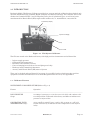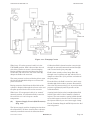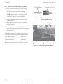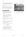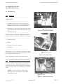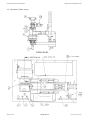
1
INSTRUCTION 67-9319
INJECTOR CALIBRATOR CD3
Part Number 67-7622 to 67-7627
Installation/Operation/Maintenance
Rev. 8 – January, 1999
Bacharach, Inc.
621 Hunt Valley Circle, New Kensington, PA 15968-7074
Phone: 724-334-5000 • FAX: 724-334-5001 • Web: www.bacharach-inc.com
Printed in U.S.A.
WARRANTY
Bacharach, Inc. warrants to Buyer that at the time of delivery this Product will be free from
defects in material and manufacture and will conform substantially to Bacharach Inc.’s
applicable specifications. Bacharach’s liability and Buyer’s remedy under this warranty are
limited to the repair or replacement, at Bacharach’s option, of this Product or parts thereof
returned to Seller at the factory of manufacture and shown to Bacharach Inc.’s reasonable
satisfaction to have been defective; provided that written notice of the defect shall have been
given by Buyer to Bacharach Inc. within one (1) year after the date of delivery of this Product
by Bacharach, Inc.
Bacharach, Inc. warrants to Buyer that it will convey good title to this Product. Bacharach’s
liability and Buyer’s remedy under this warranty of title are limited to the removal of any
title defects or, at the election of Bacharach, to the replacement of this Product or parts
thereof that are defective in title.
The warranty set forth in paragraph 1 does not apply to parts the Operating Instructions
designate as having a limited shelf-life or as being expended in normal use.
THE FOREGOING WARRANTIES ARE EXCLUSIVE AND ARE GIVEN AND
ACCEPTED IN LIEU OF (i) ANY AND ALL OTHER WARRANTIES, EXPRESSED OR IMPLIED, INCLUDING WITHOUT LIMITATION THE IMPLIED WARRANTIESOF MERCHANTABILITY AND FITNESS FOR A PARTICULAR PURPOSE: AND (ii) ANY
OBLIGATION, LIABILITY, RIGHT, CLAIM OR REMEDY IN CONTRACT OR TORT,
WHETHER OR NOT ARISING FROM BACHARACH’S NEGLIGENCE, ACTUAL OR
IMPLIED. The remedies of the Buyer shall be limited to those provided herein to the
exclusion of any and all other remedies including, without limitation incidental or
consequential damages. No agreement varying or extending the foregoing warranties,
remedies or this limitation will be binding upon Bacharach, Inc. unless in writing, signed by
a duly authorized officer of Bacharach.
NOTE: Fuses and gaskets are expendable items and are excluded from the terms of this
warranty.
A
Bacharach, Inc.
Instruction 67-9319
TABLE OF CONTENTS
1.0 INTRODUCTION ............................................................................................................. 1-1
1.1
1.2
1.3
1.4
1.5
1.6
1.7
Calibrator Features .................................................................................................. 1-1
Accessories ................................................................................................................ 1-5
Construction .............................................................................................................. 1-6
Calibration Fluid System ........................................................................................ 1-7
Calibration Fluid Temperature Control System ................................................... 1-10
Pneumatic System .................................................................................................. 1-11
Electrical System .................................................................................................... 1-11
2.0 INSTALLATION ............................................................................................................... 2-1
2.1
2.2
2.3
2.4
2.5
2.6
2.7
2.8
2.9
Selecting the Site ...................................................................................................... 2-1
Hold Downs ............................................................................................................... 2-1
Utility Connections ................................................................................................... 2-2
Filling Reservoirs ...................................................................................................... 2-3
Pre-operation Checks ................................................................................................ 2-4
Initial Checks ............................................................................................................ 2-4
Start-up ..................................................................................................................... 2-6
Repacking for Shipping ............................................................................................ 2-7
Shipping and Storage ............................................................................................... 2-7
3.0 OPERATION ..................................................................................................................... 3-1
3.1 Cummins Injectors .................................................................................................... 3-1
3.1.1 Quick Reference Chart .................................................................................. 3-1
3.1.2 Changing Speed ............................................................................................. 3-2
3.1.3 Changing Cams ............................................................................................. 3-3
3.1.4 Inserting the Cummins Discharge Head ...................................................... 3-4
3.1.5 Mounting Cummins Type PTD Cylindrical Injectors .................................. 3-5
3.1.6 Mounting Cummins Types PTB and PTC Cylindrical Injectors ................. 3-8
3.1.7 Mounting Flanged Injectors ........................................................................ 3-11
3.1.8 Testing ......................................................................................................... 3-13
3.1.9 Unclamping .................................................................................................. 3-44
3.1.10 Removing Injectors and Shutting Down Calibrator ................................... 3-14
3.2 Detroit Diesel (DD) Injectors .................................................................................. 3-15
3.2.1 Quick Reference Chart ................................................................................ 3-15
3.2.2 Changing Speed ........................................................................................... 3-15
3.2.3 Changing Cams ........................................................................................... 3-16
3.2.4 Mounting DD Injector Types 53, 71, and 92 ............................................... 3-18
3.2.5 Mounting DD Injector Type 149 ................................................................. 3-21
3.2.6 Mounting DD Injector Type 8.2 Liter ......................................................... 3-23
3.2.7 Testing ......................................................................................................... 3-25
3.2.8 Unclamping .................................................................................................. 3-27
3.2.9 Removing Injectors and Shutting Down Calibrator ................................... 3-28
Instruction 67-9319
Bacharach, Inc.
i
TABLE OF CONTENTS (cont.)
4.0 MAINTENANCE & TROUBLESHOOTING ................................................................... 4-1
4.1 Maintenance .............................................................................................................. 4-1
4.1.1 Schedule ......................................................................................................... 4-1
4.1.2 Changing Calibration Fluid and Filters ....................................................... 4-1
4.1.3 Changing Cambox Oil ................................................................................... 4-3
4.1.4 Cleaning and Lubricating ............................................................................. 4-3
4.1.5 Checking Flowmeter Cavity .......................................................................... 4-3
4.2 Troubleshooting ........................................................................................................ 4-4
4.4.1 Charts ............................................................................................................. 4-4
4.4.2 Hydraulic System .......................................................................................... 4-6
4.4.3 Replacing O-ring in Fuel Arm ....................................................................... 4-7
4.4.4 Resetting Switches ........................................................................................ 4-7
4.4.5 Changing Fuses ............................................................................................. 4-8
4.4.6 Checking Main PC Board .............................................................................. 4-9
4.3 Adjustments ............................................................................................................ 4-10
4.3.1 Calibration Fluid Temperature Adjustment .............................................. 4-10
4.3.2 Air Pressure Regulator Adjustment ........................................................... 4-10
4.3.3 Adjusting Pulley cover Interlock ................................................................. 4-11
4.3.4 Adjusting Optical Detector on Camshaft .................................................... 4-11
4.3.5 Motor Starter Overload Relay Setting ........................................................ 4-11
4.3.6 Changing Drive Belt .................................................................................... 4-11
4.3.7 Replacing Push Rod Shear Pin ................................................................... 4-13
5.0 ILLUSTRATED PARTS LIST .......................................................................................... 5-1
5.1
5.2
5.3
5.4
5.5
5.6
5.7
5.8
5.9
5.10
5.11
5.12
5.13
5.14
5.15
Console, Front and Side Views ................................................................................. 5-2
Console, Rear View ................................................................................................... 5-4
Cabinet, Front View & Left Side View ..................................................................... 5-5
Cabinet, Top View ..................................................................................................... 5-7
Operator’s Table ........................................................................................................ 5-9
Optical Detector ...................................................................................................... 5-11
Cambox Assembly ................................................................................................... 5-12
Calibration Fluid Plumbing System ...................................................................... 5-13
Pneumatic and Hydraulic Plumbing Systems ....................................................... 5-14
Calibrator Wiring Harness ..................................................................................... 5-15
Electrical Control Panel ......................................................................................... 5-18
Electrical Power System ......................................................................................... 5-20
Standard Calibrator Accessories ............................................................................ 5-24
Accessories for use with Cummins Injectors ......................................................... 5-25
Accessories for use with DD Injectors .................................................................... 5-26
APPENDIX A Calibrator Audit Kit
ii
Bacharach, Inc.
Instruction 67-9319
TECHNICAL DATA AND FEATURES
•
Synchronous drive motor
•
Digital fuel measurement
•
Floor standing unit; full welded frame construction
•
Operating speeds: 1050 RPM (Cummins), 2000 RPM (DD)
•
Cast iron cambox with tapered roller bearings and quick change cam capability
•
Injector clamping: hydraulic
•
Calibration fluid reservoir capacity: 8 U.S. Gallons (30 liters)
•
Filtration:
- Primary filter (spin-on type):
- Final stage filter:
- Flowmeter transducer:
•
10 micron
3 micron
screen
Calibration fluid temperature control:
- Solid state control
- 104°F + 1°F (factory setting)
- Cooling by cold tap water
- Heating by two 500 watt immersed electric heaters
•
Instrumentation & Controls:
- Injector Supply (Rail) Pressure Gauge, 4" Dial, Scale: 0-200 psi.
- Calibration Fluid Temperature Gauge, 4" Dial, Dual Scale: 40-140°F (5-60°C).
- Supply pressure regulator
- Clamping pressure regulator
- Main drive start, stop switches
- Measurement system start switch
•
Measurement System:
- Positive displacement Flowmeter (U.S. Patent No. 4141243)
- Measurement Units - mm3/str.
- Digital display resolution - 0.1 mm3/str.
- Measurement sampling - 50 or 100 strokes
- Stroke counter - electronic/optical
- Accuracy: + . 75% of reading or 1 mm3/str. whichever is greater
Instruction 67-9319
Bacharach, Inc.
iii
TECHNICAL DATA AND FEATURES (Continued)
•
Indicator Lights:
- Power (red) - Heat/Cool (amber) - Clamping (amber).
•
Accessibility: Two front and one upper left hand side hinged doors. All other panels have quick
turn fasteners for easy removal.
•
Dimensions: 50"W (1.27m) x 30"D (.76m) x 56" H (1.42m)
•
Weight (Dry): 1150 lbs. (521 kg)
•
Utilities Required:
- Electrical:
Part #
Voltage
67-7622
67-7623
67-7624
67-7625
67-7626
67-7627
230 VAC
460 VAC
208 VAC
220 VAC
380 VAC
440 VAC
ELECTRICAL OPTIONS
Phase
Freq.
3 HP Motor
Amps
3
60 Hz
24
3
60 Hz
12
3
60 Hz
26
3
50 Hz
25
3
50 Hz
15
3
50 Hz
13
5 HP Motor
Amps
33
17
38
35
20
18
- Air Pressure: 80-120 psi (2 CFM).
- Water: Cold tap, approximately 1.2 GPM (4.5 liter/min).
•
Accessories:
- Accessories are available for mounting and testing of all Cummins
injectors (mechanical) and injectors (mechanical) manufactured by
Diesel Technology Corporation for engine models 53, 71, 92, 92 marine,
149, and 8.2L. These accessories must be ordered separately.
- Provision for hanging all accessories on pegboard inside lower doors.
iv
Bacharach, Inc.
Instruction 67-9319
INJECTOR CALIBRATOR CD3
INTRODUCTION
1.0 INTRODUCTION
Bacharach Model CD3 Injector Calibrator provides fast, accurate and safe calibration of mechanical unit
injectors manufactured by Cummins Engine Company and Diesel Technology. The calibrator will accommodate the Cummins H-NH, J, and C flanged injectors, plus all cylindrical types, as well as injectors
manufactured for Detroit Diesel (DD) engine model numbers 53, 71, 92, 92 Marine, 149, and 8.2L.
F u e l D e liv e r y D is p la y
In je c to r F u e l S u p p ly
C la m p
In je c to r C r a d le
Figure 1-1. CD3 Injector Calibrator
The CD3 was tested at the Bacharach factory with high precision instruments and calibrated for:
•
•
•
•
•
•
Injector supply pressure
Calibration fluid temperature
Flowmeter and calibrator accuracy
Correct clamping forces (body-to-seat and plunger-to-body)
Discharge head (Cummins) performance
Accuracy with Detroit Diesel (DD) master injectors
These can be checked and recalibrated, if necessary, by a qualified service technician using precision
equipment available from Bacharach in an Audit Kit (part number 67-7707). See Appendix A.
1.1 Calibrator Features
INSTRUMENT CONSOLE FEATURES (Refer to Fig. 1-2)
Feature
Operation
_________________________________________________________________________________________________
RAIL PRESSURE
Gauge
0 to 200 psi, accurate to ± 1/4%, has a 4-1/2 in. dial, and a mirror scale
to avoid parallax. Calibrated at the factory and offset to indicate true
pressure at injector inlet.
CALIBRATION FLUID
TEMPERATURE Gauge
40° to 140°F (5° to 60°C) has a 3-1/2 in. dial, accurate to ± 1°F (calibrated at the factory to indicate the true temperature at the injector
inlet).
Instructions 67-9319
Bacharach, Inc.
Page 1-1
INTRODUCTION
INJECTOR CALIBRATOR CD3
M M
P O W E R
In d ic a to r
S T R O K E S
S w itc h
3
/S T R O K E
D is p la y
C A L IB R A T IO N F L U ID
T E M P E R A T U R E G a u g e
S T A R T M E T E R
S e le c to r
H O U R S
M e te r
R A IL P R E S S U R E
G a u g e
C L A M P M O N IT O R /T IM IN G
P L U N G E R T O B O D Y G a u g e
P R E S S U R E
R E G U L A T O R
P lu n g e r to b o d y c la m p
tim in g in d ic a to r
S T A R T M A IN
D R IV E
H E A T E R
In d ic a to r
T E M P E R A T U R E
A d ju s tm e n t
C L A M P M O N IT O R
B O D Y T O S E A T
Figure 1-2. Console Features
Feature
Operation
_____________________________________________________________________
START METER Button
(Flowmeter)
Switches on flowmeter. Lights while meter is running.
MM3 / STROKE
Display (Flowmeter)
Four-digit LED display with resolution of 0.1 mm3/stroke (Red
flashing dot indicates update in LED display).
STROKES Selector
Switch (Flowmeter)
Selects 50 or 100 strokes per reading.
POWER “ON”
Indicator (light)
When lit, indicates that the On/Off Switch is closed, and the pump
for circulating calibration fluid and providing clamping pressure is
operating.
HOURS Meter
0 to 9999 hours (counts total hours while On/Off Switch is on).
CLAMP MONITOR/
TIMING, PLUNGER
TO BODY gauge
Factory set to indicate proper plunger-to-body clamp force. When
pointer points to the green segment of the dial, clamping force is
380 lb ±10 lb.
Plunger to Body Clamp
Timing Indicator (light)
Lights for about 3 seconds during clamping operation.
START MAIN
DRIVE Button
Applies power to main drive motor. Starts camshaft rotation
and the injector supply pump.
HEATER “ON”
Indicator
When lit, indicates power is being applied to calibration fluid
reservoir heater.
TEMPERATURE
Adjustment
(Potentiometer)
Permits manual setting of calibration fluid temperature.
Page 1-2
Bacharach, Inc.
Instructions 67-9319
INJECTOR CALIBRATOR CD3
INTRODUCTION
Feature
Operation
_____________________________________________________________________
CLAMP MONITOR
BODY-TO-SEAT
(Cummins)
Monitors the injector body-to-seat clamping force. When clamping
force is low, the indicator shows black. When clamping force is
correct, the indicator shows green.
PRESSURE
REGULATOR
RAIL PRESSURE gauge
Precision diaphragm-type pressure regulator allows the pressure of
the calibration fluid supply to the injector to be set as indicated on
the (Injector Supply).
H o le P r o v id e d to
K e e p B a r r in g T o o l
H O L D T O O P E R A T E
"A " O R "B "
B O D Y T O
S E A T R E L E A S E
S T O P S w itc h
O n /O ff S w itc h
Figure 1-3. Left Table Features
LEFT OPERATOR’S TABLE FEATURES
Feature
Operation
_____________________________________________________________________
On/Off Switch
For switching the control circuit power on and off.
When switched on, starts the clamp pump motor which
then runs constantly. Also turns on the calibration
fluid automatic temperature control and hour meter.
STOP Button
Shuts down main drive motor.
BODY TO SEAT
RELEASE Button
Applies air pressure to the two clamping cylinders that
drive the body to seat clamp cylinders to the full,
extended (release) position.
HOLD TO OPERATE
Unlocks the main clamp cylinder. Functions only when
main drive motor is OFF.
Instructions 67-9319
Bacharach, Inc.
Page 1-3
INTRODUCTION
INJECTOR CALIBRATOR CD3
Feature
Operation
___________________________________________________________________
“A” OR “B” Button
There is no physical movement of the clamping mechanism
when this button is pressed but it must be held down to
operate the body to seat clamp or plunger to body clamp.
This is part of the two hand safety operation system.
_____________________________________________________________________
B O D Y T O
"A "
S E A T C L A M P
"B "
P lu n g e r to B o d y C L A M P
Figure 1-4. Right Table Features
RIGHT OPERATOR’S TABLE FEATURES
Feature
Operation
___________________________________________________________________
“A”
BODY TO SEAT
CLAMP Button
Clamps body to seat. Will operate only when flywheel
is in a certain angular position and the HOLD TO
OPERATE “A” or “B” button is held down.
“B”
Clamp/Unclamp lever
(4-way selector valve)
Clamps plunger to injector body. Will operate only
when the HOLD TO OPERATE “A” or “B” button is
held down.
Page 1-4
Bacharach, Inc.
Instructions 67-9319
INJECTOR CALIBRATOR CD3
INTRODUCTION
1.2 Accessories
B a r r in g T o o l
D r a in H o s e
C u m m in s A c c e s s o r ie s
( O r d e r S e p a r a te ly )
D D A c c e s s o r ie s
( O r d e r S e p a r a te ly )
Figure 1-5. Accessories
The accessories for the CD3 come in three different sets.
1.
The Basic Accessories (not shown) supplied with.
2.
Accessories for the Cummins Injectors.
3.
Accessories for the DD Injectors.
A lists of all parts in the accessories kits are given in Chapter 5. Accessories for testing Cummins or DD
injectors are supplied if ordered separately. They come with hooks for hanging them inside the front doors.
Instructions 67-9319
Bacharach, Inc.
Page 1-5
INTRODUCTION
INJECTOR CALIBRATOR CD3
1.3 Construction
Cabinet: The frame is of welded steel 1-1/4 inch
square tubing and angle iron. The upper left side
and both front doors are easily accessible for
changing speed, storing accessories, and performing
routine maintenance through hinged doors. All
other external panels are secured with 1/4-turn
fasteners for easy removal. Rotating parts are
protected with a hinged cover, safety interlocked
with the main drive motor.
In s tr u m e n t C o n s o le
O p e r a to r s T a b le
H y d r a u lic C y lin d e r
Console and operator’s table: The instrument
console is mounted to the operator’s table with
vibration absorbing mounts for the controls and
gauges. Vibration absorbing leveling pads are
provided for easy leveling of the unit.
Calibration Fluid Reservoir: The calibration
fluid is stored in a 8 U.S. gallon (30 liter), thermostatically controlled reservoir which is used in
common by the injector test fuel supply and the
clamping circuits. Contained in the reservoir are
two 500-watt electric heaters and a cooling coil. The
reservoir also has a dipstick and two drain valves.
Injector clamping: Injectors are clamped using a
hydraulic cylinder. The cylinder is locked mechanically at all times. An air driven hydraulic pump
called an intensifier provides the high pressure
required to unlock the clamp cylinder.
C ir c u la tin g a n d C la m p in g
M o to r a n d P u m p
C a lib r a tio n
F lu id R e s e r v o ir
Figure 1-6. Cabinet, Console, Operators Table,
Reservoir & Clamping
P u lle y s
F ly w h e e l
( h id d e n )
C a m b o x
Pneumatic clamping: Two double-acting air
cylinders are used in clamping the Cummins
injectors body to seat.
Circulating and clamp cylinder pump: A 1/3
HP electric motor drives the gear pump supplying
fluid to the double-acting hydraulic cylinder which
clamps and unclamps the injector. The motor and
pump run continuously which keeps the calibration
fluid circulating to stabilize fluid temperature.
Main drive motor: The calibrator is powered by
an1800 RPM synchronous speed electric motor
operated by a starter with overload protection. This
motor drives the camshaft which in turn activates
the plunger in the injector being tested. The motor
also drives the injector supply pump.
Pulleys: A pulley arrangement between the main
motor drive shaft and the cam shaft offers two
speed settings. The motor is mounted on a hinged
plate and a barring tool inserted into the yoke
permits quick speed change over from CUM (1050
RPM) to DD (2000 RPM) or vice versa.
Page 1-6
M a in D r iv e M o to r
Figure 1-7. Main Motor, Pulleys, Flywheel, &
Cambox
Bacharach, Inc.
Instructions 67-9319
INJECTOR CALIBRATOR CD3
INTRODUCTION
Flywheel: A flywheel is mounted on the driven
end of the camshaft for uniform rotation. An
encoder wheel, also mounted on the camshaft in
conjunction with an optical pickup, counts strokes.
Cambox: The cambox is constructed of cast iron
and contains a 1-1/2 inch diameter camshaft
supported by heavy duty tapered roller bearings.
The cam is mounted to one end of the shaft on a
non-locking taper, secured by a nut and washer.
The driving torque is transmitted by a key and
keyway which allows quick and easy cam changes.
The rotating cam dips and splashes to lubricate the
cam, bearings, tappet, roller, and pusher rod.
Flowmeter transducer: For measuring fuel
output of the injector, the calibrator uses a positive
displacement flow measuring device with a digital
readout.
C a m s h a ft
1.4 Calibration Fluid System (Figure 1-10)
N u t a n d W a s h e r
L u b r ic a tin g O il
Figure 1-8. Cambox Parts
The calibration fluid system consists of three
separate circuits:
a. The clamp and unclamp circuit, which also
provides continuous circulation of calibration
fluid for close temperature control.
b. The injector supply circuit (rail pressure).
c.
The flowmeter circuit (injector output).
(a) Clamping Circuit (Plunger to Body)
(Figure 1-11)
For plunger-to-body clamping of Cummins and
clamping of DD injectors, a double-acting hydraulic
cylinder (8) is used.
The hydraulic cylinder is mechanically locked
under normal operating conditions by an interference fit between the sleeve and the piston. To allow
the cylinder to move for clamping or unclamping an
injector, an intensifier assembly applies high
hydraulic pressure to the sleeve.
F lo w m e te r T r a n s d u c e r
Figure 1-9. Flowmeter Transducer
The intensifier assembly (Fig. 1-14A) consists of an
air driven hydraulic pump, reservoir, 3-way air
solenoid valve, and a 2-way hydraulic air release
valve. With power on, under normal operating
conditions, the 2-way hydraulic air release valve is
open so that pump output is vented back to the
reservoir.
Instructions 67-9319
Bacharach, Inc.
Page 1-7
INTRODUCTION
INJECTOR CALIBRATOR CD3
INJECTOR SUPPLY DIAGRAM
CLAMPING &
CIRCULATION
DIAGRAM
Figure 1-10A. Calibration Fluid System Schematic
When a clamp or unclamp operation is desired
(initiated by pressing HOLD TO OPERATE A or B),
the 3-way air solenoid valve is energized and the
2-way hydraulic air release valve closes. Air is
admitted to air-driven hydraulic pump, generating
high pressure to unlock the hydraulic cylinder. As
long as the button is held down, this pressure is
applied so the cylinder piston is free to move.
To move cylinder piston, a clamp pump (3) driven
by a 1/3 horsepower electric motor supplies (from
reservoir) (1), and externally mounted filter (2),
fluid to the cylinder through a relief valve (4) and
across a 4-way selector valve (5).
A lever on operator’s table marked CLAMP/UNCLAMP “B” controls selector valve. A back-pressure
regulator (7) is in the line to maintain pressure to
produce a clamping force of 380 ±10 pounds.
NOTE: Do not disturb the setting of this
regulator: it was set by the factory and
Page 1-8
Figure 1-10B. Calibration Fluid System
Schematic
should be adjusted only with the use of precision equipment. This equipment is available from Bacharach in Audit Kit (67-7707).
When lever “B” on the operator’s table is in the
CLAMP position, fluid is directed to the blind side
of the cylinder to extend it for injector clamping.
Bacharach, Inc.
Instructions 67-9319
INJECTOR CALIBRATOR CD3
INTRODUCTION
Figure 1-11. Clamping Circuit
When lever “B” on the operator’s table is in the
UNCLAMP position, fluid is directed into the rod
side of the cylinder to retract it for unclamping.
During cylinder retraction and when the piston
reaches the end of its travel, the relief valve (4)
dumps the fluid to the reservoir.
The same pressure is also used for the pilot to open
the check valve (6) which helps to accelerate the
piston retraction.
During retraction, fluid from the blind side of the
cylinder is displaced through the selector valve and
the pilot operated check valve to the reservoir.
When lever “B” on operator’s table is in “neutral”
(normal) position, all calibration fluid is routed to
the reservoir so it can be kept at a stable
temperature.
(b)
Injector Supply Circuit (Rail Pressure)
(Fig. 1-12)
The injector supply and the clamping circuits share
the suction filter. All three circuits share a thermostatically controlled reservoir of calibration fluid.
Instructions 67-9319
Calibration fluid is drawn from the reservoir (1)
through an externally mounted suction filter (2)
and is routed to the gear pump (3).
Fluid is then routed to a final stage filter (5)
through a steel capillary tube (4), which acts as a
damper to reduce the cyclic pressure variations of
the gear pump.
From the filter, the fluid is routed to a steel surge
chamber (6), which reduces pressure fluctuations
due to the injector metering cycle. A precision back
pressure regulator (7) controls pressure of the
calibration fluid.
A spring-loaded injector fuel arm (8) admits fluid
into the inlet orifice of the Cummins cylindrical
injector. The arm contains a spring loaded shutoff
valve which opens as the fuel arm is lowered onto
the injector orifice by an over-center toggle clamp.
For the Cummins flanged and DD injectors the fuel
arm is bypassed.
Bacharach, Inc.
Page 1-9
INTRODUCTION
INJECTOR CALIBRATOR CD3
Figure 1-12. Injector Supply Circuit
(c) Flowmeter Circuit (Injector Output)
(Figure 1-13)
The flowmeter circuit begins at the discharge head
which receives the injector output. Fluid passes
through a strainer & orifice, and is routed to a
3-way solenoid valve (L8) controlled by a meter
switch mounted on the control panel. When injector
is running, before the switch is actuated, injector
output is returned to the reservoir. When injector
output reading is desired, the switch is actuated,
injector output is routed through the flowmeter
before it is returned to the reservoir. The metering
system uses a patented positive displacement type
flowmeter. Fluid drives a piston in a reciprocating
motion controlled by two 3-way solenoid valves.
Page 1-10
Motion of the piston, mechanically connected to a
linear measurement device, produces signals which
represent displaced volume. These signals and
signals generated by camshaft rotation are electronically computed. Delivery is then digitally
displayed in terms of mm3/stroke.
1.5 Calibration Fluid Temperature Control
System (see Chapter 5)
Calibration fluid is supplied at the injector inlet to
104°F. Two 500 watt electric immersion heaters
mounted in the reservoir heat the fluid. Cold water
flowing through a coil of copper tubing mounted in
the reservoir cools the fluid.
Bacharach, Inc.
Instructions 67-9319
INJECTOR CALIBRATOR CD3
INTRODUCTION
Figure 1-13. Flowmeter Circuit
A temperature sensor, mounted in the reservoir, is
connected to a solid-state temperature controller,
which either switches on the heaters or energizes
the water solenoid valve (L1) to admit cold water to
the cooling coil. A safety switch (S2) protects the
system from overheating should the sensor fail.
The Hour Meter (HR1) is used to monitor the time
calibration fluid has been maintained at specified
temperatures by the Temperature Control System.
Light (DS2) is “ON” during the heaters on cycle and
“OFF” during the cooling cycle. Light (DS2) when
monitored in conjunction with the CALIBRATION
FLUID TEMPERATURE gauge is used to adjust
the desired temperature with setting control R1.
Fluid temperature is kept stable through circulation provided by the continuously running gear
pump in the clamping circuit (Figure 1-11).
filter, and gauge. The correct air pressure settings
are made at the factory (and must be monitored by
the operator). The Primary Air Pressure Regulator
controls force exerted by the air cylinders for body
to seat clamping of Cummins injectors. The Secondary Air Pressure Regulator controls hydraulic pressure of the intensifier assembly to unlock the hydraulic cylinder. Operation of the air clamping cylinders is controlled by two solenoid valves (L4, L5).
1.7 Electrical System (See Chapter 5)
The electrical system shown in the schematics in
Chapter 5 includes the following safety interlocks:
•
Motor will not start if pulley cover is not closed.
•
If the operator accidently presses the “BODY
TO SEAT” (yellow) button or the “HOLD TO
OPERATE” (green) button while the calibrator
is running, no damage to the injector or the
calibrator will occur.
•
If the air pressure to the calibrator is lost, the
main motor will stop.
•
Body to seat clamping will occur only if the
camshaft is in top dead center position, that is,
when the white painted area of the flywheel is
showing through the cambox cover window.
1.6 Pneumatic System (Figure 1-14B)
Pneumatic system operates on shop supplied compressed air. Air pressure is needed for body to seat
clamping operation and to power the intensifier.
On entering the system, shop air pressure at 95-125
psi is reduced to 90 psi by the Primary Air Pressure
Regulator and 60 psi (4.1 bar) by the Secondary Air
Pressure Regulator, complete with water trap,
Instructions 67-9319
Bacharach, Inc.
Page 1-11
INTRODUCTION
INJECTOR CALIBRATOR CD3
Figure 1-14A. Intensifier Assembly
Figure 1-14B. Pneumatic System
Page 1-12
Bacharach, Inc.
Instructions 67-9319
INJECTOR CALIBRATOR CD3
INSTALLATION
2.0 INSTALLATION
2.1 Selecting the Site
Select an area where the calibrator will be level and
on solid footing, plus convenient to shop air, cold
water line, drain and electrical supply. Allow space
around the unit for operation and maintenance.
Allow for clearance of the cabinet doors and for easy
removal of panels. If possible, locate the unit away
from heavy vibrations and dusty or dirty
atmosphere.
2.2 Hold Downs
For security in shipment, the main motor, flowmeter and console are bolted down and the motor
mounting plate spring is completely compressed.
NOTE: The circled numbers shown with
the labels on the photos refer to step numbers on the following instructions.
Figure 2-1. CD3 Dimensions
2 Loosen Spring Nut
4 Adjust Spring to 3¾ in.
1. Open the left side hinged door and remove the
panel in the rear of the console.
2. At the left side of the calibrator, loosen the top
nuts on the motor mounting plate spring.
3. Remove the two shipping blocks from between
the motor plate and the frame.
4. Adjust the spring tension to 3-3/4 inches.
Figure 2-2. Spring Tension
5. Remove the two shipping spacers between the
transducers base and console base by removing
the two ¼-20, 3/4 long bolts, nuts and washers.
NOTE: Save all removed (shipping)
hardware for possible future moving or
shipment.
6. Remove two shipping (wooden) spacers between
the console and tabletop, located on each side of
the console, by removing the two ¼-20, 3/4 long
bolts and washers.
7. Close the front doors and reinstall the rear
panels.
6 Remove Console Bolt
(typical both sides)
5 Remove Transducer Bolt
(typical both sides)
Figure 2-3. Shipping Bolts
Instructions 67-9319
Bacharach, Inc.
Page 2-1
INSTALLATION
INJECTOR CALIBRATOR CD3
2.3 Utility Connections
Electrical
1 Nameplate
4 Motor Rotation Direction
1. First, check the nameplate on the calibrator for
electrical data. The plate is located behind the
door on the left side of the calibrator to the left
(on top of frame angle) beneath the motor.
Refer to Section "Technical Data" for information
on required utilities.
2. Check that the On/Off Switch is OFF. Remove
the lower left hand side panel covering the
electrical box.
3. Wire the proper electrical power line to the
motor starter in the electrical control box after
punching appropriate hole.
CAUTION
CALIBRATOR CAN BE DAMAGED. If
there is no fluid in the reservoir at this time,
do not allow Clamp (circulating) pump or
main drive motor to run more than a few
seconds to check rotation.
2 On/Off Switch
4. After wiring, jog the main drive motor (turn On/
Off Switch ON and OFF quickly) to check that
the direction of rotation is the same as shown
by the arrow on the motor.
5. If the motor direction is wrong, switch any two
wires and check again. The motor must rotate
counter clockwise as viewed from the drive end.
Figure 2-4. Electrical Connections
8 Air In
2 On/Off Switch
Water
6. Connect a cold water line to the fitting at the
rear of the calibrator marked WATER IN (1/4
inch NPT).
7. Connect a drain line to the fitting marked
WATER OUT (1/4 inch NPT).
NOTE: Do not install any valves, shutoffs
or other restrictions on drain line. Water
goes in under line pressure and must be free
to run out.
7 Water Out
6 Water In
3 Electric Power Inlet
Figure 2-5. Water Connections
Page 2-2
Bacharach, Inc.
Instructions 67-9319
INJECTOR CALIBRATOR CD3
INSTALLATION
Air
Lift Red Ring
9 Check Regulator Setting
8. Connect an air line from the shop supply (95 to
125 psi) to the fitting at the rear of the calibrator marked AIR (1/4 inch NPT).
9. Check regulator settings. The Primary Air
Pressure Regulator should be set at 90 ± 5 psi,
the Secondary Air Pressure Regulator must be
set at 60 +5 -0 psi (4.1 bar). The regulators are
behind the lower rear panel.
CAUTION:
HIGH PRESSURE CAN DAMAGE AIR
REGULATORS. Shop air supply must not
exceed 125 psi.
9 Adjust Primary Air Pressure
to 90 psi
10. For regulator adjustments see Section 4.3.2
8 Air in
Figure 2-6. Air Connection
2.4 Filling Reservoirs
Calibration Fluid
1. Check that both drains of the calibration fluid
reservoir are closed.
2. Through the dipstick port, fill reservoir to the
“F” mark on the dipstick with new fluid. Use
Bacharach part number 67-5598 (SAE J967).
3. After a few minutes, check for leaks.
4. Place a tag on the reservoir giving date it was
filled.
9 Adjust Secondary Air Pressure to 60 psi
Cambox
Figure 2-7. Adjust Air Pressure
The cambox is filled with lube oil at the factory.
However, if filling is necessary:
5. Make sure cambox drain plug is in place. Drain
plug is accessible after left-hand cab inlet door
is open.
6. Fill the cambox with SAE 30W motor oil to
bring the level up to within 3-3/4 inch from the
top (or about 1-1/2 inch from the bottom).
Intensifier
7. The intensifier reservoir is filled at the factory
before shipping. If additional fluid is required,
see Section 2.6.
Instructions 67-9319
Bacharach, Inc.
1 Close Both Drains
Figure 2-8. Calibration Drains
Page 2-3
INSTALLATION
INJECTOR CALIBRATOR CD3
Flowmeter Transducer
8. The flowmeter transducer reservoir is filled at
the factory before shipping. If additional fluid is
required, see Section 2.6.
2.5 Pre-operation Checks
Before trying to operate the calibrator for the first
time be sure to complete all the initial checks and
start-up procedures given in Section 2.6.
CAUTION
CALIBRATOR CAN BE DAMAGED. Do not
operate the calibrator until all items on the
check list in Section 2.6 have YES responses.
5 Cambox Plug
2 Fill to "F" Mark on Dipstick
Figure 2-9. Calibration Fluid Dipstick
6 Fill Cambox to 3-3/4 Inches fromTop
Figure 2-10. Checking Cambox
2.6 Initial Checks
Before operating the calibrator for the first time
after installation, complete the following checklist.
ALL RESPONSES SHOULD BE “YES”.
3 AIR IN
4 WATER IN
1 On/Off Switch
PRE-OPERATION CHECKLIST
CONDITION
YES
NO
_______________________________________________
1. The On/Off Switch is in the
OFF position.
_____
2. The electrical power supplied _____
corresponds to the data on the
nameplate inside the left side
door (See Section 2.3).
Page 2-4
_____
5 WATER OUT
_____*
2 Electrical Power Inlet
(terminal connections
inside left door)
2 Electrical Nameplate
(inside)
Figure 2-11. Initial Checks - Hookup
Bacharach, Inc.
Instructions 67-9319
INJECTOR CALIBRATOR CD3
INSTALLATION
CONDITION
YES
NO
_______________________________________________
3. The air line from the shop air _____
supply is connected to the AIR
inlet at the back of the calibrator.
_____
4. The cold water line is connected_____ _____
to the WATER IN port.
5. The drain line is connected to _____
the WATER OUT port.
_____
NOTE: Do not connect any valve,
shutoff, or other restriction in
the drain line.
6. Inlet Air Pressure Regulator
gauge. (Inside lower rear
panel) indicates 90 ± 5 psi.
Secondary Air Pressure
Regulator must read 60 psi
(4.1 bar) +5 -0 psi. Reset if
necessary.
_____
Secondary
_____
Primary
7 Reservoir
Drain Valves
6 Air Pressure
Regulator Gauges
Figure 2-12. Initial Checks - Air Pressure
NOTE: Air pressure regulators
were set at the factory.
7. Both drain valves are closed on_____
the calibration fluid reservoir.
_____
8. The calibration fluid reservoir _____
is filled to the “F” mark on the
dipstick. Use Calibration Fluid
P.N. 67-5598 (SAE J967).
_____
9. The cambox is filled with oil _____
to 3-3/4 inch from the top of
cam box. If additional oil is
required, use SAE 30W motor
oil (non-detergent).
_____
8
D ip s tic k
Figure 2-13. Initial Checks - Calibration Fluid
*If electrical power does not correspond to the data
on the nameplate, consult the Bacharach factory.
(Checklist continued on next page)
9
C a m b o x O il
Figure 2-14. Initial Checks - Cambox Oil
Instructions 67-9319
Bacharach, Inc.
Page 2-5
INSTALLATION
INJECTOR CALIBRATOR CD3
CONDITION
YES
NO
____________________________________________
10. The flowmeter cavity is filled _____
with lube oil (10W30) to a
level 3/8 inch from the bottom.
Replenish if necessary.
DO NOT OVERFILL.
_____
11. The intensifier fluid reservoir _____ _____
is filled with oil. If additional
oil is required, add SAE 10W30 motor oil.
____________________________________________
Do not proceed until all responses on the
checklist are “YES”.
2.7 Start-up
1. Switch the On/Off Switch on the left side of the
calibrator to ON.
Figure 2-15 Initial Checks - Flowmeter Cavity
The POWER indicator, the HEATER indicator and
the red dot on the display will be lit, and the
circulating and clamp cylinder pump will be
running.
2. Allow the calibrator to warm up until the CAL
FLUID TEMPERATURE gauge indicates 104°F
±1°F (40°C). This usually takes about 15 to 20
minutes, depending on the ambient temperature.
The HEATER indicator light will be lit while the
heater is on. When the fluid reaches the proper
temperature, the light will go out.
11 Intensifier Reservoir
Figure 2-16. Initial Checks - Intensifier
2 Wait Till Temperature Reaches 104°F
3. The calibrator is now ready for testing injectors.
Follow procedures in Section 3.0 for Cummins and
DD injectors.
1 Lit During Warm-up
Figure 2-17. Start-up
Page 2-6
Bacharach, Inc.
Instructions 67-9319
INJECTOR CALIBRATOR CD3
2.8
INSTALLATION
Repacking for Shipping
1. Drain the calibration fluid reservoir from both
drain valves.
2. Pack all the accessories listed in Section 5.2. Do
not ship the calibrator with its accessories
hanging on the door.
3. Disconnect all power and utilities. Drain water
and blow out water lines by applying shop air
pressure at the WATER OUT fitting. Plug both
ports.
4. Displace Drive Motor belt so that it is hanging
loose and not engaged on any pulley set.
5. Place 5/8 inch thick wooden blocks under each
end of the drive motor mounting plate.
6. Tighten the main drive motor mounting spring
until the motor is secure.
7. Place 5/8 x 7/8 x 11-1/2 inch wooden blocks
under each side edge of the console.
8. Use a 3/4 inch long, 1/4-20 hex head cap screw
in the center of each edge of the console to hold
the console securely to the cabinet.
9. Install shipping blocks under the flowmeter
transducer.
10. Use two 3/4 inch long, 1/4-20 bolts, nuts and
washers to fasten the flowmeter transducer to
the console.
11. Do not drain the fluid from the cambox.
12. Bolt the calibrator to a shipping skid.
13. Pack the calibrator in a sturdy container for
shipping.
2.9
Shipping and Storage
1. Make sure the calibrator is kept upright during
shipping and storage.
2. Do not drop or stack calibrators.
3. Store in a temperature and humidity controlled
environment.
Instructions 67-9319
Bacharach, Inc.
Page 2-7
INSTALLATION
INJECTOR CALIBRATOR CD3
NOTES
Page 2-8
Bacharach, Inc.
Instructions 67-9319
INJECTOR CALIBRATOR CD3
OPERATION
3.0 OPERATION
Push Rod Lock
Adapters
Drain Hose
3.1 Cummins Injectors
Cummins 189 cam (67-6370) is installed in the
cambox at the factory. Other cams are packed with
the Cummins accessories.
A complete set of Cummins Accessories is supplied
under part number 67-7633 (Figure 5-14). The
inside right front door of the calibrator has spaces
designated for hanging Cummins accessories.
Hooks are provided with the accessories.
NOTE: All parts are not shown in the
photograph, check Chapter 5 (or the
packing list) for a complete list of parts
for the Cummins Accessories set.
All Cummins injectors require the same discharge
head. This is a critical component in the measurement of injector fuel delivery. One of the main requirements of this component is that it incorporate
a reliable check valve with good sealing characteristics and the correct pressure-flow rating.
NOTE: Do not change the setting of the
adjusting screw on the discharge head.
The discharge head was adjusted at the
factory for proper flow characteristics and
leakage, and can be adjusted only by using
the Audit Kit (See Appendix A).
Push Rods
and Links
Cams
Locating
Pin
Push Rod
Extension
Discharge
Head
Figure 3-1. Cummins Injector Accessories
A push rod extension is used for all Cummins injectors. This extension fits between the end of the
push rod and the injector link. It incorporates a
plug and a shear pin for safety in case the link
forces are excessive for any reason. Because the
clamping cylinder rod can be locked at any position
within its stroke, it is not necessary to have a
different link for each PTD injector type.
3.1.1 Quick Reference Chart
This chart is for reference only. Use the procedures
on the following pages for preparing the calibrator,
accessories, and injectors for testing. For testing all
Cummins injectors the camshaft speed must be
1050 RPM.
To change speed refer to Section 3.1.2. All
Cummins injectors require accessories listed in the
chart, plus 67-7642 Discharge Head, and 67-5706
Push Rod Extension. For all Cummins injectors the
rail pressure must be exactly 100 psi.
Instructions 67-9319
Bacharach, Inc.
Page 3-1
OPERATION
INJECTOR CALIBRATOR CD3
____________________________________________________________________________________
Cummins Accessory Part Number or Identification
____________________________________________________________________________________
Push Rod
Drain
Locating
Injector Type
Adapter
Link
Connection
Pin
Cam*
------------------------------------------------------------------------------------------------------------------------------Flanged, H-NH
H-NH,J-C
H-NH
67-6580
——
189
Flanged, J-C
H-NH,J-C
J-C
67-6580
——
189
PTB, PTC 3/8
3/8 PTB-PTC
PTB-C
——
——
189
PTB, PTC 5/16
5/16 PTB-PTC
PTB-C
——
——
189
PTC 5/16 large
5/16 PTB-PTC
PTC
——
——
189
radius link
LG. RAD
PTD 3/8
3/8 PTD
67-5703
——
67-6519
189
PTD 5/16
5/16 PTD
67-5703
——
67-6519
189
PTD-K
K-PTD
67-5703
——
67-6519
310
_______________________________________________________________________________________________
(—— means the accessory is not needed)
*THIS LIST IS A GUIDE ONLY. For cam selection, refer to the latest Cummins Injector Specfications
(Bulletin 3379664 latest issue).For a list of cams, see Section 3.1.3 and the Cummins Accessory Kit (67-7633).
Figure 3-2. Cummins Injector Accessories Chart
3.1.2 Changing Speed
The CD3 calibrator is shipped with the drive belt
disengaged. To change the speed setting to test
Cummins:
1. Open the flywheel (sheave) cover to expose the
upper pulleys.
2. Open the hinged door on the left side of the
calibrator to expose the lower pulleys.
3. Insert barring tool into roller link assembly.
4. Push down on the barring tool to raise the
motor enough to shift the drive belt from one
set of pulleys to the other.
5. For 1050 RPM speed required for running the
Cummins injectors, place drive belt over the
larger diameter pulley on camshaft (top) and
the matching pulley on motor shaft (bottom).
5 For Cummins Use Large Pulley
Figure 3-3. Pulley
6. Make sure the shim (marked CUM) is under
the leveler of the motor.
7. Lower the motor to its original position.
Next, check for proper cam installation (Section
3.1.3).
Page 3-2
Bacharach, Inc.
Instructions 67-9319
INJECTOR CALIBRATOR CD3
OPERATION
5 Move to Pulley Position
3.1.3 Changing Cams
The cam is secured in place on the tapered end of
the camshaft by a 3/4 in. hex nut and a 3/4 in. plain
washer, and is locked to the shaft by a key.
When shipped from the factory, the calibrator has
Cam 189 (67-6370) installed (used for most
Cummins injectors). To change the cam:
1. Switch the power On/Off Switch to OFF.
2. Raise hinged lids of the cambox and flywheel.
3. Insert barring tool into one of the radial holes
in the flywheel to hold camshaft in position.
3 Barring Tool
(push down)
6 Shim
Figure 3-4. Changing Speed
4. Bar over flywheel until push rod is fully extended from cambox (cam at maximum lift).
3 Barring Tool
5. Install push rod lock to hold the push rod when
the cam is being removed.
NOTE: Failure to do so can lead to
disengagement of follower parts and
subsequent early failure of cambox.
6. Using a 1-1/8 in. box wrench, unscrew and
remove the nut, washer and cam.
7. Select proper cam for the injector to be tested:
Using Cummins service publications as a guide.
Cam Part No.
67-6370
67-6369
67-6861
67-6870
77-0629
77-0823
77-0824
Cam Identification
189
310
230
169
248
272
426
2 Cambox Lid
6 Wrench
Figure 3-5. Changing Cams
8. Fit the cam in place on the camshaft and make
sure key in the cam is properly seated.
NOTE: It is a good practice to check that
the cam does not wobble on the camshaft.
If wobble exists, dress the camshaft where
required as applicable.
9. Secure the cam with the washer and hex nut.
10. Remove pushrod lock.
The calibrator is now ready for inserting the
discharge head, see Section 3.1.4.
Instructions 67-9319
5 Cam (Cam 189 Shown)
6 Washer and Nut
Figure 3-6. Cam & Hardware
Bacharach, Inc.
Page 3-3
OPERATION
INJECTOR CALIBRATOR CD3
3.1.4 Inserting Cummins Discharge Head
Push Rod Extension
Cummins Discharge Head
1. For all Cummins injectors, insert discharge
head (67-7642) into the clamp cylinder socket,
with the quick connect socket facing up.
NOTE: When discharge heads are installed for the first time, wet the O-ring with
calibration fluid for easier installation.
Figure 3-7. Discharge Head &
Push Rod Extension
2. Connect the tubing from the console to the
discharge head.
2 Tubing
3. Make sure spring-loaded lever on the quick
connect is locked.
4. For all injectors except the PTD type, slide
push rod extension (67-5706) over the push rod
extending from the cambox so that the cut-off
portion faces up.
Cummins injectors come in three general styles,
each require specific accessories and procedures:
Type PTD cylindrical
Types PTB & PTC cylindrical
Cummins Flanged
Section 3.1.5
Section 3.1.6
Section 3.1.7
Following the mounting procedures for the style
injector you have.
4 Push Rod Extension
1 Cummins Discharge Head
Figure 3-8. Inserting Discharge Head
Page 3-4
Bacharach, Inc.
Instructions 67-9319
INJECTOR CALIBRATOR CD3
OPERATION
3.1.5 Mounting Cummins Type PTD
Cylindrical Injectors
Before mounting injectors, check in the cambox to
be sure that the proper cam for the injector to be
tested is mounted on the camshaft. (See Section
3.1.3)
1 Adapter
3 Locating Pin
1 PTD Injector
Also make sure the Cummins discharge head has
been installed. (See Section 3.1.4)
3.1.5.1
Inserting Injectors
4 Link
1. Insert injector into the correct PTD adapter.
Injector
PTD 3/8
PTD 5/16
PTD-K
PTD top stop
PTD top stop
(L-10)
PTD K-HVT
PTD STC
Adapter
Part No.
67-6348
67-6350
67-6351
67-6349
Ident.
3/8 PTD
5/16 PTD
K-PTD
PTD-TS
67-6972
67-6997
77-0891
L-10
K-HVT
STC
Discharge Head
Figure 3-9. PTD Accessories
4 Link
1 PTD Injector
(The PTD (L-10) and PTD K-HVT adapters do not
appear in the photo of Cummins accessories, see
Section 5.14)
2. With adapter slot facing down and the injector
inlet orifice facing up, align injector body drain
hole with corresponding hole in the adapter.
5 Carrier Plate
Figure 3-10. Injector Setup
3. Insert locating pin (67-6519).
4. Insert link (67-5703) into injector.
5. Hold these parts in two hands and lower them
into the carrier plate, making sure that:
a. The adapter slot aligns with the protruding
3/8 in. pin.
b. The adapter rests against the semicircular
area of the carrier plate.
c.
The link is pushed over the push .
7 White Painted Area On Flywheel
Figure 3-11. Setting Flywheel
Instructions 67-9319
Bacharach, Inc.
Page 3-5
OPERATION
3.1.5.2
INJECTOR CALIBRATOR CD3
13 CLAMP
Clamping Body to Seat
6. Lift the pulley cover to expose the camshaft
pulleys and flywheel.
7. Rotate flywheel by hand until the white painted area on the flywheel shows through the
window (the barring tool inserted in a hole in
flywheel can help in turning the flywheel).
NOTE: If the painted area does not appear
in the window, body to seat clamping can
not be accomplished.
8. Close the pulley cover. Cover must be closed for
the main drive motor to operate.
12 HOLD TO OPERATE
9. To clamp the injector, press and hold down the
HOLD TO OPERATE button.
Figure 3-12. Body to Seat Clamp
10. Press the BODY TO SEAT CLAMP button.
14 Plunger to Body Timing Light
The air cylinders will retract and clamp the
injector.
11. Release BODY TO SEAT CLAMP button when
the BODY TO SEAT monitor turns green.
3.1.5.3
Clamping Plunger to Body
CAUTION
Clamping force influences fuel delivery.
Follow these instructions carefully.
13 Plunger to Body
Clamp Monitor
11 Body to Seat
Clamp Monitor
Figure 3-13. Timing Light & Clamp Monitors
12. Continue to hold the HOLD TO OPERATE
button with left hand.
10 BODY TO SEAT CLAMP
13. While holding down the HOLD TO OPERATE
button, move the CLAMP/UNCLAMP lever to
the CLAMP position with right hand.
Maximum clamping force shown on the CLAMP
MONITOR/TIMING plunger to body gauge will be
in the green segment and TIMING light will be lit.
14. Wait until the plunger to body TIMING light
goes out (after about 3 seconds).
9 HOLD TO OPERATE
Figure 3-14. Plunger to Body Clamp
Page 3-6
Bacharach, Inc.
Instructions 67-9319
INJECTOR CALIBRATOR CD3
OPERATION
15. Release the HOLD TO OPERATE button first
and then the CLAMP/UNCLAMP lever. The
lever will return to the center position.
16 Inlet Fuel Connector
18 Toggle Clamp
For clamping to occur correctly, you must follow
this sequence.
The clamp monitor reading will decrease from the
green segment of the dial to a lower reading (red
segment) immediately after the CLAMP/UNCLAMP valve lever is returned to the center
position.
3.1.5.4
Connecting Fuel Arm
18 Inlet Orifice
NOTE: When first using the fuel arm,
make sure the O-ring is in place at the end
of the fuel arm. This can be done by using
a small mirror. If it is necessary to
disassemble fuel arm, see Troubleshooting Guide (Section 4).
17 Fuel Arm
Figure 3-15. Injector Clamped
16. Make sure that the inlet fuel connector (round
knurled knob) is tightly secured to the fuel arm
assembly.
17. Swing the fuel arm into place over the injector.
18. Lower the connector tube over the inlet orifice
by moving the toggle clamp fully forward
(toward you) so it locks.
19. Adjust the fuel arm positioning as required to
obtain a leak free connection.
CAUTION:
To prevent being sprayed with calibration
fluid, make sure the fuel arm rests
vertically against the inlet orifice (with the
O-ring seal in place) and is not being
pulled sideways by the inlet hose.
The injector is now ready for testing (Section 3.1.8).
Instructions 67-9319
Bacharach, Inc.
Page 3-7
OPERATION
INJECTOR CALIBRATOR CD3
3.1.6 Mounting Cummins Types PTB and
PTC Cylindrical Injectors
1 Plunger and Spring
1 PTB (or PTC) Injector
Before mounting injectors, check cambox to be sure
that the proper cam for the injector to be tested is
mounted on the camshaft. (See Section 3.1.3)
Also make sure the Cummins discharge head has
been installed. (See Section 3.1.4)
3.1.6.1
2 Adapter
Link
Inserting Injectors
1. Pull out the plunger and spring from the
injector.
Figure 3-16. PTB & PTC Accessories
5 Link
2 Adapter
PTB, PTC Injector
2. Insert the injector into the correct PTB or PTC
adapter.
Adapter
Injector
Part No.
Ident.
PTB, PTC 3/8
67-6604
3/8 PTB-PTC
PTB, PTC 5/16
67-6602
5/16 PTB-PTC
PTC 5/16 large
67-6602
5/16 PTB-PTC
radius link
3. Align the injector with the socket screw head in
the adapter.
4. Reinstall the plunger with the spring into the
injector from the opposite end of the adapter.
6 Push Rod Extention
5. Insert the PTB-C or the PTC lg. rad. link into
the plunger.
6 Carrier Plate
Figure 3-17. Injector Setup
6. Hold these parts in two hands and lower them
into the carrier plate, making sure that:
a. The adapter slot aligns with the protruding
3/8 in. pin.
b. The adapter rests against the semicircular
area of the carrier plate.
c.
The link rests on top of the push rod extension.
8 White Painted Area On Flywheel
Figure 3-18. Setting Flywheel
Page 3-8
Bacharach, Inc.
Instructions 67-9319
INJECTOR CALIBRATOR CD3
3.1.6.2
OPERATION
Clamping Body to Seat
11 BODY TO SEAT CLAMP
7. Lift the pulley cover to expose the camshaft
pulleys and flywheel.
8. Rotate flywheel by hand until the white painted
area on the flywheel shows through the window
(barring tool inserted in a hole in the flywheel
can help in turning the flywheel).
NOTE: If the painted area does not appear
in the window, body to seat clamping can
not be accomplished.
9. Close the pulley cover. Cover must be closed for
the main drive motor to operate.
10 HOLD TO OPERATE
10. To clamp the injector, press and hold down the
HOLD TO OPERATE button.
Figure 3-19. Body to Seat Clamp
15 Plunger to Body Timing Light
11. Press the BODY TO SEAT CLAMP button.
The air cylinders will retract and clamp the
injector.
12. Release the BODY TO SEAT CLAMP button
when the BODY TO SEAT monitor turns green.
3.1.6.3
Clamping Plunger to Body
CAUTION
Clamping force influences fuel delivery.
Follow these instructions carefully.
14 Plunger to Body
Clamp Monitor
12 Body to Seat
Clamp Monitor
Figure 3-20. Timing Light & Clamp Monitors
13. Continue to hold the HOLD TO OPERATE
button with left hand.
14 CLAMP
14. While holding down the HOLD TO OPERATE
button, move the CLAMP/UNCLAMP lever to
the CLAMP position with right hand.
The maximum clamping force shown on the
CLAMP MONITOR/TIMING PLUNGER TO BODY
gauge will be in the green segment and the timing
light will be lit.
15. Wait until the PLUNGER TO BODY timing
light goes out (after about 3 seconds).
13 HOLD TO OPERATE
Figure 3-21. Plunger to Body Clamp
Instructions 67-9319
Bacharach, Inc.
Page 3-9
OPERATION
INJECTOR CALIBRATOR CD3
16. Release the HOLD TO OPERATE button first
and then the CLAMP/UNCLAMP lever. The
lever will return to the center position.
17 Inlet Fuel Connector
18 Fuel Arm
For clamping to occur correctly, you must follow
this sequence.
The gauge reading will decrease from the green
segment of the dial to a lower reading (red segment) immediately after the CLAMP/UNCLAMP
valve lever is returned to the center position.
3.1.6.4
Connecting Fuel Arm
NOTE: When first using the fuel arm,
make sure the O-ring is in place at the end
of the fuel arm. If the O-ring must be
replaced, see Troubleshooting Guide in
Section 4.
19 Inlet Orifice
Figure 3-22. Injector Clamped
NOTE: Some early style PTB and PTC
injectors may have to be reworked to
provide for the button head inlet orifice.
Unless reworked, they cannot be tested
with these accessories.
17. Make sure that the inlet fuel connector (round
knurled knob) is tightly secured to the fuel arm
assembly.
18. Swing the fuel arm into place over the injector.
19. Lower the connector tube over the inlet orifice
by moving the toggle clamp fully forward
(toward you) so it locks.
20. Adjust the fuel arm positioning as required to
obtain a leak free connection.
CAUTION:
To prevent being sprayed with calibration
fluid, make sure the fuel arm rests
vertically against the inlet orifice (with the
O-ring seal in place) and is not being
pulled sideways by the inlet hose.
The injector is now ready for testing (Section 3.1.8).
Page 3-10
Bacharach, Inc.
Instructions 67-9319
INJECTOR CALIBRATOR CD3
OPERATION
3.1.7 Mounting Cummins Flanged Injectors
Before mounting injectors, check cambox to be sure
that the proper cam for the injector to be tested is
mounted on the camshaft. (See Section 3.1.3)
Plunger
and Spring
Flanged
Injector
Aapter
Also make sure the Cummins discharge head has
been installed. (See Section 3.1.4)
3.1.7.1
Inserting Injectors
1. Insert the injector into adapter H-NH, J-C (676368) so that the flanged body holes slip over
the two pins.
2. Align the injector so that the injector outlet and
inlet ports face the operator and the slots in the
adapter face down.
Aapter
Push Rod Extension
Link
Figure 3-23. Flanged Injector Accessories
4 Push Rod
4 Carrier Plate
1 Flanged Injector
3. Select the correct link and insert it into the
plunger.
Injector
Flanged, H-NH
Flanged, J-C
Part No.
67-6575
67-6576
Ident.
H-NH
J-C
4. Hold these parts in two hands and lower them
into the carrier plate, making sure that:
a. The adapter slot aligns with the protruding
3/8 in. pin.
4 Link
b. The adapter rests against the semicircular
area of the carrier plate.
c.
3.1.7.2
1 Adapter
2 Ports
Figure 3-24. Injector Setup
The link rests on top of the push rod extension.
Clamping Body to Seat
5. Lift the pulley cover to expose the camshaft
pulleys and flywheel.
6. Rotate flywheel by hand until the white painted
area on the flywheel shows through the window
(barring tool inserted in a hole in the flywheel
can help in turning the flywheel).
7. Close the pulley cover. Cover must be closed for
the main drive motor to operate.
8. To clamp the injector, press and hold down the
HOLD TO OPERATE button
6 White Painted Area On Flywheel
Figure 3-25. Setting Flywheel
Instructions 67-9319
Bacharach, Inc.
Page 3-11
OPERATION
INJECTOR CALIBRATOR CD3
9. Press the BODY TO SEAT CLAMP button.
9 BODY TO SEAT CLAMP
The air cylinders will retract and clamp the
injector.
10. Release the BODY TO SEAT CLAMP button
when the BODY TO SEAT monitor turns green.
3.1.7.3
Clamping Plunger to Body
CAUTION
Clamping force influences fuel delivery.
Follow these instructions carefully.
11. Continue to hold the HOLD TO OPERATE
button with left hand.
8 HOLD TO OPERATE
Figure 3-26. Body to Seat Clamp
12. While holding down the HOLD TO OPERATE
button, move the CLAMP/UNCLAMP lever to
the CLAMP position with right hand.
13 Plunger to Body Timing Light
The maximum clamping force shown on the
CLAMP MONITOR/TIMING PLUNGER TO BODY
gauge will be in the green segment and the timing
light will be lit.
13. Wait until the PLUNGER TO BODY timing
light goes out (after about 3 seconds).
14. Release the HOLD TO OPERATE button first
and then the CLAMP/UNCLAMP lever. The
lever will return to the center position.
For clamping to occur correctly, you must follow
this sequence.
12 Plunger to Body
Clamp Monitor
10 Body to Seat
Clamp Monitor
Figure 3-27. Timing Light & Clamp Monitors
12 CLAMP
The gauge reading will decrease from the green
segment of the dial to a lower reading (red
segment) immediately after the CLAMP/UNCLAMP valve lever is returned to the center
position.
3.1.7.4
Connecting Fuel Inlet
15. With the flanged injector clamped in position,
disconnect the fuel inlet connector from the fuel
arm.
16. Swing the arm towards the console.
11 HOLD TO OPERATE
Figure 3-28. Plunger to Body Clamp
Page 3-12
Bacharach, Inc.
Instructions 67-9319
INJECTOR CALIBRATOR CD3
OPERATION
17. Connect the fuel inlet connector (using a Teflon
O-ring) to the injector inlet port (the inlet
orifice in the injector is visible).
15 Flanged Injector
16 Swing Back Fuel Arm
18. Use the drain hose connector assembly (676580) to connect to the injector return port.
19. Insert the hose into the hole of the drain pan.
The injector is now ready for testing (Section 3.1.8).
3.1.8 Testing
WARNING:
HAZARDOUS ROTATING MACHINERY. Do not open cambox cover while
main drive motor is running.
17 Fuel Inlet Connector
18 Drain Connection
19 Drain Hose
Figure 3-29. Injector Clamped
NOTE: When starting main drive for the
first time, run it for only a few seconds
after pressure develops to make sure that
all fuel connections are tight.
1. Press the START MAIN DRIVE button.
NOTE: If main drive motor won’t start,
check the pulley cover. It must be tightly
closed for the interlock safety switch to
allow the main drive motor to operate.
2. Wait until trapped air escapes from the discharge head through the plastic tubing leading
to the meter. Rapid chattering indicates that air
is trapped in the tubing.
3. Check fuel pressure on the RAIL PRESSURE
gauge. It must be exactly 100 psi. If the RAIL
PRESSURE is above or below 100 psi, adjust it
by turning the Rail PRESSURE REGULATOR
and relocking the nut on the stem.
1 Pulley
cover
4 Stroke
selector
5 Display of
Fuel output
3 Rail
pressure
4. Set the STROKE selector on 50.
5. Press START METER on the console. The light
in the button will come on.
The MM3/STROKE delivery display will show
cumulative readings until 50 strokes are completed.
At that time the reading will stay on until the next
update which is after 50 strokes when the red dot
will flash. Readings will be updated automatically
every 50 strokes.
7 Stop
6. Observe the LED display and record fuel output
readings.
Instructions 67-9319
Bacharach, Inc.
5 Start
meter
1 Start
main drive
3 Rail pressure
regulator
Figure 3-30. Testing Injectors
Page 3-13
OPERATION
INJECTOR CALIBRATOR CD3
The reading is in mm3/stroke, which is equivalent to
cm3/1000 strokes (cc/1000 strokes). During a test
run, if a change over is made from 50 to 100 stroke
setting, or vice versa, ignore the next reading
3 UNCLAMP
7. When the test is over, press the STOP button
on the left hand operator’s table.
3.1.9 Unclamping
1. Disconnect the fuel inlet.
2. Press and hold the HOLD TO OPERATE
button.
3. While holding the button down, move the
CLAMP/UNCLAMP lever to the UNCLAMP
position and let the hydraulic cylinder
completely retract.
4. Release the HOLD TO OPERATE push-button
and allow the CLAMP/UNCLAMP lever to
return to its center position.
2 HOLD TO OPERATE
Figure 3-31. Unclamping Injectors
5. Press the BODY TO SEAT RELEASE button,
and hold down until the BODY TO SEAT green
indicator retracts.
3.1.10
Removing Injectors & Shutting Down
1. Disconnect the fuel inlet hose from the injector
holder or manifold.
2. Remove injector and accessories from the
calibrator.
3. Replace accessories on inside cabinet door.
4. Disconnect flowmeter tubing from discharge
head.
5. Remove discharge head and store inside the
cabinet door.
6. Remove cam and store inside the cabinet door.
NOTE: Discharge head and cam can be
left installed on the calibrator if desired.
7. Turn off power at On/Off Switch at lower left
side of calibrator.
8. Wipe oil spills and splashes from console and
operator’s table.
Page 3-14
Bacharach, Inc.
Instructions 67-9319
INJECTOR CALIBRATOR CD3
OPERATION
3.2 Detroit Diesel (DD) Injectors
Front
Supports
Cummins 189 cam (67-6370) is installed in the
cambox at the factory.
Manifold
Blocks
Cams
Injector
Holder
A complete set of DD accessories is supplied under
part number 67-7632 (Figure 5-15). The inside left
front door of the calibrator has spaces designated
for hanging DD accessories (Figure 3-32). Not all of
the DD accessories are shown in this photo. Hooks
are provided with the accessories.
DD Injectors are clamped against a manifold or
spacer between the injector and cambox. Supports
are required for the front of the injector. On DD 149
injector, a push rod extension is used between the
push rod and the injector follower. The 8.2 liter
injector needs a special holder assembly.
3.2.1 Quick Reference Charts for Testing
Injectors
This chart is for reference only. Use the procedures
on the following pages for preparing the calibrator,
accessories, and injectors for testing.
For testing all DD injectors the camshaft speed
must be 2000 RPM. To change speed see Section
3.2.2. For DD injectors, rail pressure must be 35
psi.
Pushrod
Extention
Discharge
Head
Injector
Supports
Discharge
Head
Angle
Spacers
Spacer
Block
Figure 3-32. DD Injector Accessories
Detroit Diesel Accessory Part Number or Identification
_________________________________________________________________________________________________
Injector
Manifold
Front
Holder
Discharge
Push Rod Fuel
Injector
Block
Support
Assembly Head
Cam
Extension Connector
-------------------------------------------------------------------------------------------------------------------------------------------------53, 71, 92 77-0613
67-6606
——
67-5696
77-0610
——
——
92 Marine 77-0613
77-0913
——
67-5696
77-0610 77-0912
77-0866
149
67-7643
67-6605
——
67-5700
67-6372 67-5708
——
8.2 liter
——
——
67-8525*
67-5696
77-0610
——
——
—————————————————————————————————————————————————
(—— means the accessory is not needed)
*8.2 liter Injector Holder Set consists of a Spacer Block (67-6851), two Angle Spacers (67-6850), Injector Holder
(67-6854), with key, and Mounting Instructions (67-9388).
Figure 3-33. Detroit Diesel Injector Accessories Chart
3.2.2 Changing Speed
The CD3 calibrator is shipped with the drive belt
disengaged. To change the speed setting to test DD
injectors:
1. Open the flywheel (sheave) cover to expose the
upper pulleys.
Instructions 67-9319
Bacharach, Inc.
Page 3-15
OPERATION
INJECTOR CALIBRATOR CD3
2. Open the hinged door on the left side of the
calibrator to expose the lower pulleys.
3. Insert barring tool into roller link assembly.
4. Push down on the barring tool to raise the
motor enough to shift the drive belt from one
set of pulleys to the other.
5. For 2000 RPM setting required for running the
DD injectors, move belt to the smaller diameter
pulley on camshaft (top) and the matching
pulley on the motor shaft (bottom).
6. Before lowering the motor, slide the motor
block shim (marked CUM) from under the
leveler, as it is not needed for DD injectors.
5 For Cummins Use Large Pulley
Figure 3-34. Pulley
7. Lower the motor to its original position.
Next, check for proper cam installation (Sec. 3.2.3).
3.2.3 Changing Cams
The cam is secured in place on the tapered end of
the camshaft by a 3/4 in. hex nut and a 3/4 in. plain
washer, and is locked to the shaft by a key.
When shipped from the factory, the calibrator has
Cam 189 (67-6370) installed (used for most
Cummins injectors). To change the cam:
3 Barring Tool
(push down)
1. Switch the power On/Off Switch to OFF.
6 Shim
Figure 3-35. Changing Speed
2. Raise hinged lids of the cambox and flywheel.
3 Barring Tool
3. Insert barring tool into one of the radial holes
in the flywheel to hold camshaft in position.
4. Bar over flywheel until push rod is fully extended from cambox (cam at maximum lift).
5. Install push rod lock to hold the push rod when
the cam is being removed.
NOTE: Failure to do so can lead to
disengagement of follower parts and
subsequent early failure of cambox.
6. Using a 1-1/8 in. box wrench, unscrew and
remove the nut, washer and cam.
7. Select proper cam for the injector to be tested:
Using Cummins service publications as a guide.
Page 3-16
2 Cambox Lid
Bacharach, Inc.
6 Wrench
Figure 3-36. Changing Cams
Instructions 67-9319
INJECTOR CALIBRATOR CD3
Injector
53, 71, 92 & 92 M
149
8.2L
Cam P/N
77-0610
67-6372
77-0610
OPERATION
Cam ID
53,71,92
149
53,71,92
8. Fit the cam in place on the camshaft and make
sure key in the cam is properly seated.
NOTE: It is a good practice to check that
the cam does not wobble on the camshaft.
If wobble exists, dress the camshaft where
required as applicable.
9. Secure the cam with the washer and hex nut.
10. Remove pushrod lock.
The calibrator is now ready for mounting DD
Injectors. Procedures for mounting DD injectors
vary according to the style of the injector:
• Type 53, 71, 92 or 92 M
• Type 149
• Type 8.2 liter
Section 3.9
Section 3.10
Section 3.11
5 Cam (Cam 189 Shown)
6 Washer and Nut
Figure 3-37. Cam & Hardware
Follow the mounting procedure for the style
injector you have.
Instructions 67-9319
Bacharach, Inc.
Page 3-17
OPERATION
INJECTOR CALIBRATOR CD3
3.2.4 Mounting DD Injector Types 53, 71, 92
and 92 Marine (92M)
Drain
Fitting
Discharge
Head
Manifold
Block
Injector
Before mounting injectors, check cambox to be sure
that cam 77-0610 (53, 71, 92, 92 Marine, or 8.2 L) is
mounted on the camshaft.
The drain fitting for the manifold block assembly
(77-0613) can be positioned in either of two return
ports, depending on whether the injector to be
tested is offset or standard. As supplied by
Bacharach, the barbed elbow drain fitting is in
position for offset injectors. For standard injectors,
install the fitting in the other port.
Standoffs
The manifold block also includes three sets of
standoffs: The long standoffs are for low crab
injectors, the medium standoffs are for 92 Marine
injectors, and the short standoffs are for high crab
injectors.
Alternate
Drain Port
Front
Support
Figure 38. DD Type 53, 71, 92 & 92M
Accessories
4 Flowmeter Tubing
3.2.4.1
Manifold
1. Slide the manifold block assembly (77-0613)
over the dowel pins, with the inlet port face up.
The return port with the barbed elbow should
be on the far side in a horizontal position.
2. Install correct standoffs in the manifold block.
Long standoffs:
Medium standoffs:
Short standoffs:
Low crab injectors
92 Marine injectors
High crab injectors
3 Discharge Head
3.2.4.2
Discharge Head
3. Insert the discharge head for 53, 71, 92, & 92M
injectors (67-5696) into the clamp cylinder
socket with the quick connect socket set for
easy hose connection.
Figure 3-39. Accessory Setup
NOTE: When discharge heads are installed for the first time, wet O-ring with
calibration fluid for easier installation.
4. Insert the flowmeter tubing with the quick
connect plug into the discharge head socket.
Page 3-18
Bacharach, Inc.
Instructions 67-9319
INJECTOR CALIBRATOR CD3
3.2.4.3
OPERATION
Body to Seat Clamp
9 BODY TO SEAT CLAMP
NOTE: The body-to-seat air clamping is
not needed for DD injectors. To keep them
out of the way, activate the air cylinders
and leave them in clamped position during
the test.
5. Lift the pulley cover to expose the camshaft
pulleys and flywheel.
6. Rotate flywheel by hand (barring tool inserted
in holes in the flywheel can help in turning the
flywheel) until the white painted area on the
flywheel shows through the window.
7. Close the pulley cover. Cover must be closed for
the main drive motor to operate.
8. To clamp the injector, press and hold down the
HOLD TO OPERATE button
8 HOLD TO OPERATE
Figure 3-40. Body to Seat Clamp
11 Manifold Inlet
11 Tubing
17 Swing Back Fuel Arm
9. Press the BODY TO SEAT CLAMP button.
The air cylinders will retract and clamp injector.
10. Release the BODY TO SEAT CLAMP button
when the BODY TO SEAT monitor turns green.
3.2.4.4
Tubing
11. Push one end of the two-foot plastic tubing over
the fill tube (67-5292) and the other end over
the barbed elbow at the OUTLET port on the
manifold.
14 Front Support
The plastic tubing and fill tube are part of the
calibrator accessories.
14 Injector
Figure 3-41. Injector Setup
12. Insert fill tube into the drain tray center hole.
3.2.4.5 Injector
13. Slip the front support (67-6606) over the rails
approximately midway between the manifold
block and the injector carrier plate.
14. Place the injector in position so the lower body
rests on top of the semicircular front support
and the fuel connectors are aligned with their
ports in the manifold block.
Instructions 67-9319
Bacharach, Inc.
Page 3-19
OPERATION
INJECTOR CALIBRATOR CD3
15. Make sure the O-rings are in position in the
manifold block connectors.
3.2.4.6 Fuel Inlet
16. Disconnect the fuel inlet hose from the fuel arm
at the quick disconnect.
20 CLAMP
17. Swing the fuel inlet arm back toward console.
18. Connect hose to the fuel inlet connector at the
manifold INLET.
3.2.4.7 Injector Clamping
19. Push and hold the HOLD TO OPERATE button
with left hand.
20. While holding down the HOLD TO OPERATE
button, move the CLAMP/UNCLAMP lever to
the CLAMP position with right hand.
19 HOLD TO OPERATE
The maximum clamping force shown on CLAMP
MONITOR/TIMING PLUNGER TO BODY gauge
will be in the green segment of the dial and the
PLUNGER TO BODY timing light will be lit.
Figure 3-42. Injector Clamping
21. Wait until the PLUNGER TO BODY timing
light goes out (after about 3 seconds).
22. Release the HOLD TO OPERATE button first
and then the CLAMP/UNCLAMP lever. The
lever will return to the center position.
For clamping to occur correctly, you must follow
this sequence carefully.
The gauge reading will decrease from the green
segment of the dial to a lower reading (red segment) immediately after the CLAMP/UNCLAMP
valve lever is returned to the center position.
20 Plunger to Body
Clamp Monitor
The injector is now ready for testing (Section 3.2.7).
Page 3-20
21 Plunger to Body
Timing Light
Figure 3-43. Timing Light & Clamp Monitor
Bacharach, Inc.
Instructions 67-9319
INJECTOR CALIBRATOR CD3
OPERATION
3.2.5 Mounting DD Injector Type 149
Before mounting injectors, check cambox to be sure
that cam 67-6372 (149) is mounted on the camshaft.
3.2.5.1
Drain
Fitting
Manifold
Block
Discharge
Head
Injector
Manifold
1. Place push rod extension (67-5708) over the
push rod.
2. Mount manifold block (67-7643) over dowels.
3. Attach the drain hose to the return fitting on
the manifold.
4. Lay the front injector support (67- 6605) over
the rails.
Standoffs
Push Rod
Extension
Front
Support
Figure 3-44. DD Type 149 Injector Accessories
14 Swing Fuel
3 Drain Hose
Arm Back
2 Manifold Block
4 Injector Support
3.2.5.2 Discharge Head
5. Insert the discharge head (67-5700) into the
clamp cylinder socket with the quick connect
socket set for easy hose connection.
NOTE: When discharge heads are installed for the first time, wet O-ring with
calibration fluid for easier installation.
6. Insert the flowmeter tubing with the quick
connect plug into the discharge head.
3.2.5.3 Body to Seat Clamp
Figure 3-45. Accessory Setup
NOTE: The body-to-seat air clamping is
not needed for DD injectors. To keep them
out of the way, activate the air cylinders
and leave them in clamped position during
testing.
11 BODY TO SEAT CLAMP
7. Lift the pulley cover to expose the camshaft
pulleys and flywheel.
8. Rotate flywheel by hand (barring tool inserted
in holes in the flywheel can help in turning the
flywheel) until the white painted area on the
flywheel shows through the window.
9. Close the pulley cover. Cover must be closed for
the main drive motor to operate.
10. To clamp the injector, press and hold down the
HOLD TO OPERATE button
Instructions 67-9319
Bacharach, Inc.
10 HOLD TO OPERATE
Figure 3-46. Body to Seat Clamp
Page 3-21
OPERATION
INJECTOR CALIBRATOR CD3
The air cylinders will retract and clamp injector.
15 Manifold Inlet
6 Flowmeter Tubing
11. Press the BODY TO SEAT CLAMP button.
12. Release BODY TO SEAT CLAMP button when
the BODY TO SEAT monitor turns green.
3.2.5.4 Fuel Inlet
13. Disconnect the fuel inlet tubing from the fuel
arm by unscrewing the knurled knob.
14. Swing the fuel arm back toward console.
16 Injector
15. Connect fuel inlet fitting to manifold INLET.
5 Discharge Head
Figure 3-47. Injector Setup
3.2.5.5 Injector
19 CLAMP
16. Lay the injector into the support.
17. Guide the spring and plunger of the injector
into the manifold block.
3.2.5.6 Injector Clamping
18. Push and hold the HOLD TO OPERATE button
with left hand.
19. While holding down the HOLD TO OPERATE
button, move the CLAMP/UNCLAMP lever to
the CLAMP position with right hand.
18 HOLD TO OPERATE
Maximum clamping force shown on the CLAMP
MONITOR/TIMING PLUNGER TO BODY gauge
will be in the green segment of the dial and the
PLUNGER TO BODY timing light will be lit.
Figure 3-48. Injector Clamping
20. Wait until the PLUNGER TO BODY timing
light goes out (after about 3 seconds).
21. Release the HOLD TO OPERATE button first
and then the CLAMP/UNCLAMP lever. The
lever will return to the center position.
For clamping to occur correctly, you must follow
this sequence carefully.
The gauge reading will decrease from the green
segment of the dial to a lower reading (red segment) immediately after the CLAMP/UNCLAMP
valve lever is returned to the center position.
The injector is now ready for testing (Section 3.2.7).
Page 3-22
19 Plunger to Body
Clamp Monitor
20 Plunger to Body
Timing Light
Figure 3-49. Timing Light & Clamp Monitor
Bacharach, Inc.
Instructions 67-9319
INJECTOR CALIBRATOR CD3
OPERATION
Discharge Head
Spacer Block
Injector
3.2.6 Mounting DD Injector Type 8.2 Liter
Before mounting injectors, check cambox to be sure
that cam 77-0610 (53, 71, 92, 92 Marine or 8.2 L) is
mounted on the camshaft.
You will need injector holder assembly 67-8525
which includes the adapter, two angle spacers, a
spacer block, and an injector holder with key.
3.2.6.1
Spacer Block
Key
1. Attach the spacer block to the cambox over the
two dowel pins on the push rod guide.
NOTE: Make sure the spacer block is
flush against the push rod guide.
3.2.6.2
Injector Holder
Figure 3-50. DD Type 8.2 Liter Injector
Accessories
1 Cambox
1 Push rod guide
1 Spacer block
Discharge Head
2. Install the discharge head (67-5696) into the
clamp cylinder socket with the quick connect
socket set for easy hose connection.
NOTE: When discharge heads are installed for the first time, wet O-ring with
calibration fluid for easier installation.
3. Insert the flowmeter tube with the quick
connect plug into the discharge head.
3.2.6.3
1 Dowl pin
3 Flowmeter tube
2 Discharge head
Figure 3-51. Accessory Setup
Body to Seat Clamp
NOTE: The body-to-seat air clamping
is not needed for 8.2 Liter injectors. To
keep them out of the way, activate the air
cylinders and leave them in clamped
position during testing.
8 BODY TO SEAT CLAMP
4. Lift the pulley cover to expose the camshaft
pulleys and flywheel.
5. Rotate flywheel by hand (the barring tool inserted in holes in flywheel can help in turning
the flywheel) until the white painted area on
the flywheel shows through the window.
6. Close the pulley cover. Cover must be closed for
the main drive motor to operate.
7. To clamp the injector, press and hold down the
HOLD TO OPERATE button
Instructions 67-9319
Bacharach, Inc.
7 HOLD TO OPERATE
Figure 3-52. Body to Seat Clamp
Page 3-23
OPERATION
INJECTOR CALIBRATOR CD3
8. Press the BODY TO SEAT CLAMP button.
The air cylinders will retract and clamp injector.
10 Injector 8.2
12 Carriage rail
3.2.6.4 Injector
10. Install the injector into the injector holder by
hand pushing until the mounting slots on both
the injector and the holder are aligned.
11. Then secure with the key, straight edge towards the injector.
This will prevent the injector from moving out
during testing.
12. Place the injector holder with the injector over
the carriage rails.
3.2.6.5 Fuel Inlet
11 Key
10 Injector holder
Figure 3-53. Injector Setup
13. Disconnect inlet hose from quick disconnect at
the fuel inlet arm and push into the quick
connect at the top of the injector holder.
17 CLAMP
14. Attach the flexible plastic tubing to the barbed
elbow at the bottom of the injector holder.
15. Insert the other end of the tubing into the hole
of the drain pan.
3.2.6.6 Injector Clamping
16. Push and hold the HOLD TO OPERATE button
with left hand.
17. While holding down the HOLD TO OPERATE
button, move the CLAMP/UNCLAMP lever to
the CLAMP position with right hand.
Maximum clamping force shown on the CLAMP
MONITOR/TIMING PLUNGER TO BODY gauge
will be in the green segment of the dial and the
PLUNGER TO BODY timing light will be lit.
16 HOLD TO OPERATE
Figure 3-54. Injector Clamping
18. Wait until the PLUNGER TO BODY timing
light goes out (after about 3 seconds).
19. Release the HOLD TO OPERATE button first
and then the CLAMP/UNCLAMP lever. The
lever will return to the center position.
For clamping to occur correctly, you must follow
this sequence carefully.
Page 3-24
Bacharach, Inc.
Instructions 67-9319
INJECTOR CALIBRATOR CD3
OPERATION
The gauge reading will decrease from the green
segment of the dial to a lower reading (red segment) immediately after the CLAMP/UNCLAMP
valve lever is returned to the center position.
The injector is now ready for testing (Section 3.2.7).
3.2.7 Testing
WARNING:
HAZARDOUS ROTATING MACHINERY. Do not open cambox cover while
main drive motor is running.
NOTE: When starting main drive for the
first time, run it for only a few seconds
after pressure develops to make sure that
all fuel connections are tight.
17 Plunger to Body
Clamp Monitor
18 Plunger to Body
Timing Light
Figure 3-55. Timing Light & Clamp Monitor
Make sure you have satisfactorily completed the
Pre-Operation Checklist in Section 2.6 before trying
to test any injectors.
Before testing Detroit Diesel Corporation injectors
please read the following:
IMPORTANT NOTE:
It was recognized that testing unit injectors
(manufactured by Diesel Technology Corporation
for Detroit Diesel Corporation (DDC) engines) the
results can be different from those obtained on other
makes and models of calibrators.
In particular, it has been determined that Master
Injectors marketed by Kent Moore all read higher on
the Bacharach CD3 Calibrator by the amount
shown below. Therefore, when checking Master
Injectors, the fuel output as read on the digital
readout of the CD3 Calibrator will be higher than
the stamped values by the amounts shown:
Injector Type
53
71
92
8.2L
149
Difference In Reading (mm³/str)
2.0
2.5
4.6
2.3
3.9
The recheck limits (as given by DDC) of Master
Injectors on any calibrator are ±2% of stamped
value. As an example, for the type 71 Master
Injector:
Instructions 67-9319
Bacharach, Inc.
Page 3-25
OPERATION
INJECTOR CALIBRATOR CD3
Stamped
Value
72.0
+
Add
Correct
Value
Tolerance (2%)
2.5 =
74.5
73.0 - 76.0
Therefore, for a type 71 Master injector stamped as
72.0, correct delivery value (fuel output) should be
73.0-76.0 mm³/str on a Bacharach CD3 Calibrator.
From the above it follows that when calibrating
and/or checking injectors in service it is necessary
to add the above numbers to the limits given by the
manufacturer. For example:
1 Pulley
cover
4 Stroke
selector
5 Display of
Fuel output
3 Rail
pressure
Injector N75 (part No. 522877) has limits for the
KM Calibrator of 75 - 80 mm³/str. On the CD3 it is
necessary to add 2.5. Therefore, the new limits are
77.5 - 82.5 mm³/str.
1. Press the START MAIN DRIVE button.
NOTE: If main drive motor won’t start,
check the pulley cover. It must be tightly
closed for the interlock safety switch to
allow the main drive motor to operate.
2. Wait until trapped air escapes from the discharge head through the plastic tubing leading
to the meter. Rapid chattering indicates that
air is trapped in the tubing.
7 Stop
5 Start
meter
1 Start
main drive
3 Rail pressure
regulator
Figure 3-56. Testing Injectors
3. Check the fuel pressure on the RAIL PRESSURE gauge. It should be about 35 psi.
4. Set the STROKE selector on 100.
5. Press START METER on the console. The light
in the button will come on.
The MM3/STROKE delivery display will show
cumulative readings until 100 strokes are completed. At that time the reading will stay on until
the next update which is after 100 strokes when the
red dot will flash. Readings will be updated automatically every 100 strokes.
6. Observe the LED display and record fuel output
readings.
The reading is in mm3/stroke, which is equivalent
to cm3/1000 strokes (cc/1000 strokes). During a test
run, if a change over is made from 50 to 100 stroke
setting, or vice versa, ignore the next reading
7. When the test is over, press the STOP button
on the left hand operator’s table.
Page 3-26
Bacharach, Inc.
Instructions 67-9319
INJECTOR CALIBRATOR CD3
OPERATION
3.2.8 Unclamping
3 UNCLAMP
1. Disconnect the fuel inlet.
2. Press & hold the HOLD TO OPERATE button.
3. While holding button down, move the CLAMP/
UNCLAMP lever to UNCLAMP position and let
the hydraulic cylinder completely retract.
4. Release the HOLD TO OPERATE push-button
and allow the CLAMP/UNCLAMP lever to
return to its center position.
DD Type 8.2 Liters injectors
a. Lift the key from the injector holder slot.
2 HOLD TO OPERATE
b. Place the two angle spacers from the
injector holder assembly (67-8525) over the
rails between the cambox and injector.
Figure 3-57. Unclamping Injectors
c.
4 Angle spacer
Press & hold HOLD TO OPERATE button.
Gradually move the CLAMP/UNCLAMP
lever to CLAMP position to extend clamping cylinder until the injector holder butts
against the angle spacers next to cambox.
Injector will "pop" out of injector holder.
4 8.2L Injector holder
d. Repeat steps 3 & 4 again.
3.2.9 Removing Injectors & Shutting Down
1. Disconnect the fuel inlet hose from the injector
holder or manifold.
2. Remove injector & accessories from calibrator.
3. Return accessories on inside cabinet door.
4. Disconnect flowmeter tubing from discharge
head.
5. Remove discharge head & store inside cabinet.
4 Key
Figure 3-58. Unclamping DD 8.2L Injectors
6. Remove cam and store inside the cabinet door.
NOTE: Discharge head and cam can be
left installed on the calibrator if desired.
7. Turn off power at On/Off Switch at lower left
side of calibrator.
8. Wipe oil spills and splashes from console and
operator’s table.
Instructions 67-9319
Bacharach, Inc.
Page 3-27
OPERATION
INJECTOR CALIBRATOR CD3
NOTES
Page 3-28
Bacharach, Inc.
Instructions 67-9319
INJECTOR CALIBRATOR CD3
MAINTENANCE AND TROUBLESHOOTING
4.0 MAINTENANCE &
TROUBLESHOOTING
4.1 Maintenance
4.1.1 Schedule
____________________________________________
CHECK DAILY:
____________________________________________
1. If calibration fluid is low, add enough fluid to
bring the level up to the “F” on the dipstick. Use
Bacharach part number 67-5598 (SAE J967).
2. If cambox oil is lower than 3-3/4 inch from the top
of the cambox, add enough SAE 30W motor oil to
bring the level up.
____________________________________________
1 Check calibration fluid level
Figure 4-1. Calibration Fluid
CHANGE OR CLEAN EVERY THREE MONTHS
(or after 120 operating hours, whichever occurs first):
____________________________________________
1. Calibration fluid
2. Filters
3. Flowmeter transducer strainer
4. Cambox oil
____________________________________________
This schedule is only a guideline; maintenance will
depend a great deal on the working environment and
the cleanliness of the injectors.
2 Check cambox oil level
Figure 4-2. Cambox Oil
See the following sections for these procedures.
4.1.2 Changing Calibration Fluid and Filters
Calibration fluid change periods will depend greatly
on the type of service. Inspect fluid periodically for
contaminants and viscosity. Fluid must be changed
when viscosity is above 3.1 centistokes (cst) at 100°F
(38°C).
NOTE: To check viscosity use Viscor Cup
Bacharach P/N (77-0391), part of the CD3
Audit Kit (67-7707).
2 Reservoir drains
Figure 4-3. Reservoir Drains
Instructions 67-9319
Bacharach, Inc.
Page 4-1
MAINTENANCE AND TROUBLESHOOTING
INJECTOR CALIBRATOR CD3
At the same time the fluid is changed, change the
suction and final stage filters.
1. Remove the back panels of the calibrator.
2. Drain the old fluid using the drain valves, one on
each side of the reservoir.
3. Lift the lid of the reservoir and inspect its bottom.
Wipe clean if necessary.
4. Close both drains of the reservoir.
5. Through the dipstick port, fill the reservoir to the
“F” mark on the dipstick with new fluid. Use
Bacharach part number 67-5598 (SAE J967).
6 Suction filter
Figure 4-4. Suction Filter
8 Final stage filter
NOTE: It’s a good idea to fasten a tag to the
reservoir giving the date the fluid was
changed.
6. Unscrew the suction filter cartridge from its
bracket and throw it away.
7. Replace the filter cartridge with a new one.
NOTE: Before installation fill the filter
cartridge with calibration fluid.
8. Using a wrench, remove the bolt from the top of
the final stage filter.
9. Remove the old filter and install a new one.
Figure 4-5. Final Stage Filter
NOTE: Before installation fill the can with
new calibration fluid.
10. Reinstall the filter can.
11. Bleed excess air from the filter after starting the
calibrator.
NOTE: Fasten tags on both filters giving the
date they were changed.
12. Remove and clean flowmeter strainer.
12 Flowmeter strainer
Figure 4-6. Flowmeter Strainer
Page 4-2
Bacharach, Inc.
Instructions 67-9319
INJECTOR CALIBRATOR CD3
MAINTENANCE AND TROUBLESHOOTING
4.1.3 Changing Cambox Oil
After three months or 120 hours of operation (see
hour meter), whichever occurs first, (or if the oil
becomes contaminated) drain the oil from the cambox
and refill using the following procedure:
1. Open drain plug on bottom of cambox and allow
old oil to drain out. Drain plug is accessible after
left-hand cabinet door is open.
2. Reinstall drain plug.
3. Fill the cambox with enough SAE 30W motor oil
to bring the level up to within 3-3/4 inch from the
top (or 1-1/2 inch from the bottom).
Do not fill above the 3-3/4 inch level.
1 Cambox drain plug
4.1.4 Cleaning and Lubricating
The CD3 calibrator will remain in good working
condition with just ordinary cleaning procedures. It is
important, however, to avoid spilling or dropping
contaminants into the drain tray where they can mix
with the calibration fluid. For the same reason,
injectors should be cleaned before being tested.
Figure 4-7. Cambox Drain Plug
The calibrator's mechanical parts are largely selflubricating and therefore no special lubricating
procedures are required. The two electric motors are
sealed and lubricated for life.
4.1.5 Checking Flowmeter Cavity
The flowmeter fluid level should be checked and
refilled according to the directions in Section 2.6 after
the first 60 and 120 hours of operation. It should be
rechecked every 120 hours of operation, or sooner if
deemed necessary.
Instructions 67-9319
Bacharach, Inc.
3 Fill cambox to 3¾ inches from top
Figure 4-8. Cambox oil Level
Page 4-3
MAINTENANCE AND TROUBLESHOOTING
INJECTOR CALIBRATOR CD3
4.2 TROUBLESHOOTING
4.2.1 Charts
TROUBLESHOOTING CHART FOR MECHANICAL PROBLEM
Fault
Possible Cause and Remedy
_____________________________________________________________________________________________________
Plunger-to-body
clamp faulty
May lack unlocking pressure — Press HOLD TO OPERATE button and listen for valve
reliefs (“putt” sound).
1. If after three putts, cylinder will still not move, there may be insufficient hydraulic
pressure.
(a) Check intensifier hydraulic circuit for leaks.
(b) Check hydraulic pressure at the cylinder (Section 8.2).
2. If there are no putt sounds, check air pressure gage at secondary air pressure
regulator and make sure that solenoid valve is operative.
Clamp force not
repeating
1. Air may be in clamp system because of low oil level in the intensifier reservoir.
(a) Bleed air at bleed port (Section 8.2).
(b) Fill intensifier reservoir (Section 4).
(c) Make sure all fittings and hoses leading from the reservoir to the clamp pump
are tight.
2. Faulty clamp pressure regulator — replace
Pressure drops in
injector supply
circuit
Pressure regulator knob may have been moved — Check that setting is correct and
locked (by tightening nut on stem).
Calibration fluid
temperature too
high
1. Cold water supply may be turned off — Turn on supply.
2. Water flow through calibrator may be disrupted — Disconnect return line with heat
lamp off at console and observe for presence of water flow.
3. Temperature control system may not be operating properly — See Chapter 2 for
proper operation.
Fuel arm leaks
Page 4-4
May be faulty or missing “O” ring — Replace “O” ring (Section 8.3).
Bacharach, Inc.
Instructions 67-9319
INJECTOR CALIBRATOR CD3
MAINTENANCE AND TROUBLESHOOTING
TROUBLESHOOTING CHART FOR ELECTRICAL PROBLEMS
Fault
Possible Cause and Remedy
_________________________________________________________________________________
Motor trips off
1. Overload setting may be too low – Readjust (Section 4.3.5).
2. Improper line voltage – Verify that incoming line voltage meets specifications.
3. Excessive vibration may induce interlock switches to open intermittently –
Check S4, S12, S3, M1 (aux), or M1OL.
4. Main motor may be defective – Replace or Repair.
5. Loss of line phase – Investigate and correct problem.
6. Motor overload – Troubleshoot and correct problem.
Main motor will
not start
1. Pulley cover may be open – Close cover.
2. Interlock (S3) may be out of line or defective – Reposition or Replace (Section 4.3.3).
3. Motor starter reset button may have tripped – Reset M1 button (Section 4.2.4).
4. Fuse F-1 (2Amp) may have blown – Replace (Section 4.2.5) and investigate cause.
5. Air supply may be blocked – Check shop air supply and connections.
6. “STOP” button may be defective – Repair or Replace.
Calibration fluid
temp. unstable
1. Fuse F-5 (5Amp) may be blown – Replace (Section 4.2.5) and investigate cause.
2. Temperature controller may be defective – Replace.
3. Potentiometer R1 may be defective – Replace.
4. Heaters (HTR1 or HTR2) may be defective – Replace.
5. Cooling water solenoid may be defective – Replace.
6. Calibration fluid in reservoir may be low – Increase fluid level.
7. Temperature Sensor may be defective – Replace.
8. Thermometer may be defective – Replace.
9. Cooling water supply may be absent – Connect and turn on water supply.
Body-to-seat clamp
inoperative
1. Fuse F-1 (2 Amp) may have blown – Replace (Section 4.2.5).
2. Relay K-2 (part no. 04-5298) may be defective – Replace.
3. Fuse F-2 (0.4 Amp) may have blown – Replace.
4. Optical detector (part no. 60-7000 ), located on cam drive shaft, may be improperly
adjusted or defective – Readjust (Section4.3.4) or Replace.
5. Air pressure may be low – Check shop air pressure (Section 4.3.2).
6. Main P.C. board (part no. 67-6910) may be defective – Replace**.
Flowmeter display
inoperative
1. Display P.C. board (part no. 67-5690 ) may be defective – Replace**.
2. Optical detector (part no. 60-7000 ), located on cam drive shaft, may be improperly
adjusted or defective – Readjust (Section 4.3.4) or Replace.
3. Main P.C. board (part no. 67-6910) may be defective – Replace**
4. Relay K1 may be defective – Replace.
5. Bypass solenoid may be defective – Replace.
6. Transducer may be defective – Replace.
Erratic flow
readings*
1. Encoder wheel (part no. 67-6414 ) bent or slots in wheel obstructed – Replace or
Clean as required (Section 4.3.4).
2. Loose or broken wiring or shields – Replace or Repair.
3. Discharge head defective – Repair or Replace
4. Leak in discharge line – Repair.
Flowmeter display 1. Main P.C. board (part no. 67-6910) may be defective – Replace**.
indicates large
2. Optical Detector (part no. 60-7000) may be defective – Replace.
flow value (beyond
injector capability)*
Instructions 67-9319
Bacharach, Inc.
Page 4-5
MAINTENANCE AND TROUBLESHOOTING
INJECTOR CALIBRATOR CD3
TROUBLESHOOTING CHART FOR ELECTRICAL PROBLEMS (cont.)
Fault
Possible Cause and Remedy
_________________________________________________________________________________
Flowmeter displays 1. Connector to main P.C. board may be loose – Reconnect.
all zeros; will not
2. Flowmeter limit switches may be tripped – Remove power and reposition piston
display flow
adapter block to center of cavity.
readings*
3. Detector #1 on flowmeter transducer may be defective – Replace.
4. Solenoid L8 may be defective – Replace.
________________________________________________________________________________
* If troubles with the flowmeter and main printed circuit board prove difficult to isolate, follow the isolation
procedure listed in Section 4.2.6.
** When replacing a printed circuit board, replace both the main printed circuit board and the display board.
4.2.2 Hydraulic System
Checking Hydraulic Pressure
To make sure that sufficient hydraulic pressure is
applied to the hydraulic cylinder locking sleeve:
1. Install a 0 to 5000 psi gauge at the upper port of
the hydraulic cylinder.
2. When holding the HOLD TO OPERATE button,
check the pressure reading. Pressure must be
3700 - 4500 psi.
3. If pressure is less than 3700 psi, check for air and
hydraulic leaks between the hydraulic pump and
the cylinder. Make sure that the secondary air
pressure supply is 60 - 65 PSI.
4. Remove the gauge installed in step 1.
1 Install pressure
gauge here
5 Bleed port
Bleeding Air from System
4. Add oil to intensifier reservoir, if necessary, (see
Section 4).
Figure 4-9. Checking Hydraulic Pressure
NOTE: Gauge port is the same as bleed port
for locking circuit.
5. Use 3/16 inch hex to “crack” plug at gauge port.
6. Press and hold the “HOLD TO OPERATE” button
and let some fluid flow past the loosened plug.
7. Allow air to escape through port until oil flows
freely.
8. While oil flows, tighten plug. Release the button.
9. Replenish oil in the reservoir immediately after
bleeding.
Page 4-6
Bacharach, Inc.
Instructions 67-9319
INJECTOR CALIBRATOR CD3
MAINTENANCE AND TROUBLESHOOTING
4.2.3 Replacing O-ring in Fuel Arm
4 O-ring
If calibration fluid is leaking at the fuel arm:
1. Pull cotter pin.
2. Tilt back clamp arm.
3. Lift out fuel connector and turn over. (Do not lose
spring and washer.)
4. Remove and replace O-ring.
5. Lower arm and reinstall the cotter pin.
4.2.4 Resetting Switches
Figure 4-10. Fuel Arm O-Ring
Resetting the Motor Reset Button
In the event of a motor overload condition:
1. Remove the electrical box cover (lower left side
panel).
2. Press the main motor reset button.
3. Investigate why the motor was overloaded.
Resetting Flowmeter Limit Switches
If the flowmeter displays all zeros or will not display
flow readings, the limit switches may be tripped.
1. Disconnect power to the flowmeter by switching
the On/Off Switch (left side panel) to OFF.
2 Main motor rest
Figure 4-11. Main Motor Reset
2. Remove console rear cover.
3 Cavity (behind transducer)
3. Reposition the flowmeter piston so that the
adapter block is centered in the cavity.
4. Reconnect main power.
5. Restart the calibrator by switching ON the On/Off
Switch on the left side panel of the calibrator.
6. If the flowmeter again displays all zeros check the
optical detectors. They may have to be cleaned or
replaced.
7. Restart the calibrator.
8. If the flowmeter still will not work, the main
printed circuit board (PCB) may have to be
replaced, see Section 4.2.6.
Instructions 67-9319
Limit switch
6 Optical detectors
Limit switch
Figure 4-12. Flowmeter Limit Switches
Bacharach, Inc.
Page 4-7
MAINTENANCE AND TROUBLESHOOTING
INJECTOR CALIBRATOR CD3
4.2.5 Changing Fuses
F-1 (2 Amps): This fuse is in the main power circuit
for all control circuits. If this fuse blows, the
operator’s console will indicate the following:
POWER Indicator (Red):
HEATER Indicator (Amber):
LED Display (Red Dot):
All Clamping Functions:
Main Drive Start:
ON
ON or OFF
OFF
OFF
OFF
F-2 (0.4 Amps): This fuse controls the flowmeter
transducer circuit. If fuse blows, the operator’s
console will indicate the following:
POWER Indicator (Red):
HEATER Indicator (Amber):
LED Display (Red Dot):
“A” Body-to-Seat Clamp:
Main Drive Start:
Flowmeter Transducer piston:
F-1 (2 AMP)
ON
ON or OFF
OFF (blank)
inoperative
ON
inoperative
F-3 and F-4 (hidden)
Figure 4-13. Fuses in Control Box
F-3/F-4 (4 Amps): Both fuses F-3 and F-4 are for
special voltage options 380 and 460 VAC operation.
These fuses control input to Transformer T-3. If
either fuse blows, the operator console will indicate
the following:
All power:
OFF
F-5 (5 Amps): This fuse controls the calibration
heaters circuit. If this fuse blows, the following will
be effected:
Heater power:
Cooling water supply
circuit power:
HEATER lamp DS1 (Amber)
on the operator’s console:
Page 4-8
OFF
OFF
OFF
F-2 (.4 AMP)
F-5 (5 AMP)
Figure 4-14. Fuses under Flowmeter
Bacharach, Inc.
Instructions 67-9319
INJECTOR CALIBRATOR CD3
MAINTENANCE AND TROUBLESHOOTING
4.2.6 Checking Main PC Board
Between these terminals
on the main P.C. board: Voltage should be:
If not, probable cause is:
________________________________________________________________________________
15 and 16
11 to 13 VAC
Defective fuse F-2 or transformer T2.
8 and 1
4.5 to 5 VDC
Defective main P.C. Board.
8 and 2
3 to 5 VDC
Defective optical detector #1.
8 and 2 (with
detector blocked)
0 to 2 VDC
Defective optical detector #1.
8 and 3 (with cam
top dead center)
3 to 5 VDC
Defective optical detector #2.
8 and 3 (with cam
bottom dead center)
0 to 2 VDC
Defective optical detector #2.
8 and 5
0 VDC
8 and 6
0 or 4.5 VDC*
Defective transducer.
8 and 7
0 or 4.5 VDC*
Defective transducer.
8 and 9
5.5 or 6.0 VDC
Defective main P.C. Board.
8 and 14 (with cam
top dead center)
4.5 to 5 VDC
Defective main P.C. Board.
8 and 14 (with cam
bottom dead center)
0 VDC
Defective main P.C. Board.
8 and 5
4.5 to 5 VDC
Defective K1 relay.
________________________________________________________________________________
*Movement of the flow transducer encoder arm will cause voltage change.
ADDITIONAL VOLTAGE CHECKS
Terminals:
Voltage should be:
If not, probable cause is:
________________________________________________________________________________
across K1 coil
115 VAC
L6 or L7 solenoid on
should be energized
Defective motor start switch or S6
M1 auxiliary contact.
Defective K3 (or when K3 is
manually transducer operated,
they should not be energized).
_________________________________________________________________________________
Instructions 67-9319
Bacharach, Inc.
Page 4-9
MAINTENANCE AND TROUBLESHOOTING
INJECTOR CALIBRATOR CD3
4.3 Adjustments
4.3.1 Calibration Fluid Temperature
Adjustment
The CALIBRATION FLUID TEMPERATURE gauge
was calibrated at the factory to indicate the fluid
temperature about one inch upstream of the fuel arm.
This calibration was performed at stabilized
conditions using special fixtures and an electronic
digital thermometer.
Do not change the temperature gauge calibration
without use of a special fixture and procedure.
Bacharach supplies the procedure and special fixture
as part of the CD3 Calibrator Audit Kit (PN 67-7707)
4.3.2 Air Pressure Regulator Adjustment
Required air pressure is set at the factory to produce
the proper clamping force by the air cylinders and the
correct pressure for unlocking the hydraulic cylinder.
If for any reason it is necessary to change this setting:
1. The Primary Air Pressure Regulator should be
set at 90 ± 5 psi, the Secondary Air Pressure
Regulator must be set at 60 +5 -0 psi (4.1 bar).
The air pressure regulators are behind the lower
rear panel (See Section 2.3).
CAUTION
2 Red ring
HIGH PRESSURE CAN DAMAGE AIR
REGULATOR. Shop air supply must be
less than 125 psi.
2 Primary air pressure regulator
Figure 4-15. Primary Air Pressure Regulator
2. To adjust the Primary Air Pressure Regulator, lift
the ring on top of the regulator.
3. Hold the ring up and turn it to adjust the incoming pressure to 90 psi.
4. Push the ring back down to lock the setting.
5. To adjust Secondary Air Pressure Regulator,
loosen locknut and turn adjusting screw clockwise
to increase and counterclockwise to decrease
pressure. Adjust to 60 +5 -0 psi.
6. Retighten the locknut.
5 Secondary air pressure regulator
Figure 4-16. Secondary Air Pressure Regulator
Page 4-10
Bacharach, Inc.
Instructions 67-9319
INJECTOR CALIBRATOR CD3
MAINTENANCE AND TROUBLESHOOTING
4.3.3 Adjusting Pulley cover Interlock
1. Adjust pulley cover up or down so that when
closed, the cover will push in the button on the
pulley cover interlock.
2. Adjust latch, if necessary, so that cover closes
completely and stays closed while calibrator is
operating.
4.3.4 Adjusting Optical Detector on Camshaft
The optical detector is mounted on a cross bar in the
rear under the pulley cover. The encoder wheel is a
thin disk which passes through a slot in the detector.
Figure 4-17. Pulley Cover Interlock
1. If the encoder wheel rubs the sides of the slot in
the detector, loosen the nuts holding the detector
to the cross bar.
2. Adjust the detector forward or back until the
encoder wheel rides through the center of the
slot.
4.3.5 Motor Starter Overload Relay Setting
1. Find the operating volts located on the nameplate
of the test stand.
2. Locate the FLA (Full Load Amps) and SF (Service
Factor) for the corresponding voltage (step 1),
which can be found on the main drive motor.
Figure 4-18. Optical Detector
3. The minimum dial setting on the Motor Starter
Overload Relay is equal to the FLA value.
Motor Starter
Contactor
4. The maximum dial setting on the Motor Starter
Overload Relay is calculated by multiplying the
FLA value times the SF.
5. Set the A (Auto), H (Hand) switch to H (unlocked
position.
4.3.6 Changing Drive Belt
Selector
A-H Switch
To change the drive belt, it is necessary to
disassemble some components. Proceed as follows:
Motor Starter
Overload Relay
1. Switch the On/Off Switch to the OFF position.
Overload
Adjustment Dial
2. Open the pulley cover.
Figure 4-19. Motor Starter Overload Relay
Instructions 67-9319
Bacharach, Inc.
Page 4-11
MAINTENANCE AND TROUBLESHOOTING
INJECTOR CALIBRATOR CD3
3. Open the hinged side door.
4. Remove the upper back panel.
5. Loosen the nuts holding the optical detector to
cross bar, and remove it from the cross bar.
6. Match mark the gear pump bracket and the
motor mounting plate.
7. Remove two bolts which secure the gear pump
bracket to the plate.
8. Slide the pump assembly off the end of the motor
shaft.
5 Encoder wheel
9. Insert the barring tool into the roller link assembly and exert downward pressure raising the
motor. Leave the motor in the raised position.
5 Camshaft
Figure 4-20. Drive Belt (Top)
8 Gear pump
11 Pulley
10. Slip the new belt through the openings thus
provided and over the large diameter pulley on
top and the small diameter pulley below.
11. Reassemble the optical detector on the cross bar,
being careful to align it as per Section 4.3.4.
12. Reassemble the gear pump to the end of the
motor shaft.
13. Lower the motor to its original position.
14. Adjust the motor mounting plate spring tension
for 3-3/4 inches.
7 Gear pump bracket
10 Roller link
Figure 4-21. Drive Belt (Bottom)
15. If required, slide the motor block shim (marked
CUM) under the leveler.
16. Lower or raise the leveler by hand until it just
contacts the shim.
17. Then lower the leveler one more turn and lock it
with the lock nut.
18. Check that the belt is now snug but not too taut.
19. Close the pulley cover.
20. Switch on the On/Off Switch.
Page 4-12
Bacharach, Inc.
Instructions 67-9319
INJECTOR CALIBRATOR CD3
MAINTENANCE AND TROUBLESHOOTING
CAUTION
Before turning on main drive, make sure
that the injector supply hose (with quick
connect) is either connected to the fuel arm
or is disconnected. Any other connection (for
instance - to a manifold block when no
injector is installed) can cause fluid to squirt
everywhere.
22. Run the calibrator to check that the belt is
running smoothly.
23. After the first 50 hours of operation. Check the
belt tension.
24. If necessary, readjust the belt tension (steps 14 to
18).
4.3.7 Replacing Push Rod Shear Pin
(applies to Cummins Injector testing)
To replace a broken shear pin (67-5702) in the push
rod extension (67-5706):
1. Extract plug with a #10-32 screw, sleeve, washer
and nut.
2. Push out old pin from plug and body.
3. Reinstall plug.
4. Align holes in plug with those in the push rod.
5. Press in a new shear pin (spares are supplied
with accessories).
Instructions 67-9319
Bacharach, Inc.
Page 4-13
MAINTENANCE AND TROUBLESHOOTING
INJECTOR CALIBRATOR CD3
NOTES
Page 4-14
Bacharach, Inc.
Instructions 67-9319
INJECTOR CALIBRATOR CD3
PARTS LISTS AND DIAGRAMS
5.0 ILLUSTRATED PARTS LIST
These lists include most parts which may need replacing under normal operating conditions. If other
parts are needed, consult the Bacharach factory.
INDEX
Sect. Subject
Page
5.1
5.2
5.3
5.4
5.5
5.6
5.7
5.8
5.9
5-2
5-4
5-5
5-7
5-9
5-11
5-12
5-13
5.10
5.11
5.12
5.13
5.14
5.15
Console, Front and Side Views
Console, Rear View
Cabinet, Front & Left Side View
Cabinet, Top View
Operator’s Table
Optical Detector
Cambox Assembly
Calibration Fluid Plumbing System
Pneumatic and Hydraulic
Plumbing Systems
Calibrator Wiring Harness
Electrical Control Panel
Electrical Power System
Standard Calibrator Accessories
Accessories for use with
Cummins Injectors
Accessories for use with DD Injectors
Instructions 67-9319
5-14
5-15
5-18
5-20
5-24
5-25
5-26
Bacharach, Inc.
Page 5-1
PARTS LISTS AND DIAGRAMS
INJECTOR CALIBRATOR CD3
5.1 Console, Front and Side Views
Item* Description
Part #
________________________________________________________________
21
51
61#
65#
105**
106**
109
112
P.C. board assembly
67-6910
gauge, clamp monitor
67-6525
switch, push button, blk. (S-5)
104-0524
switch, Push button (S-6)
104-0536
gauge, 0-200 psi, 4-1/2" dia
67-6334
dial thermometer, 40-100 °F (5-60 °C) 67-6205
temp controller, 85-130 °F range
67-6142
display board assembly
67-5690
display parts:
toggle switch
104-0348
display board
67-5689
LED, red, Fairchild #FLU510
204-2451
LED 7-segment display, Fairchild
204-2452
205
hour meter, 0-99,999, 230V (60 hz)
04-3795
206
hour meter, 0-99,999, 230V (50 hz)
04-3796
207
neon lamp, 250 VAC/DC amber lens
04-3585
208
neon lamp, 250 VAC/DC red lens
04-3584
209
lamp, incandescent, 28V
04-3520
213
lamp, neon, amber lens with bezel
04-3591
230
pressure indicator
03-6155
237
regulator, 2-150 psig, 1/4 NPT
03-4314
412
transformer, 115/230v, 50/60hz
104-2003
_________________________________________________________
* (based on drawing 67-7622S12R86)
# (based on drawing 67-6934S5R28)
**(New gauges must be set using the CD3 Audit Kit)
Page 5-2
Bacharach, Inc.
Instructions 67-9319
INJECTOR CALIBRATOR CD3
PARTS LISTS AND DIAGRAMS
5.1 Console, Front and Side Views (Cont.)
Instructions 67-9319
Bacharach, Inc.
Page 5-3
PARTS LISTS AND DIAGRAMS
INJECTOR CALIBRATOR CD3
5.2 Console, Rear View
Item* Description
Part #
________________________________________________________________
120
orifice
67-2395
155
lube oil, SAE 30
06-2553
179
grommet, rubber
05-4618
216
fuse, 5 amp, 250 V, buss mda-5
04-2715
217
fuse, 3AG, slow-blo, 0.4 amp, 250 V
04-2649
238
strainer
03-4254
240
valve, solenoid, #8320 B132-24/50 (50Hz) 03-4220
241
valve, solenoid, #8320 B132-24/60 (60Hz) 03-4213
___________________________________________________________
*(based on drawing 67-7622S13R86)
Page 5-4
Bacharach, Inc.
Instructions 67-9319
INJECTOR CALIBRATOR CD3
PARTS LISTS AND DIAGRAMS
5.3 Cabinet, Front & Left Side View
Item* Description
Part #
________________________________________________________________
66
pneumatic control assembly, complete
67-6460
pneumatic control parts:
solenoid valve, 3-way, NC 120VA
03-4232
filter/regulator with gage
07-1576
switch, pressure, Sigmanetic
104-0587
91
cooling coil
67-6412
108
thermostat
67-6170
110
temperature sensor (350°C max)
67-6141
116
tank heater (500W)
67-5426
199
motor:
3 hp, 220/380/440 VAC, 3 phase, 50 Hz 04-4098
5 hp, 220 VAC, 3 phase, 50 Hz
04-4117
5 hp, 380 VAC, 3 phase, 50 Hz
04-4116
5 hp, 440 VAC, 3 phase, 50 Hz
04-4118
200
motor:
3 hp, 230/460 VAC, 3 phase, 60 Hz
04-4097
5 hp, 230/460 VAC, 3 phase, 60 Hz
04-4114
201
motor:
3 hp, 208 VAC, 3 phase, 60 Hz
04-4096
5 hp, 208 VAC, 3 phase, 60 Hz
04-4115
202
motor, 1/3 hp, 110/220 VAC, 50 Hz
04-3995
203
motor, 1/3 hp, 230 VAC, 60 Hz
04-3993
239
valve, skinner, solenoid
03-4222
243
relief valve, RPEC-JEN-FEA
03-4180
______________________________________________________________
*(based on drawing 67-7622S6R86 & S7R86)
Instructions 67-9319
Bacharach, Inc.
Page 5-5
PARTS LISTS AND DIAGRAMS
INJECTOR CALIBRATOR CD3
5.3 Cabinet, Front & Left View (cont.)
Page 5-6
Bacharach, Inc.
Instructions 67-9319
INJECTOR CALIBRATOR CD3
PARTS LISTS AND DIAGRAMS
5.4 Cabinet, Top View
Item* Description
Part #
___________________________________________________________
22
31
gear pump
67-6902
surge chamber assembly
67-6626
surge chamber replacement parts:
O-ring, 3" ID x 3-3/16 OD
05-5186
32
fuel line, .093x24
67-6619
81
intensifier assembly
67-6430
intensifier parts:
solenoid valve, 3-way, NC
03-4211
air release valve, 2-way, NO
03-4273
hydraulic pump, air driven
67-6431
oil reservoir
67-6432
130
connector stud
65-0309
131
connector stud
65-1177
143
filter, final stage, with hardware
07-1621
(filter cartridge: Fram #C1110PB)
07-1640
144
filter, element (replacement)
07-1618
185
Coupling Sleeve, #3 Flange
05-3450
186
flexible coupling, TB Woods 33
05-3400
191
timing belt, 1/2 pitch (60 Hz)
05-2114
192
timing belt, 1/2 pitch (50 Hz)
05-2113
233
coupling, 2-way shut off plug
03-5352
236
hose, low pressure
03-5108
237
regulator, 20-150 psig, 1/4 NPT
03-4314
242
relief valve, B-4CPA-2-350
03-4181
254
connector, 1/4 polytube x 1/4
103-2982
257
tubing, flexible nylon
03-2913
274
cross, wrought (auto), brass
03-0950
281
check valve, 1/4 NPT
03-4052
420
switch, pressure
104-0586
_________________________________________________
*(based on drawings 67-7622S8R86, S9R86)
Instructions 67-9319
Bacharach, Inc.
Page 5-7
PARTS LISTS AND DIAGRAMS
INJECTOR CALIBRATOR CD3
5.4 Cabinet, Top View (cont.)
Page 5-8
Bacharach, Inc.
Instructions 67-9319
INJECTOR CALIBRATOR CD3
PARTS LISTS AND DIAGRAMS
5.5 Operator’s Table
Item* Description
Part #
_______________________________________________
12
fuel arm assembly
67-7638
fuel arm parts:
9 O-ring
05-5018
10 O-ring
05-5112
16
cambox assembly (see Section 5.7)
67-7619
61
injector carrier plate assembly
67-6473
62
cylinder carriage plate assembly
67-6472
62** switch, push button, red. (S-4)
104-0540
63** switch, push button, yel. (S-8)
104-0533
64** switch, push button, grn. (S-7,10)
104-0534
88
directional control valve
67-6416
94
clamp cylinder
67-6405
121
stem block knob assembly
67-2082
stem block knob assembly parts:
O-ring
05-5110
145
cylinder, pneumatic double acting
07-0982
175
O-ring, Teflon
05-5446
227
hose, low pressure #6 black
03-6013
248
quick connect plug, 1/8 NPT
103-5400
257
tubing, flexible nylon
03-2913
_______________________________________________
* (based on drawings 67-7622S10R86, S11R86)
** (based on drawings 67-6934S4R28, & S5R28)
Instructions 67-9319
Bacharach, Inc.
Page 5-9
PARTS LISTS AND DIAGRAMS
INJECTOR CALIBRATOR CD3
5.5 Operator’s Table (cont.)
Page 5-10
Bacharach, Inc.
Instructions 67-9319
INJECTOR CALIBRATOR CD3
PARTS LISTS AND DIAGRAMS
5.6 Optical Detector
Item* Description
Part #
__________________________________________________
136
optical detector assembly
60-7000
__________________________________________________
*(based on drawings 67-7622S10R86)
Instructions 67-9319
Bacharach, Inc.
Page 5-11
PARTS LISTS AND DIAGRAMS
INJECTOR CALIBRATOR CD3
5.7 Cambox Assembly
Item* Description
Part #
______________________________________________
1
pusher rod
67-5704
3
spring lower seat
67-5713
4
cam follower sleeve assembly
67-5716
5
cambox
67-6374
8
push rod guide
67-6417
9
tappet assembly
67-6418
10
spring
67-6419
11
spring upper seat
67-6420
19
hex nut, 3/4-16
02-3159
20
plain washer, 3/4
02-4158
23
dowel pin, 1/4x3/4
02-5532
24
bearing taper roller
05-1102
43
woodruff key #91
05-4516
______________________________________________
*(based on drawings 67-7619S2R17)
Page 5-12
Bacharach, Inc.
Instructions 67-9319
INJECTOR CALIBRATOR CD3
PARTS LISTS AND DIAGRAMS
5.8 Calibration Fluid Plumbing System
Item* Description
Part #
_______________________________________
28** hose assembly, 12"
67-6629
29** hose assembly, 18"
67-6628
30** hose assembly, 35"
67-6627
32** fuel line, .093x24
67-6619
38
fuel line, high pressure
67-6548
178 grommet, rubber
05-4620
194 grommet, rubber
05-4615
226 hose, low pressure #6 black
03-5106***
227 hose, low pressure #6 clear
03-6013***
232 insert, quick connect, 1/4 O.D. 03-5400
236 hose, low pressure
03-5108***
255 polyflo tubing, 3/8
03-2940***
256 polyurethane tubing, 1/4 x.062 03-2920***
257 tubing, flexible nylon
03-2913***
258 tubing, flexible nylon, 1/4 x 10 03-2912***
284 tubing, 1/4 nylon
03-6355***
________________________________________
* (based on drawing 67-7622S17R86)
** (material, size and length of these lines are
critical to the operation of the calibrator)
*** (order by the foot)
Instructions 67-9319
Bacharach, Inc.
Page 5-13
PARTS LISTS AND DIAGRAMS
INJECTOR CALIBRATOR CD3
5.9 Pneumatic and Hydraulic Plumbing
Systems
Item* Description
Part #
_________________________________________________
255
polyurethane tubing, 3/8
03-2940**
256
polyflo tubing, 1/4x.062
03-2920**
258
tubing, flexible Nylon 1/4 x 10
03-2912**
_________________________________________________
* (based on drawing 67-7622S18R86)
** (order by the foot)
Page 5-14
Bacharach, Inc.
Instructions 67-9319
INJECTOR CALIBRATOR CD3
5.10
PARTS LISTS AND DIAGRAMS
Calibrator Wiring Harness
Item* Description
Part #
___________________________________________
60
relay (K-2)
04-5298
61
switch, push button, blk. (S-5)
104-0524
62
switch, push button, red. (S-4)
104-0540
63
switch, push button, yel. (S-8)
104-0533
64
switch, push button, grn. (S-7,10) 104-0534
65
switch, push button, (S-6)
104-0524
66
potentiometer, 3W, 6 Ohm (R1) 204-4593
67
relay (K-1)
04-5187
79
relay, time delay (K-1)
04-5254
109
temp controller, 85-130° F
67-6142
112
display Board Assy., calibrator
67-5690
207
neon lamp, 250VAC/DC, amber
04-3585
209
lamp, incandescent, 28V
04-3520
213
lamp, neon, amber
04-3591
412
transformer, 115/230V, 50/60 Hz 104-2003
____________________________________________
* (based on drawings 67-6934S4R28 & S5R28,
also 67-7622S14R86 & S15R86)
Instructions 67-9319
Bacharach, Inc.
Page 5-15
PARTS LISTS AND DIAGRAMS
5.10
INJECTOR CALIBRATOR CD3
Calibrator Wiring Harness (cont.)
Page 5-16
Bacharach, Inc.
Instructions 67-9319
INJECTOR CALIBRATOR CD3
5.10
PARTS LISTS AND DIAGRAMS
Calibrator Wiring Harness (cont.)
Instructions 67-9319
Bacharach, Inc.
Page 5-17
PARTS LISTS AND DIAGRAMS
5.11
INJECTOR CALIBRATOR CD3
Electrical Control Panel
Item* Description
Part #
___________________________________________________
3
4
6**
7
8**
9**
16
41
fuse, 2 amp, 250V (F1)
404-2709
fuse, 5 amp, 500V (F3-4)
404-2717
transformer, pri. 330/400/416V, 50/60hz 104-1946
transformer, pri. 230/460V, 50/60hz
104-1944
transformer, pri. 240/480V, 60hz
104-1906
transformer, pri 240/480V, 50/60hz
104-1913
circuit breaker
04-1308
starter:
3 hp motor, 208/60, 220/50, 230/60
104-0089
5 hp motor, 208/60, 220/50, 230/60
104-0097
42
starter:
3 hp motor, 380/50, 440/50, 460/60
104-0090
5 hp motor, 380/50, 440/50, 460/60
104-0089
____________________________________________
* (based on drawings 67-7634S1R19 & 67-7634S2R19)
** (for voltage options other than 230V, 60Hz)
Page 5-18
Bacharach, Inc.
Instructions 67-9319
INJECTOR CALIBRATOR CD3
5.11
PARTS LISTS AND DIAGRAMS
Electrical Control Panel (cont.)
Instructions 67-9319
Bacharach, Inc.
Page 5-19
PARTS LISTS AND DIAGRAMS
5.12
INJECTOR CALIBRATOR CD3
Electrical Power System
Page 5-20
Bacharach, Inc.
Instructions 67-9319
INJECTOR CALIBRATOR CD3
5.12
PARTS LISTS AND DIAGRAMS
Electrical Power System (cont.)
Instructions 67-9319
Bacharach, Inc.
Page 5-21
PARTS LISTS AND DIAGRAMS
5.12
INJECTOR CALIBRATOR CD3
Electrical Power System (cont.)
Page 5-22
Bacharach, Inc.
Instructions 67-9319
INJECTOR CALIBRATOR CD3
5.12
PARTS LISTS AND DIAGRAMS
Electrical Power System (cont.)
Instructions 67-9319
Bacharach, Inc.
Page 5-23
PARTS LISTS AND DIAGRAMS
5.13
INJECTOR CALIBRATOR CD3
Basic Calibrator Accessories
All accessories listed below come as a set under
part number 67-6547.
Item* Description
Part #
_____________________________________________
1
Barring tool
67-6469
2
Fill tube
67-5292
3
Key, Woodruff #91, 1/4x3/4 (spare) 05-4516
4**
O-rings, Teflon, ARP #568-111
05-5446
5**
O-rings, .145 ID x 9/32 OD
05-5018
6
Tubing, vinyl 1/4 ID x 1/16 W
03-6063
7
Lock, push rod
67-5712
8
Touch-up paint, azure blue
77-0568
9
Touch-up paint, midnight blue
77-0569
______________________________________________
* (based on drawing 67-6547S1R8)
** Not shown
Page 5-24
Bacharach, Inc.
Instructions 67-9319
INJECTOR CALIBRATOR CD3
5.14
PARTS LISTS AND DIAGRAMS
Accessories for use with Cummins
Injectors
A complete set of Cummins accessories can be
ordered under part number 67-7633. The complete
set comes with pegboard hooks for hanging the
accessories inside the cabinet door.
Item* Description
Part #
________________________________________________
1
discharge head
67-7642
2
push rod extension
67-5706
3
adapter (N-NH,J-C)
67-6368
4
adapter (3/8 PTB-PTC)
67-6604
5
adapter (5/16 PTB-PTC)
67-6602
6
adapter (3/8 PTD)
67-6348
7
adapter (5/16 PTD)
67-6350
8
adapter (K-PTD)
67-6351
9
adapter (PTD-TS)
67-6349
10
adapter (L-10/TS) (not shown)
77-0825
11
push rod (N-NH)
67-6575
12
push rod (J-C)
67-6576
13
push rod (PTB-PTC)
67-6577
14
push rod (PTC LG. RAD)
67-6574
15
push rod link (for PTD, K-PTD)
67-5703
16
drain connection H-NH, J-C
67-6580
17
locating pin
67-6519
18
cam 310
67-6369
19
cam 169
67-6870
20
cam 230
67-6861
21
O-ring (spares) (not shown)
05-5005
22
shear pin (spares) (not shown)
67-5702
23
Injector Adapter (K-HVT) (not shown) 67-6997
24
cam 248 (not shown)
77-0629
25
adapter (L10-STC) (not shown)
77-0891
26
cam 272 (not shown)
77-0823
27
cam 426 (not shown)
77-0824
________________________________________________
* (based on drawings 67-7633S1R14 & S2R14)
Instructions 67-9319
Bacharach, Inc.
Page 5-25
PARTS LISTS AND DIAGRAMS
5.15
INJECTOR CALIBRATOR CD3
Accessories for use with DD Injectors
A complete set of DD accessories may be ordered
under part number 67-7632. The complete set
comes with pegboard hooks for hanging the
accessories inside the cabinet door.
Item Description
Part #
_______________________________________________
1
manifold block (53,71,92)
77-0613
2
manifold block (149)
67-7643
3
front support (53,71,92)
67-6606
4
front support (149)
67-6605
5
injector holder assembly (8.2L)
67-8525
6
discharge head (53,71,92)
67-5696
7
discharge head (149)
67-5700
8
cam (53,71,92)
77-0610
9
cam (149)
67-6372
10 push rod extension
67-5708
11 O-rings
05-5109
12 O-rings
05-5113
13 seal (spare for 53,71,& 92)
67-2431
14 seal (spare for 149)
67-5697
15 quick connect plug
103-5400**
16 injector support assy (92 marine)
77-0913**
17 push rod extension (92 marine)
77-0912**
18 fuel connector (92 marine)
77-0866**
_______________________________________________
* (based on drawing 67-7632S1R5)
** (not shown)
Page 5-26
Bacharach, Inc.
Instructions 67-9319
INJECTOR CALIBRATOR CD3
A1.0 APPENDIX A:
APPENDIX
CALIBRATOR AUDIT KIT
A1.1 DESCRIPTION
The Calibrator Audit Kit is required for checking the critical parameters of the CD3 Calibrator in the field.
This allows the user to periodically insure his unit is set to original factory specifications. This kit is
calibrated at the factory using instrumentation whose accuracy is traceable to NIST (National Institute of
Science and Technology). Bacharach offers recalibration service.
A detailed set of instructions is included which shows the step by step audit procedure. All components are
housed in a convenient carrying case.
A1.2 KIT COMPONENTS
Dead Weight Tester - Used to measure and adjust injector inlet pressure.
Test Gage Set - Consisting of a precision 0 - 600 psi gage and shutoff valve, it is used to check gear pump
pressure and test discharge head performance.
Viscor Cup - Used to check the viscosity of the calibration fluid. Each cup is serialized and calibrated by
the calibration fluid manufacturer.
Dummy Injector Assembly - Simulates the injector for setting the exact inlet pressure using the dead
weight tester. lt is also used to check the discharge head performance.
Digital Indicator - Indicates the clamping force in lbs. or temperature in °F, depending on the component
connected, temperature transducer or load cell.
Temperature Transducer Assembly - Consists of an electronic sensor built into a fitting to provide
accurate fuel temperature measurement near the injector inlet.
Load Cell Assembly - Consists of a load sensing device with an electrical output. Includeds adapters that
enable measurement of body to seat and plunger to body clamping forces.
A1.3 ORDERING INFORMATION
Part No.
Description
67-7707
77-0452
Calibrator Audit Kit.
Gear Pump Relief Valve Kit (Required for Calibrators manufactured before November,
1984).
Instructions 67-9319
Bacharach, Inc.
Page A-1
APPENDIX
INJECTOR CALIBRATOR CD3
NOTES:
Page A-2
Bacharach, Inc.
Instructions 67-9319