1
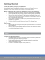
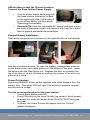
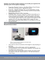
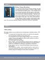
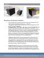
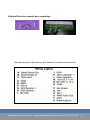
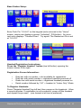
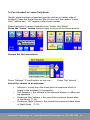
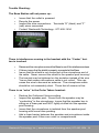
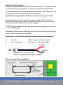
Installation Guide System Operating Instructions (Single Lane System) Wentworth Technology, | www.WentworthTechnology.com | 877.495.1634 1 Wentworth Technology, Inc.Inc. | www.WentworthTechnology.com | 877.495.1634 Table of Contents Getting Started ....................................................................... 3 Site Survey............................................................................... 3 Confirm the location of the Base Station.................................. 3 Connect the Base Station Power Supply................................. 4 Power On Headset ................................................................... 4 Test the proposed location for the base station........................ 4 Photo: Correct routing of cables to avoid radio interference with base antennae................................................................... 5 Mount the base station.............................................................. 5 Battery Charger Mounting......................................................... 6 Cable pulling............................................................................. 6 Microphone and Speaker Installation ...................................... 7 Vehicle Detector control box mounting...................................... 9 Instructions for wiring loop, detector board, microphone and speaker........................................................... 9 Base Station Setup.................................................................... 10 Headset Registration Instructions.............................................. 10 Volume Set Up Instructions........................................................ 11 Select the volume to be adjusted............................................... 11 Set Clock Instructions................................................................ 12 Night Volume Time Instructions.................................................. 13 Set Lane Configuration Instructions............................................ 13 Trouble Shooting.......................................................................... 14 Additional Installations................................................................. 16 Parts List..................................................................................... 17 Wentworth Technology, Inc. | www.WentworthTechnology.com | 877.495.1634 2 Getting Started Locate the battery charger and batteries. Immediately begin charging the batteries, as you will need to use a headset to test and confirm the location of the base station. When unpacking the system for installation, insure the following: ▪▪ Inspect the system for damage—Report to Wentworth immediately. ▪▪ Insure that all parts are present—Report missing parts immediately. ▪▪ Record the serial numbers IF the system is supplied from any other source than directly from Wentworth Technology. Send the #’s to Wentworth Technology. ▪▪ Insure that a detection system (loop and stand alone board) is installed or supplied. ▪▪ Confirm that the conduit does not carry AC voltage lines. Site Survey: ▪▪ Speak with the manager/owner/job superintendent to coordinate the installation. ▪▪ Discuss the proposed Base Station location. See below for detail on selecting a proper location. STEP 1 Location of the Base Station: ▪▪ The Base Station must be in a location easily accessed by restaurant personnel (eye level, within arm’s reach). ▪▪ Avoid signal blocking metal walls, heading equipment, areas where liquids could splash on base. ▪▪ Locate an available duplex outlet (within 6’) Wentworth Technology, Inc. | www.WentworthTechnology.com | 877.495.1634 3 USE the Base to test the Chosen Location. Connect the Base Station Power Supply: ▪▪ ▪▪ Plug the power supply barrel plug into the base station connector located on the upper right side. In the event of an out of box failure, call Wentworth Technology immediately. Precision Tip: Loop the removable AC power cord back across the body of the power supply and secure it with a zip-tie or black tape to prevent accidental disconnections. Headset Battery Installation: The battery compartment is located on the opposite side of the headset from the microphone boom. To open the battery compartment, push up on the battery door latch while pulling out the bottom of the door. Insert the battery with the label facing out. Replace the door by inserting the top of the door in its slot followed by pushing the bottom of the door into place until it locks. Power On Headset: Press the ORANGE button on the opposite side of the headset from the battery door. The green LED will light if the battery is properly inserted and the door is closed. Test the proposed location for the base station: ▪▪ Unlock Base Station with PIN ▪▪ Press PIN button on the Home Screen (top center of touch screen) to access the “enter pin” screen Enter Tech Pin“2580” using the key pad ▪▪ If correct, the Home Screen will appear with the “Unlock” graphic displayed. Wentworth Technology, Inc. | www.WentworthTechnology.com | 877.495.1634 4 Register the headsets (Note Headsets are usually pre-registered to the base prior to the system shipping): ▪▪ ▪▪ ▪▪ ▪▪ ▪▪ ▪▪ Press the “Register” button on the Base Station Touch Screen (TOP LEFT) to access the “registration screen”. Press the “Register Headset” bar on the Registration screen. Power the headset “ON” while remaining close to the base station. (One headset at at time). Registration will occur within 3 minutes. Precision Tip: Wearing a registered headset, physically go to areas where the headsets will be used and confirm that good communications are available. Static will indicate a low signal. “out of range” will be heard for loss of signal. Remember to test outside in the DT lane where Speed Team usage will occur. After testing, unplug the Base Station for the balance of the wiring connections. STEP 2 Mount the base station: Photo: Correct routing of cables to avoid radio interference with base antennae. ▪▪ ▪▪ ▪▪ Use a drill to oval out one hole in the hinger for easy leveling of the base. Depending on the surface type, select an appropriate mounting fastener (zinc wall anchors supplied) insuring that the mounting is firm and secure. Insert two screws into the Base Station hinge and spacer plate and attach to the wall. Spacer plate is 1”x3” with two holes to match hinge. Wentworth Technology, Inc. | www.WentworthTechnology.com | 877.495.1634 5 STEP 3 Battery Charger Mounting: It is recommended that the battery charger be wall mounted to prevent liquids, crumbs or other debris from entering the battery slots. The charger must be mounted vertically with the lights on the right side so that the battery slot latches are at the bottom of the slot to retain the battery. Use the supplied Velcro patches (one at each end) to secure the charger to the wall. Pull “feet” off the bottom of the charger if wall mounting. Use alcohol wipe to clean the mounting surface. Allow adhesive to cure. Do not mount battery chager to velcro for 24 hours if possible. STEP 4 Cable pulling: All audio cables are provided and are twisted-pair, shielded cables, 200’ in length. ▪▪ It is important that separate cables are used for the speaker and microphone located at the order point. ▪▪ It is important that no high-voltage wiring is run in the audio cables. This would negatively affect audio quality as well as violate the Electrical Code. ▪▪ Two wire spools are provided. ▪▪ Black Jacket, use the Red/Black internal wires for speaker connecion. The extra green and white strands in the black jacket cable are available for a detector connection if required. ▪▪ Gray Jacket, use the Green/White/Shield internal wires for microphone. ▪▪ After pulling the cables, allow enough length on each end to reach the intended areas plus a little extra wire to make connection easy, but leaving no coils when completed. Wentworth Technology, Inc. | www.WentworthTechnology.com | 877.495.1634 6 STEP 5 Microphone and Speaker Installation: ▪▪ ▪▪ ▪▪ The microphone should be mounted at a level where the customer will be speaking directly to it. (36”-40”) The speaker should be mounted below the microphone by 20” to 24” to avoid feedback Precision Tip: CAUTION: USE ONLY LIGHT PRESSURE TO HOLD THE MICROPHONE OR SPEAKER IN PLACE. Over packing the foam will reduce it’s noise canceling properties and will transmit vibration. Loose, rough cut foam is preferred! It is not necessary to fill the area around the speaker or microphone. However, if there is a compartment between the microphone and speaker, it is good to fill that area with any unused foam to reduce resonance in the speaker post. ▪▪ Precision Tip: Solder all wire connections. Leave wire connections pointed up so that water cannot follow the wire into the connection. Insure that wires do not lead water into the speaker box or microphone, i. e. the wire should come out of the bottom of the housing.Solder the microphone leads to the gray jacket cable, (white and green). ▪▪ Precision Tip: Do not ground the shield to the post! Leave shield un-attached! Shield will only be connected at the base station/terminal block. Solder the speaker leads to the black jacket cable (RED and BLK wires) Solder the loop leads to the Wentworth Technology, Inc. | www.WentworthTechnology.com | 877.495.1634 7 Vehicle Detector control box mounting: Standard Speaker, Microphone and Detector connections Illustration Wentworth Technology, Inc. | www.WentworthTechnology.com | 877.495.1634 8 STEP 6 Instructions for wiring loop, detector board, microphone and speaker: Precision Tip: All stripped wires should be tinned prior to attaching to the base station. ▪▪ “Loop In” If properly connected at the speaker/post/menu board the “loop in” uses the black cable/gree-white wires. Wentworth Technology, Inc. | www.WentworthTechnology.com | 877.495.1634 9 Base Station Setup: Enter Tech Pin “2-5-8-0” on the keypad (auto-returned to the “Home” screen, which now displays a green “Unlocked” PIN button). An incorrect entry displays “Thumbs Down”. Try again! The Restaurant Pin is set at “0-0-0-0”. Headset Registration Instructions: Press the “Register Headset” button (top left button) opening the screen shown to the right. Registration Screen Information: ▪▪ ▪▪ ▪▪ ▪▪ Gray bar with no number = slot available for registration Gray bar with serial number = registered headset powered off Green bar with serial number = registered headset powered on Serial number followed by “LO” = headset in “Listen Only” Mode To Register Headsets: Press “Register Headset”(top left bar) then power on the headsets. Allow a couple minutes. If registration is not successful, power off the headset and repeat the process. (one heaset at at time is preferred). Wentworth Technology, Inc. | www.WentworthTechnology.com | 877.495.1634 10 To Put a Headset in Listen Only Mode: Identify serial number on headset (see the sticker on battery side of headset) Press the Serial Number Bar (it turns red) then press “Listen Only” (yellow bar) “LO” appears after serial number. Repeat process to remove headset from “Listen Only Mode” Press the “Home” button (bottom right) to return to the Home screen. Volume Set Up Instructions: Press “Settings” (Fourth button on top row. ) Select the volume to be adjusted: ▪▪ ▪▪ ▪▪ ▪▪ Press “Set Volume” Inbound = sound from the order point microphone which is heard in the headset (4-6 generally) Grill Speaker = the volume of the optional kitchen or office ceiling speakers Outbound Day Volume = the sound the customer hears when in Day Mode (7-10) Outbound Night Volume = the sound the customer hears when in Night Mode (7-10) Wentworth Technology, Inc. | www.WentworthTechnology.com | 877.495.1634 11 Tips on setting the sound: For the best results, keep both inbound and outbound volumes as low as possible. Setting the Inbound volume too high will unnecessarily increase background noise. Begin setting at Level 3, increasing one step at a time until satisfactory. (3-6 most common). Setting the Outbound volume too high may produce echo. Begin setting at level 7. (If the Night Volume mode is NOT used, set that volume to match the DAY Volume. This provides protection from someone activating the Night Volume Mode accidentally). (7-10 most common). Grill Speaker Option: The Grill speaker must be balanced by adjusting the potentiometer on the circuit board inside the Base Station housing. Opening the left side cover will reveal two blue knobs. The upper blue knob is the Grill Speaker Balance adjustment. The knob can be rotated ¾ of a full turn, stop to stop. Test the setting until an acceptable balance is achieved between the volume of the customers voice (clockwise) and the volume of the order takers voice (counterclockwise). Press “Tools” (lower right, above “Home”) to return to the previous screen. Set Clock Instructions (optional- for greeter or night volume only): Press “Set Clock” opening screen to the right. Adust the time (24 hour format) using the arrows above or below the numbers. Press “Tools” to return to the previous screen. Press “Set Night Volume Time” Wentworth Technology, Inc. | www.WentworthTechnology.com | 877.495.1634 12 Press “Set Night Volume Time” opening the screen to the right. Night Volume Time Instructions: If Night Volume Mode is NOT used. Set all times to 00:00. If Night Volume Mode WILL be used: Touch “Begin Time” then set the time desired for a sound reduction to occur. Touch “End Time” and set the time for the standard Day Volume to return. Night Volume Mode provides an automatic daily change of volume to accommodate locations where residential areas are close to the restaurant. Be sure to properly set the desired Night Volume level on the “Set Volume” screen. Press “Tools” to return to the previous screen. Set Lane Configuration Instructions If this location has multiple lanes Press “Set Lane Configuration” (Default is Single Lane) If the site does not have multiple lanes, Press “Home” and set up is complete. Press the appropriate lane configuration as illustrated by the graphics. The “selection” is always the illuminated button. Press “Home”. Set up is complete. Wentworth Technology, Inc. | www.WentworthTechnology.com | 877.495.1634 13 Trouble Shooting: The Base Station will not power up: ▪▪ ▪▪ ▪▪ ▪▪ Insure that the outlet is powered. Recycle the power Inspect the wire connections: Terminals “E” (black) and “F” (red) wires connected. Contact Wentworth Technology: 877-495-1634 There is interference coming in the headset with the “Center” button is touched: ▪▪ ▪▪ ▪▪ ▪▪ Disconnect the microphone wire at the Base to see if the interference stops. If it does, insure that the shield is properly connected at the Base Insure that the shield is not connected at the microphone end of the cable. Never connect the shield to the speaker post housing! The terminal may be tightened on the insulation instead of the wire. *Insure that excess microphone cable is not coiled. This can cause the wire to become an antenna. The microphone cable should be cut reasonably short. Three feet of excess is fine. There is an “echo” in the Order Takers headset: ▪▪ ▪▪ ▪▪ ▪▪ Reduce the Outbound Volume setting. Inspect the speaker post. Sound from the speaker may be “conducting” to the microphone. Insure that the speaker box is sitting on a foam pad and NOT tightly stuffed into the speaker post housing. Insure that the microphone is isolated from the speaker post housing with loose foam packing. Add a foam barrier between the speaker and microphone inside the speaker post if there are voids or compartments. Wentworth Technology, Inc. | www.WentworthTechnology.com | 877.495.1634 14 There is a lot of ambient noise in the headset when the “Center” button is touched: ▪▪ Reduce the Inbound Volume setting review settings to Night Volume Time. One headset will not communicate with the speaker post: ▪▪ ▪▪ ▪▪ ▪▪ ▪▪ Power off the headset. Listen to the voice prompts Is the headset registered and connected? (View the Registration screen.) Is the serial number showing? Is the headset in Listen Only Mode? Delete then Register the headset. The buttons on one headset will not work: ▪▪ ▪▪ Power off and on Check registration. Delete and register again. The detector is not working: ▪▪ ▪▪ ▪▪ ▪▪ ▪▪ Inspect all detector and loop wiring and connections Insure that the “common” is connected to terminal “O-GND” Insure that the “Normally Open” is connected to terminal “MVEH DET in 3V” Recycle the power to the detector, insuring that no cars are present. Test the continuity of the loop. If a direct short is showing, the loop is defective. Wentworth Technology, Inc. | www.WentworthTechnology.com | 877.495.1634 15 Additional Installations: Kitchen speakers (grill speakers) are an optional item. If ordered, install as directed by the manager/GC or owner in the kitchen drop ceiling. It is important that the kitchen speakers be located as far away from the areas frequented by headsets to reduce feedback. SpeedThru to HyperActive Q-Timer connection for greet cancel The HyperActive Q-Timer requires a special cable (P/N 3172) from Wentworth Technology in order to utilize the greet timer function when using Wentworth’s SpeedThru headset system. DO NOT use a standard audio jack/cable, this will damage the Q-Timer or the WT SpeedThru. Wentworth Technology’s audio jack for the Q-Timer has special circuitry in it to make the devices compatible. Connection Instructions: Speedthru Base Station wiring legend J K Ground Menu Speaker + Black wire from Q-Timer cable Red wire from Q-Timer cable Saw Cut Loop Wire Installation Wentworth Technology, Inc. | www.WentworthTechnology.com | 877.495.1634 16 Inspect the cut ◦Check the depth (1-1/4” to 1-1/2” minimum) ◦Clean any debris from the bottom of the slot ◦“Knock down” sharp corners to prevent damage to the wire insulation Lay the wire ◦Start at the speaker/ menu board allowing enough wire to make final connections ◦Follow the lead wire slot to the main body of the loop ◦Lay 5 or 6 turns of wire around the loop ◦Use a NON-METAL push stick with rounded corners to seat the wire in the slot as each turn is laid in place ◦Keep tension on the wire to prevent kinks/humps in the stack ◦Return out the lead slot to the speaker post or menu board Seat the wire ◦Use 4” pieces of backer rod foam every couple feet to hold the wire in the slot ◦Later, the sealant will be able to flow to the bottom of the slot encasing the wire Twist the lead ◦Anchor the wires at point they enter the lead slot ◦Chuck the ends of the wire in a drill and give the lead wire 15-20 twists per foot ◦The splice connections must be soldered to avoid corrosion of the wire ◦IMPORTANT: Twisting the wire is to insure that one wire does not move in relation to the other resulting in a false detection. Cut the tail reasonably short and splice it to the jacketed wire. Wrap the splice with electrical tape to avoid movement in the wires. Seal the saw cut ◦Re-check the wire in the body of the loop to insure it is seated ◦Fill the slot half full on the first pass ◦Hot pavement may make the sealant bubble, so allow a cure time before filling slot ◦Seal the full length of all saw cuts to prevent water from entering the cut Wentworth Technology, Inc. | www.WentworthTechnology.com | 877.495.1634 17 A Greet Cancel Out Switch closure to ground for greet cancel B Greet Enable In Input from greeter to trigger greet, 3V pullup, ground to activate. Typically shorted to the detector board C Timer Alert Input for timer system alert in headset, 3V pullup, ground to activate (Customer waiting) D Ground Ground for “C” E Ground Ground for “F” F 12V Power In 12V Power input from DC transformer G Grill Speaker + Grill or Office monitor speaker positive connection H Grill Speaker - Grill or Office monitor speaker negative connection I Ground Ground spare J Ground Ground spare K Menu Speaker + Menu Board speaker positive connection L Menu Speaker - Menu Board speaker negative connection M Vehicle Det In 3V Menu Board Vehicle Detector input (3V pullup) Pull to Ground “O” to activate N Vehicle Det In 12V Menu Board Vehicle Detector input (12V pullup) Pull to Ground “O” to activate O Ground Ground for “M” or “N” connect to common ground for vehicle detectors P Microphone Shield Menu Board Microphone shield connection Q Microphone - Menu Board Microphone negative connection R Microphone + Menu Board Microphone positive connection S RMS Audio Out Line Level output—for record function T Ground Ground for “S” and “U” U Greet Audio In Greeter Audio line level in from timer/ greeter Wentworth Technology, Inc. | www.WentworthTechnology.com | 877.495.1634 18 Parts List: Base station: ▪▪ Three (3) screws #6 ▪▪ Three (3) wall anchors (EZ Ancor metal) ▪▪ Template for marking base station screw locations ▪▪ Cord restraint for power cord and wires (velcro and zip ties) ▪▪ Attached hinge and loose magnetic catch ▪▪ Gray wire nuts for detector connection Wire: ▪▪ Two (2) 200’ spools of 22 AWG Shielded, one black jacket, one gray jacket Speaker/Microphone: ▪▪ Enclosure for speaker ▪▪ Microphone Enclosure Foam ▪▪ 6 silicone filled wire nuts ▪▪ 8” x 8” x3/8 wind screen (2 included) plus white water proof fabric (2) ▪▪ Acoustic foam for speaker post Vehicle Detector (if included): ▪▪ Screws (2) ▪▪ Anchors (2) Battery Charger: ▪▪ Mounting Velcro (2 pcs) Headsets: ▪▪ Hooks for storage- 1 per headset ▪▪ Screws/anchors- 2 per hook Wentworth Technology, Inc. | www.WentworthTechnology.com | 877.495.1634 19 Basic Detector Wiring Most detector boards are quite similar in operation, having the following connections: •A pair of loop inputs which connect to the in-ground loop •A pair of relay outputs which connect the to base station •A pair of power inputs or a barrel plug from a transformer (generally 12VDC to 24VDC) •A secondary pair of relay outputs for a standalone timer (optional) Important points: •Soldering of loop connections it CRITICAL. Corrosion will result in missed detections. •Vibration or movement between the loop wires and loop extension can result in false detections which is why loop wires are twisted. Further secure all loose loop wires and extension with electrical tape to insure they do not move in relationship to each other. •Insure the 3V and Ground connections are identified and properly connected at the Base Station. Failure to do so could possible cause difficulty if a timer is ever added to the system. Wiring EDI LMA 0200 Dectector w/11 pin Block Wentworth Technology, Inc. | www.WentworthTechnology.com | 877.495.1634 20 Base Connection “M” 3V must be to the 6-Output A Relay- N.O. from the detector board. Base Connection “P” Mic Shield is the raw shield in the gray jacket cable. Shield must not be connected at the speaker post or it will induce hum. No other connections are sensitive to + or – polarity LOOP: It is important that the loop lead wires are twisted to prevent movement and connections are soldered. This includes all wire from the loop to the detector board orange/red wires. Movement can cause false detections. Tape wires together after soldering. “B” relay (detector pins 3 N.0. & 9 COM) may be used for a stand alone timer. NOTE: When the “B” relay is used Dip switch “7” must be switched to “ON”. Wentworth Technology, Inc. | www.WentworthTechnology.com | 877.495.1634 21 Wiring EDI LMA 0200 Detector w pigtail Base Connection “M” 3V must be to the blue wire (6-Output A RelayN.O.) from the detector board. Base Connection “P” Mic Shield is the raw shield in the gray jacket cable. Shield must not be connected at the speaker post or it will induce hum. No other connections are sensitive to + or – polarity LOOP: It is important that the loop lead wires are twisted to prevent movement and connections are soldered. This includes all wire from the loop to the detector board orange/red wires. Movement can cause false detections. Tape wires together after soldering. “B” relay (detector pins 3 & 9) may be used for a stand alone timer. NOTE: When the “B” relay is used Dip switch “7” must be switched to “ON”. Wentworth Technology, Inc. | www.WentworthTechnology.com | 877.495.1634 22 Wentworth Technology, Inc. | www.WentworthTechnology.com | 877.495.1634 23 Wentworth Technology, Inc. | www.WentworthTechnology.com | 877.495.1634 24 77 Industrial Park Road. Saco, ME 04072 www.wentworthtechnology.com 877.495.1634 ©2013. Part #3139 Rev 9_G Wentworth Technology, Inc. | www.WentworthTechnology.com | 877.495.1634 25 Wentworth Technology, Inc. | www.WentworthTechnology.com | 877.495.1634 26