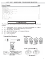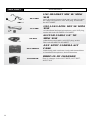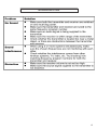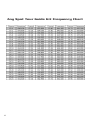
1
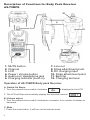
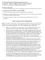
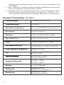
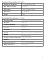
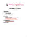
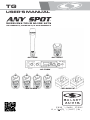
TG USER'S MANUAL ® TG-H2BPR-4, TG-BPTR-4, & ALS-RMBPR-4 MAKERS OF THE ORIGINAL HOT SPOT PERSONAL MONITOR This symbol indicates that dangerous voltage constituting a risk of electric shock is present within this unit. This symbol indicates that there are important operating and maintenance instructions in the literature accompanying this unit. WARNING! USING THIS SYSTEM AT EXCESSIVE VOLUMES CAN CAUSE PERMANENT HEARING DAMAGE. USE AS LOW A VOLUME AS POSSIBLE. In order to use this system safely, avoid prolonged listening at excessive sound pressure levels. Please use the following guidelines established by the Occupational Safety Health Administration (OSHA) on maximum time exposure to sound pressure levels before hearing damage occurs. 90 dB SPL at 8 hours 95 dB SPL at 4 hours 100 dB SPL at 2 hours 105 dB SPL at 1 hour 110 dB SPL at ½ hour 115 dB SPL at 15 minutes 120 dB SPL — avoid or damage may occur It is difficult to measure the exact Sound Pressure Levels (SPL) present at the eardrum in live applications. In addition to the volume setting on the Personal Monitors, the SPL in the ear is affected by ambient sound from floor wedges or other devices. The isolation provided by the fit of quality earpieces is also an important factor in determining the SPL. Here are some general tips to follow in the use of this product to protect your ears from damage. • Turn up the volume control only far enough to hear properly. • Ringing in the ears may indicate that the gain levels are too high. Try lowering the gain levels. • Have your ears checked by an audiologist on a regular basis. If you experience wax buildup in your ears, stop using the system until an audiologist has examined your ears. • Wipe the ear molds with an antiseptic before and after use to avoid infections. Stop using the earphones if they are causing great discomfort or infection. ! IMPORTANT SAFETY INSTRUCTIONS ! 1. 2. 3. 4. 5. 6. 7. READ these instructions. KEEP these instructions. HEED all warnings. FOLLOW all instructions. DO NOT use this apparatus near water. CLEAN ONLY with dry cloth. DO NOT block any ventilation openings. Install in accordance with the manufacturer's instructions. 8. DO NOT install near any heat sources such as radiators, heat registers, stoves, or other apparatus (including amplifiers) that produce heat. 9. DO NOT defeat the safety purpose of the polarized or grounding-type plug. A polarized plug has two blades with one wider than the other. A grounding type plug has two blades and a third grounding prong. The wider blade or the third prong are provided for your safety. If the provided plug does not fit into your outlet, consult an electrician for replacement of the obsolete outlet. 10. PROTECT the power cord from being walked on or pinched, particularly at plugs, convenience receptacles, and the point where they exit from the apparatus. 11. ONLY USE attachments/accessories specified by the manufacturer. 12. USE only with a cart, stand, tripod, bracket, or table specified by the manufacturer, or sold with the apparatus. When a cart is used, use caution when moving the cart/apparatus combination to avoid injury from tip-over. 13. UNPLUG this apparatus during lightning storms or when unused for long periods of time. 14. REFER all servicing to qualified service personnel. Servicing is required when the apparatus has been damaged in any way, such as power-supply cord or plug is damaged, liquid has been spilled or objects have fallen into the apparatus, the apparatus has been exposed to rain or moisture, does not operate normally, or has been dropped. 15. DO NOT expose the apparatus to dripping and splashing. DO NOT put objects filled with liquids, such as vases, on the apparatus. 16. Remove the batteries from the receiver if the system will not be used for a long period of time. This will avoid any damage resulting from a defective, leaking battery. 17. DO NOT throw used batteries into a fire. Be sure to dispose of or recycle used batteries in accordance with local waste disposal laws. LICENSING INFORMATION THIS RADIO EQUIPMENT IS INTENDED FOR USE IN PROFESSIONAL ENTERTAINMENT AND SIMILAR APPLICATIONS. Changes or modifications not expressly approved by Galaxy Audio Incorporated could void your authority to operate the equipment. Licensing of Galaxy Audio wireless microphone equipment is the user's responsibility, and licensability depends on the user's classification and application, and on the selected frequency. Galaxy Audio strongly urges the user to contact the appropriate telecommunications authority concerning proper licensing, and before choosing and ordering frequencies. NOTE: THIS EQUIPMENT MAY BE CAPABLE OF OPERATING ON SOME FREQUENCIES NOT AUTHORIZED IN YOUR REGION. PLEASE CONTACT YOUR NATIONAL AUTHORITY TO OBTAIN INFORMATION ON AUTHORIZED FREQUENCIES FOR WIRELESS MICROPHONE PRODUCTS IN YOUR REGION Licensing: Note that a ministerial license to operate this equipment may be required in certain areas. Consult your national authority for possible requirements. Table of Contents Page 1. Safety ..................................................................................... Inside front cover 2. Contents .......................................................................................................... 1 3. Introductions .................................................................................................... 2 4. AS-TVH2 Compact Handheld .......................................................................... 3 5. AS-TVBPT Pendant ......................................................................................... 5 6. AS-TXRM Tabletop Transmitter ....................................................................... 6 7. AS-TVBPR Receiver ...................................................................................... 8 8. Tour Guide Setup Procedure ....................................................................... 9 9. Unit Specifications ....................................................................................... 10 10. Accessories ................................................................................................. 14 11. Troubleshooting ........................................................................................... 15 12. Frequency Chart .......................................................................................... 16 13. Certification ................................................................................................... 17 CONTENTS: The following items are included in the Any Spot Wireless Tour Guide system: 1. 2. 3. 4. 5. (1) - Transmitter of your choice: AS-TVH2 Handheld, AS-TVBPT Pendant, or AS-TXRM Tabletop Transmitter (4) - AS-TVBPR Receivers (2) - AS-DCBPTR Drop In Charging Stations (1) - Owner's Manual (1) - Carrying Case Transmitter Choices: Receivers: Drop Load Chargers: 1 GALAXY AUDIO ANY SPOT WIRELESS TOUR GUIDE SYSTEMS Introduction The Tour Guide Systems are a lightweight, multi-channel wireless system that can be used in museums, conference rooms, churches, hotels, manufacturing plants, and by rental and production houses. Since the Tour Guide system operates in the UHF band, this kit can allow for a speech or presentation to be translated into another language and broadcast to listeners. It can also be used in loud or noisy environments for tours of manufacturing plants and facilities. The Tour Guide system can be used with your choice of the ASTVH2 handheld microphone, AS-TVBPT Pendant transmitter, ASTVMBP body pack transmitter with a headset or lavalier mic, or the AS-TXRM Table Top transmitter. The AS-TVBPT Pendant has a builtin microphone, and comes with a removable lanyard and belt clip for hands-free operation. The AS-TXRM Table Top transmitter gives users the ability to send a signal directly from a mixing board, or other device, to the listeners. The AS-TVBPR receivers are lightweight (3.2 oz.) with easy turn on/off volume knob. The backlit LCD screen allows for easy visibility of the channel settings and battery life. The receiver also comes with a removable lanyard and belt clip for hands free operation. 2 Description of Functions for Handheld Microphone AS-TVH2 MUTE Battery Cover HI LOW RF Power slider switch MUTE/TALK Option slider switch Power Bottom of Hand Held Channel Adjustment Charging contacts Operation of Handheld Microphone AS-TVH2 A. Battery Installation Steps: 1. Turn off the microphone before inserting batteries. 2. Press in the latch to release the battery cover and pull it away from the unit. 3. Insert 2 disposable batteries of 1.5V type or 2 rechargeable batteries of 1.2V type. 4. Observe proper polarity while inserting batteries. 5. Slide the battery cover back to its original position. 3 B. Switch-On Steps: 1. Press the power switch and hold for about two seconds until the LED turns to Blue and is displayed in the LCD. 2. The LCD will then automatically display the selected channel. :Channel indicator. C. Switch Off steps: 1. Press and hold power switch for about two seconds until the LCD displays D. Channel/Frequency Settings (with power on): 1. Press the Channel adjustment button in and hold for about 3 seconds. 2. The Channel number display will start flashing. 3. Press the Channel adjustment button to the right to display a higher numbered channel. 4. Press the Channel adjustment button to the left to display a lower numbered channel. 5. Press the Channel adjustment button in to activate the selected channel. E. Power Settings: 1. Remove battery cover and batteries, the switch is under the batteries. HI LOW RF POWER TALK PUSH TALK F. Mute options 1. Remove battery cover and batteries, the switch is under the batteries. 2. With the switch in the talk position the microphone is on until you press the mute button. 3. With the switch in the Push position the microphone is muted until you press and hold the mute button. 4. In either position, when the mute switch is green the microphones is on, when the mute button is red the microphone is muted. G. LCD Indications: 1. :Three bars means batteries are fully charged. 4 2. :One bar indicates low batteries. Replace or recharge the batteries. 3. :No bars showing indicates batteries are exhausted and after flashing three times the power will automatically shut off. Description of Functions for Body Pack Transmitter AS-TVBPT 10 8 5 6 4 7 11 9 1 2 12 3 1. POWER / MUTE button 2. Channel / Volume button 3. LCD 4. Mesh Screen Cover (microphone) 5. External mic. Input - 3.5mm 6. Charging indicator (built-in) 7. Aux input 8. Strap attachment point 9. DC charging input 10. Strap attachment point 11. Belt clip 12. Charging terminal Operation of AS-TVBPT Transmitter A. Switch-On Steps: 1. Press the power switch and hold for about two seconds until the LED turns to Blue and is displayed in the LCD. 2. The LCD will then automatically display the selected channel. B: Volume adjust 1. Press the + button to increase press the – button to decrease. The range is 3 steps 5 C. Channel/Frequency Settings (with power on): 1. Press the Set button in and hold for about 3 seconds. 2. The Channel number display will start flashing. 3. Press the + button to display a higher numbered channel. 4. Press the - button to display a lower numbered channel. 5. Press the set button to activate the selected channel. D. Switch Off steps: 1. Press and hold power switch for about two seconds until the LCD displays AS-TXRM Tabletop Transmitter The AS-TXRM is a stand alone version of our AS-TVTX Audio Link Transmitter module. The module is housed in a standard half-rack sized enclosure, and includes a variety of inputs and outputs as well as mixing controls. The AS-TXRM is great for transmitting the entire mix from a mixing console to one or more Traveler speakers equipped with wireless receivers. Front Panel 1 2 3 4 5 6 7 8 9 10 Rear Panel 11 12 13 14 1. Power Switch w/ LED 2. Mic Volume 3. Mic On/Off Switch 4. Mic On LED 5. Aux Volume 6. Aux On/Off Switch 7. Aux On LED 8. Transmitter Module 9. Headphone Volume 6 15 16 17 18 10.Headphone Output 11. Antenna Connector 12. L/R Aux Outputs 13. L/R Aux Inputs 14. Balanced Mic Input 15. 5v DC Mic Switch 16. Unbalanced Mic Input 17. 12-15v DC Output 18. 12-15v DC Input Setup and Operation of AS-TXRM 1. 2. 3. 4. 5. 6. 7. 8. Starting with both the main power switch off (1) and the transmitter (8) power switch off, plug the included power supply into the DC In jack (18), and then plug the other end into an AC outlet. Connect the supplied antenna to the Antenna Jack (11). Set all volume controls (2), (5), & (9) to the minimum. Set the input TX switches (3) and (6) to off, and then switch on the power (1). Connect the desired source devices (such as a microphone or line output of a mixer) to the appropriate AS-TXRM inputs. The XLR input (14) will accept balanced mic level signals. The ¼" input (16) will accept unbalanced mic level signals, and provide 5v DC to condenser mics when desired, by activating the switch (15). These two inputs are controlled by the Mic Volume (2) and TX switch (3). The L/R Aux Inputs will accept a stereo line level signal, and are controlled by the Aux Volume (5) and TX switch (6). When the TX switches (3) and (6) are engaged, the respective LEDs (4) and (7) will light, indicating that the input signal is being sent to the Transmitter Module (8) and the L/R Aux Output jacks. Switch on the Transmitter Module (8) and set it according to the Audio Link System instructions provided on page 13. Set the receiver(s) according to the Wireless Mic Receiver instructions provided on page 12. Start sending a signal from the source device and set various volume controls (in the signal chain from the source to the receiving device) to the desired levels. It is important to set the gain structure properly to achieve the best signal to noise ratio. Normally you will want to set the output of the source as high as possible without causing distortion to the input of the following device, and so on down the line. Signals sent to the L/R Aux Input will appear at the Headphone Jack (10) and be controlled by the Phone Volume (9). Note: Signals from the Mic Inputs (14) and (16) do not appear at the Headphone Jack. The DC Output Jack (17) supplies 12v DC for charging or powering other devices. Make sure any device connected to this jack complies with the voltage and current rating listed for this jack. 7 Description of Functions for Body Pack Receiver AS-TVBPR 10 8 5 6 7 4 11 9 1 2 12 3 1. MUTE button 2. Channel 3. LCD 4. Power / Volume button 5. Audio out / Headphone jack 6. Charging indicator (built-in) 7. Line out 8. Strap attachment point 9. DC charging input 10. Strap attachment point 11. Belt clip 12. Charging terminal Operation of AS-TVBPR Body pack Receiver A. Switch-On Steps: 1. Turn the power/volume switch clockwise is displayed in the LCD. 2. The LCD will then automatically display the selected channel. B: Volume adjust 1. Turn the power/volume switch clockwise to increase, turn counter clockwise to decrease. C: Mute 1. Press the mute button, it will turn red to indicate mute. 8 D. Channel/Frequency Settings (with power on): 1. Press the + button to display a higher numbered channel. 2. Press the - button to display a lower numbered channel. 3. Press the set button to display the frequency. E. Switch Off steps: 1. Turn the power/volume control completely counter clockwise until it clicks off. F. Charging the AS-TVBPT and AS-TVBPR 1. These units have permanent rechargeable lithium batteries. 2. Plug the provided charger into the body pack and an AC power source when the battery display shows empty. 3. An optional cradle charger that will charge two body packs at a time is available. Note: The word “Transmitter” in this procedure applies to either the AS-TVHH Handheld, AS-TVH2 Handheld, AS-TVBPT Pendant, AS-TVMBP Body Pack with its connected Microphone, or the AS-TXRM Tabletop Transmitter. 1. Make sure that both the Transmitter and AS-TVBPR Receiver power switches are in the off position before beginning this procedure. 2. Receiver: Attach headphones to the Green headphone jack. Move the power switch to the ON position. The LED indicator should illuminate Red for a few seconds and then go out. If the LED lights up Green, first double check that the Transmitter power switch is in the off position. If the LED remains Green even when the Transmitter is switched OFF, adjust the channel switch until the LED goes out. This will greatly increase the likelihood that the Any Spot system will be functioning on a frequency free from interference. 3. Transmitter: Adjust the channel switch to match the channel setting selected on the AS-TVBPR. Move the Transmitter power switch to the ON position. The Red low battery indicator on the Transmitter should flash on and then go out. The LED on the AS-TVBPR should now illuminate Green, indicating that it is receiving signal from the Transmitter. If the LED on the AS-TVBPR does not turn Green, verify that the Transmitter and AS-TVBPR have both been adjusted to the same channel settings. If the AS-TVBPR LED still does not turn Green, please try selecting a new group and channel on both the Transmitter and AS-TVBPR to avoid any possible interference from outside RF sources. Repeat this until the AS-TVBPR LED turns Green. 4. If using the AS-TVMBP Transmitter, verify that the switch on the back of the body pack is set to "Mic". Increase the headphone volume control on the AS-TVBPR slowly while speaking into the Microphone and listening to the Headphones. If you are not hearing any audio or just a low level signal, try increasing the Gain control (turn clockwise) on the AS-TVMBP until a proper level is reached. If the audio sounds 9 distorted, try decreasing the Gain control (turn counter-clockwise) on the AS-TVMBP. 5. Once a frequency has been selected, additional Receivers may be set to the same frequency and audio quality verified. 6. A general rule for any wireless system: Any number of Receivers may be set to the same frequency and used in the same area. However, only one transmitter may be used on a selected frequency in any given area. Pendant Transmitter (AS-TVBPT) 10 Oscillation type PLL Synthesized control OSC Frequency Range 640~664 MHz Selectable Frequencies Pre-programmed 96 switchable frequencies Microphone Electrical Condenser RF Power Hi: below 10 dBm and Low: 4± 2 dBm Max. Modulation ±80 kHz, with level limiting T.H.D < 1% @ f = 1 kHz, MIC IN = -30 dBv AUX Modulation level 7 ± 0.5 kHz @level=-20 dBv, f=1 kHz. MID Tone Frequency / Modulation 38 kHz / 2.5 ± 0.5 kHz. S/N >60 dB @ with AS-TVBPR, f = 1 kHz, MIC IN = -30 dBv Operating Range Hi: > 50 M, Low: >30 M @ with AS-TVBPR, Open Field face to face Frequency Response Aux 70 Hz ~ 12 kHz Mic 100 Hz ~ 12 kHz Mic 70 Hz ~ 12 kHz Batter y Li-ion 3.7V 1200 mAh DC Current Hi power: 85 ± 10 mA; Low Power: 65 ± 10 mA @ 3.7 V Batter y life Hi power up to 12 hours Low power: up to 16 hours Pendant Transmitter (AS-TVBPT) Batter y full charge time 3 ~ 4 hours @1200 mAh Type. MIC / AUX in connector 3.5 mm jack LCD display Channel, Frequency, Battery. Dimensions 88 x 52 x 34 mm Weight 75 kgs Handheld Microphone (AS-TVH2) Microphone type Uni-Directional Condenser 16.5mm Element RF output 10mW/1mW Frequency Response 70Hz-16kHz Channels 16 or 96 Indicators Power, Mute/Talk Display Back Lit LCD (Channel, 3 bar battery indicator) Batter y 2- AA type (Ni-MH 1600 mAh) Rechargeable battery 1.5V 2- AA Alkaline disposable Batter y life Alkaline disposable 12 to 16 hours typical Antenna Built-in Dimensions ( Dia x L ) 1.16" x 7.9" (37 x 200 mm) Weight with batter y .20 oz. (90.7 g) 11 Tabletop Transmitter (AS-TXRM) 12 RF output 10mW Spurious emission Less than 250 nW Display status LCD indicator displays channel or frequency Channel select SET, UP, DOWN keys Antenna Built-in or external Dimensions ( L x W x H ) 8.27" x 8.46" x 1.97" (210 x 215 x 50 mm) Weight 2.8 lbs (1.26 kg) Bodypack Receiver (AS-TVBPR) Model no. AS-TVBPR Frequency Range UHF 640~664 MHZ Selectable Frequencies Pre-programmed 96 switchable frequencies Case Plastic Oscillator PLL synthesized Receiving Mode PLL Single channel Sensitivity Sinad > 20 dB @ Ear.out:500 mV, RF=-105 dBm, f=1 kHz, Mod=14 kHz. AUX output level @ 1kΩ 300 mV 2RF=-60 dBm, f=1 kHz, Mod=14 kHz Ear. output level 1.4V @ VR max., RF=-60 dBm, f=1 kHz, Mod=14 kHz. <1% @ Ear.out:500mV, RF=-60 dBm, f=1 kHz, Mod=14 kHz. Ear. output T.H.D. S/N >60 dB @ with AS-TVBPR, f=1 kHz, MIC IN = -30 dBv Frequency Response - Aux 70 Hz ~ 12 kHz @with AS-TVBPR Aux Frequency Response - Ear. 100 Hz ~ 12 kHz @with AS-TVBPR Mic Tone Squelch Frequency 38 kHz. Operating Range Hi: > 50 M, Low: >30 M Earphone & AUX out 3.5 mm TRS Built-in speaker 8Ω/1W Batter y Li-ion 3.7 V 1200 mAh. Batter y life. up to 18 hours Batter y full charge time 3 ~ 4 hours LCD display Channel, Frequency, Battery Dimensions 36 x 52.3 x 99 mm (DxWxH) Weight 100 g Design and specifications are subjects to be changed without notice. 13 ACCESSORIES omni directional heaset (dual ear) can also be used as a lapel microphone, mini XLR plug, works with the AS-TVMBP uni directional lav/lapel microphone, mini XLR plug, works with both AS-MBP5 & AS-MBP7 guitar/instrument cable, mini XLR plug, works with both AS-MBP5 & AS-MBP7 Holds body pack receivers, body pack transmitters or handheld microphone, and accessories. Drop in charger for the AS-TVBPR, AS-TVBPT, & AS-TVH2 14 TROUBLESHOOTING 15 16 Certification AS-TVBPR: Approved under the Declaration of Conformity (DoC) provision of FCC Part 15. Meets essential requirements of European Union R&TTE Directive 1999/5/EC, eligible to bear CE marking. Type approved to EN 300 422 -2. Meets requirements of EMC Standard EN 301 489 Parts 1 and 9. This Radio Equipment is intended for use IN MUSICAL PROFESSIONAL ENTERTAINMENT AND SIMILAR APPLICATIONS. NOTE: This Radio apparatus may be capable of operating on some frequencies not authorized in your region. Please contact your national authority to obtain information on authorized frequencies for wireless microphone products in your region Licensing: A ministerial license to operate this equipment may be required in certain areas. Consult your national authority for possible requirements. FCC Statement. The AS-TVBPR Receiver complies with Part 15 of the FCC rules. Operation is subject to the following two conditions: (1) this device does not cause harmful interference, and (2) this device must accept any interference received, including interference that may cause undesired operation. Licensing Statement. A user license may be required for operation. Contact the communications authority in your country for more information. Modifications to Approved Equipment. Changes or modifications not expressly approved by Galaxy Audio Incorporated could affect compliance with telecommunications standards, thereby voiding the user's authority to operate this product. NOTE: This equipment has been tested and found to comply with the limits for a Class B Digital Device, pursuant to Part 15 of the FCC Rules. These limits are designed to provide reasonable protection against harmful interference in a residential installation. This equipment generates, uses and can radiate radio frequency energy and, if not installed and used in accordance with the instruction may cause harmful interference to radio communication. However, there is no guarantee that interference will not occur in a particular installation. If this equipment does cause harmful interference to radio or television reception, which can be determined by turning the equipment off and on, the user is encouraged to try to correct the interference by one or more of the following measures: Reorient or relocate the receiving antenna. Increase the separation between the equipment and receiver. Connect the equipment into an outlet on a circuit different from that to which the receiver is connected. Consult the dealer or the Galaxy Audio Service Department for help. 17 THREE YEAR LIMITED WARRANTY WARRANTY Information can be viewed online at http://www.galaxyaudio.com/warranty.php ANY SPOT TOUR GUIDE KIT USER'S MANUAL Specifications in this manual are subject to change without notice. For the most up to date manual and information visit www.galaxyaudio.com. 1-800-369-7768 www.galaxyaudio.com © Copyright Galaxy Audio 2013 Printed in the U.S.A. V10032013