1
EN54 & ISO 7240 2- 8 Zone
Conventional Fire Control
Panel
Installation, Commissioning &
Configuration Manual
997-492-000-4, Issue 4.0
For use with NFS 2-8 and FLS 2-8 Fire Control Panels
EN54 & ISO 7240 2-8 Zone Conventional Fire Panel - Installation & Configuration Manual
The following markings are used either on
the panel hardware or in the documentation.
They have the following meaning:
WARNING:
Risk of electric shock.
Before working on mains
connections, ensure mains
power supply to the panel
is disconnected.
CAUTION:
Refer to the accompanying
documentation. (When
used in the documentation,
this marking is normally
associated with additional
instructions).
CAUTION:
!
EN54
ISO 7240
Contents
1
Introduction
1.1
1.2
Manual Purpose ..............................................
System Design & Planning ..............................
1.2.1 Personel .....................................................
1.3 General ...........................................................
1.4 CE Marking .....................................................
1.5 EN54 & ISO 7240 Functions ...........................
1.6 Ancillary Functions ..........................................
1.7 Related Documents .........................................
1.8 Warnings & Cautions ......................................
2
Failure to comply with the
requirements of EN54 (and
ISO 7240) is possible if warning
is ignored. The relevant
clause reference is stated.
Installation Guide
2.1
2.2
How to Use this Guide ....................................
Pre-installation Check List ...............................
2.2.1 Some Panel DO’s and DON’Ts ..................
2.3 Transient Protection ........................................
2.4 Product Inspection ..........................................
2.4.1 Checking Your Panel for Damage ..............
2.4.2 What to do if Your Panel is Damaged ..............
2.5 Installation Preparation ...................................
2.5.1 Removing the Cover ..................................
2.5.2 Back Box Fixing .........................................
2.6 Optional Equipment .........................................
2.6.1 2-Way Relay PCB ......................................
2.6.2 8-Way Relay PCB ......................................
CAUTION: Heat Hazard
Under
certain
fault
conditions PCB areas
identified by this symbol
may
reach
high
temperatures.
1
1
1
1
2
3
4
4
4
3
5
5
5
6
7
7
7
8
8
8
9
9
9
Cabling
3.1
Cabling Instructions ...................................... 10
3.1.1 Cable Terminations ................................... 11
3.2 Quality of Cable and of Cable Installation ........... 11
3.3 EMC Considerations ..................................... 12
3.4 Cables for Sounder Circuits .......................... 12
4
Field Devices
4.1
5
End-of -Line Devices ..................................... 13
Panel Electronics
5.1
5.2
5.3
6
Main PCB ...................................................... 14
PSU PCB ...................................................... 15
Label Inserts ................................................. 15
Commissioning
6.1
6.2
i
Introduction ...................................................
Preliminary Checks .......................................
6.3 External Wiring ........................................
6.3.1 Zone Wiring - New Installation .................
6.3.2 Zone Wiring - Retrofit Installation .............
16
16
16
16
16
997-492-000-4, Issue 4
March 2006
EN54 & ISO 7240 2-8 Zone Conventional Fire Panel - Installation & Configuration Manual
6.3.3 Sounder Circuits ...................................... 16
6.3.4 2-Way Relay PCB (Optional) .................... 16
6.3.5 8-Way Relay PCB (Optional) .................... 16
6.4
Powering the Panel .......................................
6.4.1 Standby Batteries .....................................
6.5 Configuration and Handover .........................
6.6 Commissioning Tests ....................................
6.7 Zone Wiring ..................................................
6.8 Sounder Circuits ............................................
6.9 Digital Inputs .................................................
6.10 Fault Finding Chart ........................................
7
17
17
20
20
20
22
23
24
Configuration
7.1
7.2
Procedure .....................................................
Panel Options ...............................................
7.2.1 Engineering Mute .....................................
7.2.2 Commissioning Mode ..............................
7.2.3 ACCEPT Pushbutton Access Level ..........
7.2.4 LAMP TEST Access Level .......................
7.3 Fault Options .................................................
7.3.1 Non-latched Faults ...................................
7.3.2 mains Fault delay .....................................
7.4 Configuration .................................................
7.4.1 Checksum ................................................
7.4.2 Select Default Configuration ....................
7.5 Fire Zone Input Type .....................................
7.5.1 Latching/ Non-latching Alarms .................
7.5.2 Short-circuit Input Operation ....................
7.5.3 Auto/ Manual Zones .................................
7.5.4 Coincident Detection ................................
7.5.5 Sprinkler Verification Time ........................
7.5.6 EOL Device Type .....................................
7.6 Sounder Output Type/ Delay .........................
7.6.1 Select Output ...........................................
7.6.2 Select Type ..............................................
7.6.3 Select Delay .............................................
7.7 Digital Inputs .................................................
7.7.1 Select Input ..............................................
7.7.2 Set Type ...................................................
7.8 Primary and Secondary Delays .....................
7.8.1 Select Primary Delay Time .......................
7.8.2 Select Secondary Delay Time ..................
7.8.3 Two-zone Override Delay .........................
7.9 Configuration Examples ................................
8
Specification
9
Battery Calculation
25
26
26
26
26
26
26
26
27
27
27
27
27
27
28
28
28
28
28
29
29
29
29
29
30
31
31
31
31
31
32
Configuration Map ...................................... Back Page
997-492-000-4, Issue 4
March 2006
ii
NFS 2-8 Fire Control Panel
FireLite FLS 2-8 Fire Control Panel
iii
EN54 & ISO 7240 2-8 Zone Conventional Fire Panel - Installation & Configuration Manual
1
Introduction
1.1 Manual Purpose
The purpose of this manual is to provide the user with
all recommended procedures and full technical details
for the successful installation, commissioning and
configuration of the EN54 (and ISO 7240) 2-8 Zone
Conventional Fire Control Panel.
The descriptions and procedures apply to the NFS 2-8
and FLS 2-8 fire control panels.
Procedures described in this manual include appropriate
warnings and cautions to guide the user towards adopting
safe and methodical work practices during the
installation, commissioning and configuration phases.
Important Note
This manual must be read, and its contents clearly
understood, before proceeding with any work relating to
the control panel. Damage to the control panel may result
from NOT following the recommended procedures
described in this manual.
If there are any areas of doubt, consult your supplier
before continuing with the system installation,
commissioning and configuration.
1.2 System Design and Planning
It is assumed that the system, of which this control panel
is a part, has been designed by a competent fire alarm
system designer in accordance with the requirements of
EN54 Part 14 and any other local codes of practice, such
as BS5839-1, that are applicable. The design drawings
should clearly show the positions of the field devices and
the control equipment.
1.2.1
Personnel
Installation of this product must be carried out only by
suitably-qualified electrical engineers.
1.3 General
The control panels are factory-configured either as 2, 4 or
8 zones. The panel has been tested and manufacturerapproved for use with the following devices:
Apollo: Series 60 Wide Voltage, Series 65 & Orbis.
System Sensor: ECO1000, PhD/Series 800 & Vision.
The panel is self-contained with integral power supply and
space provision for two sealed, lead-acid standby batteries
and complies with the requirements of EN54 Parts 2 and 4.
The panel functions are microprocessor controlled and test
and disable functions are included. Provision is made for
activating up to a maximum of four (with 2-way Relay PCB
fitted) sounder outputs and day/night mode working.
Provision is also made for up to 2 optional 8-way Relay
PCBs which can provide a further 8 or 16 configurable
relay outputs.
1
997-492-000-4, Issue 4
March 2006
EN54 & ISO 7240 2-8 Zone Conventional Fire Panel - Installation & Configuration Manual
The panel can accept an unlimited number of manual
call points and a limited number of automatic detectors
per zone. Refer to Section 8 Specification for zone
current limits.
As a default, the panel is configured without delays to
outputs. If delays are to be configured, refer to Section
7.8 Primary & Secondary Delays for details.
While every effort is made to ensure the accuracy of the
content of this manual, the manufacturer reserves the
right to change the information without notice.
Installation
The control panel is easy to install providing the
recommended procedures described in this manual are
followed. Once the back box is installed, use something
suitable, such as an anti-static bag, to protect the PCBs
from being damaged. Do not re-fit the front cover until
after all other trades have completed their tasks.
Commissioning
Section 6, Commissioning describes the
recommended commissioning procedure for the fire
control panel.
Configuration
Section 7, Configuration describes all panel
configuration procedures. Configuration is only possible
with the control panel at access Level 3. This requires
the front cover to be removed and a code-entry process
to make the panel ready for site-specific configuration.
Specification
Section 8, Specification defines all panel operating
parameters.
1.4 CE Marking
This panel is CE Marked to show that it conforms to the
requirements of the following European Community
Directives:
Electromagnetic Compatibility Directive 89/336/EEC
(and the amending Directives 92/31/EEC, 93/68/EEC)
Low Voltage Directive 73/23/EEC (and the amending
Directive 93/68/EEC).
997-492-000-4, Issue 4
March 2006
2
EN54 & ISO 7240 2-8 Zone Conventional Fire Panel - Installation & Configuration Manual
1.5 EN54 & ISO 7240 Functions
This fire control panel is designed to comply with the
requirements of EN54 Part 2/4 and ISO 7240 Part 2/4. In
addition to the basic requirements of EN54-2 or ISO 7240-2,
the panel may be configured to conform with the following
optional functions - the applicable clauses of these
standards are referenced as follows:
Options
Clause
EN54 ISO 7240
Controls:
Delay of the immediate actioning of outputs 7.11
7.11
Coincidence detection (ISO 7240, Type B)
7.12
7.12
Disablement
9
10
Test condition
10
11
Fire alarm device(s) (Sounders)
7.8
7.8
Fire alarm routing equipment
7.9
7.9
Outputs:
The following features are provided by the Power Supply
Unit (PSU) of the NFS 2-8 and FLS 2-8 fire control panels
to comply with EN54-4 and ISO 7240-4.
Features of the NFS 2-8 & FLS 2-8
Power Supply Unit (PSU)
Clause
Derive power from the mains supply
5.1
Derive power from a standby battery source
5.2
Charge and monitor the standby
battery/batteries
5.3
Detect and signal various PSU faults
5.4
3
997-492-000-4, Issue 4
March 2006
EN54 & ISO 7240 2-8 Zone Conventional Fire Panel - Installation & Configuration Manual
1.6 Ancillary Functions
The following is a list of ancillary functions that are
provided by the control panel in addition to those required
by EN54-2/4. These functions are described in the
section of this manual as referenced.
Ancillary Functions
Manual
Section Refs.
Site specific Setup options
7
Extend delay timer
7.8
Sounder Volt-free contact options
7.6
Relay drive output option
7.6
1.7 Related Documents
This manual only describes the installation, commissioning
and configuration of the control panel. All user functions
are covered by the EN54 2-8 Zone Conventional Fire
Control Panel User Manual (ref. 997-493-00X).
1.8 Warnings and Cautions
WARNING High Voltage!
Take suitable precautions to avoid electric
shock.
!
EN54
ISO 7240
EN54-2 (and ISO
7240-2): Section Ref.
Brief explanation of
non-compliance
here.
997-492-000-4, Issue 4
March 2006
Where appropriate, this guide and the remainder of the
manual include advisory warnings and cautions to remind
you to consider safety at all times, especially when
following the procedures described in this manual.
You are alerted to any areas where hazardous voltages
are present, or where there may be a risk of damage to
static-sensitive devices if the recommended procedures
described in this manual are not followed. An example
of a high voltage warning and anti-static caution is
provided to the left of this paragraph.
The caution at left indicates that it is possible to configure
a panel in a way that would make it non-compliant with
the requirements of EN54 or ISO 7240. This should only
be done under exceptional circumstances and with the
authority of the local fire officer.
4
EN54 & ISO 7240 2-8 Zone Conventional Fire Panel - Installation & Configuration Manual
2
Installation Guide
2.1 How to Use this Guide
This Installation Guide provides you with simple
guidelines to install a fire control panel system, quickly
and safely. The guide does not describe panel
configuration procedures as it is covered by the relevant
section of this manual.
For each stage in the panel installation and
commissioning procedures a brief description is given
of its purpose, complete with detail drawings, flow
diagrams and/or other graphics, wherever possible, to
make the instructions easy to follow.
2.2 Pre-installation Check List
Before installing your control panel or fitting detectors,
you must first ensure that the following criteria have been
met. Failure to do this may not only result in damage to
the equipment, but may also cause problems when
commissioning the equipment or adversely affect its
performance.
2.2.1
Some Panel DO’s and DON’T’s
Before selecting a location for the panel and detectors,
DO make sure that:
a) The ambient temperature is in the range:
+5°C to 35°C and
b) The relative humidity is between:
5% and 95% (non-condensing)
c. The panel is wall mounted in a position which allows
clear visibility of displays and easy access to
operating controls. The height above floor level should
be chosen such that the middle of the panel is just
above normal eye level (approximately 1.5 metres).
d) DO NOT locate the panel where it is exposed to high
levels of moisture
5
997-492-000-4, Issue 4
March 2006
EN54 & ISO 7240 2-8 Zone Conventional Fire Panel - Installation & Configuration Manual
e) DO NOT locate the panel where there are high levels
of vibration or shock
f) DO NOT site the panel where there would be
restricted access to the internal equipment and
cabling/wiring connections.
2.3 Transient Protection
This equipment contains transient-protection devices.
Although no system is completely immune from lightning
transients and interference, for these devices to function
correctly, and to reduce susceptibility, this equipment
must be earthed correctly.
As with all solid state devices, this system may operate
erratically or can be damaged if subjected to lightninginduced transients.
The use of outside aerial wiring is not recommended
due to the increased susceptibility to nearby lightning
strikes.
997-492-000-4, Issue 4
March 2006
6
EN54 & ISO 7240 2-8 Zone Conventional Fire Panel - Installation & Configuration Manual
2.4 Product Inspection
The 2-8 Zone Fire control panel is simple to install and
commission if the recommended procedures described
in this Installation Guide, and the Installation and
Commissioning sections of this manual, are followed.
Check for damage
before proceeding with
the installation!
Follow all installation instructions described in this
manual. These instructions must be understood and
followed to avoid damage to the control panel and
associated equipment.
2.4.1
Checking Your Panel for Damage
Before attempting to install your panel you should do the
following:
1
1 After removing the control panel from its packaging,
and before you proceed with installing in its chosen
location, check for any damage that may have been
caused during transit.
Note: In the unlikely event that the panel has been
damaged in transit, you MUST NOT install it but
contact your supplier for their returns procedure.
2
2.4.2
What to do if You Suspect Your Panel is Damaged
The procedure described below tells you what to do in
the unlikely event that the supplied equipment has been
damaged after leaving the factory. However, if you have
problems regarding the quality of any supplied order
items including the control panel, its ancillaries or this
manual, or items are missing, follow the procedure below.
1 If, after removing the panel from its packaging, a visual
inspection reveals that it has been damaged, you
MUST NOT continue with the installation but contact
your supplier for advice on what to do next.
Similarly, if the product is found to be faulty during
installation contact your supplier immediately.
2 To aid your supplier you are requested to note all the
details relevant to your complaint, clearly stating
details of any technical problems, date of receipt,
packaging condition, etc. and forward this to your
supplier.
3 Where the product needs to be returned to your
supplier, you are requested to use the original
packaging wherever possible.
7
997-492-000-4, Issue 4
March 2006
EN54 & ISO 7240 2-8 Zone Conventional Fire Panel - Installation & Configuration Manual
2.5 Installation Preparation
This section describes making the panel ready for
installation.
2.5.1
Removing the Cover
Remove the front cover as follows:
Use the supplied 4mm hexagonal socket wrench to release
the two recessed, socket-headed screws located in position
‘A’ - the screws are captive and do not need to be removed
from the cover moulding. Once the screws have disengaged
the back box, remove the cover as follows:
i
A
A
Gently pull the bottom edge of the cover clear of the
back box.
ii Carefully lift the top edge of the cover up and away
from the back box to disengage the locating lugs.
iii Store the cover safely until required for re-fitting.
2.5.2
Back Box Fixing
The back box must be fixed to the wall with screws at three
fixing locations (see drawing) following the procedure
described below.
Wall Flatness
To prevent distortion, the back box must be installed on the
wall as flat as possible, i.e. with a maximum flatness
deviation between any two points of 3mm. Where the wall
is out of tolerance, use appropriate packing pieces when
installing the back box to meet the above requirements.
Failure to comply with this requirement may result in
the misalignment and consequent difficulty in fitting
the front cover or malfunction of control pushbuttons.
When a suitable location has been found for installing the
control panel, proceed as described below:
A
1 Prepare apertures (20mm knockouts) required for
cable access as follows:
With the cover removed position the back box so the
interior is towards you. Using a No. 5, slot-ended
screwdriver, position its end in the recess (A) of the
20mm knockout and incline the screwdriver towards you
at about 15° from the vertical (see illustration at left).
Support the screwdriver as illustrated to minimize
penetration of the back box. While in this position use
something suitable, such as a mallet, to strike the top of
the screwdriver to achieve a clean break of the knockout.
B
B
Overrall Dimensions of panel in
millimetres:
318(h) x 355.5(w) x 96(d).
(Distance between fixing holes marked
on rear face of back box).
997-492-000-4, Issue 4
March 2006
2 Hold the back box assembly in the required position
against the wall and mark the position of the keyhole (A).
3 Drill and plug the wall to take size 4 to 5mm screws.
4 With the panel supported by the top screw, and
ensuring that it is level, mark the other two screw
positions (B). Drill holes and plug.
5 Screw the panel back box to the wall using all three
fixing holes and 4 to 5mm steel, flat-underside-headed
screws. DO NOT use countersunk-headed screws.
Use washers with 4mm-sized screws.
8
EN54 & ISO 7240 2-8 Zone Conventional Fire Panel - Installation & Configuration Manual
2.6 Optional Equipment
2.6.1
FIRE
2-Way Relay PCB
An optional PCB supporting Fire and Fault condition, voltfree, status outputs may be fitted. When fitted, the PCB
is connected to the Main PCB via connector, PL1.
FAULT
Note: These relays are only intended to switch SELV.
See Section 8 Specifications.
The PCB is fitted immediately to the left of the Main PCB.
PL1
Full instructions for installation are provided with the 2way Relay PCB kit (PN: 020-713).
The artwork provided above the wiring termination blocks
shows the Fire and Fault relay contacts with the relays
in a non-energised state. With the panel in its normal
quiescent state, i.e. with no fire or fault conditions present,
the Fire relay is not energised and the Fault relay is
energised. Terminate external wiring as appropriate.
2.6.2
8-Way Relay PCB
The panel has provision for fitting up to two optional 8way Relay PCBs. A 16-way ribbon cable connects SK2
on the 8-way Relay PCB to the PSU PCB. When two 8way Relay PCBs are fitted, a short 16-way ribbon cable
is used to link the two PCBs together: connector SK2 on
the second PCB to SK1 on the first PCB.
The Main PCB must be removed to allow the PCB(s) to
be fitted and for the correct termination of the ribbon
cable at the PSU and 8-way Relay PCB and between
the 8-way Relay PCBs, when two PCBs are fitted.
SK2
Full installation instructions (PN: 997-512-000-1) are
provided with the 8-way Relay PCB kit (PN: 020-747).
SK1
9
997-492-000-4, Issue 4
March 2006
EN54 & ISO 7240 2-8 Zone Conventional Fire Panel - Installation & Configuration Manual
WARNING Risk of electric
shock. Before working on
mains connections, ensure
mains power supply to the
panel is disconnected.
Ensure incoming earth
is connected to the
post provided and NOT
at the PSU PCB.
3
Cabling
3.1
Cabling Instructions
All wiring should comply with current IEE wiring
regulations (BS7671) or the applicable local wiring
regulations. Note also the requirements of EN54-14 for
cabling and interconnection of a fire detection and alarm
system.
EMC Requirements: To meet the EMC requirements
of the European Directives, it is necessary to ensure
that a screened or metal sheathed cable is used.
Cable conductor size should be a minimum of 0.5mm2.
Terminals accept one 0.5 to 2.5mm2 stranded or solid
conductor.
Cables should be brought into the back box through the
20mm knockouts provided on the top face. Refer to
Section 2.5.2 for details on preparing the knockouts.
Ensure that all openings in the back box are closed off
before connecting power to the panel.
Mains Supply
The supply to the panel must be provided with a suitable
and readily-accessible, double-pole, mains-disconnect
device. The mains supply must be suitably fused and
rated according to the specifications.
Always ensure that the mains cables are brought into
the back box separately to the low-voltage wiring (refer
to Section 6.4 Powering the Panel). All low-voltage
cables should have a minimum 300Vac rating.
The termination of earth mains wiring must be done
before the termination of any external cable screens.
Cable Screen Wires
Cables should be screened. Screen wires should be
terminated inside the back box as follows:
E
a. Screen tails should be of sufficient length to connect
to the earth post (A) at the commissioning stage.
Once all screen wires have been terminated at the
earth post (A), use the M4 nut (B), spring washer (C)
and two plain washers (D) either side of the screen
wires to make sure a good earthing bond is created.
b. Use insulation sleeving on the tails between the cable
entry position and the earth post. Run the tails close
to the rear wall of the back box.
Note: In cases where all 8 zones are to be configured
and there is a need to reduce the number of cable
screen tails being routed through the panel, an
alternative method is to fit a suitable earth block
(not provided). The fixing points (E) may be used
to mount the block. Provide a suitable cable
between this block and the earth post. Using
insulation sleeving, terminate all cable screen tails
at the earth block.
997-492-000-4, Issue 4
March 2006
10
EN54 & ISO 7240 2-8 Zone Conventional Fire Panel - Installation & Configuration Manual
3.1.1
Cable Terminations
This section provides guidance on where to bring cables
into the back box for ease of termination.
a. The mains supply should be brought into the control
panel such that the live (L) and neutral (N) cable path
to the mains termination block (MTB) is kept as short
as possible. Refer to Section 6.4 Powering the
Panel for the recommended method of terminating
the mains wiring and safety earth. This must be done
before terminating all other panel wiring.
b. All zone and ancillary cable terminations should be
brought into the panel at suitable positions and routed
tidily between entry and termination points.
The drawing below shows recommended points of entry
so that the following cabling can meet these
requirements.
3.2
a.
b.
c.
d.
e.
f.
g.
Mains supply cable
Zone circuits: 1- 2, 1- 4 or 1- 8
Sounder circuits
Digital input circuits
Auxiliary output circuit
2-way relay PCB outputs (optional)
8-way relay PCB(s) outputs* (optional)
*
With 8 Zone panels it may be necessary to use multicore cables for these relay outputs.
Quality of Cable and of Cable Installation
It is important that good quality cable is used, and that
correct installation techniques are followed. In general,
the following cable installation requirements must be met:
a. All cable sections must be circular to allow effective
cable clamping using the cable glands.
b. The cable must be screened (sheathed) to provide
protection against Radio Frequency Interference
(RFI) and the screen must be connected to the
earthing point in the back box (refer to Section 3.1).
c. The screen must be continuous.
d. Cable recommended for use is MICC with a LSF PVC
overcovering, a fire resilient cable to BS7629 or PVC/
SWA/PVC to BS6387.
Recommended Cables:
Cables should not exceed 40R resistance per core and
300nF core-to-core capacitance. This will correspond to
approximately 1km cable length. The following is a list
of recommended cables:
1
For a definition of ‘Standard’ and ‘Enhanced’
cable requirements and their different
applications, refer to BS 5839-1, Section 26.
Manufacturer
Enhanced cable is typically required for spur
sounder outputs while standard cables may
be adequate for other fire-related I/O,
provided there is diverse cable routing.
Product Name
Part Number
Type1
Enhanced
AEI
MICC
2L1.5
AEI
Firetec
298-052
Standard
Draka
FiretufPlus
FTPLUS2E1.5RD
Enhanced
Draka
Firetuf
FTZ 2E1.5
Standard
Pirelli
FP Plus
FP Plus 2x1.5 Red
Enhanced
Pirelli
FP200 Gold
FP200 Gold 2x1.5 Red
Standard
11
997-492-000-4, Issue 4
March 2006
EN54 & ISO 7240 2-8 Zone Conventional Fire Panel - Installation & Configuration Manual
3.3
EMC Considerations
Following the above instructions and by using suitable
screened cables EMC problems will be avoided.
In particularly difficult EMC environments, or where nonpreferred cabling is used, it is possible to fit ferrite sleeves
to cables entering the panel, in particular the power supply
input, sounder and auxiliary output cables.
A
B
The ferrite sleeves (A) should be fitted over all the
conductor(s) and as close as possible to the entry point
of the cable. If required, use a cable tie (B) - not supplied
- to hold the ferrite in position.
If additional ferrites are required these can be purchased
from your supplier (quote part no. 538-143).
3.4
Cables for Sounder Circuits
When designing the sounder circuits, check that you are
using an adequate cable diameter, considering the cable
length, to ensure sounders operate within specification.
Example:
Sounder circuit output:
20.0V (min); 0.5A (max)
Sounder device spec.:
15Vdc (min); 20mA (depends
on tone used)
Cable type spec.:
Pirelli FP200 Gold, 1.5mm2
core resistance:12.1R/km (per
core at 20°C).
Maximum number of sounders per sounder output circuit:
= 0.5A / 0.020A = 25
Assuming worst case loading with all sounders at the
end of the cable:
Maximum cable resistance to ensure 15V:
= (20-15) / 0.5 = 10R
Maximum cable length that will ensure 15V minimum:
= 10 / (12.1+ 12.1) = 0.413km
If the sounders are more evenly distributed along the
length of the cable, then calculations will show that longer
cable lengths are permissable. After installation, the
following tests will confirm that your installation is
functional:
a. Activate the sounders and measure the voltage drop
along the cable:
Vdrop = Panel Terminal Voltage - End-of-line Voltage
b. Subtract this from the mimimum terminal voltage
when on battery back up to give the minimum endof-line voltage (Veolmin):
Veolmin = 20 - Vdrop
The voltage must exceed the minimum specification of
the sounders, i.e. 15V for the Notifier NS14.
997-492-000-4, Issue 4
March 2006
12
EN54 & ISO 7240 2-8 Zone Conventional Fire Panel - Installation & Configuration Manual
4
Field Devices
The Fire Control Panel is capable of working with various
manucturer’s field devices (for compatible field devices
refer to Section 1 Introduction).
Each of these devices is supplied with an instruction leaflet
showing the correct interconnections for various applications.
Before connecting the panel or devices, the wiring should
be tested for insulation and continuity. Once any
components are connected, do not use a high-voltage
tester, such as a Megger, on the circuitry. Low-voltage
multimeters may be used.
CAUTION
DO NOT use a Megger
on zone wiring with
diodes in circuit.
CAUTION - DO NOT use a Megger on zone wiring with
detector heads removed (or fitted) as this will damage
the Schottky diodes fitted to the bases and/or detectors.
Some manufacturers fit a spring in the detector base
which can be used to manually short-circuit the diode
for wiring testing prior to fitting detectors. Where a spring
is not provided, use a link1 to short out the diode. Refer
to the manuafacturer’s instructions provided.
1
DO NOT forget to remove these links at the
completion of wiring testing.
4.1 End-of-Line Devices
The panel is designed to work with the following zone
circuit end-of-line (EOL) devices:
•
•
A 0.47μF capacitor, or
A 4k7 resistor*
* This EOL device is not recommended for new
installations where the latest field devices are to be used.
The 4k7 resistor should only be used where the control
panel is being installed as a fire control panel replacement
and the existing field devices are to be retained.
Using the 0.47μF capacitor will reduce the size of the
standby batteries. Refer to Section 6.4.1 Batteries for
more information on recommended battery sizes. Where
zones are to use a mix of detectors and MCPs a 0.47μF
capacitor EOL device must be used.
Retrofit Installations
CAUTION
Replace AEOLs on existing
installations with a 0.47μF
capacitor or use Additional
kit (PN: 020-417).
CAUTION
AEOL must be configured
or the panel may report
an alarm at power up.
The 4k7 resistor EOL devices may be retained on existing
installations. However, existing Active End-of-Line (AEOL)
devices must be replaced with a 0.47μF capacitor or the
additional kit (PN: 020-417) must be fitted (refer to
Section 6.3 External Wiring for EOL device compatibility
issues).
Caution: To avoid inadvertant activation of the sounders
the panel must be re-configured to work with resistor
EOL devices - Refer to Section 7.5.6 EOL Device Type.
13
997-492-000-4, Issue 4
March 2006
EN54 & ISO 7240 2-8 Zone Conventional Fire Panel - Installation & Configuration Manual
5
Panel Electronics
The Fire Control Panel is supplied with the following
factory-fitted electronic equipment:
• Main PCB
• PSU PCB
These PCBs do not need to be removed to install
the back box.
5.1
Main PCB
The Main PCB is pre-fitted in the panel and does not
require removal for panel installation.
Multi-mode pushbuttons and status indicators on the
Main PCB are used for all panel setup and configuration
actions.
The Main PCB is provided with the following features:
a. Function pushbuttons
b. Panel status indicators
c. Wiring connectors for zone wiring
d. Wiring connectors for digital inputs
e. 16-way ribbon cable connection to PSU PCB
f. Power connector to backup batteries
g. Socket SK1 connector for optional 2-way relay PCB.
h. Cover-off detection switch
i. Access Level control switch
j. Standby battery/ charger fuse.
B
Removing the Main PCB
D
Ensure ALL power is disconnected from panel and
that suitable anti-static precautions have been taken.
1 Disconnect the earth lead connection to the rightangled, blade connector (A) located at the top, righthand corner of the Main PCB.
A
C
2 Carefully push up the two PCB-retaining clips (B) until
the top edge of the Main PCB is free to move (the
bottom edge of the PCB is still held in place by the
three tabs (C).
3 Gently pull the top of the Main PCB away from the
back box.
4 Disconnect the ribbon cable at socket connector SK4
(D) on the Main PCB.
Note: If the Main PCB is removed ensure the plug
remains seated in the socket on the PSU PCB.
997-492-000-4, Issue 4
March 2006
14
EN54 & ISO 7240 2-8 Zone Conventional Fire Panel - Installation & Configuration Manual
Refitting the Main PCB
The procedure for refitting the Main PCB is the reverse
of the removal procedure but note the following points:
When offering the Main PCB to the three locating tabs
(C) make sure that:
i
Make the ribbon cable connection at socket connector
SK4 (D) and re-connect the earth lead to the blade
connector (A).
ii The ribbon cable is correctly located within the rebate
on the bottom edge of the Main PCB.
iii The PCB is correctly aligned with the rebates in the side
wall ribs (E) before gently pushing it home - confirmed by
audible clicks from the PCB-retaining clips (B).
Note: For simplicity, the lettering of key items remains
the same as for the removal process.
5.2
PSU PCB
The PSU PCB provides all power requirements for the
panel when in quiescent and alarm conditions.
The mains supply live (L) and neutral (N) wiring is brought
into the panel and terminated at the Mains Termination
Block (MTB) located in the top right-hand corner of the
PCB. Refer to Section 6.4 Powering the Panel for details
on terminating the mains wiring at the MTB and the mains
safety earth at the earth post (E) in the back box.
The PCB is fitted with wiring connectors for:
a. Two sounder output circuits
b. One 24Vdc auxiliary output circuit.
c. Up to two, optional-fit 8-way Relay PCB(s).
Power and signal connection to the Main PCB is via the
16-way ribbon cable connector (SK2).
5.3
Label Inserts
The following paper text inserts are supplied for:
• Zonal Fire/Fault information
• Panel status.
To fit the text inserts proceed as follows:
1 Carefully remove all text inserts from the kit and select
the appropriate language. Discard the rest.
2 Make sure the moulded cover is removed from the
back box. With the rear face of the cover towards you:
a. The zonal text insert should be fed into the right-hand
(viewed from the back) entry slot and pushed all the way
down until all text is correctly displayed in the window.
b. To fit the panel status indication text insert use the lefthand entry slot (viewed from the back) and push it down
until all the text is correctly displayed.
15
997-492-000-4, Issue 4
March 2006
EN54 & ISO 7240 2-8 Zone Conventional Fire Panel - Installation & Configuration Manual
6
Commissioning
6.1 Introduction
It is recommended that the control panel is powered up
and tested before connecting the field devices.
6.2 Preliminary Checks
Before connecting the mains power to the panel, check:
1 The earth lead from the safety earth post is connected
to the earth tag on the Main PCB.
2 That the EOL devices are correctly terminated in the
zone input and sounder output terminals and no
external wiring terminations have been made.
6.3 External Wiring
6.3.1
Zone Wiring - New Installation
Zone wiring should not be connected to the panel at this
stage.
0.47μF
capacitor
6.3.2
Zone Wiring - Retrofit Installation
Zone wiring should not be connected to the panel at this
stage.
Refer to Section 7.5.6 EOL Device Type for details on
how to change the configuration of the panel, as
necessary, to support 4k7 resistor EOL devices.
AEOL device
(typical)
-
Note: Where Active-End-of-Line (AEOL) devices exist
on zone wiring these may need to be replaced
with 0.47μF capacitor EOL devices. EOL device
type options are described in Section 6.7 Zone
Wiring.
4k7 resistor
+
6.3.3
Sounder Circuits
Sounder output circuit wiring should not be connected
at this stage.
6.3.4
2-Way Relay PCB (Optional)
If the 2-way Relay PCB (PN: 020-713) is to be fitted,
refer to the installation instructions supplied with it. Refer
to Section 7 Configuration for details on configuring
the two relay output circuits.
6.3.5
8-Way Relay PCB (Optional)
If fitting 8-Way Relay PCB(s) (PN: 020-747) refer to the
instructions supplied with it.
997-492-000-4, Issue 4
March 2006
16
EN54 & ISO 7240 2-8 Zone Conventional Fire Panel - Installation & Configuration Manual
6.4 Powering the Panel
Before applying mains power to the control panel
make sure that you carry out the following checks and
procedures:
1 Check that you carried out all the instructions
described in Section 6.2 Preliminary Checks.
2 Prepare the mains supply wiring for connection as
follows:
i
Remove the outer cable sheath to provide sufficient
slack, approximately 100mm, in the wiring to assist
termination. Cut the Live (L) and Neutral (N) wires
about 20mm shorter than the safety earth. See
drawing at left.
ii Form each wire in a ‘pigtail’ before taking it to its
termination point. Route the L and N wires such that
there is separation from the safety earth. See drawing
at below left. Secure the L and N wiring with the
supplied cable tie before terminating the L and N
wiring. The safety earth should not be secured by
the cable tie.
iii Connect the L and N wires (A) directly to the MTB
(B). The safety earth wire (C) MUST NOT be
terminated at the MTB but at the safety earthing post
(D) provided. See drawing at left.
Note: The post (D) is located to the left of the mains cable
tie anchor (E). A 4mm, crimp-on, ring terminal is
provided for the connection of the mains safety earth
wiring to the post. This crimp will accept cable
conductor sizes between 0.5 to 1.5 mm2.
iv Terminate the safety earth wire using the supplied
4mm crimp-on, ring terminal (F), 4mm nut (G) and
spring washer (H) provided (see drawing at left).
6.4.1
Standby Batteries
The panel back box can hold up to two 12V, 7Ah standby
batteries. The batteries are not supplied with the panel.
Refer to Section 8 Specification for details of
recommended batteries.
Note: The panel can function satisfactorily on batteries
only, if required, when mains power is not available.
However, this should only be done for short periods
to avoid inadvertant discharge of the batteries.
To install the batteries:
1 Install the batteries in the back box. The batteries
should be positioned so that their terminals are close
enough to allow connection of the short interlink cable.
17
997-492-000-4, Issue 4
March 2006
EN54 & ISO 7240 2-8 Zone Conventional Fire Panel - Installation & Configuration Manual
An air gap of at least 10mm should be maintained
between the batteries to assist cooling.
2 Connect the batteries using the provided items:
a. Red battery lead (1 off)
b. Black battery lead (1 off)
c. Short battery interlink lead (1 off).
One end of each battery lead is fitted with a connector.
The other end of the red and black battery leads
should be connected to the battery charger
termination block (TB8) located in the bottom, righthand corner of the Main PCB.
2, 3
Note: The insulation on the end of the red and black
battery leads has been semi-stripped to facilitate
connection to the termination block TB8.
4
b
TB8 ( - )
Battery 1
TB8 ( + )
Battery 2
a
c
Layout of battery terminals may
vary from that shown above.
CAUTIONENERGY HAZARD!
NEVER short the
battery terminals.
7
3 Remove the semi-stripped insulation from the end of
each battery lead. Terminate the end of each battery
lead to the appropriate terminal on termination block
TB8: the red lead to the +ve connection and black
lead to the -ve connection.
4 Connect the other end of the red lead to the +ve
terminal of one battery and the black lead to the -ve
terminal of the other. Connect one end of the short
interlink lead to the +ve connector of one battery (refer
to drawing at left).
Note: The order of connecting mains and batteries
to the panel is not important.
5 Turn on the AC mains supply, or connect the battery
interlink lead, and verify that after power up the
following indications occur:
i
The POWER LED lights.
ii The buzzer sounds.
Note: This is true for both mains and batteries only. If
using batteries only, ensure that they are kept
charged.
6 When the panel is powered up the Fault and Power
Supply Fault LEDs will light and the buzzer will operate
intermittently.
7 Press the RESET pushbutton to extinguish the Fault
and Power Supply Fault LEDs and mute the buzzer.
Note: If the panel indicates that fault(s) are still present
DO NOT continue with panel commissioning until
ALL such faults have been cleared. Refer to
Section 6.10 Fault Finding Chart.
8 With no fault indications the panel is now ready for
the commissioning tests to be carried out.
997-492-000-4, Issue 4
March 2006
18
EN54 & ISO 7240 2-8 Zone Conventional Fire Panel - Installation & Configuration Manual
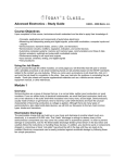
Recommended Battery Size
The recommended battery sizes are given in the table
below. The table is in two parts: the top part recommends
battery sizes when 0.47μF capacitor EOL devices are
used with 2, 4 or 8 zone panels and with 24hr or 72hr
battery backup. The second part recommends battery
sizes when 4k7 resistor EOL devices are used with 2, 4
or 8 zone panels and with 24hr or 72hr battery backup.
The table below gives a quick guide to the battery size
required, provided that no load is connected to the
auxiliary output on the PSU PCB. If you need more detail,
or have connected an auxiliary load, please refer to the
full calculation table in Section 9 Battery Calculation.
Note that the table below may specifiy slightly larger
batteries than using the calculation in Section 9.
EOL
Alarm Current Standby Time
2 Zone
4 Zone
8 Zone
0.47 F
Up to 1A
24hrs
2.8
2.8
2.8
Capacitor
Up to 1A
72hrs
7
7
7
4k7
Up to 1A
24hrs
2.8
7
7
Up to 1A
72hrs
7
7
7*
Resistor
* Maximum of 2 zones with 4k7 EOL
Using Larger Battery Sizes
The largest battery size that can be installed in the back
box is 7Ah. Batteries less than 1.6Ah should not be
used.W
Battery Disposal
As a mimimum, replace batteries every four years.
Always dispose of batteries in accordance with the battery
manufacturer’s recommendations and local regulations.
19
997-492-000-4, Issue 4
March 2006
EN54 & ISO 7240 2-8 Zone Conventional Fire Panel - Installation & Configuration Manual
6.5 Configuration and Handover
CAUTION - Heat Hazard!
Under certain fault conditions
PCB areas identified by this
symbol may reach high
temperatures.
After all external wiring has been connected to the panel
and with no faults existing, the panel can be configured
for the particular system requirements.
After configuration has been completed and after any
faults revealed have been rectified, the system will be
ready for commissioning tests.
The configuration process is only possible with the panel
at access Level 3. Access Level 3 can only be achieved
when the front cover is not fitted (refer to Section 2.5.1
Removing the Cover). With the cover removed, while
holding down the
pushbutton, press the following
pushbuttons in the order given -
,
and
.
Access Level 3 state is confirmed by the rapid flashing of
the FIRE LED.
6.6 Commissioning Tests
The following tests should be carried out after panel
configuration is complete. Refer to the User Manual (997493-00X) sections as listed below:
Test LEDs Test zones Test buzzer Test outputs -
refer to Section 6.1
refer to Section 6.2
refer to Section 6.1
refer to Section 6.2.
6.7 Zone Wiring
EN54-2 : 12.5.2 &
ISO 7240-2: Annex D
Not more than 32 fire
!
EN54 detectors and or MCP’s
ISO 7240 may be connected to
one zone.
All methods support installations where detectors and
MCPs are segregated into different zones with separate
wiring. This is necessary to comply with local standards
in some areas and also if a delay strategy is used.
Methods 1 and 2 support connection of MCPs and detectors
in any order and require the use of Schottky diode bases.
Method 3 requires MCPs to be connected electrically
nearer to the panel ahead of any detectors. Either
standard or Schottky bases may be used.
Method 1: Recommended
This method is recommended for all new systems. The capacitor
EOL allows the panel to provide enhanced fault detection with
lower power consumption than methods described below.
470R
(nominal)
0.47μF
Schottky diode (short-circuited when detector is fitted)
+ -
+ -
Main PCB Zone
Input Terminations
997-492-000-4, Issue 4
March 2006
Note: When using Apollo 65 detectors and one has been
removed, the panel may fail to latch alarms from
* EOL device: use a 0.47μF capacitor or an AEOL.
20
EN54 & ISO 7240 2-8 Zone Conventional Fire Panel - Installation & Configuration Manual
all detectors located between the removed device
and the panel. Although the use of a capacitor EOL
device meets the requirements of the standards,
method 2 should be used when alarm latching of
all detectors is required with one removed.
Method 2:
Supports new and existing installations using Active Endof-Line (AEOL) - PN: 020-417. For the AEOL to function
correctly an additional 10μF stabilising capacitor must
be fitted across the zone terminals (not supplied - order
PN: 020-743).
Method 3
Supports existing installations where there is a 4K7 resistor
EOL fitted already and it is preferable to install the panel
without modifying the existing wiring. Call points must be
wired nearer to the panel than detectors.
Capacitor:
Use 0.47μF.
MCP
MCP
470R
(nominal)
470R
(nominal)
4k7
Schottky diode bases can be used.
+ -
+ -
Main PCB Zone
Input Terminations
Refer to Section 6.4.1 for details on standby battery sizes
and maximum number of zones.
Note: This method is not recommended for new
installations.
21
997-492-000-4, Issue 4
March 2006
EN54 & ISO 7240 2-8 Zone Conventional Fire Panel - Installation & Configuration Manual
6.8 Sounder Circuits
Two sounder output circuits are provided. The termination
block, TB1, for the sounder circuits is located at the top
left-hand corner of the PSU PCB.
DO NOT CONNECT UNTIL ALL ZONES HAVE BEEN
CONFIGURED AND TESTED.
Before the sounder circuits are connected it is
recommended that all detection circuits are checked to
prevent the possibility of spurious alarm conditions being
generated. The sounders should be polarized and
suppressed using IN4002 (or similar) diodes and the
circuits should be fitted with 4k7 end-of-line resistors.
EN54-2 : 7.7.1 &
ISO 7240-2
!
One output on the panel
EN54 must be configured as a
ISO 7240
fire output.
EN54-2 : 8.8 &
ISO 7240-2 : 9.8
!
One output on the panel
EN54 must be configured as a
ISO 7240
fault output.
Each of the two circuits can be configured as a sounder
output, a Fire routing output or a Fault output. Refer to
Section 7 Configuration for details.
To comply with the requirements of EN54:
i
One output on the panel must be configured as a fire
output, e.g. a monitored sounder or fire routing output
(EN 54-2, 7.7.1).
ii One output on the panel must be configured as a
fault output (EN54-2, 8.8). If the optional 2-way Relay
PCB is not fitted, one of the sounder outputs must be
configured as a fault output. Note that as the fault
output is not monitored it is not compliant with the
requirements of EN54-2, 8.9 as a routing output.
Procedure
1 Use a low-voltage, digital multimeter to check the
resistance across each of the sounder circuits:
i
With the meter connected in reverse polarity (+ve to
-ve and -ve to +ve) the reading should be 4k7.
ii With the multimeter connected to the circuit in normal
polarity (+ve to +ve and -ve to -ve) the meter may
indicate a lower value. This is because of the forwardbiased diodes in series with the sounders.
2 If electronic sounders are used this test will not reveal
reversed devices. It is, therefore, recommended that
if the circuit appears correct the following is done:
i
Remove the 4k7 resistors from the panel outputs.
ii Connect the circuit to the panel output while observing
correct polarity.
iii If there are any reversed devices the panel will indicate
a fault. Re-check circuit. Locate reversed sounder
wiring and correct. Panel fault indication will clear.
3 When the output circuits have been connected, they
may be tested by using the SOUNDERS START/
STOP pushbutton.
i
Press the SOUNDERS START/ STOP pushbutton to
activate the sounders.
ii Press the SOUNDERS START/ STOP pushbutton
again to stop the activation of the sounders.
997-492-000-4, Issue 4
March 2006
22
EN54 & ISO 7240 2-8 Zone Conventional Fire Panel - Installation & Configuration Manual
6.9 Digital Inputs
Two digital input circuits are provided. Terminal block,
TB5, is provided on the Main PCB for these input circuits.
Each circuit is configurable, at access Level 3, as a
dedicated input function - refer to Section 7.7 Digital
Inputs for details.
23
997-492-000-4, Issue 4
March 2006
EN54 & ISO 7240 2-8 Zone Conventional Fire Panel - Installation & Configuration Manual
6.10 Fault Finding Chart
Use this chart to identify the cause of possible problems
when commissioning your system.
997-492-000-4, Issue 4
March 2006
24
EN54 & ISO 7240 2-8 Zone Conventional Fire Panel - Installation & Configuration Manual
7
ISO 7240-2 : 14.5.3e), f)
Installers must make a record
of the configuration details of
the panel and store the
ISO 7240
information at access
!
level 3.
A copy of the configuration map (see the
back page) marked up and dated would
make a suitable record. Any change of
configuration will require a new
configuration record.
Configuration
Access Level 3 allows input, output and control functions
to be configured.
The following sections describe how to configure the
panel. Each procedure requires the panel status to be
at access Level 3. The state of the configurable options
is indicated by the panel LEDs.
The table at left shows the functions of each pushbutton
at access Level 1/ 2 and Level 3.
The Configuration menus are as follows:
1
2
3
4
5
Miscellaneous: Panel Options; System
Zones: either 1- 2, 1- 4 or 1- 8
Output circuits: 1- 4*
Digital Inputs: 1 and/ or 2
Delays: first stage; second stage.
* Each output can be configured as a monitored or voltfree relay output. Output circuits 3 and 4 can be provided
using the optional 2-way Relay PCB (kit PN: 020-713).
Manual Zones
The odd-numbered zones are configured as manual,
i.e. MCP-only, zones. Manual zones can be changed so
they can form part of a day-time delay strategy.
7.1 Entering Access Level 3
To enter access Level 3: hold down the
pushbutton
and press the following pushbuttons in the order given ,
and
. Rapid flashing of the FIRE LED
confirms that the panel is at access Level 3. You can
now access the configuration options in any order.
The Level 3 function of each pushbutton is indicated
using an icon within brackets immediately above each
pushbutton.
Press the following pushbuttons to select menu options:
- Panel/ System Options
- Zone Input/ EOL Type
- Output Type/ Delay
- Digital Inputs
- Delays.
Press
to cycle through the sub-menu. Press
at
anytime to return to the Top Level menu.
See the configuration map on the back cover of this
manual for a quick reference guide.
25
997-492-000-4 , Issue 4
March 2006
EN54 & ISO 7240 2-8 Zone Conventional Fire Panel - Installation & Configuration Manual
7.2 Panel Options
Four user-configurable panel options are available:
a. Enable/Disable Engineering Mute
b. Enable/Disable Commissioning Mode
c. ACCEPT pushbutton access level
d. LAMP TEST pushbutton access level.
e. Delay Lights DISABLEMENT LED
7.2.1
Engineering Mute
The operation of the panel’s buzzer can be changed so that
it operates only occasionally with a Fire state, fault condition
or during any active configured first stage delays. This can
be selected independently of Commissioning Mode.
The default is Engineering Mute disabled.
7.2.2
Commissioning Mode
The panel can be put in Commissioning Mode to assist
the commissioning process.
In this mode, most faults are indicated after 4 secs instead
of the normal 20 secs delay to aid fault finding.
Commissioning Mode times-out automatically 60 secs
after the cover is replaced. Selection of commissioning
Mode automatically selects the Engineering Mute function.
7.2.3
ACCEPT Pushbutton Access Level
The ACCEPT pushbutton can be configured to operate
at access Level 1 or 2. The default operation is access
Level 2.
7.2.4
LAMP TEST Access Level
The LAMP TEST pushbutton can be configured to
operate at access Level 1 or 2. The default operation is
access Level 2.
EN54-2 : 9.2a), 9.4.2c)
Delays to outputs is a disablement.
To comply with EN54, select ‘Delay
Lights Disablement LED’.
ISO 7240-2: Annex E
Does not require delay
indicated as a disablement.
7.2.5
Delay Lights DISABLEMENT LED
Indication of a configured delay to outputs (a
disablement) is required by EN54 (default). Use this
option when the DISABLEMENT LED is not required to
indicate any configured delays.
7.3 Fault Options
The following options are selectable:
a. Non-latched faults
b. Mains fault delay.
7.3.1
Non-latched Faults
When enabled, this option allows faults and fault
indications to clear automatically. The buzzer can still be
silenced while a fault is shown on the panel (it will resound
if the fault reoccurs). By default the option is disabled and
fault indications require manual intervention to clear.
Non-latching only affects the following fault conditions:
a. Zone Faults
b. Earth Fault
997-492-000-4, Issue 4
March 2006
26
EN54 & ISO 7240 2-8 Zone Conventional Fire Panel - Installation & Configuration Manual
c. Power Supply Fault
d. Sounder Fault
e. Fire Output Fault
f. Fault Output Fault
g. Auxiliary Supply Fault.
Note: System Fault remains latching at all times.
7.3.2
By default, a mains fault is indicated within 10 seconds.
This option allows the delay to be extended to 30, 60 or
90 minutes. The 60 minute and 90 minute options do
not comply with EN54 (see information at left).
EN54-4: 5.4
A mains fault MUST
be indicated within 30
minutes.
ISO 7240
!
Mains Fault Delay
Note: The Non-latched faults and Mains fault delay
options can be used together. For example, if the
delay is set to 30 minutes then the fault is indicated
after this time. The indication is removed
automatically 10 seconds after the fault is cleared.
ISO 7240-4 : 5.4
A mains fault MUST
be indicated within
100 seconds.
7.4 System Options
The following options are selectable:
a. Clear Checksum
b. Select Default Configuration
7.4.1
Clear Checksum
Use this selection to clear user configuration checksum
faults.
7.4.2
Select Default Configuration
This enables the panel to be returned to the factoryconfigured state. When System LED 2 is lit the panel is
in the factory-configured state.
7.5 Fire Zone Input Type
Fire input zones can be configured as follows:
a.
b.
c.
d.
e.
f.
7.5.1
EN54-2 : 7.6 & ISO 7240-2
!
EN54
ISO 7240
1. Configuring a local
detection zone as nonlatching contravenes the
requirements of EN54 and
ISO 7240.
Latching/non-latching alarms
Alarm or for short-circuit operation
Auto or manual operation mode
Coincident-alarm or separate-alarm detection
Setting a Sprinkler Verification Time.
EOL Device Type.
Latching/Non-latching Alarms
A detection zone can be configured as latching or nonlatching. When selected as latching, if the panel enters
the fire (or fault) state this condition will remain active
until the panel is reset. When selected as non-latching,
the panel state returns to normal once the input condition
has been cleared. The default is latching.
2. Reset from an alarm state must be a
manual operation at access Level 2.
27
997-492-000-4 , Issue 4
March 2006
EN54 & ISO 7240 2-8 Zone Conventional Fire Panel - Installation & Configuration Manual
7.5.2
Alarm or Short-circuit Operation
The panel can be configured to respond to a short-circuit
input on a zone as a fire or fault condition. The default is
fault indication.
Caution: You will contravene the requirements of
EN54-2 if you configure short-circuit as a fire
condition. For guidance, refer to appropriate
local fire standards.
EN54-2 : 8.2.4a) &
ISO 7240-2 : 9.2.4a)
!
The panel must indicate
EN54
a fault condition for a
ISO 7240
short circuit.
7.5.3
Auto/ Manual Zones
The panel has the following factory-configured default:
a. Odd-numbered zones - manual zone, i.e. no delay to
activation of outputs, used with MCPs. Manual zones
will always cause immediate entry into the Fire state.
b. Even-numbered zones - auto. detection, i.e. if
configured for day-time delay strategy, outputs will
be delayed as per the delay strategy.
Note: If no delay strategy is being used (default panel
setting) this operation has no effect.
Any zone can be configured as manual or auto action.
7.5.4
Coincidence Detection
The panel will, by default, indicate a fire condition when
a single device on a single zone goes into alarm.
The panel can be configured so that to enter a full fire
condition, two zones must be in the fire state.
Coincidence detection is only supported for pairs of zones,
i.e. zone 1 concident with 2, zone 3 coincident with 4,
etc. When configured, upon the first zone going into fire
the respective zonal fire indicator illuminates, the panel
enters the alert state but the general fire LED does not
light.
Note: Zone pairs set for coincidence detection are forced
to function as auto zones.
On the second fire alarm zone the standard fire sequence
will be followed for both input zones.
7.5.5
EN54-2 : 7.1.3 &
ISO 7240-2
!
The panel must respond
EN54
to an input within 10
ISO 7240
secs.
Sprinkler Verification Time
A 2 sec. verification time is applied to all inputs to reduce
the occurrence of false indications of alarm due to transient
phenomena. When monitoring an input from a sprinkler
system it may be necessary to configure a sprinkler
verification delay. This is an exceptional situation and will
require the approval of a fire officer.
7.5.6
EOL Device Type
Use this option to change the default EOL device type
from a capacitor to a resistor when the panel is used for
retrofit installations.
Note: Failure to do this on retrofit installations may cause
the panel to enter the Fire state, with consequent
operation of the sounders.
997-492-000-4, Issue 4
March 2006
28
EN54 & ISO 7240 2-8 Zone Conventional Fire Panel - Installation & Configuration Manual
7.6 Sounder Output Type/ Delay
The two sounder circuits and two optional relay circuits,
if fitted, are each configurable as one of the following:
a. Sounder output
b. Fire routing output
c. Fault output.
d. Local Alarm Output.
EN54-2 : 7.8 & ISO 7240-2
Only a monitored sounder
!
output may be used as a
EN54
compliant fire routing
ISO 7240
output.
Up to two optional, 8-way Relay PCB(s) can be fitted.
Each PCB can be independently configured to provide
one of the following functions:
e. Repeat Zonal Output
f. Coincident Zonal Output
g. Repeat Zonal Output (zones 1-4) and Shop Interface
Outputs
h. Inputs and Shop Interface Outputs.
EN54-2 : 8.8 & ISO 7240 : 9.8
Either a relay1 or a sounder
!
output1 may be configured
EN54
as a fault output.
ISO 7240
1
These outputs are not monitored and
they should not be used as a fault routing
output (EN54-2: 8.9 and ISO 7240 : 9.9).
7.6.1
Select Output
Select Sounder 1, Sounder 2, or if the 2-way Relay PCB
is fitted, Relay 1 or Relay 2. The default selection is
Sounder 1. Press
7.6.2
to select another output.
Select Type
Having selected the appropriate output circuit now select
one of the following: Sounder, Fire Routing Output, Fault
output, Local Alarm Output or Pulsing Sounder Output.
The default type for Sounder circuits 1 and 2 is Sounder.
Sounder output types
‘sounder’ and ‘pulsed’ must
not be mixed on the same
installation to avoid
confusion of the
evacuation signal.
Press
to select an alternative type.
Notes:
1 The Local Alarm Output does not activate with nonlatched zones (assumes non-latched zones are from
external panels).
2 The pulsing option will activate the selected sounder/
relay outputs as follows: one second ON / one second
OFF.
7.6.3
Select Delay
These outputs can be configured as part of a strategy to
delay the operation of sounder and/ or fire routing outputs
during daytime operation.
Each sounder/ fire routing/ fault routing/ local alarm output
can be configured with a two-stage delay (see Section 7.8
Primary and Secondary Delays). Once configured the
DELAY ON/OFF pushbutton must be pressed, or Digital
Input, to enable the delay to outputs. This panel state is
confirmed by the illumination of the DELAY ON LED and
DISABLEMENT LED (panel default).
29
997-492-000-4, Issue 4
March 2006
EN54 & ISO 7240 2-8 Zone Conventional Fire Panel - Installation & Configuration Manual
7.7 Digital Inputs
Two digital input circuits are provided for connection to
ancillary equipment, if required. Each circuit can be
configured to provide one of the following input actions:
a. Class change (default)
b. Alert
c. Evacuate
d. Delay Mode (default)
e. Reset
f. Fire transmission confirmed return signal
g. Fault transmission failed return signal.
EN54-2 : 7.6.1, 7.8 &
ISO 7240-2
!
Level 2 Keyswitch
EN54
access MUST be used
ISO 7240
with these inputs.
Class Change: When a class change digital input is
activated, all outputs configured as sounders will be
activated until the input condition is removed.
Alert: When an alert digital input is activated, all outputs
configured as sounders and the internal buzzer start pulsing.
The sounders and internal buzzer remain pulsing until the
digital input is deactivated. Alert operation will override class
change and fault conditions, but not the alarm condition.
Note: If the sounder output is configured as type ‘pulsed’
then an alert input will cause the sounder outputs
and internal buzzer to turn on with a steady tone.
Evacuate: When an evacuate digital input is activated, a
general evacuate is initiated, i.e. all the bells activate,
until the input condition is removed.
Note: If the sounder output is configured as type ‘pulsed’
then an evacuate input will cause the sounder
outputs and internal buzzer to pulse.
Delay Mode: This allows external control of delays to
outputs. It can be used to delay activation of outputs
during the day and so this use is commonly known as
Day Mode. When this input is active, delays can still be
cancelled using the ‘Delays On/Off’ button.
Reset: This digital input can be used to return the panel
to normal operation after the occurrence of an event,
such as an alarm or fault. Faults are latching and a reset
cannot return the panel to normal until the condition
causing the fault has been remedied.
Fire Transmission confirmed return signal: This type of
digital input provides the ability to confirm the activation
of the Fire Routing Output.
Fault Transmission failed return signal: This type of digital
input provides the ability to route Fault Routing Output
faults back to the panel. It is assumed that the external
equipment will provide the necessary fault monitoring of
the routing output and provide feedback to the panel.
7.7.1
Select Input
Select Digital Input circuit 1 or 2. The default selection is
input 1. Press
997-492-000-4, Issue 4
March 2006
30
push-button to select the other output.
EN54 & ISO 7240 2-8 Zone Conventional Fire Panel - Installation & Configuration Manual
7.7.2
Set Type
Digital input 1 is configured, by default, as a Delay Mode
input. Digital input 2 is configured, by default, as a Class
Change input. Press
push-button to select another type.
7.8 Primary and Secondary Delays
A day-time delay strategy can be implemented, if
required, which comprises two user-configurable delay
periods to allow a fire search to take place. These delay
periods are referred to as primary and secondary. On
an auto detection zone, every fire state places the panel
in a full alarm, hold-off state until the indicated fire event
has either:
a. Been verified as true after the search and then
manually-terminated (at the panel or by operating an
MCP), or
b. The primary delay period expires, thereby
automatically operating the configured outputs (e.g.
sounders).
If the ACCEPT pushbutton is pressed during the primary
delay period the delay to outputs is extended by the length
of the configured secondary delay. The maximum total
duration of a configured delay to outputs is 10 minutes,
even if the sum of the configured primary and secondary
delays exceeds this limit. Once the ten-minute delay
period has expired the outputs will be activated
automatically.
7.8.1
Select Primary Delay Time
Specify the first stage of the delay to outputs. The default
is 30 secs. Press the
push-button to specify another
primary delay period up to 120 secs in 30 sec increments.
7.8.2
Select Secondary Delay Time
Specify the second stage of the delay to outputs. The
default is 1 minute. Press the
push-button to
specify another secondary delay period up to 10 minutes
in 1 min increments.
7.8.3
Two-zone Override Delay
Delays to outputs are overridden when a second zone
goes into fire. This default can be changed so that a
second zone going into fire does not override an active
delay.
31
997-492-000-4 , Issue 4
March 2006
EN54 & ISO 7240 2-8 Zone Conventional Fire Panel - Installation & Configuration Manual
7.9 Configuration Examples
The following examples are provided to offer guidance
when navigating through some of the menu options.
Note: If you lose your way at any time, simply press the ‘main
menu’ pushbutton
to return to the menu select
position.
Example 1
How do I configure the panel back to the factory default
state?
Ensuring that the panel is at access Level 3 (refer to
earlier in this section). Use the icons in brackets (located
above each pushbutton) when proceeding:
Press the following pushbuttons in the order shown:
- Selects Miscellaneous option
- Selects Configuration sub-item menu
(hold for 5 seconds) - System LED 2 lights to
indicate the factory default condition has been restored.
Press the
pushbutton to return to the top level and
select another configuration menu option. To take the
panel out of access level 3, press the
pushbutton.
Note: The panel remains at access Level 2 until the cover
is relaced when access level is dependent on key
position.
Example 2
How do I set a delay of 1 min for sounder output circuit 2?
With the panel at access level 3, press the following
pushbuttons in the order shown:
Selects Sounder Outputs option
Use to select sounder circuit 2
Use to select delay to output - LED 10 illuminates
to confirm selection of sounder circuit delay.
To enable the configured output delay for sounder circuit
2, and with the panel at access Level 2, the
pushbutton must be pressed and the DELAY ON and
DISABLEMENT LEDs illuminate to confirm the panel has
a delay to outputs configured.
Press the
pushbutton to return to the top level and
select another configuration menu option. To take the
panel out of access level 3, press the
997-492-000-4, Issue 4
March 2006
32
pushbutton.
EN54 & ISO 7240 2-8 Zone Conventional Fire Panel - Installation & Configuration Manual
8
Specification
General
The Fire Control Panel is designed to comply with the
requirements of EN54 Part 2/4 and ISO 7240 Part 2/4. In
addition to the basic requirements of EN54-2 and ISO 7240,
the panel may be configured to conform with the following
optional functions - the applicable clauses of these standards
are referenced as follows:
Options
Clause
Controls:
Delay of the immediate actioning of outputs
7.11
Coincidence Detection
7.12
Test condition
10
Outputs:
Fire alarm device(s) (Sounders)
7.8
Fire alarm routing equipment
7.9
This panel complies with the European Low Voltage Directive
73/23/EEC (and the amending Directive 93/68/EEC), by the
application of the safety standard EN60950.
The panel conforms with the essential protection
requirements of the EMC Directive 89/336/EEC (and the
amending Directives 92/31/EEC and 93/68/EEC), by the
application of EN61000-6-3, (emissions) and EN50130-4,
(immunity).
Mechanical:
Construction:
Fire-resistant, ABS plastic moulded front
cover and back box. Cover contains all
user interface controls and visual
indicators.
Dimensions (mm): 318(h) x 356(w) x 96(d)
Approx. Weight:
2kg (no batteries)
Environmental:
Climatic classification: 3K5, (IEC 721-2-3)
Operating temperature: -5oC to +45oC, (recommended +5oC
to 35oC)
Humidity:
5% to 95% R.H.
Height above sea level:Maximum, 2000m
Panel sealing:
IP 30, (EN 60529)
Vibration:
EN 60068-2-6, 10-150Hz at 0.981ms-2,
0.1g n (Meets the requirements of
EN 54-2/4)
EMC:
Emissions:
EN 61000-6-3
Immunity:
EN 50130-4
Safety:
33
EN 60950
997-492-000-4, Issue 4
March 2006
EN54 & ISO 7240 2-8 Zone Conventional Fire Panel - Installation & Configuration Manual
Indicators and Controls:
LED Status indicators: Alarm, Zonal Fire, Zonal Fault, Power,
General Fault, General Disablement, Test,
Delay On (active), System Fault, Earth
Fault, Power Supply Fault, Sounder Fault/
Disabled, Fire Routing Active, Fire
Routing OutputFault/Disabled, Fault
Output Fault/Disabled, Auxiliary Fault.
Controls:
Two-position keyswitch:
Level 1 (key removed or in ‘remove’ position)
Level 2 access (key turned 90° clockwise).
Dedicated push-buttons are provided for the following functions:
ACCEPT, SOUNDERS STOP/START,
RESET, BUZZER MUTE, DELAY ON/
OFF, ITEM SELECT, DISABLE/TEST/
NORMAL, LAMP TEST.
External Connections:
Cable entry:
18 x 20mm knock-outs on top face of
back box. One 25mm x 50mm knockout on rear wall of back box.
Electrical:
Classification:
Conductor size:
A combination of Installation Class 1
and Class 2 (panel must be earthed).
Compatible with cable conductor
sizes: 0.5mm2 to 2.5mm2 .
Supply Rating:
Mains supply to the panel is to be provided via an external,
double-pole, mains-isolation unit. The supply rating is:
230V~ (ac) ±15%, 50/ 60Hz, 1.6A.
Power Supply Specification:
Input Fuse rating:
T 1.6A H 250V
Output ratings:
Output voltage:
Output current:
Ripple voltage:
18.5 - 28.5Vdc
1.8A (includes charger current - charger
disabled during alarm)
200mV (peak-to-peak)
Output Ratings - Charger:
Charger voltage: 27.3V at 20°C (temperaturecompensated at -3mV/°C/cell)
Charger current: 0.4A
Range of battery size charged to 80% in 24hrs:
1.6Ah - 7Ah
Recommended Standby Battery Sizes:
24 hour standby period - 2.8, 3.3 or 7Ah
72 hour standby period - 2.8, 3.3 or 7Ah.
997-492-000-4, Issue 4
March 2006
34
EN54 & ISO 7240 2-8 Zone Conventional Fire Panel - Installation & Configuration Manual
Note 1: Internal batteries - sealed lead-acid types are
recommended. The following manufacturers/ type are
recommended: Yuasa-NP, Fiamm FG and Jackyl.
Note 2: The batteries should be replaced at intervals not
exceeding four years. Their lifetime is dependent upon
the ambient temperature; refer to manufacturer’s
technical specification for guidance.
Outputs:
Sounder Circuits:
Two outputs configurable as sounder, fire routing output or
fault output and each rated at 0.5A. The sounder and fire
routing outputs are monitored.
20.0 - 28.5Vdc, (24Vdc nominal) rated at 0.5A.
Note: If the total alarm current (sounders + fire + Auxiliary output)
exceeds a total load of 1A, you must check the total
alarm load using the Battery Calculation in Section 9.
Zone Circuits:
Factory-supplied two, four or eight detector zones.
The quantity of detectors per zone equals 2.0mA divided by
the individual detector’s quiescent current rating - see
manufacturer’s data sheets - e.g. for a detector quiescent
rating of 75μA; the quantity of detectors:
= 2.0mA ÷ 75μA = 26 detectors.
Auxiliary Output:
18.5V - 28.5Vdc (24Vdc nominal) rated at 0.5A
Optional 2-Way Relay PCB providing:
A Fire Relay Output
A Fault Relay Output
Each relay is rated at 30Vdc, 1A.
Note: To comply with the requirements of EN54-2: 8.8, if
the 2-way Relay PCB is not fitted one of the sounder
circuits must be configured as a fault output.
Optional 8-Way Relay PCB providing up to 8 outputs per
PCB (two PCBs may be fitted). Relay contact functions are
configurable using jumper links to provide the following:
Repeat Zonal Output or
Coincident Zonal Output or
Repeat Zonal Output (zones 1-4) and Shop Interface
Outputs or
Inputs and Shop Interface Outputs
Max current (per PCB):
Quiescent - 0.1mA
Alarm/ all active - 80.1mA
Each relay is rated at 30Vdc, 1A
Fire resistor:
Nominal 470R ±5%
Digital Inputs:
0- 32Vdc or contact closure.
Low = 0 - 1.35V
High = 3.15 - 32V.
35
997-492-000-4, Issue 4
March 2006
EN54 & ISO 7240 2-8 Zone Conventional Fire Panel - Installation & Configuration Manual
9
Battery Calculation
The table in Section 6.4.1 Standby Batteries can be used
to select the correct battery size. If full calculations are
required use the procedure below.
General Data
PSU size
Maximum
No. of sounder
Circuits
1.8A
Maximum
Internal
External
Battery Size
Alarm Load
Range
2
1A
1.6 - 7Ah
Standby Load (Amps)
Standby Load in Amps
Basic panel
No.
Current
1
0.034
Total
0.034
Device quiescent current
(max 2mA per zone)
EOL Current (per zone) fitted with Resistor EOL
0.0056
Auxiliary equipment *
Total Standby Load (L1)
Peak/ Alarm Load (Amps)
Standby Load in Amps
Basic panel
Zones alarm current
Optional 2-way Relay PCB
*
Ensure that any current taken from
the Auxiliary output through the relay
circuits are included in the ‘Auxiliary
equipment’ boxes for alarm and
quiescent.
Qty
Current
Total
1
0.034
0.034
2/ 4/ 8
0.03
0/ 1
0.04
Optional 8-way Relay PCB(s) 0/ 1/ 2
0.08
Sounder output 1
Sounder output 2
Auxiliary equipment *
Total Alarm Current (L2)
Total <1.8A
Calculation
Cmin
=
1.25 {(L1 x T1) + (2 x L2 x T2)}
=
1.25 x .................................. A
=
........................................... Ah
Next available battery ........................... Ah
T1 = Standby time in hours, e.g. 24, 72, etc.
T2 = Alarm time in hours.
This formula calculates the battery capacity required to
provide the specified standby period plus half-hour alarm
load in accordance with BS5839 Part 1 and LPS1014.
997-492-000-4, Issue 4
March 2006
36
3
2
1
Zones
Outputs
Odd-numbered zones are manual; evennumbered zones are auto.
No outputs are delayed.
Only monitored sounder outputs are
suitable for use as fire routing outputs.
1
2
3
3
2
1
8
7
6
5
4
3
2
1
Miscellaneous
Default states are shaded. The following default
issues should be noted:
1
5
1
Select zone
5
4
3
2
1
12
11
10
9
8
7
6
5
4
3
2
1
Mains fault delay
Non-latched faults
Select Default
Configuration
(5 sec hold down)
Clear Checksum:
Verification
Delay:
Coincidence:
Auto/ Manual:
Non-latching
alarm:
Short circuit
alarm:
EOL Device Type
12
Select Sounder
output delay:
9
3
8
10
4
3
2
1
5
5
6
7
8
5
6
7
8
2
3
4
2
3
4
10
9
8
7
6
1
Delay
10
9
8
7
6
8
7
Capacitor
1
Resistor
8
7
6
90s
30s 60s
6
5
Separate
Coincident
2s
Auto
6
Manual
9
11
6
6
5
4
Fault
8
6
5
5
3
Alarm
10
Select output type:
4
4
OK
3
3
Default Config.
Config. changed
Fault
6
5
4
3
Latching
7
2
1
Select output circuit:
Sounder 1
Sounder 2
Relay 1 (Fire O/P)
Relay 2 (Fault O/P)
Output Type/ Delay
1
Disabled
10s 30m 60m 90m
Enabled
Yes
Level 2
Level 1
No
Level 2
Level 1
Non-latching
Input Zone EOL Device
5
4
3
2
1
Input Zone Type
2
1
System
2
1
Fault Options
5
4
3
Enabled Disabled
Enabled Disabled
7
6
5
4
3
2
1
6
5
4
3
2
1
8
7
6
5
4
3
2
1
8
7
6
5
4
3
2
10
9
8
7
6
No Delay
10
9
8
7
6
4
3
2
1
R
Y
LED ON (intermittent)
LED ON (continuous)
Miscellaneous
Menu
Delays
Digital Inputs
Outputs
Zones
Flashing Rapidly
Second Stage
First Stage
Input Type
Output Type
Flashing
Flashing
12 Flashing
5 Flashing
11
3
11
5
2 Flashing
9 Flashing
Input Type
EOL Type
3 Flashing
Flashing
Delays
System
7
2
Panel Options
Fault Options
LED
6 Flashing
Sub-menu
Which Menu Are You In?
Common Fire LED
Are You in Access Level 3?
Key:
5
4
Digital Inputs
4
5
6
7
8
9
10
4
5
6
7
8
9
10
First Stage Delay
Not
selected
Selected
8
7
6
5
4
3
2
1
0
0s
1
2
Two Zones Override
Delay
9
2
1
Second
Stage
Delay:
10
12
10
9
8
7
6
5
4
1
2
3
4
2
3
4
30s
1
10
9
8
7
6
5
4
3
Overrides
LED 2
8
90s
4
3
2
1
9
4
3
2
1
10
120s
10
9
8
7
6
5
4
No Override
7
4
3
2
1
10
9
8
7
6
5
4
Fire Transmission
Confirmed
60s
Minutes
6
4 5
Secondary Stage Delay Time
1
10
11
10
9
8
7
6
5
4
Select Input type:
Select Digital
Input 2:
LED 1
Primary Stage Delay Time
2
1
9
8
7
6
5
4
3
2
1
12
11
10
9
8
7
6
5
4
3
2
1
12
11
10
9
8
7
6
5
4
3
2
1
Select Digital
Input 1:
Digital Input Type
Class Change
(default I/P 2)
Engineering Mute
toggle:
Comm. Mode
toggle:
Accept Operation
level:
Lamp Test
Operation level:
Delay Lights
Disablement LED
Sounder
Evacuate
1
Fault
Alert
2
Fire (3)
Routing
Reset
1
Pulsing
Sounder
Delay Mode
(default I/P 1)
Panel Options
Local
Alarm
Fault Transmission
Failed