1
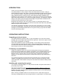
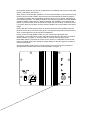
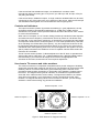
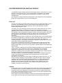
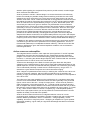
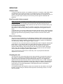
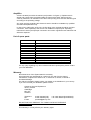
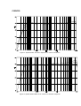
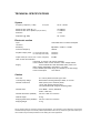
System 600a
USER MANUAL
Contents
INTRODUCTION
1
OPERATING INSTRUCTIONS
1
Unpacking and visual checks
Preliminary recommendation
Installing and connecting the system
Controls and indicators
Use close to TV screens and video monitors
SYSTEM DESCRIPTION AND PHILOSOPHY
Drive unit.
Cabinet
Active crossover and amplifier
1
1
2
3
3
4
4
4
5
SERVICING
Cabinet finish
Dual Concentric driver removal
Drive unit servicing
Checking the unit
Amplifier
List of spare parts
Warranty
6
6
6
6
6
7
7
CURVES
8
TECHNICAL SPECIFICATIONS
9
System
Electronic section
Cabinet
9
9
9
Declaration of Conformity
10
INTRODUCTION
Thank you for purchasing the Tannoy System 600A Active Monitor.
The System 600A is a very compact, active near-field reference monitor. Using an
advanced Dual Concentric 6.5” driver, it offers the advantages of point source operation
in a cost-effective design, combined with the benefits of active speaker technology: a
highly optimised active crossover section; ideal matching between amplifiers and
transducers; higher output for lower distortion. Active user controls are also provided to
allow further bass extension (LF contour) and greater flexibility. The attractive octagonal
shape of the cabinet, with its original rounded edge front panel also contributes to the
excellent acoustic performance of the system.
Designed to be located on top of the mixing console, in a landscape format, it will
equally suit other situations where it can be used in portrait mode without any drawback,
thanks to its point source operation.
This manual is intended to provide the user with some useful advice on how to install
and use the loudspeakers, as well as more technical information about how the system
is designed, and its detailed specifications. Our goal is to help you get the best results
from this monitoring system.
OPERATING INSTRUCTIONS
Unpacking and visual checks
The System 600A are packed in pairs. To get the speakers out of the carton without
damage open the end flaps fully and bend them right back . Remove the upper cushion,
then lift each loudspeaker out carefully.
Inspect the speakers for signs of transit damage. In the unlikely event of this having
occurred inform the carrier and the supplier. Keep all the packaging if damage has
occurred as this will show evidence of any excessive handling forces. It is also a good
idea to keep the carton for future transportation.
Preliminary recommendation
Initially we would like to give you a word of warning about the high sound pressure
levels which these speakers are capable of generating. Over a sustained period of time
levels over 95 dB for 8 hours per day will eventually cause permanent hearing loss.
Because Tannoy monitors have very low levels of time, amplitude and frequency
distortion it is not always obvious that the sound pressure level is high whilst working
with them.
For continuous exposure we recommend the occasional use of a sound level meter
capable of integrating the sound level over a period of exposure according to noise
control standards. This should be used just to check that noise levels are always within
safe limits.
Installing and connecting the system.
The compact, integrated design of a self-powered unit like the System 600A makes it
particularly easy to install.
After having unpacked the unit, first check that the operating voltage is properly set
(rear panel, location 1 in figure 1), and if it is not adjust the selector to the appropriate
position. Also check and if necessary replace the fuse (location 3), as its rating should
match the operating voltage.
When choosing a suitable location for the monitors, bear in mind that the physical
mounting of loudspeakers can have a large influence on performance. For best results
the monitors should be mounted on a rigid structure, preferably with the use of soft pads
(rubber, Sorbothane, Blu-Tak etc..).
When used in the landscape orientation, we recommend location of the monitors so that
the drive units are toed inwards, with their axes oriented towards the listening position.
The distance between the two speakers should be about 1.5 to 2 metres, depending on
the monitoring position. The distance between the monitoring position and each speaker
should be slightly greater than the distance between the speakers. If the speakers are
placed too close to each other the full stereo image may not develop, on the other hand
if you place them too far apart you will notice an audible hole in the middle of the stereo
image.
Ensure that the console position does not obscure the direct sound radiation from the
Dual Concentric drive unit when sitting down. The engineer and producer should have a
clear, uninterrupted view of the monitor loudspeakers.
Having chosen an appropriate location for your monitors and arranged them
accordingly, connect the power cord to the mains socket and turn the power on (mains
switch, location 2 in figure 1). The blue LED on the front panel should now be
illuminated. Before connecting the source to the monitor, it is advisable to ensure that
there is no signal present (by setting the output faders) so that the signal is not likely to
overload the system.
Connect the audio signal source (console output) to the input connector (combined
XLR/jack socket) at the back of the monitor (location 4 in figure 1).
If the source itself has a balanced output, use shielded twin conductor cable
(microphone cable) connecting pin 2/T to pin 2/T, pin 3/R to pin 3/R, and pin 1/S to pin
1/S (using the shield).
If the source has an unbalanced output, a single conductor shielded cable can be used,
connecting pin 2/T of the input to the “hot” signal pin of the source, while pin 3/R and pin
1/S should be linked together and connected to the source signal ground.
Controls and indicators.
The input level switch (location 5) provides a sensitivity (i.e. gain) adjustment, the top
and bottom positions corresponding respectively to -10 dBu and +4 dBu nominal
sensitivities. The position of the input level switches should be identical on each monitor
for correct channel balance.
When set to ‘Free space’, the LF Contour facility (location 6) extends the bass response
and enhances the low frequency content below 150 Hz by means of a Hi-Q 2nd order
Hi-Pass filter. In the ‘Half space’ position the LF signals are unprocessed and the bottom
end response remains that of a vented system i.e. a 4th order (24 dB/octave). Note that
when activating the Hi-Pass filter (‘Free Space’), very low frequencies under 30 Hz will
be significantly attenuated so that mechanical stress on the LF drive unit (excursion) is
maintained within safe operating limits. Also, the boost applied to the signal in the ‘Free
space’ position will reduce the headroom on the LF amplifier channel and therefore the
maximum SPL available.
The HF Contour switch (location 7) allows adjustment of the HF level. Its operates as a
shelving filter above 2 kHz with -2 or +2 dB amplitude and a 0 dB (flat) middle position.
Use this facility if you feel that a flat response is not the most appropriate to the
acoustical environment, and that the HF level requires adjustment.
Use close to TV screens and video monitors.
The cabinet construction incorporates metal plates which provide a degree of shielding
against the magnetic field created by the drive unit. The speakers can be therefore used
relatively close to TV screens without any picture distorting effect. However some
precautions must be taken, depending on which side of the speaker is located close to
the screen. The diagram below gives an indication of the distance required between
each side of the cabinet and the screen nearby. The figures are based on an emitted
stray field not exceeding 0.3 mT (300 Gauss), usually considered as a safe value.
However, as magnetic sensitivity varies from one screen to another, you are strongly
advised to check before making any permanent installation.
Distance required ≥ 8 cm
Distance required ≥ = 0
Distance required ≥ 15 cm
Distance required ≥ 8 cm
Figure 2. Safe distance for magnetic immunity
SYSTEM DESCRIPTION AND PHILOSOPHY
A loudspeaker design naturally splits into various parts: cabinet, lower frequency, higher
frequency, and crossover which, for the System 600A, is integrated in the amplifier
assembly. The design of these parts cannot take place in isolation, as they are all
interdependent.
The integration of all the features described below is what makes the whole loudspeaker
system even greater than the sum of its individual parts.
Drive unit.
The drive unit used in the System 600A monitors is part of the latest generation of Dual
Concentric units designed by Tannoy. Amongst many other features, this range of
drivers incorporates a dual magnet assembly, ‘tulip’ HF waveguide and injection
moulded polypropylene LF cone.
The design of the HF waveguide has been arrived at by making extensive use of CAD
(computer aided design). It matches the acoustic source impedance at the HF
diaphragm into the acoustic environment, shaping the wavefront as it travels down from
the diaphragm ensuring equal path lengths to achieve a spherical wavefront. Wavefront
shaping begins at the diaphragm surface and, because the compression ratio can be
kept relatively low with this design, the distortions due to air non-linearities are
minimised.
The HF diaphragm is made from aluminium and magnesium alloy, with optimised shape
and thickness, suspended by a precision moulded, inert nitrile rubber surround. Its very
narrow roll eliminates resonances below 25 kHz and provides a very stable and
consistent mounting. The roll form ensures high excursions can take place if necessary
yet provides a fatigue-indestructible assembly.
The HF voice coil assembly incorporates a high temperature copper wire chemically
bonded onto a kapton former fitting onto the outside of the HF diaphragm skirt. The
thermal power handling of the voice coil is greatly increased thanks to its ferrofluid filled
magnetic gap.
The LF unit uses a CNC precision injection moulded polypropylene cone, terminated by
a nitrile rubber, high-compliance surround. The characteristic cone termination
impedance is matched by the surround material independently of the required
suspension compliance. The unit system compliance is provided by the rear suspension
where the best degree of mechanical control can be provided.
The shape of the LF cone has been calculated to match the HF hyperbolic waveguide
ensuring the wavefront remains spherical and perpendicular to the cone surface
throughout the propagation.
The heart of the LF unit is the motor system comprising the magnet and voice coil. The
choice of magnet operating point parameters, air gap flux strength, voice coil details
(number of turns, resistance, winding length, diameter etc.), moving mass, dynamic
compliance and drive unit radiating area presents a very complex mathematical
problem where the solutions can take many different forms. Reaching the correct
answers is much easier if computers can be called on to assist with solving the
equations, as Tannoy do for its drivers.
Cabinet.
As well as the drive units, cabinet design plays a major role in the acoustic performance
of a speaker system. Among the problems which can contribute to the degradation of
the emitted sound field, diffractions and reflections caused by the cabinet boundaries
are too often overlooked although they are the cause of most of the irregularities heard
and measured in the higher frequency areas.
In that respect conventional rectangular, sharp corner boxes perform especially poorly.
On the other hand, the shape of the System 600A has been designed with careful
attention paid regarding the sculptured front panel to provide smooth, rounded edges
which minimise side diffractions.
Another problem involved in cabinet design is to ensure that the box will effectively
behave as neutrally as possible, ideally without interfering at all with the sound field
emitted by the drive unit and the port. There are two main ways the box can get into
vibration. First there can be a mechanical transfer of energy between the drive unit and
the cabinet front panel. Preventing this requires the use of a rigid and stiff front baffle,
which is achieved on the System 600A by using a very thick, dense MDF panel. The
second way the cabinet can get into vibration is by transmission from acoustical to
mechanical energy. Since high acoustic pressures are present inside the cabinet this is
quite likely to occur if no attention is paid in order to minimise it. Here the use of rigid
panels is also helpful but, since their stiffness cannot be infinite and therefore their
resonances only shifted towards higher frequencies, enough damping has to be
provided in the cabinet assembly, including panels and joints. Due to its octagonal
shape and its cabinet construction, the System 600A performs very well in that respect.
Its shape tends to decrease the largest dimensions of each side panel, which reduce low
frequency resonances, while the doubled number of side provides additional damping.
In addition to the cabinet construction the volume and port tuning have been carefully
calculated to give the best set of parameters for monitoring applications. There is a
fundamental relationship in loudspeakers between efficiency, cabinet volume and low
frequency performance given that minimal amplitude variations can be tolerated in
monitoring situations.
Active crossover and amplifier.
The integrated active crossover, which splits the input signal into LF and HF separate
amplification channels, has been designed using a dedicated computer simulation
program. The result is an unconventional topology giving optimum electronic transfer
functions, i.e. achieving the desired target response when combined with the acoustical
responses of the LF and HF units in the actual cabinet.
Thanks to the advantages of the Dual Concentric principle, filters with low phase
variations in the overlap frequency range can be used without detrimental effect on the
spatial dispersion, as with conventional multi-way speakers. As a result the group delay
can be maintained practically constant over the whole frequency range, which is
essential to a good transient response and a accurate stereo imaging.
Such a degree of optimisation and accuracy in matching the crossover to the drive unit
cannot be achieved passively, without inducing significant loss of sensitivity and
resulting in highly inconsistent performance because of the variations in the impedance
of the drive units.
The influence of the power amplifiers on the performance of a complete system does
not have to be demonstrated. However this does not reflect generally in any technical
figures, which most of the time - except for output power - seems close to perfection
(ultra low distortion, ultra linear response, etc...). Nobody would trust figures showing
that an amplifier with 0.002% distortion will sound worse than another with only 0.001%.
Not entering a technical discussion about why an amplifier can sound “warm”, or “harsh”,
or “dry”, this is another reason to choose a complete (e.g. a self-amplified speaker)
rather than a split system where you cannot predict the overall result until the chosen
amplifier is actually connected to the speaker.
Another obvious reason that favours an integrated solution is that, as in most
engineering work, designing an amplifier is a matter of making the right compromises
between different parameters, often in contradiction : voltage capability, current
capability, short term or long term power... Designing an amplifier for a given speaker
(electrically speaking, a given load) is a significant advantage that allows much better
optimisation.
SERVICING
Cabinet finish.
To remove marks and scuffs, use a medium soft brush. If necessary, a little warm water
and detergent can be used, but under no circumstances use a solvent or abrasive
cleaner. The surface will change colour when wet but will return to normal when dry. For
touch-up of paint chips contact your local Tannoy service agent for materials and
guidance.
Dual Concentric driver removal.
Before any servicing operation the amplifier should be disconnected from signal input
and mains power.
Lay the cabinet on its back taking care to protect the rear plate. Remove the four
hexagonal bolts and set aside. Ease the driver from the front of the cabinet taking care
not to mark the front surface.
Use a piece of stout cardboard to lever against if necessary. Remove the driver and
disconnect the internal wiring, taking care not to damage the moving parts of the LF
driver.
To refit the driver, connect the cables from the wiring harness to the LF (brown and blue
leads) and HF (yellow and green) terminals. Fit the driver into mounting hole, fasten the
bolts finger tight and then progressively torque them down so that the driver seats
evenly.
Drive unit servicing.
The HF unit may be fitted with a new diaphragm assembly. With the driver face down,
release the three bolts securing the HF assembly and lift the HF unit vertically upwards
and away from magnetic attraction caused by the LF magnet. Replace the diaphragm it is self-centring - taking care to align the parts correctly.
To refit the HF unit, hold it about 300 mm vertically above the LF magnet in both hands
while resting on your elbows. Slide your elbows apart and lower the HF unit onto the
back of the LF magnet. As the HF unit gets close to the magnet you will feel the
magnetic fields repelling. Align the fixing holes and secure with the bolts, tightening
down evenly. Do not tighten the bolts finally until you are sure the HF unit is seated
correctly and the two magnet systems appear parallel.
The LF unit may be re-coned in the normal way. Use only the parts and adhesive
supplied in the re-cone kit.
Checking the unit.
The whole unit can be checked using a sine wave generator connected to the input. A
high quality, low distortion (preferably a beat frequency) oscillator will be required to
check for any buzz and rattle noise generated by the drive unit. The voltage to be
applied at the input should be 0.2 Vrms for input level switch set to +4 dBu. Testing the
whole unit has an obvious drawback in that, in the case of any defect it may be difficult
to determine whether the drive unit or the amplifier is faulty. In which case each part
would have to be checked independently, meaning that the drive unit should be
removed (refer to above).
If for whatever reason the amplifier needs to be removed from the cabinet, care should
be taken to remove only the relevant screws (there are 8 mounting screws, 2 on each
side of the plate).
Amplifier.
A fuse is located just under the mains input (location 3 in figure 1). Replacement is
simple and a spare fuse is provided inside the fuse housing itself. Always use the
correctly rated fuse, as indicated on the silk screen printing, there are two different types
according to the operating voltage.
Any other servicing regarding the electronic section should be undertaken by qualified
and authorised personnel only.
In case of any malfunction of the unit, the first thing to be checked should be the input
connection, more especially if the source has unbalanced outputs (see “Operating
Instructions” section) as improper connection can result in significant level reduction and
affect the response.
List of spare parts.
PART NUMBER
DESCRIPTION
9900 0361
System 600A Cabinet assembly
7900 0411
Driver kit - 1678
7900 0412
Recone kit for LF unit
7900 0406
HF diaphragm assembly
4504 5725
Screw M5 x 30mm hex countersunk black
6184 0042
Port tube
6481 0280
System 600A User manual
6730 0333
Carton kit System 600A
6460 0066
Moulded badge & label
7300 0565
System 600A amplifier- complete unit
7900 0476
System 600A amplifier- cross-over/amplifier PCB (fitted)
7900 0477
System 600A amplifier- plate fitted with transformer / switches
For any query regarding any other individual electronic spare parts, please contact
your local distributor.
Warranty
No maintenance of the System 600A is necessary.
All components are guaranteed for a period of one year from the date of
manufacture, subject to the absence of, or evidence of, misuse, overload or
accidental damage.
For further information please contact your dealer or the distributor in your country.
If you cannot locate your distributor please contact :
Customer Services Department
Tannoy Limited
Coatbridge
ML5 4TF
Scotland
Telephone
Fax
E-mail
01236 420199 (UK)
+44 1236 420199 (International)
01236 428230 (UK)
+44 1236 428230 (International)
[email protected]
DO NOT SHIP ANY PRODUCT TO TANNOY WITHOUT PREVIOUS
AUTHORISATION.
This warranty in no way affects your statutory rights.
CURVES
Figure 3. System 600A. Anechoic response. LF contour ON & OFF
Figure 4. System 600A. Effect of HF contour on anechoic response.
TECHNICAL SPECIFICATIONS
System
Frequency response (± 3 dB)
44 Hz - 20 kHz
Free space
Maximum SPL (peak @ 1 m)
Maximum SPL at mix position (one pair driven)
107 dB SPL
117 dB SPL
Distortion
< 0.5%
Dispersion (@ -6dB)
90° conical
Electronic section
Input
connector
10 kΩ balanced on combined XLR/jack
Sensitivity
Adjustable, +4 dBu or -10 dBu
Crossover frequency
1600 Hz
Amplifier output power
LF channel (6 Ohms load)
HF channel (6 Ohms load)
Output noise (HF channel, 20Hz - 20 kHz unweighted)
70 W rms
70 W rms
-80 dBV
User controls and indicators
Input level, LF contour, HF contour (switches)
Power ON/OFF switch, Power ON LED, mains voltage selector.
Supply
Self-contained PSU with detachable mains power cord
Mains voltage adjustable to 220-240V or 110-120V
Fuse T1A/250V (220-240V range) or T2A/250V (110-120V range)
Power consumption
10 to 220 VA
Cabinet
Drive unit
6.5 “Tannoy Dual Concentric type 1678
Low frequency design
Bass-reflex load using flared port tubes, in 13 litres
Cabinet construction
MDF (36 mm) front and back panels,
19 mm high density particle board.
Two panels fitted with magnetic shielding plates.
Cabinet finish
Front Baffle – Tannoy Dark Blue
Sides – Hide Grey
Cabinet dimensions (HxWxD)
220 mm x 360 mm x 290 mm
Cabinet weight
9.5 kg
Shipping dimensions (HxWxD)
450 mm x 695 mm x 300 mm
Shipping weight
21 kg
Tannoy operate a policy of continuous research and development. The introduction of new materials or manufacturing
methods will always equal or exceed the published specifications which Tannoy reserve the right to alter without prior
notice. Please verify the latest specifications when dealing with critical applications.
Declaration of Conformity
The following apparatus is/are manufactured in the United Kingdom by Tannoy Ltd of
Rosehall Industrial estate, Coatbridge, Scotland, ML5 4TF and conform(s) to the protection
requirements of the European Electromagnetic Compatibility Standards and Directives
relevant to Domestic Electrical Equipment. The apparatus is designed and constructed such
that electromagnetic disturbances generated do not exceed levels allowing radio and
telecommunications equipment and other apparatus to operate as intended, and, the
apparatus has an adequate level of intrinsic immunity to electromagnetic disturbance to
enable operation as specified and intended.
The apparatus complies with the Principal Elements of the Safety Objectives of the Low
Voltage Directive 73/23/EEC.
Details of the Apparatus:
Tannoy Active Monitor Loudspeaker
Model Number: System 600a
Associated Technical File:
EMCSYS600a
Applicable Standards:
EN 50081-1 Emission
EN 50082-1 Immunity
EN 60065:1994
Signed: