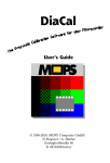
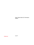
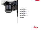
1
KF 2
ICS
Transmitted Light Microscope
Operating Manual
Carl Zeiss
KF 2 ICS
Knowledge of this manual is required for the operation of the instrument. Would you therefore please
make yourself familiar with the contents of this manual and pay special attention to hints concerning the
safe operation of the instrument.
The specifications are subject to change; the manual is not covered by an update service.
©
Unless expressly authorized, forwarding and duplication of this document, and the utilization and
communication of its contents are not permitted. Violations will entail an obligation to pay
compensation.
All rights reserved in the event of granting of patents or registration of a utility model.
Issued by:
Carl Zeiss
Microscopy
D-07740 Jena
Phone:
++49-36 41 64-16 16
Telefax:
++49-36 41 64-31 44
E-mail:
[email protected]
Internet:
www.zeiss.de/micro
Number of this manual: B 40-028 e
Date of issue: 10/97
II
B 40-028 e 10/97
KF 2 ICS
Carl Zeiss
CONTENTS
Page
INTRODUCTION ................................................................................................................. I
Title page ............................................................................................................................ I
Copyright ........................................................................................................................... II
Contents ............................................................................................................................III
Notes on instrument safety ................................................................................................ IV
Notes on warranty ..............................................................................................................V
Overall view....................................................................................................................... VI
1
1.1
1.2
1.3
1.4
DESCRIPTION ................................................................................................................. 1-3
Terms, intended use ........................................................................................................ 1-3
Instrument description ..................................................................................................... 1-3
Modules .......................................................................................................................... 1-4
Technical data ................................................................................................................. 1-6
2
2.1
START-UP....................................................................................................................... 2-3
Installation of the instrument ........................................................................................... 2-3
3
3.1
3.2
3.3
3.4
3.5
3.6
3.7
3.8
3.9
OPERATION ................................................................................................................... 3-3
Objective selection........................................................................................................... 3-3
Visual overall magnification.............................................................................................. 3-4
Eyepiece reticles............................................................................................................... 3-4
Setting the microscope in brightfield ................................................................................ 3-6
Setting the microscope for phase contrast........................................................................ 3-8
Setting the microscope in darkfield ................................................................................ 3-10
Photomicrography ......................................................................................................... 3-11
Videomicroscopy ........................................................................................................... 3-12
illumination via mirror and condensor 0.9 AS ................................................................. 3-12
4
4.1
4.2
CARE, MAINTENANCE AND TROUBLESHOOTING ........................................................ 4-3
Care and maintenance of the instrument ......................................................................... 4-3
Troubleshooting and requesting service............................................................................ 4-4
ANNEX .......................................................................................................................... A-1
List of abbreviations........................................................................................................ A-3
Physical and technical units ............................................................................................. A-4
EC conformity declaration............................................................................................... A-5
Certification in accordance with DIN EN ISO 9001 / DIN EN 46001 ................................... A-7
B 40-028 e 10/97
III
Carl Zeiss
KF 2 ICS
Notes on instrument safety
The KF 2 ICS microscope, including its original accessories, may only be used for the microscope
applications described in this manual.
The manufacturer cannot assume any liability for any other applications, possibly also involving
individual modules or single parts. This also applies to all service or repair work which is not
carried out by authorized service personnel. Furthermore, all guarantee/warranty claims also
expire for all those parts which were not directly affected by the repair.
Particular attention must be paid to the following warning notes:
The KF 2 ICS microscope was designed, produced and tested in compliance with DIN EN 61010-1
(IEC 1010-1), Safety requirements for electrical measuring, control and laboratory instruments, and
meets the requirements of appendix I of directive 73/23/EC and the relevant CSA and UL directives. The
instrument meets the requirements of the EC directive 89/336/EC and the EMC legislation of November
9th 1992. This operation manual includes information and warnings which must be observed by the
user.
The KF 2 ICS microscope is categorized as Protection Class I and has been allocated the
protection degree IP 20. The power plug must be inserted in a properly installed socket
featuring a grounding contact. The grounding effect must not be made ineffective by an
extension cable which does not have a protective ground wire.
Before switching on the instrument, check whether it is suitable for the line voltage present.
The voltage is indicated on the underside of the microscope stand. Incorrect voltage settings
can destroy the instrument.
If it is established that the protection measures are no longer effective, the instrument must be
switched off and safeguarded against inadvertent operation. For the repair of the KF 2 ICS
microscope, please contact the Carl Zeiss Microscopy Service in Germany (see page 4-6) or your
local Carl Zeiss agency.
Dust and dirt can impair the performance of the KF 2 ICS microscope. Therefore, protect the
instrument against these influences as far as possible. If the microscope will not be used for
longer periods of time (more than 6 hours), it must be protected using the dust cover.
IV
B 40-028 e 10/97
KF 2 ICS
Carl Zeiss
The instrument must be operated by trained personnel only, who must be aware of the
possible danger involved with microscopy and the relevant application.
The KF 2 ICS microscope is an optical precision instrument which can be impaired in its
performance or damaged when handled improperly.
All repairs inside the instrument may only be performed by the Carl Zeiss Microscopy Service in
Germany (see page 4-6) or your local Carl Zeiss agency.
Notes on warranty:
The manufacturer guarantees that the instrument has no material and production defects
when delivered. You must inform us of any defects immediately and we must do anything to
minimize the damage. If the manufacturer is informed of such a defect, he is obliged to
remove it; it is his decision whether he does this by repairing the instrument or by delivering an
instrument free of any defect. No guarantee is provided for defects caused by natural wear
(wearing parts in particular).
The instrument manufacturer is not liable for damage caused by faulty operation, negligence
or any other meddling with the instrument, or the use of accessories from other
manufacturers. This forfeits all the claims against warranty.
With the exception of the work specified in this manual, no maintenance or repair of the KF 2
ICS may be performed. Repairs may only be performed by Carl Zeiss Microscopy Service staff or
specially authorized personnel. Should any defect occur with the instrument, please contact the
Carl Zeiss Microscopy Service in Germany (see page 4-6) or your local Carl Zeiss agency..
B 40-028 e 10/97
V
Carl Zeiss
KF 2 ICS
Overall view of the KF 2 ICS microscope
VI
B 40-028 e 10/97
KF 2 ICS
Carl Zeiss
DESCRIPTION
Contents
1
1.1
1.2
1.3
1.4
DESCRIPTION .................................................................................................................1-3
Terms, intended use ........................................................................................................1-3
Instrument description .....................................................................................................1-3
Modules ..........................................................................................................................1-4
Technical data .................................................................................................................1-6
List of illustrations
Fig. 1-1
KF 2 ICS microscope equipment........................................................................................1-4
B 40-028 e 10/97
1-1
Carl Zeiss
1-2
KF 2 ICS
B 40-028 e 10/97
KF 2 ICS
Carl Zeiss
1
DESCRIPTION
1.1
Terms, intended use
Manufacturer's name: KF 2 ICS microscope
The KF 2 ICS microscope is a universal microscope for the visualization of fine structures and forms in
biology and medicine. These are typical application fields of this microscope:
-
Schools, universities
-
Medicine (for diagnosis)
-
Quality inspection
1.2
Instrument Description
The KF 2 ICS microscope is a small, compact instrument which permits high-performance transmittedlight microscopy at little effort.
Major features:
-
Sturdy, compact stand
-
Coaxial coarse and fine drive
-
Microscope stage with optional stand configuration:
Fixed stage with spring clamps or mechanical stage 75 25 with specimen holder L or mechanical
stage 75 25 with specimen holder R
-
Condenser 0.9 AS with aperture diaphragm for low-power observation
-
4-position nosepiece with W 0.8 thread
-
ICS objectives
-
Binocular tube 45°/20 ICS
-
Built-in illuminator with 6V 10W halogen lamp
-
Power unit with integrated, stabilized power supply
-
12 V battery operation on request
-
Illumination using external light source possible via mirror
B 40-028 e 10/97
1-3
Carl Zeiss
KF 2 ICS
1.3
Modules
Fig. 1-1
KF 2 ICS microscope equipment
1-4
B 40-028 e 10/97
KF 2 ICS
Carl Zeiss
KF 2 ICS microscope equipment
Cat. No.
KF 2 ICS microscope stand with 4-position W 0.8 nosepiece,
condenser 0.9 AS with aperture diaphragm and additional lens for
low-power observation, built-in illuminator, stabilized power
supply, power cable with safety plug or American flat plug,
2 halogen lamps 6V/10W and instrument protection cover.
1.1
KF 2 ICS stand equipment with fixed stage and 2 spring clamps
(230 V)
KF 2 ICS stand equipment with fixed stage and 2 spring clamps
(115 V)
450719-9901-000
KF 2 ICS stand equipment with mechanical stage 75 25 L and
specimen holder with spring clip R (230 V)
KF 2 ICS stand equipment with mechanical stage 75 25 L and
specimen holder with spring clip R (115 V)
450713-9901-000
2
Binocular tube 45°/20 ICS
452928-0000-000
3.1
Eyepiece PL 10/18 Br. foc.
444132-9901-000
3.2
Eyepiece PL 10/18 Br.
444131-9901-000
4.1
CP-"Achromat" objective 5/0.12
440920-0000-000
4.2
CP-"Achromat" objective 10/0.25
440930-0000-000
4.3
CP-"Achromat" objective 40/0.65
440950-0000-000
4.4
CP-"Achromat" objective 100/1.25 Oil
440980-0000-000
4.5
CP-"Achromat" objective 40/0.65 Ph 2 (alternative to 440950)
Ph 2 equipment
Diopter d = 30 mm
440951-0000-000
465214-0000-000
444020-0000-000
5
Instrument protection cover
1.2
B 40-028 e 10/97
450720-9901-000
450714-9901-000
1-5
Carl Zeiss
1.4
(1)
KF 2 ICS
Technical Data
Dimensions
Dimensions (width depth height) ......................................................................185 185 400 mm
(2)
Weight
Stand equipment................................................................................................................. approx. 3 kg
Binocular tube 45°/20 ICS.................................................................................................... approx. 1 kg
KF 2 ICS microscope, complete ............................................................................................. approx. 5 kg
(3)
Ambient conditions
Storage and transport (in packaging):
Permissible ambient temperature ....................................................................................... -40 to +70° C
Permissible relative humidity (without condensation) .............................................................max. 100 %
Operation:
Permissible ambient temperature ...................................................................................... +10 to +40° C
Permissible relative humidity (without condensation) ...............................................................max. 90 %
(4)
Operating data
Category of use.................................................................................................................. closed rooms
Protection class................................................................................................................................ SK 1
Protection degree ............................................................................................................................ IP 20
Electrical safety.................................................................in compliance with DIN EN 61010 (IEC 1010-1)
including CSA and UL directives
Pollution degree ................................................................................................................................... 2
Excess voltage category .........................................................................................................................II
Radio interference suppression....................................................... in accordance with EN 55011, Class B
Line voltage....................................................................................................... 100 to 127 VAC (10%)
or 220 to 240 VAC (10%)
Line frequency...........................................................................................................................50/60 Hz
Label of voltage range ....................................................................................... on instrument underside
max. power consumption .............................................................................................................. 35 VA
battery supply voltage ................................................................................................................12 V DC
(5)
Light source
Built-in illuminator system with halogen lamp............................................................................ 6 V, 10W
Lamp voltage (variable) .......................................................................................................0 to max. 6 V
(6)
Opto-mechanical data
Stand with objective focusing ..........................................................coaxial coarse (fine drive, lift: 15 mm
coarse drive: 1 rotation = 4 mm, fine drive: step-down ratio 1:10
Objective change..................................................................... manually via 4-position nosepiece W 0.8"
Largest possible eyepiece field...................................................................................................... 20 mm
Largest possible object field ........................................................................................................... 5 mm
Binocular tube ................................................. interpupillary distance can be set between 55 and 75 mm
1-6
B 40-028 e 10/97
KF 2 ICS
Carl Zeiss
START-UP
Contents
2
2.1
START-UP.......................................................................................................................2-3
Installation of the instrument ...........................................................................................2-3
List of illustrations
Fig. 2-1
Fig. 2-2
Fig. 2-3
Fig. 2-4
Fig. 2-5
Fig. 2-6
Attachment of binocular tube ..........................................................................................2-3
Positions of binocular tube...............................................................................................2-3
Screwing in objectives......................................................................................................2-4
Attachment of eyepieces .................................................................................................2-4
Switch on line operation mode ........................................................................................2-5
Switch on line/battery operation mode.............................................................................2-6
B 40-028 e 10/97
2-1
Carl Zeiss
2-2
KF 2 ICS
B 40-028 e 10/97
KF 2 ICS
Carl Zeiss
2
START-UP
2.1
Installation of the instrument
The KF 2 ICS microscope, including accessories, is delivered in standard packaging. We would
recommend you to keep the packaging material so that the instrument can be stored for a longer period
of time or returned to the manufacturer.
(1)
Preparations
Remove the microscope from the transport case and place it on the worktable.
(2)
Attachment of binocular tube 45°/20 ICS
Loosen hexagonal screw (2-1/2) using the SW 3
ball-headed screwdriver. Slightly incline the tube
(2-1/1) and insert it into the stand via its dovetail.
Turn the tube in the required observation position
and tighten the hexagonal screw.
Fig. 2-1
Attachment of binocular tube
Fig. 2-2
Positions of the binocular tube
The eyepiece distance is matched to the
individual interpupillary distance by swinging
the eyepiece tubes symmetrically towards one
another.
A higher (2-2/A) or lower (2-2/B) viewing height
is achieved by swiveling the tube.
B 40-028 e 10/97
2-3
Carl Zeiss
KF 2 ICS
(3)
Screwing in objectives
Remove dust caps (2-2/2) according to the number
of objectives and screw objectives (2-2/3) in
nosepiece clockwise one by one, starting with the
lowest magnification.
Nosepiece eyes which are not
required should be closed with dust
caps.
Fig. 2-3
Screwing in objectives
(4)
Inserting the eyepieces
Remove both protection caps (2-4/1) from the
binocular tube (2-4/2).
Insert the fixed eyepiece PL 10x/18 Br. (2-4/3) in
the right tube and the focusing eyepiece
PL 10x/18 Br. foc. (2-4/4) in the left tube.
The focusing eyepiece is used to
compensate for myopia of both eyes.
Fig. 2-4
2-4
Inserting the eyepieces
B 40-028 e 10/97
KF 2 ICS
(5)
Carl Zeiss
Switching on the line and line/battery modes
The illumination system of the KF 2 ICS has been designed for operation using a power unit,
but is also available for line/battery operation on request. Subsequent conversion from line
operation to line/battery operation is not possible.
View the type label (4-2/2) to check whether the built-in lamp supply complies with the present
line voltage.
Should the line voltage not lie within the range of the built-in lamp supply, please get in touch
with the nearest Carl Zeiss agency.
a)
Switch on line operation
Connect instrument to the power plug via the
power cable.
Set the required brightness via the control
(2-5/2).
Depending on requirements, place attenuation
filter or conversion filter on support (2-5/3).
Swing required objective (2-5/1) in the beam
path.
Fig. 2-5
B 40-028 e 10/97
Switching on the line operation
2-5
Carl Zeiss
b)
KF 2 ICS
Switch on the line/battery operation
Fig. 2-5
Switching on the line/battery operation
Line operation
Connect KF 2 ICS to line plug via line cable.
Set switch (2-6/4) to "Mains ON".
Set the required brightness using the "Dimmer Mains" control (2-6/2).
Battery operation:
Connect plug (2-6/10) of the "Control panel for battery" to socket (2-6/5).
Set switch (2-6/4) on the Standard KF 2 ICS in position "Battery ON".
Set switch (2-6/7) on the "Control panel for battery" in position "Battery off".
Connect "Control panel for battery" to car battery (12 V DC) via connection clamps (2-6/6).
Note the correct polarity of the connection clamps!
Set switch (2-6/7) on the "Control panel for battery" in position "Battery on".
The green LED (2-6/8) lights up.
Set the required brightness using the "Dimmer Battery" control (2-6/9).
Depending on requirements, place attenuation filter or conversion filter on support (2-6/3).
Swing required objective (2-6/1) in the beam path.
2-6
B 40-028 e 10/97
KF 2 ICS
Carl Zeiss
OPERATION
Contents
3
3.1
3.2
3.3
3.4
3.5
3.6
3.7
3.8
3.9
OPERATION ...................................................................................................................3-3
Objective selection...........................................................................................................3-3
Visual overall magnification..............................................................................................3-4
Eyepiece reticles...............................................................................................................3-4
Setting the microscope in brightfield ................................................................................3-6
Setting the microscope for phase contrast ........................................................................3-8
Setting the microscope in darkfield ................................................................................ 3-10
Photomicrography ......................................................................................................... 3-11
Videomicroscopy ........................................................................................................... 3-12
Illumination via mirror and condenser 0.9 AS................................................................. 3-12
List of illustrations
Fig. 3-1
Fig. 3-2
Fig. 3-3
Fig. 3-4
Fig. 3-5
Fig. 3-6
Fig. 3-7
Fig. 3-8
Fig. 3-9
Inserting an eyepiece reticle .............................................................................................3-4
Setting the condenser lever..............................................................................................3-6
Setting the microscope in brightfield ................................................................................3-7
Setting the microscope for phase contrast........................................................................3-8
Setting the Ph rings via diopter or auxiliary microscope .....................................................3-8
Illustration of the phase stop setting ................................................................................ 3-9
Setting the microscope in darkfield ................................................................................ 3-10
Attaching a SLR camera (CONTAX 167 MT).................................................................... 3-11
Illumination via mirror and condenser 0.9 AS.................................................................. 3-12
B 40-028 e 10/97
3-1
Carl Zeiss
3-2
KF 2 ICS
B 40-028 e 10/97
KF 2 ICS
Carl Zeiss
3
OPERATION
3.1
Choice of objectives
The objectives are the centerpiece of the microscope. The following is an example of how objectives can
be labeled:
CP-"Achromat" 10/0.25 /where
10
=
objective magnification
0.25
=
numerical aperture
=
infinite tube length
-
=
usable for covered and uncovered specimens
=
only for covered specimens with a cover slip thickness of 0.17 mm
or
0.17
The objective magnification multiplied with the eyepiece magnification (minimum 10x) results in the
visual overall magnification: e.g. 10 10 = 100.
The numerical aperture 1000, e.g. 0.25 1000 = 250, is the highest useful magnification, i.e. no
further details are resolved above that limit.
The ""sign means that these objectives cannot be used with microscopes the objectives of
which are labeled with "160" for the mechanical tube length.
B 40-028 e 10/97
3-3
Carl Zeiss
KF 2 ICS
3.2
Visual overall magnification
The MM visual overall magnification of the microscope results from the multiplication of the MObj
objective magnification with the Meyep. eyepiece magnification:
Example:
3.3
=
40
Meyep. =
10
MM
40 10 = 400
MObj
=
Eyepiece reticles
The 40 objective mentioned in the example under 3.2 produces an intermediate image of the object
with the magnification 40 : 1.
For quantitative assessment, this intermediate image can be superimposed with an eyepiece reticle,
where both the intermediate image and the eyepiece reticle are viewed through the focusing eyepiece.
(1)
Inserting the eyepiece reticle ( 26 mm)
The eyepieces PL 10/18 Br. foc. have been
designed for use with eyepiece reticles.
The slight image shift caused by the additional
path through the glass is taken into account on
the diopter scale by the fact that the zero point
position is indicated not by the white dot W but
by the red dot R.
The eyepiece reticles (3-1/1) have been adhered
to screw-in mounts (3-1/2) by the manufacturer
to allow easy replacement.
To replace a reticle, unscrew the screw-on
Fig. 3-1
Inserting an eyepiece reticle
mount or the part containing the eyepiece
reticle and replace it with the required one.
If eyepiece reticles are inserted into the unscrewed mount by the customer, attention must be
paid to the labeling being visible the right way up after insertion.
3-4
B 40-028 e 10/97
KF 2 ICS
(2)
Carl Zeiss
Compensating for myopia
Two focusing eyepieces PL 10/18 Br. foc. are required to allow the user to compensate for differences
in the visual performance of his two eyes.
Use the eyelens of the focusing eyepiece to focus on the line figure of the eyepiece reticle; focus on
the edge of the field of view if no eyepiece reticle is used.
Focus on the microscope image of a specimen via the focusing drive by looking through the eyepiece
with reticle.
When the image and the eyepiece reticle are in focus in the above eyepiece, focus the image for the
second eye via the eyelens of the second eyepiece.
The position of the focusing drive on the stand must not be changed.
B 40-028 e 10/97
3-5
Carl Zeiss
3.4
KF 2 ICS
Setting the microscope in brightfield
Place specimen on the sample stage with the cover slip pointing upwards.
The condenser 0.9 AS (3-2/3) is aligned with
the specimen stage and firmly attached to it. It
contains an aperture diaphragm to control the
image contrast. The condenser lever (3-2/1) is
attached to the bottom of the condenser via a
knurled knob (3-2/4).
Swing in the 10x objective. When using an
objective with magnification 10 or higher,
switch the condenser lever (3-2/1) to free
passage by turning the lever (3-2/2) to the right
until stop.
Fig. 3-2
Setting the condenser lever
The condenser lever (3-2/1) can be switched in two stop positions:
Lever (3-2/2) to the right:
free passage (to be used for objectives 10).
Lever (3-2/2) to the left:
additional lens swung in (to be used for objectives < 10).
The aperture diaphragm can also be set to both stop positions via the lever (3-2/2).
Turning to the right within the stop position:
aperture diaphragm is opened
Turning to the left within the stop position:
aperture diaphragm is closed.
3-6
B 40-028 e 10/97
KF 2 ICS
Carl Zeiss
Look through the fixed eyepiece of the
binocular tube first and focus on the object via
the focusing drive (3-3/2). Then set the focus
for the other eye by turning the eyelens of the
focusing eyepiece (3-3/1). Set the distance of
the tubes in such a way that you can see a
sharply limited field of view with both eyes.
Control the image contrast and the resolving
power via the condenser (aperture) stop using
the lever (3-2/2). Remove an eyepiece from the
tube for checking. Look through the empty
tube. Approx. 2/3 of the diameter of the visible
objective aperture should be illuminated
through the condenser stop. When changing
the objective, be sure to match the aperture
diaphragm to the objective opening.
Adjust image brightness using control (3-3/3) or
Fig. 3-3
Setting the microscope in brightfield
filters on the mount (3-3/4).
When using objectives with a low magnification (< 10), swing the additional lens in the light path
using the lever (3-2/2) and open the condenser stop until it disappears behind the edge of the field of
view.
When using immersion objectives, e.g. CP Achromat 100/1.25 oil, always apply a drop of immersion
oil between the objective front lens and the specimen. For this, special immersion oil, which
guarantees the full performance of the objective, is supplied in an oiler. Make sure that there are no
bubbles between the specimen and the objective front lens, since this would reduce the image
quality.
Do not immerse the condenser front lens.
The objective mount of the immersion objectives can be locked by lifting and slightly turning it so that
the immersion objective can be swung in and out without touching an immersed cover slip. This
prevents the front lenses of dry objectives from dirt.
B 40-028 e 10/97
3-7
Carl Zeiss
3.5
KF 2 ICS
Setting the microscope for phase contrast
The condenser lever (3-2/1) can be exchanged
for a condenser lever with phase stop Ph 2 (46
52 14) (3-4/3).
For this, unscrew the knurled knob (3-2/4), pull
out the changer in downward direction, slide in
the new changer until stop and fix it via the
knurled knob.
Set the object in brightfield first. Switch the
lever (3-4/1) in the left position (free passage)
and then move the aperture diaphragm to the
right until it has a suitable opening (also see
section 3.4).
Swing in phase stop Ph 2 (3-4/3) by switching
Fig. 3-4
Setting the microscope for phase
contrast
the lever (3-4/1) in the right position. The
aperture diaphragm opens automatically.
Swing a phase contrast objective, e.g. CP
Achromat 40/0.65 Ph 2, in the light path.
Centering the phase stop Ph 2 in relation to the
objective Ph 2.
Insert the diopter (3-5/2) into the tube instead
of an eyepiece (3-5/3).
Fig. 3-5
3-8
Setting the Ph rings via diopter or
centering telescope
B 40-028 e 10/97
KF 2 ICS
Carl Zeiss
Turn the screws (3-4/2) to superimpose the
dark Ph ring on the bright ring. The dark phase
ring of the objective must fully cover the bright
illumination ring.
A centering telescope (3-5/1) can also be
inserted into the tube instead of a diopter. If a
centering telescope is used, its eyelens must be
shifted until the illuminating ring is in focus.
Insert the eyepiece (3-5/3) in the tube again.
Adjust the lamp brightness via control (3-3/3).
If required, place a green filter on the filter
mount (3-3/4) to enhance the contrast of the
phase contrast image.
Fig. 3-6
Illustration of the phase stop
setting
Optimum phase contrast requires extreme cleanliness! Therefore, clean the front lens of the
objective used, the visible condenser surface, the upper cover slip surface and the lower carrier
plate surface with particular care and make them free from grease.
B 40-028 e 10/97
3-9
Carl Zeiss
3.6
KF 2 ICS
Setting the microscope in darkfield
The condenser lever (3-2/1) can be exchanged
for a condenser lever with darkfield stop D 0.7)
(3-7/2).
For this, unscrew the knurled knob (3-2/4), pull
out the changer in downward direction, slide in
the new changer until stop and fix it via the
knurled knob.
Set the object in brightfield first. Switch the
lever (3-7/1) in the left position (free passage)
and then move the aperture diaphragm to the
right until it has a suitable opening (also see
section 3.4). For focusing, search for an object
spot featuring minimum structure (if need be, a
spot at the edge of the specimen).
Fig. 3-7
Setting the microscope in darkfield
Swing in darkfield stop Ph 2 (3-7/2) by
switching the lever (3-7/1) in the right position.
The aperture diaphragm opens automatically.
To optimize the darkfield setting, the darkfield
stop (3-7/2) can be adjusted in height until the
object appears as bright as possible and the
background as dark as possible.
Set maximum brightness via control (3-3/3).
Optimum darkfield requires extreme cleanliness. Therefore, clean the front lens of the objective
used, the visible condenser surface, the upper cover slip surface and the lower carrier plate
surface with particular care and make them free from grease.
3-10
B 40-028 e 10/97
KF 2 ICS
3.7
Carl Zeiss
Photomicrography
The KF 2 ICS microscope (with phototube) can be changed from observation to photography via the
pushrod (3-8/7). Special connectors and the T 2 adapter allow commercially available 35 mm SLR
cameras and special microscope cameras (e.g. MC 80 DX) to be attached to the camera port of the KF 2
ICS. For the use of the photomicrography equipment, please observe the relevant separate manuals in
addition to the information provided in this manual.
Assembly (e.g. CONTAX 167 MT)
Screw the T 2 adapter of the camera used on
the connector 2.5 for T 2 (3-8/4).
Attach the camera and fix the cable release
(3-8/1), if required.
Loosen the three hexagonal screws (3-8/6),
remove the dust cover (3-8/8) from the
phototube (3-8/5) and insert the premounted
unit A in the phototube.
Align the unit in the required position and
tighten the three hexagonal screws (3-8/6).
If focusing is not to be made via the
viewfinder of the camera, the
component with the photo reticle
must be screwed in the eyepieces
(also see section 3.3).
For detailed information on SLR
cameras please see manual G 42406/II entitled "35 mm SLR cameras
for
microscopes
and
stereomicroscopes".
Fig. 3-8
B 40-028 e 10/97
Assembly of a SLR camera
(CONTAX 167 MT)
3-11
Carl Zeiss
3.8
KF 2 ICS
Videomicroscopy
Various TV 60 adapters allow 1-chip black-and-white and color cameras to be attached to the KF 2 ICS
with phototube.
3.9
Illumination via mirror and condenser 0.9 AS
Align (turn and tilt) the flatfield surface of the
illumination mirror (3-9/2) until diffuse daylight
or the light of a separate lamp illuminates the
specimen homogeneously.
Adjust
the object
"brightfield".
as
described
under
Swing required objective (3-9/1) in the beam
path.
Fig. 3-9
3-12
Illumination via mirror and
condenser 0.9 AS
B 40-028 e 10/97
KF 2 ICS
Carl Zeiss
CARE, MAINTENANCE AND TROUBLESHOOTING
Contents
4
4.1
4.2
CARE, MAINTENANCE AND TROUBLESHOOTING ........................................................4-3
Care and maintenance of the instrument .........................................................................4-3
Troubleshooting and requesting service............................................................................4-4
List of illustrations
Fig. 4-1
Fig. 4-2
Fig. 4-3
Changing the fuse for line/battery operation ....................................................................4-4
Changing the halogen lamp.............................................................................................4-5
Adjusting the lamp coil ....................................................................................................4-5
B 40-028 e 10/97
4-1
Carl Zeiss
4-2
KF 2 ICS
B 40-028 e 10/97
KF 2 ICS
Carl Zeiss
4
CARE, MAINTENANCE AND TROUBLESHOOTING
4.1
Care and maintenance of the instrument
Maintenance of the KF 2 ICS is limited to the following operations:
• Cover the instrument with the dust cover after every use.
• Do not install instrument in a damp room.
• Remove dust from optical surfaces using a natural hair brush or a rubber blower.
• Remove stubborn dirt or fingerprints using commercially available optics cleaning cloths; if necessary
slightly moisten the cloths with petroleum ether. Clean the front lenses of the objectives using
petroleum ether, but do not use alcohol.
When using the KF 2 ICS in humid climatic zones, proceed as follows:
• Store the KF 2 ICS in bright, dry and well ventilated rooms with a humidity of less than 65%; store
particularly sensitive components and accessories, such as objectives and eyepieces, in a dry closet.
• When the equipment is stored in closed cases for a longer period of time, the growth of fungus can
be avoided by including cloths soaked in fungicide in the cases.
The risk of growth of fungus on opto-mechanical instruments always exists in the following conditions:
• Relative humidity of more than 75% and temperatures between +15° C and +35° C for more than
three days.
• Installation in dark rooms without air ventilation.
• Dust deposits and fingerprints on optical surfaces.
B 40-028 e 10/97
4-3
Carl Zeiss
4.2
KF 2 ICS
Troubleshooting and requesting service
Troubleshooting on the KF 2 ICS is limited to only a few actions:
• Checking the line voltage
• Changing the fuses for line/battery operation
• Change and adjustment of the 6 V / 10 W halogen lamp.
(1)
Checking the line voltage
• Make sure that the required line voltage is available.
• Check the line cable and plug for defects.
• If there are any visible defects or if the instrument does not function, have the lamp supply and the
line cable exchanged by an expert.
(2)
Changing the fuses for line/battery operation
The fuse holder at the rear of the "Control panel for battery" contains the T 4 A set of fuses.
• Disconnect the instrument from the battery
supply.
• Use a coin to unscrew the fuse holder (4-1/2)
and remove it from the mount (4-1/1).
• Remove defective set of fuses (4-1/3) from the
fuse holder (4-1/2).
• Replace defective set of fuses.
• Insert fuse holder in the mount (4-1/1) again
and tighten the screws using a coin. While
doing this, press against the spring of the fuse
holder.
Fig. 4-1
4-4
Changing the fuses for line/battery
operation
B 40-028 e 10/97
KF 2 ICS
(3)
Carl Zeiss
Change and adjustment of the 6 V / 10 W halogen lamp.
• Place the microscope on its side on the table.
• Loosen the knurled screw (4-2/1) and pull out
the illuminator (4-2/4).
• Remove the halogen lamp (4-3/1) from the
metal clamps (4-3/2).
• Use the plastic protection bag supplied by the
manufacturer to hold the lamp and insert the
lamp in the metal clamps (4-3/2). Remove the
fingerprints before switching on the lamp.
Adjusting the halogen lamp:
• For an exact adjustment, the lamp coil and its
reflection image must be parallel to each other
and be identical in size when looking on the
lamp and concave mirror. To achieve this,
loosen screw (4-2/3) and move halogen lamp
with mount (4-3/3) until the required setting
has been obtained.
Fig. 4-2
Changing the halogen lamp
Fig.4-3
Adjusting the lamp coil
• Retighten screw (4-2/3).
• Then turn screw (4-3/4) until the coil and its
reflection image appear identical in size (Fig.
4-3/6). After adjustment, insert the lamp
housing and tighten the knurled screw (4-2/1).
B 40-028 e 10/97
4-5
Carl Zeiss
(4)
KF 2 ICS
Requesting service
All repairs of mechanical, optical or electronic components inside the instrument and of the electrical
components of the KF 2 ICS may only be performed by Carl Zeiss service staff or specially authorized
personnel.
To ensure the optimum setting and trouble-free function of your microscope even for a longer period of
time, we would recommend you to conclude a service/maintenance contract with Carl Zeiss.
In the case of subsequent orders or when service is required, please get in touch with the Carl Zeiss
Microscopy Service in Germany or your local Carl Zeiss agency.
The Carl Zeiss Microscopy Service in Germany can be reached at the following addresses:
Telephone:
Fax:
e-mail:
0180 333 6333 (only available within Germany)
++49-73 64 20-4939
[email protected]
Further information is available under the following Internet address:
[email protected]
www.zeiss.de/micro
4-6
B 40-028 e 10/97
KF 2 ICS
Carl Zeiss
ANNEX
-
List of abbreviations .................................................................................................................... A-3
Physical and technical units ......................................................................................................... A-3
EC conformity declaration ........................................................................................................... A-5
Certification in accordance with DIN EN ISO 9001 / DIN EN 46001 ............................................... A-7
B 40-028 e 10/97
A-1
Carl Zeiss
A-2
KF 2 ICS
B 40-028 e 10/97
KF 2 ICS
Carl Zeiss
List of abbreviations
AS
aspheric
Br.
for eyeglass wearers
CCD
Charge-Coupled Device
CSA
Canadian Standards Association
d
diameter
DC
direct current
DIN
German industrial standards
DX
coding system for the storage of electronically legible information, e.g. film speed
EEC
European Economic Community
EN
European standards
FAA
free working distance
foc.
focusing
ICS
Infinity Color corrected System
IEC
International Electrotechnical Commission
IP
International Protection (protection type)
KF
combination fine drive (coaxial drive)
L
left
MC
Microscope Camera
OZ
item number in figures
Ph 1, 2, 3
phase contrast 1, 2, 3
PL
flatfield
R
right
SK
protection class
SLR
Single Lens Reflex (camera)
SW
width of key wrench
S/W
black-and-white
T 2 adapter
standardized objective adapter
TV
television
UL
Underwriters Laboratories
VDE
Association of German Electrotechnicians
W 0.8“0.8“ Whitworth thread
Physical and technical units
°C
V
W
"
degree Centigrade (0°C = 32°F)
Volt
Watt
inch (1" = 25.4 mm)
B 40-028 e 10/97
A-3
Carl Zeiss
A-4
KF 2 ICS
B 40-028 e 10/97