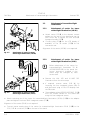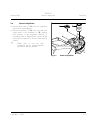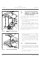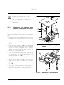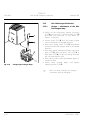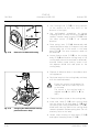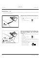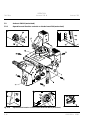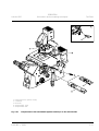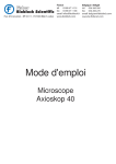
1
Operating Manual
Axiovert 200 / Axiovert 200 M
Inverted Microscopes
INTRODUCTION
Copyright
Carl Zeiss
Axiovert 200
Knowledge of this manual is required for the operation of the instrument. Would you please therefore
make yourself familiar with the contents of this manual and pay special attention to hints concerning the
safe operation of the instrument.
The specifications are subject to change; the manual is not covered by an update service.
©
Unless expressly authorized, forwarding and duplication of this document, and the utilization and
communication of its contents are not permitted. Violations will entail an obligation to pay
compensation.
All rights reserved in the event of granting of patents or registration of a utility model.
Issued by:
Carl Zeiss
Light Microscopy
P.O.B. 4041
37030 Göttingen
GERMANY
Phone :
++49 551 5060 660
Telefax:
++49 551 5060 464
Internet : www.zeiss.de/micro
E-Mail:
[email protected]
Number of this manual: B 40-080 e
Date of issue: 30.03.2001
0-2
B 40-080 e 03/01
INTRODUCTION
Contents
Axiovert 200
Carl Zeiss
CONTENTS
page
INTRODUCTION ........................................................................................................ 0-2
Copyright ...................................................................................................................0-2
Contents..................................................................................................................... 0-3
Notes on instrument safety.......................................................................................... 0-7
Notes on warranty .................................................................................................... 0-10
Overall view of the Axiovert 200................................................................................ 0-11
Overall view of the Axiovert 200 M............................................................................ 0-11
Microscopy in transmitted-light brightfield in a few steps ........................................... 0-12
CHAPTER 1
INSTRUMENT DESCRIPTION ..................................................................................... 1-3
1.1
Name and intended application ...................................................................................1-3
1.2
Instrument description and main features ....................................................................1-5
1.3
Microscope configurations and modules ......................................................................1-6
1.4
Objectives ................................................................................................................. 1-10
1.5
Eyepieces .................................................................................................................. 1-12
1.6
Condensers............................................................................................................... 1-12
1.7
Specimen stages and mounting frames...................................................................... 1-13
1.8
Binocular tubes ......................................................................................................... 1-13
1.9
Technical Data .......................................................................................................... 1-14
B 40-080 e 03/01
0-3
Carl Zeiss
INTRODUCTION
Contents
Axiovert 200
page
CHAPTER 2
START-UP.................................................................................................................. 2-5
2.1
Unpacking and installation of the microscope............................................................. 2-5
2.2
2.2.1
2.2.2
Attachment of binocular (photo) tube ......................................................................... 2-6
Inserting the eyepieces and the centering telescope.................................................... 2-6
Inserting the eyepiece reticle ....................................................................................... 2-7
2.3
2.3.1
2.3.2
Attachment of transmitted-light illumination ............................................................... 2-8
Attachment of carrier for transmitted-light illumination (100 W) .................................. 2-8
Attachment of carrier for transmitted-light illumination (30 W) .................................... 2-8
2.4
Screw in objectives ..................................................................................................... 2-9
2.5
2.5.1
2.5.4
2.5.5
Attachment of microscope stages ............................................................................. 2-10
Attachment of mechanical stage 130x85 R/L and mounting frame
for mechanical stage (K)............................................................................................ 2-10
Attachment of scanning stage................................................................................... 2-10
Attachment of specimen stage 250x230, object guide and mounting frame
for object guide (M) .................................................................................................. 2-11
Attachment of heating stage .................................................................................... 2-12
Attachment of gliding stage Z ................................................................................... 2-12
2.6
2.6.1
2.6.2
2.6.3
Attachment of condensers ........................................................................................ 2-13
Condensers for the Axiovert 200............................................................................... 2-13
Condensers from the Axioplan 2 imaging / Axioskop 2 product line ........................... 2-13
Changing the DIC prism in the condenser turret ........................................................ 2-14
2.7
2.7.1
2.7.2
2.7.3
2.7.4
Reflector turret ......................................................................................................... 2-15
Attachment of reflector turret................................................................................... 2-15
Equipment of reflector turret .................................................................................... 2-15
Changing the filter set in the FL reflector module ...................................................... 2-16
Changing the beam splitter in the FL reflector module ............................................... 2-16
2.8
Connection to the line .............................................................................................. 2-18
2.9
Interfaces of the Axiovert 200 M ............................................................................... 2-19
2.10
Switch microscope and ebq 100 dc power supply on and off..................................... 2-19
2.11
Equipotential bonding terminals ................................................................................ 2-19
2.12
2.12.1
2.12.2
2.12.3
2.12.4
HAL 100 halogen illuminator..................................................................................... 2-20
Change / attachment of the HAL 100 halogen lamp .................................................. 2-20
Coarse alignment of halogen illuminator ................................................................... 2-21
Attachment of halogen illuminator............................................................................ 2-21
Fine alignment of halogen illuminator ....................................................................... 2-22
2.5.2
2.5.3
0-4
B 40-080 e 03/01
INTRODUCTION
Contents
Axiovert 200
Carl Zeiss
page
2.13
2.13.1
2.13.2
2.13.3
2.13.4
Illuminator N HBO 103 .............................................................................................. 2-23
Attachment / change of the HBO 103 W/2 mercury pressure short-arc lamp............... 2-23
Coarse alignment of illuminator N HBO 103............................................................... 2-25
Attachment of illuminator N HBO 103 ....................................................................... 2-26
Fine adjustment of illuminator N HBO 103 using the adjusting aid.............................. 2-27
2.14
Attachment of Aqua Stop ......................................................................................... 2-28
CHAPTER 3
OPERATION............................................................................................................... 3-3
3.1
3.1.1
3.1.2
Axiovert 200 (manual) .................................................................................................3-4
Operation and function controls on the Axiovert 200 (manual)..................................... 3-4
Switching on and basic settings on the Axiovert 200 (manual).................................... 3-14
3.2
3.2.1
3.2.2
Axiovert 200 M (motorized)....................................................................................... 3-16
Operation and function controls on the Axiovert 200 (motorized)............................... 3-16
Switching on and basic settings on the Axiovert 200 M (motorized) ........................... 3-23
3.3
3.3.1
3.3.2
3.3.3
3.3.4
3.3.5
Illumination and contrasting techniques..................................................................... 3-28
Setting of transmitted-light brightfield for KÖHLER illumination.................................. 3-28
Setting of transmitted-light phase contrast ................................................................ 3-33
Setting of differential interference contrast (DIC) in transmitted light.......................... 3-35
Setting of VAREL contrast in transmitted light............................................................ 3-38
Setting of fluorescence contrast in reflected light ....................................................... 3-40
3.4
3.4.1
3.4.2
3.4.3
Documentation ......................................................................................................... 3-43
Image orientation of camera ports............................................................................. 3-43
Photomicrography with SLR camera........................................................................... 3-45
Photomicrography using a digital camera and videomicroscopy .................................. 3-46
B 40-080 e 03/01
0-5
Carl Zeiss
INTRODUCTION
Contents
Axiovert 200
page
CHAPTER 4
CARE, MAINTENANCE, TROUBLESHOOTING AND SERVICE.................................... 4-3
4.1
Care ........................................................................................................................... 4-3
4.2
4.2.1
4.2.2
4.2.3
Maintenance .............................................................................................................. 4-4
Performing checks ...................................................................................................... 4-4
Changing the fuses on the microscope........................................................................ 4-4
Changing the fuses on the ebq 100 dc power supply .................................................. 4-5
4.3
Service........................................................................................................................ 4-6
ANNEX ......................................................................................................................A-1
List of abbreviations ....................................................................................................A-3
List of key words.........................................................................................................A-5
Certification in accordance with DIN ISO 9001 / EN 46001
EC Declaration of Conformity
0-6
B 40-080 e 03/01
Axiovert 200
INTRODUCTION
Notes on instrument safety
Carl Zeiss
Notes on instrument safety
The Axiovert 200 / Axiovert 200 M microscopes were designed, produced and tested in compliance with
DIN 61010-1 (IEC 1010-1), Safety requirements for electrical measuring, control and laboratory
instruments, and meet the requirements of appendix I of directive 73/23/EC and the relevant CSA and UL
directives. The instruments meet the requirements of the EC directive 89/336/EC and the EMC legislation
of November 9th 1992. This operation manual includes information and warnings which must be
observed by the user.
The following warning and information symbols are used in this manual:
☞
NOTE
This symbol is a warning which you must observe under all circumstances.
CAUTION
This symbol is a warning which indicates a hazard to the instrument or instrument system.
CAUTION
This symbol is a warning which indicates a hazard to the user of the instrument.
CAUTION
Hot surface!
CAUTION
UV radiation is emitted!
CAUTION
Disconnect the instrument from the line before opening it!
B 40-080 e 03/01
0-7
Carl Zeiss
INTRODUCTION
Notes on instrument safety
Axiovert 200
The Axiovert 200 microscopes, including original accessories, may only be used for the microscope
techniques described in this manual.
Particular attention must be paid to the following notes:
The manufacturer cannot assume any liability for any other applications, possibly also involving
individual modules or single parts. This also applies to all service or repair work which is not
carried out by authorized service personnel. Furthermore, this forfeits all the claims against
warranty
The power plug must be inserted in a socket featuring a grounding (earth) contact. The
grounding effect must not be made ineffective by an extension cable which does not have a
protective ground wire.
If it is established that the protection measures are no longer effective, the instrument must be
switched off and safeguarded against inadvertent operation. For repair of the instrument,
contact the Carl Zeiss microscope service in Germany (see page 4-6) or your local Carl Zeiss
agency.
The Axiovert 200 microscopes are not equipped with any special devices for protection from
substances which are corrosive, toxic, radioactive or otherwise hazardous to health. All the
legal regulations for accident prevention, particularly those in the respective countries, must be
observed when handling such substances.
Before switching on the power unit for the HBO 50/100, check whether it is suitable for the
line voltage present.
Always disconnect the instrument from the line before opening the instrument and before
changing the fuses.
Make sure to use only fuses of the rated power required. The use of makeshift fuses and the
short-circuiting of the fuse holders are not permitted.
0-8
B 40-080 e 03/01
Axiovert 200
INTRODUCTION
Notes on instrument safety
Carl Zeiss
Gas discharge lamps, e.g. HBO 100, emit ultraviolet radiation which can cause burns on the
eyes and skin. Therefore, never look directly into the light of these lamps and avoid direct,
unprotected incidence of their light on your skin. When using the microscope, always use the
protective devices belonging to the instrument (e.g. special attenuation filters). When hot, gas
discharge lamps are under high internal pressure and must therefore be changed when cooled
down by using protective gloves and goggles (for detailed information, please see the
operating instructions B 40-065 e).
When fluorescence filters are used, the filter protecting from heat emitted by the microscope
illuminator must not be removed, since fluorescence filters are sensitive to heat and their
function might therefore be impaired.
Placing objects against or covering ventilation slats can lead to a build-up of heat which will
damage the instrument and, in extreme cases, cause a fire. Always keep the ventilation slats
clear and make sure that no objects enter the instrument through the ventilation slats.
Avoid touching the hot lamp housings. Always pull the power plug before changing the lamps
and allow the instrument to cool down for approx. 15 mins.
Dust and dirt can impair the performance of the instrument. Therefore, the instrument must be
protected against these influences as far as possible, and covered with the dust cover if it is not
used for longer periods of time. Always check whether the instrument is switched off before
you cover it.
The instruments may only be operated by trained personnel who must be aware of the possible
danger involved with microscopy and the relevant application.
The Axiovert 200 microscopes are opto-mechanical precision instruments which can be
impaired in their performance or damaged when handled improperly.
B 40-080 e 03/01
0-9
Carl Zeiss
INTRODUCTION
Notes on warranty
Axiovert 200
Notes on warranty
The manufacturer guarantees that the instrument has no material and production defects when
delivered. You must inform us of any defects immediately and we must do anything to minimize the
damage. If the manufacturer is informed of such a defect, he is obliged to remove it; it is his decision
whether he does this by repairing the instrument or by delivering an instrument free of any defect. No
guarantee is provided for defects caused by natural wear (wearing parts in particular) and improper use.
The instrument manufacturer is not liable for damage caused by faulty operation, negligence or any
other meddling with the instrument, particularly the removal or replacement of instrument components,
or the use of accessories from other manufacturers. This forfeits all the claims against warranty.
With the exception of the work specified in this manual, no maintenance or repair of the microscopes
may be performed. Repairs may only be performed by Carl Zeiss service staff or specially authorized
personnel. Should any defect occur with the instrument, please get in touch with the Carl Zeiss
microscopy service in Germany (see page 4-6) or your local Zeiss agency.
0-10
B 40-080 e 03/01
Axiovert 200
B 40-080 e 03/01
INTRODUCTION
Overall view of the Axiovert 200 and Axiovert 200 M
Carl Zeiss
0-11
Carl Zeiss
INTRODUCTION
Microscopy in transmitted-light brightfield in a few steps
Axiovert 200
Microscopy in transmitted-light brightfield in a few steps
☞
Before starting to use the Axiovert 200, make sure to read the notes on instrument safety and
the chapters entitled "Instrument Description" (Chapter 1) and "Start-up" (Chapter 2).
• Make the microscope ready for operation as described in chapter 2 and switch it on via the On/Off
switch (0-2/1).
• Select the objective with the lowest magnification (e.g. 10x) on the nosepiece (0-2/2). Set factor 1x on
the setting wheel (0-2/4) of the Optovar turret.
• Open the luminous-field diaphragm or the aperture diaphragm completely by pulling lever (0-2/16) to
the front until stop or by turning the setting wheel (0-2/20) to the front until stop.
• Turn the setting ring (0-2/19) to move the condenser turret in position H for brightfield (or DIC).
• Move reflector turret (0-2/5, if available) into the position without filter combination via the setting
ring.
• If required, remove analyzer slider (0-2/3) or switch to free light path.
• Turn setting wheel for Sideport right / left / vis (0-2/22) to position 100 % vis (visual
• Turn setting knob for Frontport / Baseport / vis (0-2/23) to position 100 % vis (
VIS
).
).
• Set beam splitting ratio to 100 % vis (0-2/10) on the tube. Switch off the Bertrand lens (if available).
).
Move combined rotary / slider knob (0-2/9) to position 100 % vis (
• Place a high-contrast specimen on the microscope stage (0-2/21). Adjust the binocular component.
• Use the coarse / fine focusing drive (0-2/6) to focus on the selected detail of the specimen. Should no
light be visible in the eyepieces, switch on the halogen illuminator via the HAL on / off switch (0-2/7).
• Use the toggle switch (0-2/8) to set the light
intensity to comfortable brightness.
Fig. 0-1
Diaphragm settings in transmittedlight brightfield according to
KÖHLER
• Close luminous-field diaphragm (0-2/16) until it
is visible in the field of view, even if not in focus
(0-1/A).
• Focus on the edge of the luminous-field
diaphragm (0-1/B) by moving the condenser
(0-2/17) vertically.
• Center (0-1/C) luminous-field diaphragm via the centering screws (0-2/15 and 18) and open it until
the edge of the diaphragm just disappears from the field of view (0-1/D).
• Remove one eyepiece from the eyepiece tube (or swing in Bertrand lens) and set aperture diaphragm
(0-2/20) to approx. 2/3 of the diameter of the objective exit pupil (0-1/E). Optimum contrast setting is
dependent on the respective specimen.
• Insert the eyepiece again (or swing out Bertrand lens) and refocus, if required, via the fine drive.
• After the microscope has been set to transmitted-light brightfield in this way, changing to this special
contrasting technique is now possible (see chapter 3 of this manual).
0-12
B 40-080 e 03/01
Axiovert 200
INTRODUCTION
Microscopy in transmitted-light brightfield in a few steps
1 On / Off switch
2 Objective nosepiece
3 Compartment for slider
Analyzer
4 Setting wheel for Optovar turret
5 Reflector turret
6 Focusing drive coarse / fine
7 HAL on / off switch
8 Toggle switch for illumination
intensity
9 Turning or sliding knob for
vis / doc beam splitting
Fig. 0-2
10 Turning or sliding knob for
Bertrand lens and manual shutter
11 Binocular tube component
12 Setting ring of the eyepiece
13 Eyepiece
14 Polarizer D with 2-position filter
changer
15 Centering screw for condenser
16 Setting lever for luminous-field
diaphragm
17 Setting knob for vertical
adjustment of the condenser
Carl Zeiss
18 Centering screw for condenser
19 Turret disk of condenser
20 Setting wheel for aperture
diaphragm on the condenser
21 Microscope stage
22 Compartment for aperture
diaphragm slider
23 Setting wheel for Sideport
24 Setting knob for Frontport /
Baseport
Axiovert 200
B 40-080 e 03/01
0-13
Carl Zeiss
0-14
INTRODUCTION
Microscopy in transmitted-light brightfield in a few steps
Axiovert 200
B 40-080 e 03/01
Axiovert 200
INSTRUMENT DESCRIPTION
Contents / List of illustrations
Carl Zeiss
INSTRUMENT DESCRIPTION
Contents
1
INSTRUMENT DESCRIPTION .......................................................................................... 1-3
1.1
Name and intended application........................................................................................1-3
1.2
Instrument description and main features.........................................................................1-5
1.3
Microscope configurations and modules...........................................................................1-6
1.4
Objectives...................................................................................................................... 1-10
1.5
Eyepieces....................................................................................................................... 1-12
1.6
Condensers ................................................................................................................... 1-12
1.7
Specimen stages and mounting frames .......................................................................... 1-13
1.8
Binocular tubes.............................................................................................................. 1-13
1.9
Technical Data ............................................................................................................... 1-14
List of illustrations
Fig. 1-1
Fig. 1-2
Fig. 1-3
Fig. 1-4
Microscope configurations and modules (sheet 1) ............................................................1-6
Microscope configurations and modules (sheet 2) ............................................................1-7
Microscope configurations and modules (sheet 3) ............................................................1-8
Microscope configurations and modules (sheet 4) ............................................................1-9
B 40-080 e 03/01
1-1
Carl Zeiss
1-2
INSTRUMENT DESCRIPTION
Contents / List of illustrations
Axiovert 200
B 40-080 e 03/01
Axiovert 200
INSTRUMENT DESCRIPTION
Name and intended application
1
INSTRUMENT DESCRIPTION
1.1
Name and intended application
Manufacturer's name:
Inverted microscope for transmitted light and epifluorescence
Brief name:
Axiovert 200
Axiovert 200 M
Carl Zeiss
(manual version)
(motorized version)
The Axiovert 200 microscopes fit in the product family of inverted transmitted-light microscopes as
follows:
Laboratory microscopes
Research microscopes
− Axiovert 25
− Axiovert 200
− Axiovert 25 C
− Axiovert 200 M
− Axiovert 25 CFL
The Axiovert 200 microscopes are universally applicable inverted microscopes and are mainly used for the
examination of cell and tissue cultures and of sediments in culture flasks, Petri dishes, microtiter plates,
etc. in transmitted and reflected light.
The Axiovert 200 microscopes permit the performance of the transmitted-light techniques brightfield,
phase contrast, differential interference contrast and VAREL contrast, and the epi-fluorescence
technique.
The microscopes Axiovert 200 and Axiovert 200 M are the basis for scientific microscopic work on living
cells.
− The sturdy stand provides attachment possibilities for various tools (micromanipulation), different light
sources, temperature control devices, etc.
− Ample space is available for the specimens and the relevant handling systems on account of the
inverted design, the LD illumination system of the microscope and the use of fixed stages. This
permits the performance of experiments which would not be possible with upright microscopes.
− The design allows the easy attachment of cameras, lasers, specific stages, etc.
B 40-080 e 03/01
1-3
Carl Zeiss
INSTRUMENT DESCRIPTION
Name and intended application
Axiovert 200
Typical fields of application:
Observation of intracellular processes in living cell cultures, cell/cell interactions, motility, growth,
measurements of potential, drug detection, microinjection, IVF (in-vitro fertilization), toxicity
examinations, patch-clamp technique, ion measurements, digital recording, long-time / time lapse
examinations in combination with the automation of processes, z-sectioning, deconvolution, visualization
of molecular structures, Fura (Ca measurement), GFP, optical tweezers and scissors, single molecule
detection, TIRF ....
Accessories for temperature control and incubation are described in the separate manual B 40-610 d/e,
"Incubation systems on the Axiovert".
1-4
B 40-080 e 03/01
Axiovert 200
1.2
INSTRUMENT DESCRIPTION
Instrument description and main features
Carl Zeiss
Instrument description and main features
The Axiovert 200 / Axiovert 200 M is available either as manual or as motorized version. The accessory
components are part of a modular system.
For documentation purposes, the Axiovert 200 / Axiovert 200 M can be equipped with the maximum of
five camera / TV ports in accordance with the customer's requests.
Adaptation possibilities are provided for heating stages, incubators and micromanipulators.
Major instrument features:
− ICS optics for image creation
− high thermal and mechanical stability
− high flexibility in documentation
− improved ergonomic design
− LCD display of instrument parameters
− 23 mm field of view
− Light Manager
− modular design for optimum adaptation to the relevant application
− 6-position nosepiece, coded
− 5-position reflector turret, manual: can be changed on both sides; motorized: can be changed from
the right
− 5-position or 6-position condenser turret
− 3-position Optovar turret
− changeable aperture diaphragm and luminous-field diaphragm sliders in reflected light
− fluorescence shutter
− illuminators: HAL 100 W, HBO 50, N HBO 103, N XBO 75
− Axiovert 200 M, all the major microscope functions are motorized.
B 40-080 e 03/01
1-5
Carl Zeiss
INSTRUMENT DESCRIPTION
Microscope configurations and modules
1.3
Microscope configurations and modules
Fig. 1-1
Microscope configurations and modules (sheet 1)
1-6
Axiovert 200
B 40-080 e 03/01
Axiovert 200
Fig. 1-2
INSTRUMENT DESCRIPTION
Microscope configurations and modules
Carl Zeiss
Microscope configurations and modules (sheet 2)
B 40-080 e 03/01
1-7
Carl Zeiss
Fig. 1-3
1-8
INSTRUMENT DESCRIPTION
Microscope configurations and modules
Axiovert 200
Microscope configurations and modules (sheet 3)
B 40-080 e 03/01
Axiovert 200
Fig. 1-4
INSTRUMENT DESCRIPTION
Microscope configurations and modules
Carl Zeiss
Microscope configurations and modules (sheet 4)
B 40-080 e 03/01
1-9
INSTRUMENT DESCRIPTION
Objectives
Carl Zeiss
1.4
Axiovert 200
Objectives
The objectives are the optical centerpiece of the microscope. The following is an example of how
objectives can be labelled:
A-Plan 10×/0.20 HD ∞/Key:
10×
objective magnification, with a color ring on the objective being allocated to each magnification
step (Zeiss color code)
0.20
numerical aperture
HD
reflected-light brightfield and darkfield objective
∞
infinite tube length
-
can be used without cover slip (D = 0 mm) or with cover slip thickness D = 0.17 mm
or
0
can only be used without cover slip (D = 0 mm)
0.17
can only be used with cover slip thickness D = 0.17 mm
and
Oil
oil immersion objective
Ph 2
phase contrast objective with a green color ring and phase stop Ph 2
Color ring code for objective magnification:
Color ring on black
objective
brown
red
orange
yellow
green
light
blue
dark
blue
Magnification 1.25×
factor
2.5×
4×; 5×
6.3×
10×
16×;20×; 40×; 50× 63×
25×; 32×
white
100×;
150×
The objective magnification (e.g. 10x) multiplied with the eyepiece magnification (e.g. 10x) and the
Optovar magnification (e.g. 1.6x) results in the visual overall magnification;
example: 10 x 10 x 1.6 = 160x.
The numerical aperture x 1000, e.g 0.20 x 1000 = 200x, is the highest useful magnification, i.e. no
further details are resolved above that limit.
In transmitted-light applications, the exact observance of the cover slip thickness of 0.17 mm is all the
more necessary the higher the numeric aperture of the objective. Therefore, so-called "corr" objectives
can be set for different cover slip thicknesses via a correction ring. For this, a specimen area is searched,
and the position of the correction ring where optimum focus and image contrast are obtained is
determined (refocusing is always required).
Immersion objectives are always insensitive to differences in cover slip thickness.
When immersion objectives are used, the air between the cover slip and the objective is replaced with a
liquid, which is immersion oil in most cases.
1-10
B 40-080 e 03/01
INSTRUMENT DESCRIPTION
Objectives
Axiovert 200
Carl Zeiss
The following objectives are available for the Axiovert 200 / Axiovert 200 M microscope:
Objective type
A-Plan
A-Plan
A-Plan
LD A-Plan
LD A-Plan
LD A-Plan
LD A-Plan
LD A-Plan
LD A-Plan
Cover slip cap
Magnification/
numeric aperture
5x/0.12
10x/0.20
20x/0.30
20x/0.30
32x/0.40
32x/0.35
40x/0.50
40x/0.50
Cover slip
thickness D in
mm
D = 0.6 - 1.4
D = 0.6 - 1.4
D = 0.6 - 1.4
D = 0.6 - 1.4
D = 0.7 - 1.3
D = 0.7 - 1.3
D = 0.17 - 0.6
Free working
distance A in
mm
Contrasting
Cat. No.
a = 9.1
a = 4.4
a = 4.3
a = 4.2
a = 3.1
a = 3.1
a = 2.3
a = 2.3
ph0
ph1 var1
ph1
ph1 var1
ph1
ph1 var1
ph2
ph2 var2
000000-1018-589
000000-1020-863
000000-1006-591
000000-1006-592
000000-1006-593
000000-1006-594
000000-1006-595
000000-1006-596
000000-1016-757
LD Achroplan *
Achroplan
Achroplan
LD Achroplan
LD Achroplan
LD Achroplan
LD Achroplan
LD Achroplan
4x/0.10
10x/0.25
20x/0.40
20x/0.40
40x/0.60
40x/0.60
63x/0.75
corr D = 0 - 1.5
corr D = 0 - 1.5
corr D = 0 - 2
corr D = 0 - 2
corr D = 0 - 1.5
a = 11.1
a = 4.8
a = 10.2
a = 10.2
a = 1.8
a = 1.8
a = 1.57
Plan-Neofluar
Plan-Neofluar
Plan-Neofluar
Plan-Neofluar
Plan-Neofluar
Plan-Neofluar
Plan-Neofluar
Plan-Neofluar
Plan-Neofluar
Plan-Neofluar
Plan-Neofluar
Plan-Neofluar
Plan-Neofluar
Plan-Neofluar
Plan-Neofluar
Plan-Neofluar
5x/0.15
5x/0.15
10x/0.30
10x/0.30
16x/0.50 Imm
16x/0.50 Imm
20x/0.50
20x/0.50
40x/0.75
40x/0.75
40x/1.30 Oil
40x/1.30 Oil
63x/0.95 Korr.
100x/1.30 Oil
100x/1.30 Oil
D = 0.17
D = 0.17
D = 0.17
D = 0.17
D = 0.17
D = 0.17
D = 0.17
D = 0.17
D = 0.17
D = 0.17
D = 0.17
D = 0.17
D = 0.17
a = 13.6
a = 13.6
a = 5.6
a = 5.6
a = 0.22
a = 0.22
a = 2.0
a = 2.0
a = 0.5
a = 0.5
a = 0.2
a = 0.2
a = 0.12
a = 0.12
a = 0.12
Plan-Apochromat
Plan-Apochromat
63x/1.40 Oil
D = 0.17
ph1
ph2
ph2
ph2
ph1
ph1
Ph1
ph2
ph2
ph3
ph3
440020-0000-000
440031-0000-000
440844-0000-000
440845-0000-000
440864-0000-000
440865-0000-000
440861-0000-000
440320-0000-000
440321-0000-000
440330-0000-000
440331-0000-000
440530-0000-000
440531-0000-000
000000-1004-072
000000-1004-989
440350-9902-000
440351-9902-000
000000-1022-818
000000-1022-819
440364-0000-000
000000-1018-595
000000-1031-171
440760-0000-000
* a refers to d = 1
B 40-080 e 03/01
1-11
INSTRUMENT DESCRIPTION
Eyepieces / Condensers
Carl Zeiss
1.5
Axiovert 200
Eyepieces
The following eyepieces are available for the Axiovert 200 and Axiovert 200 M:
Eyepiece type
Image angle
Cat. No.
Eyepiece W-PL 10×/23 Br. foc.
24.7°
455043-0000-000
Eyepiece W-PL 10×/23 Br. foc.
24.7°
000000-1016-758
Centering telescope d = 30
1.6
000000-1006-362
Condensers
The following condensers are available for combination with the stage carrier D and the transmitted-light
equipment on the Axiovert 200 / Axiovert 200 M:
Condenser type
Cat. No.
Comments
LD condenser 0.35, 5 positions:
H/DIC, Ph0, Ph1, Ph2, Var1/2
000000-1005-844
from objective 2.5x
LD condenser 0.55, 6 positions:
H, Ph1, Ph2, Ph3, DIC, DIC mot.
000000-1005-848
from objective 4x
Condenser 0.35, 6 positions:
H/DIC, Ph0, Ph1, Ph2, DIC, DIC
000000-1005-845
Condenser 0.55, 5 positions:
H, Ph1, Ph2, Ph3, Var1/2
000000-1005-846
Condenser 0.55, 6 positions:
H, Ph1, Ph2, Ph3, DIC, DIC
000000-1005-847
Condenser adapter for condensers 0.8
and 1.4
000000-1005-849
Condenser 0.8 H, D 0.66 / 0.8 Ph DIC,
plus factory-aligned: DIC prism III/0.8
445445-9901-000
445485-0000-000
Condenser 0.8 H, DIC, plus factoryaligned: DIC prism III/0.8
000000-1087-444
000000-1087-445
Condenser 1.4, 6 positions:
H, D, Ph 2x, DIC 2x
445453-0000-000
1-12
B 40-080 e 03/01
Axiovert 200
1.7
INSTRUMENT DESCRIPTION
Specimen stages and mounting frames / Binocular tubes
Carl Zeiss
Specimen stages and mounting frames
The Axiovert 200 microscopes can be equipped with the following specimen stages and mounting
frames:
Description
Cat. No.
Specimen stage 250x230 mm with ceramic surface and
3-point support
000000-1005-832
Object guide 130x85 right, can be attached on both 000000-1005-833
sides, accepts various mounting frames
Object guide 130x85 left, can be attached on both sides,
accepts various mounting frames
000000-1110-991
Mechanical stage 130x85 R/L
000000-1005-834
Mounting frame for object guide (M)
see price list
Mounting frame for mechanical stage (K)
see price list
Gliding stage Z
471722-0000-000
Scanning stage
000000-1113-509
1.8
Binocular tubes
The following tubes can be used with the Axiovert 200 microscopes:
Description
Cat. No.
VIEWING ANGLE Light distribution in
/
%
FIELD
NUMB
ER
Binocular tube 45°/23
000000-1005-827
45° / 23
100 %
Binocular phototube 45°/23,
with Bertrand lens and shutter
000000-1005-828
45° / 23
100-0, 0-100, 50-50
Binocular ergotube 25°/23
vertically variable,
with Bertrand lens and shutter
000000-1005-829
25° / 23
100 %
B 40-080 e 03/01
1-13
INSTRUMENT DESCRIPTION
Technical Data
Carl Zeiss
1.9
Axiovert 200
Technical Data
Dimensions (width x depth x height)
Stand Axiovert 200.................................................................................... approx. 295 × 805 × 707 mm
Weight
Axiovert 200 without fluorescence equipment ................................................................... approx. 26 kg
Axiovert 200 M with fluorescence equipment .................................................................... approx. 40 kg
Ambient conditions
Storage and transport (in packaging):
Permissible ambient temperature................................................................................... -40 to +50 °C
Operation:
Permissible ambient temperature.................................................................................. +10 to +35 °C
Permissible relative humidity (without condensation)...........................................................max. 80 %
Altitude of use ............................................................................................................... max. 2000 m
Atmospheric pressure......................................................................................... 800 hPa to 1060 hPa
Pollution degree............................................................................................................................... 2
Operating data
Category of use.................................................................................................................. closed rooms
Protection class.......................................................................................................................................I
Protection type ................................................................................................................................ IP 20
Electrical safety.................................................................in compliance with DIN EN 61010 (IEC 1010-1)
...............................................................................................................including CSA and UL directives
Excess voltage category .........................................................................................................................II
Radio interference suppression....................................................... in accordance with EN 55011, Class B
Voltage ranges:
Integrated 12 V, 100 W power unit, stabilized ............................................ 100 to 240 VAC (± 10 %)
1-14
B 40-080 e 03/01
Axiovert 200
INSTRUMENT DESCRIPTION
Technical Data
Carl Zeiss
Line frequency ...................................................................................................................... 50 to 60 Hz
Power consumption with internal power units
Axiovert 200 ...........................................................................................................................235 VA
Axiovert 200 M .......................................................................................................................235 VA
and external power units
Power supply N XBO 75, 100 ... 240 V AC ...............................................................................130 VA
Power supply N HBO 100, 90 ... 240 V AC...............................................................................265 VA
Fuses in accordance with IEC 127
Axiovert 200
100 ... 240 V AC ....................................................................................T 4.0 A/H; 250 V; 5 × 20 mm
Axiovert 200 M
100 ... 240 V AC ....................................................................................T 4.0 A/H; 250 V; 5 × 20 mm
Light sources
HBO 50 W/AC mercury pressure short-arc lamp
Lamp voltage for lamp type L1 and L2 .................................................... L1: 39 ... 45 V/L2: 34 ... 39 V
Power ........................................................................................................................................50 W
Average life............................................................................................................................... 100 h
HBO 103 mercury vapor short-arc lamp.........................................................................................100 W
Opto-mechanical data
Stand with stage focusing ............................................................................ with coarse drive (5 mm/rot)
and fine drive (0.1 mm /rot)
Fine scaling 1 µm/scale part
Overall lift approx. 10 mm
Objective change ................................................................................................via 6-position nosepiece
Objectives......................................................................................................with W 0.8" x 1/36"thread
Eyepieces .................................................................................................. with plug-in diameter 30 mm
and............................................................................................................................field number 23
B 40-080 e 03/01
1-15
Carl Zeiss
1-16
INSTRUMENT DESCRIPTION
Technical Data
Axiovert 200
B 40-080 e 03/01
Axiovert 200
START-UP
Contents
Carl Zeiss
START-UP
Contents
2
START-UP....................................................................................................................... 2-5
2.1
Unpacking and installation of the microscope..................................................................2-5
2.2
2.2.1
2.2.2
Attachment of binocular (photo) tube ..............................................................................2-6
Inserting the eyepieces and the centering telescope......................................................... 2-6
Inserting the eyepiece reticle ............................................................................................ 2-7
2.3
2.3.1
2.3.2
Attachment of transmitted-light illumination ....................................................................2-8
Attachment of carrier for transmitted-light illumination (100 W) ....................................... 2-8
Attachment of carrier for transmitted-light illumination (30 W) ......................................... 2-8
2.4
Screw in objectives ..........................................................................................................2-9
2.5
2.5.1
2.5.4
2.5.5
Attachment of microscope stages .................................................................................. 2-10
Attachment of mechanical stage 130x85 R/L and mounting frame
for mechanical stage (K) ................................................................................................ 2-10
Attachment of scanning stage ....................................................................................... 2-10
Attachment of specimen stage 250x230, object guide and mounting frame
for object guide (M)....................................................................................................... 2-11
Attachment of heating stage ......................................................................................... 2-12
Attachment of gliding stage Z........................................................................................ 2-12
2.6
2.6.1
2.6.2
2.6.3
Attachment of condensers ............................................................................................. 2-13
Condensers for the Axiovert 200.................................................................................... 2-13
Condensers from the Axioplan 2 imaging / Axioskop 2 product line ................................ 2-13
Changing the DIC prism in the condenser turret ............................................................. 2-14
2.7
2.7.1
2.7.2
2.7.3
2.7.4
Reflector turret .............................................................................................................. 2-15
Attachment of reflector turret........................................................................................ 2-15
Equipment of reflector turret ......................................................................................... 2-15
Changing the filter set in the FL reflector module ........................................................... 2-16
Changing the beam splitter in the FL reflector module.................................................... 2-16
2.5.2
2.5.3
B 40-080 e 03/01
2-1
Carl Zeiss
START-UP
Contents
Axiovert 200
2.8
Connection to the line................................................................................................... 2-18
2.9
Interfaces of the Axiovert 200 M ................................................................................... 2-19
2.10
Switch microscope and ebq 100 dc power supply on and off ......................................... 2-19
2.11
Equipotential bonding terminals .................................................................................... 2-19
2.12
2.12.1
2.12.2
2.12.3
2.12.4
HAL 100 halogen illuminator ......................................................................................... 2-20
Change / attachment of the HAL 100 halogen lamp....................................................... 2-20
Coarse alignment of halogen illuminator........................................................................ 2-21
Attachment of halogen illuminator ................................................................................ 2-21
Fine alignment of halogen illuminator ............................................................................ 2-22
2.13
2.13.1
2.13.2
2.13.3
2.13.4
Illuminator N HBO 103 .................................................................................................. 2-23
Attachment / change of the HBO 103 W/2 mercury pressure short-arc lamp................... 2-23
Coarse alignment of illuminator N HBO 103................................................................... 2-25
Attachment of illuminator N HBO 103 ........................................................................... 2-26
Fine adjustment of illuminator N HBO 103 using the adjusting aid .................................. 2-27
2.14
Attachment of Aqua Stop.............................................................................................. 2-28
2-2
B 40-080 e 03/01
Axiovert 200
START-UP
List of illustrations
Carl Zeiss
List of illustrations
Fig. 2-1
Fig. 2-2
Fig. 2-3
Fig. 2-4
Fig. 2-5
Fig. 2-6
Fig. 2-7
Fig. 2-8
Fig. 2-9
Fig. 2-10
Fig. 2-11
Fig. 2-12
Fig. 2-13
Fig. 2-14
Fig. 2-15
Fig. 2-16
Fig. 2-17
Fig. 2-18
Fig. 2-19
Fig. 2-20
Fig. 2-21
Fig. 2-22
Fig. 2-23
Fig. 2-24
Fig. 2-25
Fig. 2-26
Fig. 2-27
Fig. 2-28
Fig. 2-29
Fig. 2-30
Fig. 2-31
Fig. 2-32
Fig. 2-33
Fig. 2-34
Fig. 2-35
Fig. 2-36
Fig. 2-37
Fig. 2-38
Installation of microscope ................................................................................................2-5
Attachment of binocular tube ..........................................................................................2-6
Inserting the eyepieces.....................................................................................................2-6
Inserting the eyepiece reticle ............................................................................................2-7
Attachment of carrier for transmitted-light illumination (100 W) .......................................2-8
Attachment of carrier for transmitted-light illumination (30 W) .........................................2-8
Screw in objectives ..........................................................................................................2-9
Attachment of mechanical stage 130x85 ....................................................................... 2-10
Insertion of mounting frame (K) ..................................................................................... 2-10
Attachment of specimen stage 250x230 ........................................................................ 2-11
Attachment of object guide and mounting frame........................................................... 2-11
Attachment of heating stage ......................................................................................... 2-12
Attachment of condenser .............................................................................................. 2-13
Attachment of condenser adapter.................................................................................. 2-13
Changing the DIC prism................................................................................................. 2-14
Insertion of reflector turret............................................................................................. 2-15
Insertion of reflector modules ........................................................................................ 2-15
Changing the filter set in the FL reflector module ........................................................... 2-16
Changing the beam splitter............................................................................................ 2-16
Changing the beam splitter............................................................................................ 2-17
Axiovert 200 M (rear)..................................................................................................... 2-18
Power supply ebq 100 dc (rear)...................................................................................... 2-18
Axiovert 200 M (rear)..................................................................................................... 2-19
Power supply ebq 100 dc (front) .................................................................................... 2-19
Changing the halogen lamp........................................................................................... 2-20
Alignment of halogen illuminator................................................................................... 2-21
Attachment of halogen illuminator................................................................................. 2-21
Changing the diffusion disk ........................................................................................... 2-22
Power supply ebq 100 dc............................................................................................... 2-23
Removal of N HBO 103 housing ..................................................................................... 2-24
Changing the HBO 103 W/2 mercury pressure short-arc lamp......................................... 2-24
Coarse alignment of mercury vapor short-arc lamp......................................................... 2-25
Focal spots of N HBO 103 before coarse adjustment....................................................... 2-25
Focal spots of N HBO 103 after coarse adjustment ......................................................... 2-25
Attachment of illuminator N HBO 103............................................................................ 2-26
Power supply ebq 100 dc............................................................................................... 2-26
Adjusting aid and illuminator N HBO 103 ....................................................................... 2-27
Attachment of Aqua Stop .............................................................................................. 2-28
B 40-080 e 03/01
2-3
Carl Zeiss
2-4
START-UP
List of illustrations
Axiovert 200
B 40-080 e 03/01
Axiovert 200
2
START-UP
Unpacking and installation of microscope
Carl Zeiss
START-UP
On account of the complexity of the equipment and to ensure proper functioning, installation and initial
start-up of the Axiovert 200 or Axiovert 200 M at your site will be performed entirely by the responsible
Carl Zeiss agency.
The following major services will be performed:
− Installation of the microscope, assembly and alignment of all components (if these are not already
factory-aligned).
− Connection of cables and line connection.
− Instrument training
Should you want to install the instrument yourself or move it to another position, proceed as described
below.
2.1
Unpacking and installation of the microscope
The basic instrument is supplied in a commercially available polyethylene case in cardboard packaging.
This package contains the following: stand, binocular tube, objectives, eyepieces, condenser, halogen
illuminator, fluorescence illuminator and various small components such as filter and diaphragm slider,
DIC slider, dust cover, tools, etc.
Further, optional accessories are supplied in a separate case.
• Remove all components from the packaging
and use the delivery note to check for
completeness.
• Place stand (2-1/1) on a low-vibration, flat
worktable.
• Properly dispose of original packaging, or keep
it for storage or return of the instrument to the
manufacturer.
• Unscrew handle (2-1/2) using the SW 4 Allen
key.
Fig. 2-1
B 40-080 e 03/01
Installation of microscope
2-5
Carl Zeiss
START-UP
Attachment of binocular (photo)tube
2.2
Axiovert 200
Attachment of binocular (photo)
tube
All the binocular tubes listed in the microscope
configuration can be attached to the Axiovert 200
and Axiovert 200 M as described below.
Proceed as follows to attach a tube for the first
time, or to replace a tube:
Fig. 2-2
Attachment of binocular tube
•
Loosen hexagonal screw (2-2/2) using the SW3
ball-headed screwdriver. If a tube is to be
replaced, hold it and remove it in forward
direction.
•
Remove the dust cap from the tube lens of the
tube to be attached.
•
Insert dovetail of the binocular tube (2-2/1)
into the stand mount (2-2/3), align it with the
stand and tighten hexagonal screw (2-2/2)
using the ball-headed screwdriver.
2.2.1
Inserting the eyepieces
centering telescope
and the
• Remove both dust protection caps (2-3/1 and
4) from the binocular tube.
• Remove both eyepieces (2-3/2) from the cases
and insert them in the binocular tube until stop.
• The centering telescope (2-3/3), which is used
to view the aperture and phase stops and to
center the phase stops, can be inserted in one
of the tubes instead of an eyepiece. The
variable eyelens permits focusing on these
stops.
Fig. 2-3
☞
2-6
Inserting the eyepieces
The eyepieces W-PL 10x/23 Br. foc. can be attached to all tubes.
B 40-080 e 03/01
Axiovert 200
2.2.2
START-UP
Attachment of binocular (photo)tube
Carl Zeiss
Inserting the eyepiece reticle
The eyepieces W-PL 10x/23 Br. foc. are intended
for use with eyepiece reticles.
The slight image shift caused by the additional
path through the glass is taken into account on
the diopter scale by the fact that the zero point
position is indicated not by the white dot (2-4/W)
but by the red dot (2-4/R).
The eyepiece reticles (2-4/1) have been adhered to
screw-in mounts (2-4/2) by the manufacturer to
allow easy replacement.
To replace an eyepiece reticle, remove screw-in
mount (2-4/2) with eyepiece reticle (2-4/1) and
replace it with a screw-in mount containing the
required eyepiece reticle.
☞
Fig. 2-4
Inserting the eyepiece reticle
If eyepiece reticles are inserted into the unscrewed mount by the customer, attention must be
paid to the labelling being visible the right way up after insertion.
Compensation of ametropia when eyepiece reticles are used
For the correct use of an eyepiece reticle, two focusing eyepieces are required to allow the user to
compensate for differences in the visual performance of his two eyes.
• Use the focusing eyepiece to focus on the eyepiece reticle; focus on the edge of the field of view if no
eyepiece reticle is used.
• Use the focusing drive to focus on the microscope image of a specimen through the eyepiece set as
described above.
• Then use the second focusing eyepiece to focus the microscope image for the second eye. The
position of the focusing drive on the microscope stand must not be changed.
B 40-080 e 03/01
2-7
Carl Zeiss
START-UP
Attachment of transmitted-light illumination
Axiovert 200
2.3
Attachment of transmitted-light
illumination
2.3.1
Attachment of carrier for transmitted-light illumination (100 W)
•
•
Attach carrier (2-5/1) to the relevant contact
surface on the rear of the stand and use the
SW 4 Allen key to tighten the four enclosed
hexagonal screws (2-5/2).
Connect plug (2-5/4) for the LCD display (if
available) to the SB socket (2-5/3) at the
instrument rear.
Alignment of the carrier (100 W) is not required.
Fig. 2-5
Attachment of carrier for transmitted-light illumination (100 W)
2.3.2
Attachment of carrier for transmitted-light illumination (30 W)
Before attachment of the carrier for
transmitted-light illumination 30 W
(451380-0000-000) to the stand, the
control electronics included in the
stand must be changed by Zeiss
service staff.
Fig. 2-6
•
Attachment of carrier for transmitted-light illumination (30 W)
•
Remove the HAL 100 and N HBO 103
illuminators from the microscope.
•
If required, remove carrier (100 W) by
loosening the four hexagonal screws (SW 4)
and disconnect plug of the LCD display from
the SB socket.
•
Screw adapter plate (000000-1005-842, 2-6/1)
onto the contact surface on the stand rear
using the four hexagonal screws.
Attach centering pin of the carrier for transmitted-light illumination (30 W) (2-6/2) to the adapter
plate and tighten the three SW 4 hexagonal screws (2-6/3).
Alignment of the carrier (30 W) is not required.
•
2-8
Connect power supply plug of the carrier for transmitted-light illumination 30 W (2-6/5) to the
12 V / 100 W connector (2-6/4) on the rear of the stand.
B 40-080 e 03/01
Axiovert 200
2.4
START-UP
Screw in objectives
Carl Zeiss
Screw in objectives
• Remove dust caps (2-7/1) from the respective
openings in the nosepiece.
• Remove objectives (2-7/2) from the case and
screw them in the nosepiece (2-7/3), starting
with position 1 (see engraved number), in
increasing order of magnification factors. Make
sure that the objective is correctly and securely
locked.
☞
Make sure to use the dust
protection caps on those nosepiece
eyes which are not required.
Fig. 2-7
B 40-080 e 03/01
Screw in objectives
2-9
Carl Zeiss
START-UP
Attachment of microscope stages
Axiovert 200
2.5
Attachment of microscope stages
2.5.1
Attachment of mechanical stage
130x85 R/L and mounting frame
for mechanical stage (K)
The mechanical stage is mounted to the stand
directly above three contact points with the
relevant drilled holes.
• To improve access during stage assembly, the
carrier (2-8/3) for transmitted-light illumination
can be tilted backwards.
• Place mechanical stage (2-8/2) on the three
contact points (2-8/4) of the stand and fix it in
position using three hexagonal screws (2-8/1)
(two at the front, one at the rear).
Three countersunk holes each on the front and
rear of the mechanical stage 130x85 R/L permit
attachment with the drive knobs being positioned
on the right or on the left.
Fig. 2-8
Attachment of mechanical stage
130x85
• Then insert the mounting frame (K) (2-9/1) into
the mechanical stage.
For this purpose, position the red dot (2-9/2) of
the corner of the mounting frame on the red
dot of the mechanical stage (2-9/3) and press
the mounting frame diagonally against the
springs and downwards into the recess. Make
sure that the mounting frame is seated
correctly.
2.5.2
Attachment of scanning stage
• The scanning stage is attached in the same way
as the mechanical stage. However, the three
spacers (4 mm) enclosed with the stand must
be inserted before attachment of the scanning
stage.
Fig. 2-9
2-10
Insertion of mounting frame (K)
• The cable to the separate motor control unit
must then be connected.
B 40-080 e 03/01
Axiovert 200
START-UP
Attachment of microscope stages
Carl Zeiss
Because of the large travel range of
the scanning stage, it may happen
that the stage frame collides with
the objectives at the end of the
stage travel.
2.5.3
Attachment of specimen stage
250x230, object guide and mounting frame for object guide (M)
The specimen stage is attached to the contact
points of the stand using a spacer bar and a spacer
disk.
• Use the two shorter hexagonal screws to screw
the spacer bar (2-10/5) to the two front contact
points.
• Place spacer disk (2-10/3) on the rear contact
point.
• Place specimen stage (2-10/2) on the stand and
first fix it to the rear contact point from above
using the longer hexagonal screw (2-10/1).
Make sure that the screw goes through the
drilled hole of the spacer disk.
Fig. 2-10
Attachment of specimen stage
250x230
Fig. 2-11
Attachment of object guide and
mounting frame
• Then screw specimen stage to the right and left
of the spacer bar from below using two
hexagonal screws (2-10/4).
• Also tighten the rear screw (2-10/1).
• Attach object guide (2-11/1) to the specimen
stage from the right or left and fix it in position
from below using three hexagonal screws
(2-11/2).
• Then push mounting frame for object guide (M)
(2-11/3) under the two springs of the object
guide from below until it clicks into position.
B 40-080 e 03/01
2-11
Carl Zeiss
START-UP
Attachment of microscope stages
2.5.4
Axiovert 200
Attachment of heating stage
The heating stage is attached to the contact points
of the stand using three spacer disks.
• Remove any available microscope stage and
additional mounting components.
• Place spacer disks (2-12/2) on the three contact
points of the stand.
• Place the heating stage (2-12/1) on the contact
area and tighten three hexagonal screws from
above. Make sure that the screws go through
the drilled hole of the relevant spacer disk.
• Then connect the instrument to the power
supply as described in the separate operating
manual.
Fig. 2-12
Attachment of heating stage
When the heating stage is used, the nosepiece must first be moved to the lowest position via
the focusing drive before a new objective is swung in, since otherwise collision between the
objective and the heating stage might occur.
2.5.5
Attachment of gliding stage Z
The gliding stages are attached in the same way as the heating stage by using three spacer disks.
• Before attaching the gliding stage to the stand, the three support elements on the underside of the
gliding stage must be turned out.
• Place spacer disks on the three contact points of the stand.
• Place the heating stage on the contact area and tighten three hexagonal screws from above. Make
sure that the screws go through the drilled hole of the relevant spacer disk.
When the heating stage is used, the nosepiece must first be moved to the lowest position via
the focusing drive before a new objective is swung in, since otherwise collision between the
objective and the heating stage might occur.
☞
2-12
After stage assembly, cover the drilled holes visible from above with the caps supplied.
Tilt carrier for transmitted-light illumination forward again to move it in its work position.
B 40-080 e 03/01
Axiovert 200
START-UP
Attachment of condensers
2.6
Attachment of condensers
2.6.1
Condensers for the Axiovert 200
Carl Zeiss
• Insert condenser (2-13/1) into the condenser
carrier on the carrier for transmitted-light
illumination with its dovetail pointing upwards.
Make sure that the orientation pin of the
condenser is positioned at the front and exactly
engages into the guiding groove of the
condenser carrier.
• Fix condenser in position with clamping screw
(2-13/2).
• For the motorized condenser, connect the cable
to the SB connector on the rear of the stand.
Fig. 2-13
2.6.2
Attachment of condenser
Condensers from the
Axioplan 2 imaging / Axioskop 2
product line
The
following
condensers
from
the
Axioplan 2 imaging / Axioskop 2 line can be used:
− Achromatic condenser 0.8 H, D, Ph DIC,
(445445-9901-000)
− Achromatic aplanatic condenser 14 H, D, Ph
DIC, (445453-0000-000)
☞
The
inverted
design
of
the
Axiovert 200
requires
reversed
integration of the condensers from the
Axioplan 2 imaging / Axioskop 2 line,
i.e. the turret must point to the back
Fig. 2-14
so that the control elements are
positioned at the rear and the labeling
is upside down.
− Achromatic condenser 0.8 H, DIC (000000-1087-444)
B 40-080 e 03/01
Attachment of condenser adapter
2-13
START-UP
Attachment of condensers
Carl Zeiss
Axiovert 200
• Insert condenser adapter (2-14/1) into the condenser carrier on the carrier for transmitted-light
illumination with its dovetail pointing upwards. Make sure that the orientation pin of the condenser is
positioned at the front and exactly engages into the guiding groove of the condenser carrier.
• Fix condenser adapter in position with clamping screw (2-14 /2).
• Then insert the required condenser into the condenser adapter via the dovetail, making sure that the
orientation is correct, and fix it into position with clamping screw (2-14/3).
2.6.3
Changing the DIC prism in the
condenser turret
• To change a DIC prism, remove the condenser
and place it upside down on a sturdy support to
make the underside accessible.
• Remove the plastic cover (2-15/1) from the
assembly opening (2-15/3).
• Position the turret disk containing the DIC prism
to be exchanged in the assembly opening and
hold it on the knurled ring.
• Use mounting device from the tool set to
unscrew retainer ring (2-15/2).
• Turn condenser upside down and allow DIC
prism (2-15/4) to slide out onto a soft surface.
Installation of the DIC prism is made in reverse
order:
Fig. 2-15
Changing the DIC prism
• Carefully insert new DIC prism into the
assembly opening with the labeling pointing
upwards. If required, use tweezers to hold the
DIC prism carefully on its outer ring. Take
special care of the correct orientation of the
DIC prism in the mount (groove of the DIC
prism must engage in the pinion of the mount).
• Carefully insert retainer ring again and screw it tight using the mounting device.
• Use plastic cover to close the assembly opening again.
• Make sure that the knurled ring of the turret disk is labelled correctly.
• Turn the condenser around and insert it in the carrier for transmitted-light illumination.
2-14
B 40-080 e 03/01
Axiovert 200
START-UP
Reflector turret
2.7
Reflector turret
2.7.1
Attachment of reflector turret
Carl Zeiss
The manual reflector turret can be pushed into the
stand either from the right or from the left,
depending on which side is accessible.
The
motorized reflector turret can only be inserted
from the right, with the instrument being switched
off.
• Insert equipped reflector turret (2-16/1) in the
mount provided below the nosepiece. Ensure
the correct stop position.
• Tighten fixation screw (2-16/2) for the reflector
turret on the right side.
☞
Fig. 2-16
Insertion of reflector turret
When changing the reflector turret, close the FL shutter to avoid stray light.
• The protective lens available as an option can be inserted into the opening of the reflector turret
(2-16/3).
2.7.2
Equipment of reflector turret
The reflector turret is usually entirely equipped
when delivered from the factory. However,
equipment with the filter sets contained in the
reflector modules can also be easily performed by
the customers themselves.
• Loosen fixation screw for reflector turret
(2-16/2) on the right side.
• Pull reflector turret out of the stand and place it
on a suitable support (sturdy worktable).
• Carefully press both holding catches (2-17/2) on
the right and left of the plastic hood away from
the pins in outward direction and remove
plastic hood in upward direction.
Fig. 2-17
Insertion of reflector modules
• Insert reflector modules (2-17/1) in the relevant reflector position according to the filter combination
(see engraved number), starting with position 1 (emission filter lies at the bottom). First, insert the
reflector module into the two lower spring clamps at an angle from above using the holding elements
on the right and left, and then press the module against the upper spring clamps from the front until
the module click-stops into position.
B 40-080 e 03/01
2-15
START-UP
Reflector turret
Carl Zeiss
Axiovert 200
• To remove a reflector module no longer required, first pull it out of the upper spring clamps and then
from the lower ones.
• When equipment has been finished, attach the plastic hood again and press it downwards until the
holding catches on the right and left engage in the lower part of the reflector turret.
2.7.3
Changing the filter set in the FL
reflector module
The filter sets for the FL reflector module can be
compiled and assembled by the customer himself
as required. Suitable filter sets or completely
assembled FL reflector modules can be ordered
from Carl Zeiss.
• Remove FL reflector module (2-18/3) from the
reflector turret.
• Use mounting device from the tool set to
unscrew retainer ring (2-18/1).
Fig. 2-18
Changing the filter set in the FL
reflector module
• Turn the reflector module around and allow the
filter (2-18/2 or 4) to drop on a soft surface.
• The barrier filter is inserted at (2-18/2), the
excitation filter at (2-18/4), and both are
secured using the retainer rings (2-18/1).
2.7.4
Changing the beam splitter in the
FL reflector module
Assembly of the filter and the beam
splitter requires utmost care to
prevent damage and contamination
of the optical components.
We would recommend you to order completely
equipped FL reflector modules, since changing the
beam splitter requires much skill.
Otherwise, proceed as follows:
Fig. 2-19
Changing the beam splitter
• Remove FL reflector module from the reflector
turret.
• Use screwdriver to loosen two slotted screws
(2-19/1).
2-16
B 40-080 e 03/01
Axiovert 200
START-UP
Reflector turret
Carl Zeiss
• Hold both halves of the reflector module
together, turn them around into the installation
position and put them down.
• Now tilt the upper module half (2-20/1)
upwards and lift it out of the holding elements
(2-20/5b) of the lower module half.
• Remove beam splitter (2-20/2) and spring frame
(2-20/3) from the lower module half.
• Remove old beam splitter and carefully place
the new one on the spring frame (2-20/4) with
the reflecting side pointing downwards, and
then insert both parts together in the lower
module half. Make sure that the lateral catch
of the spring frame is positioned in the relevant
recess in the lower module half.
If there is no distance between a wooden pin and
its mirror image when such a pin is carefully placed
on the surface of the beam splitter, this is the
reflecting side of the beam splitter.
Fig. 2-20
Changing the beam splitter
• Place upper module half (2-20/1) on the lower one (2-20/4) (holding elements 2-20/5b and lugs
2-20/5a mesh with each other). Hold both halves together and turn them around into the installation
position.
• Insert and tighten slotted screws.
• Finally, attach the adhesive label with the name of the filter combination to the side of the module.
B 40-080 e 03/01
2-17
START-UP
Connection to the line
Carl Zeiss
2.8
Axiovert 200
Connection to the line
• Connect microscope socket (2-21/1) to the line
socket via a line cable. The microscope can be
connected to line voltage between 90 and 264
VAC, 50 - 60 Hz.
The microscope is equipped with a wide-area
power unit which automatically adapts to the
available line voltage. Voltage change is not
required.
Fig. 2-21
Axiovert 200 M (rear)
The N HBO 103 illuminator (for epi-fluorescence) is
supplied via a separate power supply.
• The power supply ebq 100 dc must be
connected to the line via the line socket
(2-22/1) (also see section 2.13.3, "Attachment
of illuminator N HBO 103").
The ebq 100 dc is equipped with a wide-area
power unit which automatically adapts to the
available line voltage. Voltage change is not
required.
Fig. 2-22
2-18
Power supply ebq 100 dc
(rear)
B 40-080 e 03/01
Axiovert 200
2.9
START-UP
Interfaces ... / Microscope and power supply ...
Carl Zeiss
Interfaces of the Axiovert 200 M
Prior to connecting any components,
switch off the microscope.
The Axiovert 200 M is connected to a PC via the
RS 232 interface (2-23/2).
Motorized components of the Axiovert 200 M
(e.g. the motorized condenser) are connected via
the SB interfaces (2-23/3).
Further external control components (e.g. the 3axis motor control MCU 28 of the scanning stage)
must be connected to the CAN/SB connectors
(2-23/1).
2.10
Fig. 2-23
Axiovert 200 M (rear)
Fig. 2-24
Power supply ebq 100 dc (front)
Switch microscope and ebq 100 dc
power supply on and off
• Switch the microscope on and off using the line
switch (2-24/1).
• If a fluorescence illuminator (e.g. N HBO 103) is
connected (see section 2.13.3, "Attachment of
illuminator N HBO 103"), switch power supply
ebq 100 dc on and off via the line switch
(2-24/2).
2.11
Equipotential bonding terminals
Terminals
for
equipotential
bonding
for
electrophysiological measurements are located on
the rear side of the stand (2-23/4) and on the
underside of the binocular tubes (000000-1005827 and 000000-1005-828).
Connection to the stand is by 4mm banana plugs.
The connectors on the tubes are provided with M4
internal thread.
B 40-080 e 03/01
2-19
Carl Zeiss
START-UP
HAL 100 W halogen illuminator
Axiovert 200
2.12
HAL 100 halogen illuminator
2.12.1
Change / attachment of the HAL
100 halogen lamp
• Switch off the microscope, remove connector
(2-27/4) from the 12 V / 100 W socket (2-27/5)
and allow the illuminator to cool down for
approx. 15 minutes.
• Loosen screw (2-25/5) until the lamp housing
can be removed in an upward direction.
• Press both spring levers (2-25/3) downwards
and pull out the old halogen lamp in an upward
direction.
• Press both spring levers downwards, insert new
lamp (2-25/2) with protection cap (2-25/1) in
lamp base (2-25/4), let go the spring lever and
pull off the protection cap.
• Press spring lever briefly downwards again to
center the lamp.
Fig. 2-25
Changing the halogen lamp.
• Attach lamp housing again
clamping screw (2-25/5).
☞
2-20
and
tighten
After the lamp change, the halogen
illuminator must be realigned.
B 40-080 e 03/01
Axiovert 200
START-UP
HAL 100 W halogen illuminator
2.12.2
of
Coarse alignment
illuminator
Carl Zeiss
halogen
• Loosen the clamping screw (2-27/2) and
remove the halogen illuminator from the carrier
for transmitted-light illumination.
• Switch on the microscope.
• Direct light beam against a projection area
(wall) approx. 3 m away.
Make sure not to look into the light
exit opening of the illuminator.
Fig. 2-26
Alignment of halogen illuminator
Fig. 2-27
Attachment of halogen illuminator
• Use SW 3 ball-headed screwdriver to set
adjusting screw (2-26/3) in such a way that
both images of the lamp coil on the projection
area are defined as clearly as possible.
• Then set adjusting screws (2-26/4 and 5) in
such a way that the lamp coils of one image
exactly fill the gaps of the reflector image
(2-26/1).
2.12.3
Attachment of halogen illuminator
• If required, remove cover from the lamp mount
(2-27/2) in the carrier for transmitted-light
illumination.
• Insert dovetail (2-27/2) of lamp housing (2-26/3)
in carrier (2-27/2) and use SW 3 ball-headed
screwdriver to tighten clamping screw (2-27/1).
• Connect 3-pin lamp plug (2-27/4) to 3-pin 12 V
100 W socket (2-27/5) on the instrument rear.
B 40-080 e 03/01
2-21
Carl Zeiss
START-UP
HAL 100 W halogen illuminator
2.12.4
Fine
alignment
illuminator
Axiovert 200
of
halogen
Fine alignment requires the diffusion disk to be
removed:
• Loosen clamping screw of HAL 100 W (2-28/1)
and remove the illuminator from the carrier for
transmitted-light illumination.
• Turn diffusion disk (2-28/2) out of the carrier
manually (anti-clockwise). Use the projections
(2-28/3) on the mount of the diffusion disk to
hold the component.
• Attach HAL 100 W and tighten the clamping
screw.
Fig. 2-28
Changing the diffusion disk
• Remove any swung-in filter from the beam
path.
• Use objective ≤ 40x to focus on the specimen and search for an empty object spot.
• Remove eyepiece and use adjusting screws (2-26/4 and 5) to center the lamp coil and its reflected
image in the pupil image.
• Use adjusting screws (2-26/3) to optimize the homogeneous illumination of the pupil image.
• Remove HAL 100 W after conclusion of the alignment.
• Screw diffusion disk into the carrier again manually.
• Attach HAL 100 W and swing in available filters again.
2-22
B 40-080 e 03/01
Axiovert 200
START-UP
Illuminator N HBO 103
Carl Zeiss
2.13
Illuminator N HBO 103
2.13.1
Attachment / change of the HBO 103 W/2 mercury pressure short-arc lamp
The illuminator N HBO 103 and the HBO 103 W/2 mercury pressure short-arc lamp are supplied to the
customer in separate packaging for safety reasons.
Therefore, insertion of the HBO 103 W/2 into the lamp housing is the first step in the start-up of the
illuminator.
Before opening the lamp housing, make sure that no connection to the electrical line is
available.
The HBO 203 W/2 lamps may only be changed after they have cooled down. Allow the
N HBO 103 microscope illuminator to cool down for approx. 15 minutes to avoid the risk of
explosion and burns.
The HBO 103 W/2 lamp may only be removed from the packaging and inserted in the
N HBO 103 illuminator if a protection mask and safety gloves are worn.
All electrical clamping connections must be made carefully. Pronounced heat during operation
may result in loose contacts.
For start-up or after expiry of the average
operation time of 300 h, the HBO 103 W/2
mercury vapor short-arc lamp must be inserted or
exchanged.
The operating time of the lamp can be read from
the counter (2-29/1) of the ebq 100 dc power
supply.
Follow the following steps when inserting /
changing the HBO 103 W/2 lamp:
•
Pull off or unscrew line cable (near 2-29/2) and
N HBO 103 connector (near 2-29/3) from the
ebq 100 dc power supply.
•
Wear protection mask and safety gloves.
B 40-080 e 03/01
Fig. 2-29
Power supply ebq 100 dc
2-23
Carl Zeiss
Fig. 2-30
START-UP
Illuminator N HBO 103
Axiovert 200
•
Use focusing knob (2-30/3) to bring collector
to the position at the very front (in the
direction of the light).
•
Use ball-headed screwdriver to loosen
clamping screw for lamp housing (2-30/2) and
carefully remove lamp housing (2-30/1) from
the lamp mount (2-31/3) in an upward
direction.
•
Press spring lever (2-31/4) downwards and
remove defective lamp (or transport lock) and
cooling body out of the mount in the lamp
base (2-31/2). The wire connection need not
be detached.
•
Loosen fixation screw (2-31/5) on the cooling
body (2-31/6) and remove cooling body. If the
cooling body cannot be removed (or attached),
unscrew fixation screw entirely, screw it into
the adjacent drilled hole and press on the
cooling body.
•
Dispose of defective lamp in accordance with
the regulations.
•
Push new lamp into the cooling body until stop
with the smaller diameter.
Removal of N HBO 103 housing
Ensure the correct hole diameter for
insertion and do not exert any force
on the lamp.
The mount in the cooling body is
marked with H (for HBO) or X (for
XBO).
Fig. 2-31
2-24
•
Clamp the fixation screw on the cooling body.
•
Insert new lamp (2-31/1) with cooling body
into the mount in the lamp base (2-31/2) with
the spring lever being pressed down (2-31/4).
Make sure that the lead to the cooling body
remains accessible. Release spring lever. Do not
exert any force on the lamp.
•
Attach lamp housing to lamp base (2-31/3)
and tighten clamping screw (2-30/2).
Changing the HBO 103 W/2 mercury
pressure short-arc lamp
B 40-080 e 03/01
Axiovert 200
2.13.2
START-UP
Illuminator N HBO 103
Carl Zeiss
Coarse alignment of illuminator N
HBO 103
The following settings for adjustment of the
N HBO 103 illuminator are performed in two steps:
the coarse adjustment and the subsequent fine
adjustment using the adjustment aid.
During
coarse
adjustment,
UV
protection goggles must be worn to
protect the eyes from UV radiation.
• Remove illuminator from the microscope stand
by loosening the clamping screw (2-35/2).
Fig. 2-32
Coarse alignment of mercury vapor
• Switch on the entirely connected illuminator
short-arc lamp
N HBO 103 (also see page 2-26) via the
ebq 100 dc power supply (2-24/2) and allow it
to heat to operating temperature. Make sure not to look into the light exit opening of the
illuminator.
• Direct light beam against a projection area (wall) approx. 3 m away.
• Use knurled knob (2-32/6) to focus on the brighter focal spot via collector adjustment.
• Use adjusting screw (2-32/3) and SW 3 ball-headed screwdriver to locate and focus on the slightly
darker, reflected focal spot.
• Use adjusting screws (2-32/4 and 5) and SW 3 ball-headed screwdriver to set the height and side of
the brighter focal spot in accordance with the focal spot image (2-34).
Fig. 2-33
Focal spots of N HBO 103 before coarse
adjustment
B 40-080 e 03/01
Fig. 2-34
Focal spots of N HBO 103 after
coarse adjustment
2-25
START-UP
Illuminator N HBO 103
Carl Zeiss
☞
Axiovert 200
If required, the above settings for coarse adjustment of the N HBO 103 illuminator can be
performed repeatedly. During coarse adjustment of the focal spots, adjusting screws (2-32/1
and 2) marked red must not be changed, since they influence the reflector setting in the HBO
103 illuminator.
2.13.3
Attachment of illuminator N
HBO 103
• Remove cover
(2-35/1).
from
reflected-light
tube
• Insert dovetail of lamp housing in reflected-light
tube (2-35/1) on the instrument rear and use
SW 3 ball-headed screwdriver to tighten
clamping screw (2-35/2).
• Insert multi-pin plug of the N HBO 103
illuminator (2-35/4) into the instrument socket
(2-36/2) of the power supply ebq 100 dc and
secure it with captive coupling ring (if not
already done so after adjustment).
• Connect the line cable to the line socket
(2-36/1) of power supply ebq 100 dc first and
then to the line (if not already done so after
adjustment).
Fig. 2-35
Attachment of illuminator N
HBO 103
Fig. 2-36
Power supply ebq 100 dc
2-26
B 40-080 e 03/01
Axiovert 200
2.13.4
START-UP
Illuminator N HBO 103
Carl Zeiss
Fine adjustment of illuminator
N HBO 103 using the adjusting aid
Attach illuminator N HBO 103 to the microscope
stand, tighten the clamping screw, and switch on
the illuminator.
• Pull out adjusting aid (2-37/7) from the
incident-light tube. The brighter focal spot of
the HBO 103 W/2 lamp and its slightly darker
reflector image become visible in the black glass
window of the adjusting aid.
• Use knurled knob (2-37/6) to focus on the
brighter focal spot via collector adjustment.
• Apply SW 3 ball-headed screwdriver on
adjusting screw (2-37/3) to focus on the slightly
darker, reflected focal spot of the lamp.
• If required, set knurled knob (2-37/6) and
adjusting screw (2-37/3) repeatedly until both
focal spots have the same dimension.
• Use adjusting screws (2-37/4 and 5) to adjust
the brighter focal spot in the adjusting circle,
e.g. on the left side, in accordance with the
focal spot image (2-37/8).
Fig. 2-37
Adjusting aid and illuminator N
HBO 103
• Use adjusting screws (2-37/1 and 2) marked with a dot to adjust the darker focal spot in the adjusting
circle, e.g. on the right side, in accordance with the focal spot image.
• Push in adjusting aid again.
☞
The two focal spots of the HBO 103 W/2 lamp must not superimpose in the adjusting circle of
the adjusting aid!
If required, the above settings for fine adjustment of the N HBO 103 illuminator can be
performed repeatedly.
B 40-080 e 03/01
2-27
START-UP
Attachment of Aqua Stop
Carl Zeiss
2.14
Axiovert 200
Attachment of Aqua Stop
Aqua Stop can be used to protect the objective
and the nosepiece from liquids.
• Remove the microscope stage.
• Put collecting trough 2-38/5) onto nosepiece
carrier (2-38/2) and screw it on by means of
two screws 2-38/1).
• Screw the objectives to be used into the
nosepiece.
Fig. 2-38
Attachment of Aqua Stop
• Then, use a sharp, pointed scalpel to cut the
holes into cover mat (2-38/4).
Four hole sizes are available that are pre-embossed on the underside of the cover mat and labeled from
inside to outside with hole size number 1 to 4.
The position ID’s of the holes on the mat (1 to 6) correspond to the objective mounts on the nosepiece
(1 to 6).
The objective table below specifies the hole size for the most common objectives that must be cut out
for the corresponding objective.
• Put cover mat onto nosepiece.
☞
Press down the cover mat only as far as is possible without noticeably slowing down the
motion of the nosepiece.
• Next, put a silicone ring (2-38/3) over every objective.
There are two types of silicone rings available: Size 1 – small, Size 2 – large. The objective table also
specifies the size of the silicone ring to be used for the most common objectives.
☞
On objectives with correction ring, the silicone ring must be above the correction ring.
On all other objectives, slide the silicone ring up to about 3 mm before the beginning of the
thicker part of the objective to ensure correct function of the objective’s specimen protection
mechanism.
• Then, slip the cut drain hose over the two drain connectors (2-38/6). Put the other end of the hose
into the collecting tank.
☞
2-28
The liquid can only drain if the collecting tank provides venting. This is made possible e.g. by a
hole in the lid or by screwing the lid only loosely.
B 40-080 e 03/01
START-UP
Attachment of Aqua Stop
Axiovert 200
Carl Zeiss
• You can fix the drain hose using the provided clips.
☞
Fix the hose in such a way, that the drain gutter is not bent in focusing.
• Attach the microscope stage again.
After any accident with liquids, you are strongly advised to remove the microscope stage and dab off any
liquid drops using a lintless cloth. Particularly, clean the front lenses of the objectives to be able to fully
utilize the full performance of the objective.
Objective type
Magnification /
num. aperture
Contrasting
Hole size
Silicone ring
size
Cat. No.
A-Plan
A-Plan
A-Plan
A-Plan
A-Plan
A-Plan
LD A-Plan
LD A-Plan
LD A-Plan
LD A-Plan
LD A-Plan
LD A-Plan
5x/0.12
10x/0.20
20x
40x
100x
20x/0.30
20x/0.30
32x/0.40
32x/0.35
40x/0.50
40x/0.50
ph0
ph1 var1
ph2
Ph2
ph3
ph1
ph1 var1
ph1
ph1 var1
ph2
ph2 var2
2
2
2
3
3
2
2
2
2
2
2
1
1
1
1
1
1
1
1
1
1
1
000000-1018-589
000000-1020-863
441041-0000-000
441051-0000-000
441080-0000-000
000000-1006-591
000000-1006-592
000000-1006-593
000000-1006-594
000000-1006-595
000000-1006-596
LD Achroplan
Achroplan
Achroplan
LD Achroplan
LD Achroplan
LD Achroplan
LD Achroplan
LD Achroplan
4x/0.10
10x/0.25
20x/0.40
20x/0.40
40x/0.60
40x/0.60
63x/0.75
2
2
3
3
4
4
4
1
1
1
1
2
2
2
440020-0000-000
440031-0000-000
440844-0000-000
440845-0000-000
440864-0000-000
440865-0000-000
440861-0000-000
3
3
4
1
1
1
440135-0000-000
440145-0000-000
440257-0000-000
Fluar
Fluar
Fluar
Fluar
B 40-080 e 03/01
10x
20x
40x/1.3 Iris
ph1
ph2
ph2
ph2
2-29
START-UP
Attachment of Aqua Stop
Carl Zeiss
Objective type
Plan-Neofluar
Plan-Neofluar
Plan-Neofluar
Plan-Neofluar
Plan-Neofluar
Plan-Neofluar
Plan-Neofluar
Plan-Neofluar
Plan-Neofluar
Plan-Neofluar
Plan-Neofluar
Plan-Neofluar
Plan-Neofluar
Plan-Neofluar
Plan-Neofluar
Plan-Neofluar
Plan-Neofluar
Plan-Apochromat
Plan-Apochromat
Plan-Apochromat
2-30
Magnification /
num. aperture
5x/0.15
5x/0.15
10x/0.30
10x/0.30
16x/0.50 Imm
16x/0.50 Imm
20x/0.50
20x/0.50
40x/0.75
40x/0.75
40x/1.30 Oil
40x/1.30 Oil
63x/0.95 Korr.
63x/1.25 Oil Iris
100x/1.30 Oil
100x/1.30 Oil
63x/1.40 Oil
10x0.45
Contrasting
ph1
ph1
ph1
ph2
ph2
ph3
ph3
Axiovert 200
Hole size
Silicone ring
size
Cat. No.
2
2
2
2
3
3
2
2
2
2
3
3
3
4
2
2
1
1
1
1
1
1
1
1
1
1
1
1
1
1
1
1
440320-0000-000
440321-0000-000
440330-0000-000
440331-0000-000
440530-0000-000
440531-0000-000
000000-1004-072
000000-1004-989
440350-9902-000
440351-9902-000
000000-1022-818
000000-1022-819
440364-0000-000
440466-0000-000
000000-1018-595
000000-1031-171
4
3
1
1
440760-0000-000
440639-0000-000
B 40-080 e 03/01
Axiovert 200
OPERATION
Contents
Carl Zeiss
OPERATION
Contents
3
OPERATION ................................................................................................................... 3-3
3.1
3.1.1
3.1.2
Axiovert 200 (manual) .....................................................................................................3-4
Operation and function controls on the Axiovert 200 (manual) ......................................... 3-4
Switching on and basic settings on the Axiovert 200 (manual) ........................................ 3-14
3.2
3.2.1
3.2.2
Axiovert 200 M (motorized) ........................................................................................... 3-16
Operation and function controls on the Axiovert 200 (motorized) ................................... 3-16
Switching on and basic settings on the Axiovert 200 M (motorized) ................................ 3-23
3.3
3.3.1
3.3.2
3.3.3
3.3.4
3.3.5
Illumination and contrasting techniques ......................................................................... 3-28
Setting of transmitted-light brightfield for KÖHLER illumination ...................................... 3-28
Setting of transmitted-light phase contrast ..................................................................... 3-33
Setting of differential interference contrast (DIC) in transmitted light .............................. 3-35
Setting of VAREL contrast in transmitted light ................................................................ 3-38
Setting of fluorescence contrast in reflected light ........................................................... 3-40
3.4
3.4.1
3.4.2
3.4.3
Documentation.............................................................................................................. 3-43
Image orientation of camera ports ................................................................................. 3-43
Photomicrography with SLR camera ............................................................................... 3-45
Photomicrography using a digital camera and videomicroscopy ...................................... 3-46
B 40-080 e 03/01
3-1
OPERATION
List of illustrations
Carl Zeiss
Axiovert 200
List of illustrations
Fig. 3-1
Fig. 3-2
Fig. 3-3
Fig. 3-4
Fig. 3-5
Fig. 3-6
Fig. 3-7
Fig. 3-8
Fig. 3-9
Fig. 3-10
Fig. 3-11
Fig. 3-12
Fig. 3-13
Fig. 3-14
Fig. 3-15
Fig. 3-16
Fig. 3-17
Fig. 3-18
Fig. 3-19
Fig. 3-20
Fig. 3-21
Fig. 3-22
Fig. 3-23
Fig. 3-24
Fig. 3-25
Fig. 3-26
3-2
Operation and function controls on the Axiovert 200 (manual) ......................................... 3-4
Nosepiece with mounts for DIC slider .............................................................................. 3-7
Binocular tube 45°/23 ..................................................................................................... 3-8
Binocular phototube 45°/23 ............................................................................................ 3-8
Setting of eyepiece distance on the binocular tube........................................................... 3-9
LCD display ..................................................................................................................... 3-9
LD condenser 0.55, 6-position, H, Ph1, Ph2, Ph3, Var1/2............................................... 3-10
LD condenser 0.35, 6-position, H, Ph0, Ph1, Ph2, DIC, DIC............................................. 3-10
5-position reflector turret .............................................................................................. 3-13
Iris stop slider ................................................................................................................ 3-13
On / Off switch and toggle switch.................................................................................. 3-14
Key "Set LM"................................................................................................................ 3-14
Operation and function controls on the Axiovert 200 M (motorized)............................... 3-16
LCD-Display................................................................................................................... 3-19
Condenser 0.55, 6-position H, Ph1, Ph2, Ph3, DIC, DIC ................................................. 3-20
Axiovert 200 ................................................................................................................. 3-30
Diaphragm settings for KÖHLER illumination in transmitted-light brightfield.................... 3-31
Centering the phase stop on the condenser ................................................................... 3-34
Centering of phase stop (bright in condenser) with phase ring (dark in objective)............ 3-34
Components for the transmitted-light DIC technique on the Axiovert 200 ...................... 3-37
Setting of VAREL contrast.............................................................................................. 3-38
VAREL contrast with microtiter plates ............................................................................ 3-39
Pupil images in VAREL contrast ...................................................................................... 3-39
Components for epi-fluorescence on the Axiovert 200 ................................................... 3-41
Connection of a SLR camera.......................................................................................... 3-45
Video attachment.......................................................................................................... 3-46
B 40-080 e 03/01
OPERATION
Axiovert 200
3
Carl Zeiss
OPERATION
The Axiovert 200 microscopes are offered in a manual version and in a version with motorized functions
and components.
In the "Operation" chapter, the manual setting and operation functions are explained first, and the
motorized (coded) functions are then explained separately, where required. However, many operation
functions are entirely identical in both instrument versions.
This manual will not deal with the possibilities of operating the motorized Axiovert 200 M together with
a connected PC.
Equipment of the stands with an LCD display is possible as an option. The LCD display can also be
integrated subsequently, but this must be performed by Zeiss service staff.
The Axiovert 200 microscopes have been designed for use with incubators and micromanipulators. For
information about connection possibilities and operation of these units, please see the relevant separate
manuals.
B 40-080 e 03/01
3-3
OPERATION
Axiovert 200
Carl Zeiss
3.1
Axiovert 200 (manual)
3.1.1
Operation and function controls on the Axiovert 200 (manual)
Fig. 3-1
Operation and function controls on the Axiovert 200 (manual)
3-4
Axiovert 200
B 40-080 e 03/01
Axiovert 200
OPERATION
Axiovert 200
Carl Zeiss
Key to Fig. 3-1:
1 On / Off switch
2 Nosepiece
3 Compartment for analyzer slider (can be equipped from the right or left)
4 Drive controls for XY-movement of the mechanical stage
5 Sideport right
6 Setting wheel for Optovar turret (max. 3 positions)
7 Reflector turret
8 Focusing drive coarse / fine
9 FL key on / off for fluorescence shutter
10 HAL on / off switch
11 Toggle switch for illumination intensity
12 Frontport
13 Binocular tube
14 Binocular component of the tube
15 Setting ring of eyepiece
16 Eyepiece
17 Polarizer D with 2-position filter changer
18 Centering screw for condenser
19 LCD display
20 Adjusting lever of luminous-field diaphragm
21 Setting knob for vertical adjustment of condenser
22 Centering screw for condenser
23 Condenser
24 Microscope stage
25 HBO / XBO adjusting aid
26 Compartment for 3-position filter slider (dia. 25 mm)
27 Compartment for slider with iris stop as aperture diaphragm reflected light
28 Compartment for slider with iris stop as luminous-field diaphragm reflected light
29 Sideport left
30 Setting wheel for Sideport right / Sideport left / vis
31 Clamping screw for Frontport
32 Setting knob for Frontport / Baseport / vis
33 Stop for focusing drive
34 Baseport
35 Key "Set LM"
B 40-080 e 03/01
3-5
Carl Zeiss
OPERATION
Axiovert 200
Axiovert 200
On / Off switch (3-1/1)
− position 0 = instrument switched off
− position I = instrument switched on, switch lights up
Key HAL on/off (3-1/10)
− Brief pressing switches the halogen illuminator on or off alternately.
− Long pressing (> 1 s) automatically sets the brightness to 3200K for color photography.
Toggle switch for brightness control of the halogen illuminator (3-1/11)
− Controls the brightness of the halogen illuminator in 2 steps.
step 1 – slow brightness change:
switch pressed half down until first pressure point:
switch to the left – brightness reduction
switch to the right – brightness increase
step 2 – fast brightness change:
switch pressed down until stop (second pressure point)
switch to the left – brightness reduction
switch to the right – brightness increase
− Variable voltage range between 0 and 12 V. When the limit values are reached, a warning beep is
emitted.
− At 10.5 V, the halogen lamp provides light with the color temperature of 3200 K for color
photography. To make this setting easier for you, the fast increase of the lamp voltage stops at this
point and a beep is emitted. To further increase the lamp voltage, keep the toggle switch pressed for
more than 1 sec or release it briefly and then press it again.
− If the toggle switch is pressed down for more than 3 sec while the halogen illuminator is switched off,
the halogen illuminator will automatically switch on again.
Focusing drive (3-1/8)
− Coarse adjustment (big knob):
Focusing knob for coarse adjustment on both sides of the instrument: 1 coarse rotation = 5 mm
Overall lift: approx. 10 mm
− Fine adjustment (small knob):
Focusing knob for fine adjustment available on both sides of the instrument: 1 fine rotation = 0.1 mm
Clamping lever for vertical stop of the focusing drive (3-1/33)
− Setting of vertical stop for stage focusing.
− Turn clamping lever for stop upwards towards the stopping pin. Use the focusing drive to move the
stage to the uppermost admissible position where collisions with the stage or the microscope slide are
no longer possible. Then press the clamping lever downwards to clamp it in the stop position.
3-6
B 40-080 e 03/01
OPERATION
Axiovert 200
Axiovert 200
Carl Zeiss
Nosepiece with objectives (3-1/2)
− 6-position nosepiece H, DIC (3-2/1) with
compartments for DIC slider (3-2/2) in all
objective positions.
− Fast change of objectives through rotation of
the nosepiece via the setting ring (3-2/4).
When the heating stage is used, the
nosepiece must first be moved to the
lowest position via the focusing drive
before a new objective is swung in,
since otherwise collision between the
objective and the heating stage might
occur.
Compartment for analyzer slider
3-2/3)
(3-1/3 and
− For fixed analyzer slider with two dia. 32 mm
filter positions, or analyzer slider ±30° for DIC.
Fig. 3-2
Nosepiece with mounts for DIC
slider
Drive controls for XY-adjustment of the mechanical stage or the object guide if specimen stage
250x230 (3-1/4) is attached.
− Upper drive knob:
− Lower drive knob:
adjustment in Y direction.
adjustment in X direction.
Setting wheel for Optovar turret (3-1/6)
− Maximum of 3 switching positions with:
tube lens 1x;
optovar lens 1.6x;
optovar lens 2.5x
− In the case of equipment with less than 3 lenses, the empty positions are blocked.
B 40-080 e 03/01
3-7
OPERATION
Axiovert 200
Carl Zeiss
Axiovert 200
Binocular tubes (3-1/13)
− The binocular tubes offered permit the individual setting of the interpupillary distance and the viewing
height within defined limits.
Binocular tube 45°/23 with manual shutter vis
(3-3)
− Shutter switched on / off via rotary knob
(3-3/1):
100 % vis
0 % vis (light shutter)
Fig. 3-3
Binocular tube 45°/23
Binocular phototube 45°/23 with sliding prism
for vis / doc, Bertrand lens and manual
shutter vis (3-4)
Fig. 3-4
3-8
Binocular phototube 45°/23
− Shutter switched on / off via rotary / slider knob
(3-3/1):
100 % vis
0 % vis (light shutter)
Bertrand lens
B
− Focusing of Bertrand lens through activation of
rotary / slider knob, with the Bertrand lens
being switched on
− Switching of beam path (sliding prism vis / doc)
via slider knob (3-3/2):
0 % vis: 100 % doc
50 % vis: 50 % doc
100 % vis: 0 % doc
B 40-080 e 03/01
Axiovert 200
OPERATION
Axiovert 200
Carl Zeiss
Binocular component of the tubes (3-1/14)
− The eyepiece distance is matched to the
individual interpupillary distance by swinging
the eyepiece tubes symmetrically towards one
another (3-5/A and 3-5/B).
− Two vertical adjustments through rotation of
the binocular component around 180°.
Eyepiece / setting ring of eyepiece (3-1/16 and
15)
Both eyepiece models permit compensation of the
user's ametropia, and also accept eyepiece reticles
(see chapter 2).
Fig. 3-5
Setting of eyepiece distance on the
binocular tube
Fig. 3-6
LCD display
LCD display (3-1/19)
− Two-line display with 16 characters each
attached to the carrier for transmitted-light
illumination / condenser.
− Display
of
objective
position
(3-6/1),
magnification (3-6/2) and contrasting technique
(3-6/3) in the upper line.
− FL display (3-6/4) on the right of the top line if
the fluorescence shutter is opened.
− Display of lamp brightness in a line scale (3-6/6)
and display of the relevant voltage (3-6/5) in the
lower line. If the color temperature (10.5 V) has
been set, the line scale displays the value
3200 K. One interval corresponds to 0.4 V. If
the halogen illuminator is switched off, HAL
off is displayed.
− The LCD background illumination can be
switched on or off as required. Activation /
deactivation is performed by pressing the FL
key for more than 2 seconds.
− The LCD display is also used for the
configuration of the microscope (Set mode).
B 40-080 e 03/01
3-9
OPERATION
Axiovert 200
Carl Zeiss
Axiovert 200
Condensers (3-1/23)
Depending on their type, condensers (3-7/1) are
equipped as follows:
Fig. 3-7
LD condenser 0.55, 6-position,
H, Ph1, Ph2, Ph3, Var1/2
Fig. 3-8
LD condenser 0.35, 6-position,
H, Ph0, Ph1, Ph2, DIC, DIC
☞
3-10
− 5- or 6-position turret for:
brightfield: H
phase contrast: Ph0, Ph1, Ph2, Ph3 with
centerable stops
interference contrast: DIC
Varel contrast: Var1, Var2
− Aperture diaphragm (iris stop). Use knurled
knob (3-7/2) to open and close the aperture
diaphragm.
− Turn the turret wheel (3-7/4) to swing the
brightfield insert or the contrast stops into the
beam path.
− The brief description of the set turret position
(e.g. H) is displayed to the user at the front.
− Condensers for Varel contrast are equipped
with a knurled knob (3-7/3) which allows the
position of the Varel stop to be changed when
the Varel turret position has been set. The lever
(3-7/5) permits switching between Var1 and
Var2.
− The condensers 0.35 and 0.55 for phase
contrast require the use of one SW 1.5 Allen
screwdriver each (plugged in at 3-8/1) to center
the phase stops.
The condenser turrets feature the so-called automatic diaphragm mechanism, i.e. the aperture
diaphragm (iris stop) is opened completely when a phase stop position is switched on. When a
new turret position is switched on, the aperture diaphragm is automatically reset to its last
opening.
B 40-080 e 03/01
Axiovert 200
OPERATION
Axiovert 200
Carl Zeiss
Centering screw for condenser (3-1/18 and 22)
− Screws for condenser centering attached to both sides of the carrier for transmitted-light
illumination / condenser.
Lever for luminous-field diaphragm, transmitted light (3-1/20)
− Lever attached to the carrier for transmitted-light illumination / condenser which opens and closes the
transmitted-light luminous-field diaphragm to set KÖHLER illumination
− Lever in front position:
luminous-field diaphragm fully opened
− Lever in rear position:
luminous-field diaphragm closed
Lever for vertical adjustment of the condenser (3-1/21)
− Setting knob attached to the carrier for transmitted-light illumination / condenser which raises and
lowers the condenser to set KÖHLER illumination
Polarizer D with 2-position filter changer (3-1/17)
− The polarizer and two filter positions can be swung in and out separately. Stop position in swung-in
status.
Microscope stages with specimen holder (3-1/24)
− The specimens are mounted, positioned and fixed in position using the specimen holder.
− Equipped as follows, depending on the instrument configuration:
specimen stage 250x230 with object guide and mounting frame for object guide (M)
mechanical stage 250x230 and mounting frame for mechanical stage (K)
scanning stage
heating stage
gliding stage Z
Key "Set LM" (3-1/35)
− Stores the Light Manager values and enters the configuration mode.
Frontport (3-1/12)
− Port for the connection of documentation equipment.
Clamping screw for Frontport (3-1/31)
− Clamping screw for fixation of the camera / video adapter to the Frontport.
B 40-080 e 03/01
3-11
Carl Zeiss
OPERATION
Axiovert 200
Axiovert 200
Baseport (3-1/34)
− Port for the connection of documentation equipment below the Axiovert 200.
Setting knob for Frontport / Baseport / vis (3-1/32)
− Selects the beam splitting ratio for Frontport, Baseport and visual observation.
− 3 switching positions:
VIS
100 % vis (free light path);
FP
100 % Frontport;
BP
100 % Baseport;
Sideport right (3-1/5)
− Port for the connection of documentation equipment.
− Different splitting ratios for Sideport right, Sideport left and visual observation (vis), depending on the
instrument configuration.
Sideport left (3-1/29)
− Port for the connection of documentation equipment.
− Different splitting ratios for Sideport right, Sideport left and visual observation (vis), depending on the
instrument configuration.
Setting wheel for Sideport right / Sideport left / vis (3-1/30)
− Selection of beam splitting for Sideport (doc) right, Sideport (doc) left and visual (vis) observation.
− 2 or 3 switching positions with different beam splitting ratios.
− 2 switching positions with instrument configuration with Sideport 60 left:
100 % vis: 0 % doc;
80
20 % vis: 80 % doc left;
3 switching positions with instrument configuration with Sideport 60 left:
100 % vis: 0 % doc;
0 % vis: 100 % doc left;
50
50 % vis: 50 % doc left
− 3 switching positions with instrument configuration with Sideport 60 right:
100 % vis: 0 % doc;
0 % vis: 100 % doc right;
50
50 % vis: 50 % doc right
− 3 switching positions with instrument configuration with Sideport 60 left and right:
100 % vis: 0 % doc;
0 % vis :100 % doc left;
80
20 % vis: 80 % doc right
3-12
B 40-080 e 03/01
Axiovert 200
OPERATION
Axiovert 200
Carl Zeiss
5-position reflector turret (3-1/7)
− Accepts the maximum of 5 reflector modules
for epi-fluorescence.
− Fast change of reflector position by turning the
setting ring of the reflector turret.
− The activated reflector position is marked with a
line (3-9/1) on the right of the reflector turret.
FL key on/off (3-1/9)
− Switches the fluorescence shutter on or off
alternately. FL in the LCD display, if available,
indicates that the shutter has been opened.
Fig. 3-9
5-position reflector turret
HBO/XBO adjusting aid for lamp adjustment
(3-1/25)
− The adjusting aid is used to adjust and center
the N HBO103 mercury vapor short-arc lamp.
− The adjusting aid is activated / deactivated by pulling out / pushing in the cylinder until stop.
Compartment for 3-position filter slider (3-1/26)
− for 3-position, dia. 25 mm filter slider
− Push in filter slider until the required stop position, with the labeling being visible from the front.
Compartment for iris stop slider, reflected
light (3-1/27 and 28)
− Accepts the slider with iris stop (3-10/1) as
aperture or luminous-field diaphragm for the
setting of KÖHLER illumination.
− Push slider into the compartment until stop.
Symbol for stop opening (wedge) points to the
user.
− Use lever (3-10/4) of the slider to open or close
the iris stop (lower position).
− The two centering screws (3-10/2 and 3; socket
head SW 3) permit the stop to be centered in
the beam path.
B 40-080 e 03/01
Fig. 3-10
Iris stop slider
3-13
OPERATION
Axiovert 200
Carl Zeiss
3.1.2
Axiovert 200
Switching on and basic settings on
the Axiovert 200 (manual)
• Switch on the microscope with the on/off
switch on the right side (3-11/1).
The indicator light in the switch lights up. The
microscope is ready for operation after a few
seconds.
3.1.2.1
Configuration (Set mode)
If the microscope is equipped with the LCD
display, the correct objective names must be
assigned to the objective positions first after the
microscope has been switched on or when
objectives have been changed.
Fig. 3-11
Fig. 3-12
•
On / Off switch and toggle switch
Key "Set LM"
The objective positions are entered in the Set
mode. In the case of the first entry, a question
mark (?) appears in the upper line of the LCD
display instead of the objective name.
•
To activate the Set mode, keep the Set LM key
(3-12/1) on the instrument rear pressed for
approx. 1 second until a double beep is
emitted. The objective name in the LCD display
starts blinking.
•
Now set the magnification and contrasting
technique one after the other for each
nosepiece position by using the toggle switch
(3-11/2) on the instrument front to quickly or
slowly scroll through a list of all possible
combinations in forward or backward
direction.
To exit the Set mode and return to the standard mode, briefly press the Set LM key on the
instrument rear. The permanent storage of all the settings is confirmed by a beep. LightManager
Settings stored appears in the LCD display.
☞
3-14
If no adjustment is performed for more than 60 seconds, the Set mode is exited automatically.
B 40-080 e 03/01
Axiovert 200
3.1.2.2
OPERATION
Axiovert 200
Carl Zeiss
Light Manager
The Light Manager is automatically activated each time the Axiovert 200 is switched on.
The Light Manager automatically sets the illumination intensity of the halogen illuminator last saved for
each individual objective position. Therefore, the correct brightness is immediately available in almost all
cases.
During the objective change, the lamp voltage is reduced automatically to avoid glare and to permit the
required brightness to be achieved sooner.
FL key on / off for fluorescence shutter
If this key is pressed briefly, the optional fluorescence shutter (reflected light) can be opened or closed.
Opening is confirmed by a beep. The Light Manager remembers the setting of the halogen illuminator
separately for the opened and closed shutter and resets it automatically after a changeover, i.e. the
correct lamp brightness is always available immediately after any change between reflected and
transmitted light.
☞
This function of the fluorescence shutter key is also beneficial for pure transmitted-light
operation to change quickly and easily between two different settings of the lamp brightness,
e.g. in the following cases:
− change between the brightfield and darkfield contrasting technique,
− change between differently absorbing filters in the beam path,
− change between visual observation and documentation using a camera.
Programming of switching status
The individual settings of the Light Manager can be saved permanently so that they are always available
immediately when the instrument is switched on.
• To save the Light Manager parameters, briefly press the Set LM key on the instrument rear. Saving as
switching status is confirmed by a beep. LightManager Settings stored appears in the LCD display.
B 40-080 e 03/01
3-15
OPERATION
Axiovert 200 M
Carl Zeiss
3.2
Axiovert 200 M (motorized)
3.2.1
Operation and function controls on the Axiovert 200 (motorized)
Fig. 3-13
Operation and function controls on the Axiovert 200 M (motorized)
3-16
Axiovert 200
B 40-080 e 03/01
Axiovert 200
OPERATION
Axiovert 200 M
Carl Zeiss
Key to Fig. 3-13:
1 On / Off switch
2 Nosepiece (motorized)
3 Reflector turret (motorized)
4 OBJECTIVE keys (forward and backward)
5 REFLECTOR keys (forward and backward)
6 Focusing drive coarse / fine (motor-supported)
7 ZERO key
8 FOCUS keys (Work / Load)
9 HAL on / off key
10 FL key on / off (fluorescence shutter)
11 Toggle switch for illumination intensity and programming
12 1x OPTOVAR key (maximum of 3 positions)
13 Left / Right key for Sideport switching
14 Key for switching between visual observation, Frontport, Baseport
15 FCT key – programmable function key
16 Condenser (motorized)
17 LCD display
18 Key "Set LM"
19 RS 232 connector
20 CAN / SB connector (CAN-Bus, Sub-bus)
On / Off switch (3-13/1)
− position 0 = instrument switched off
− position I = instrument switched on, switch lights up
HAL key on/off (3-13/9)
− Brief pressing switches the halogen illuminator on or off alternately.
− When the unit is switched on again, the voltage present at the time of switching off is automatically
set again.
− When the unit is switched on, the lower line of the LCD display shows the voltage in a scale and the
lamp voltage value (nominal value). When the unit is switched off, the message HAL OFF appears on
the LCD display.
− Long pressing (> 1 s) automatically sets the brightness to 3200K for color photography.
Motorized focusing drive (3-13/6)
− Focusing knob available on both sides of the instrument.
− Coarse adjustment - big knob
− Fine adjustment - small knob
B 40-080 e 03/01
3-17
OPERATION
Axiovert 200 M
Carl Zeiss
Axiovert 200
FOCUS key - Work / Load (3-13/8)
− Load
key
− Work
key
ZERO
Brings the nosepiece to the lowest position.
Load Position appears in the lower line of the LCD display. The lower LCD line
blinks every second as a warning sign.
pressed briefly (< 0.9 s): travel to work position, if in load position.
pressed long (> 2 s): setting of focus limit.
key (3-13/7)
− Key pressed briefly:
current focus position is shown in the LCD display;
activation of meauring mode
− key pressed long (> 2 s):
Z-position is zeroed.
− As soon as the Z-drive is moved, the current focus position is displayed in µm with one digit after the
comma: negative sign for lowering of nosepiece from the zero position, positive sign for moving
upwards from zero position.
− Exiting of measuring mode after objective change or Optovar change.
Motorized nosepiece with objectives (3-13/2)
− Motorized 6-position nosepieces H, DIC with compartments for DIC sliders in all objective positions.
− Fast change of objectives through pressing the key on the right of the stand (3-13/4). The nosepiece
can also be operated manually.
When the heating stage is used, the nosepiece must first be moved to the lowest position via
the focusing drive before a new objective is swung in, since otherwise collision between the
objective and the heating stage might occur.
OBJECTIVE
key (3-13/4)
− Switches the nosepiece forwards or backwards by one position. The nosepiece can also be operated
manually.
− Before turning the nosepiece to the next position, move it to its lower end position. After the change,
the previous Z-position is approached again and the previous lamp voltage value is reset. Lowering is
not required if the nosepiece is turned manually.
− The position number, magnification and contrasting technique of the current position is shown in the
upper line of the LCD display
3-18
B 40-080 e 03/01
Axiovert 200
OPERATION
Axiovert 200 M
Carl Zeiss
LCD display (3-13/17)
− Two-line display with 16 characters each
attached to the carrier for transmitted-light
illumination / condenser.
− Display
of
objective
position
(3-6/1),
magnification (3-6/2) and contrasting technique
(3-6/3) in the upper line.
− FL display (3-6/4) on the right of the top line if
the fluorescence shutter is opened.
− Display of lamp brightness in a line scale and
display of the relevant voltage (3-6/5) in the
lower line. One interval corresponds to 0.4 V.
− The LCD background illumination can be
switched on or off as required. Activation /
deactivation is performed by pressing the FL
key for approx. 1 second.
− Brightness adjustment of the LCD display is by
pressing/holding the FL key + the toggle
switch.
− The LCD display is also used for the
configuration of the microscope (Set mode).
Fig. 3-14
LCD-Display
Instead of the line scale for the lamp brightness, the following can be displayed in the lower line (3-6/6)
of the LCD display:
− HAL off when the halogen illuminator is switched off.
− 3200K when the lamp voltage has been set to the color temperature (10.5 V).
− Description of the swung-in filter set on the reflector turret (e.g. DAPI/FITC), provided that the
fluorescence shutter has been opened. If no filter set is contained in the reflector turret, the reflector
turret position (e.g. Refl. 2) is displayed instead.
The currently set position appears in the LCD display for 4 seconds during performance of the following
key functions: Both lines of the display are used.
− 1x Optovar: display of the Optovar magnification factor (1.6x) and the overall magnification (Total
Mag.) in the intermediate image
− LEFT/RIGHT and Slider VIS/Frontport/Baseport: display of the actual intensities at Sideport,
Frontport, Baseport or VIS, depending on the selected positions of both control elements, e.g. SP:
Right 20% (upper line of the LCD display) and Binocular 80% (lower line).
− FOCUS - Load: Load Position appears in the lower line (display blinks every second).
− ZERO: display of the current focus position in mm (e.g. Zdis: +0.0µm)
− If a motorized condenser is connected, the currently set condenser turret position appears in the
lower line (e.g. Cond. DICIII). If the aperture is changed by pressing the key on the condenser, the
value of the stop opening is displayed (e.g. Cond. NA: 0.55). When a phase stop position is set, the
aperture diaphragm is always entirely open.
− Display function during the instrument configuration (SET mode).
B 40-080 e 03/01
3-19
OPERATION
Axiovert 200 M
Carl Zeiss
Axiovert 200
Motorized condensers (3-13/16)
Motorized condenser, equipped with:
− 6-position turret for:
brightfield: H
phase contrast: Ph1, Ph2, Ph3 with centerable
stops
interference contrast: DIC I, DIC II
− If a motorized condenser is recognized by the
Sub-bus of the stand, the current condenser
turret position automatically appears in the
lower line of the LCD display. The condenser
display is always available.
− Motorized adjustment of the turret by pressing
(forward and backward, 3-15/1)
key Rev
on the right side of the condenser.
− Motorized adjustment of the aperture
diaphragm by pressing key A (open and close,
3-15/2) on the left side of the condenser. If a
phase stop is contained in the beam path, the
aperture diaphragm always fully opens
automatically (NA = 0.55).
− The set turret position appears in the lower line
of the LCD display (e.g. Cond. DICII). Cond.
NA: 0.55 is displayed in a phase stop position,
and the key pair A is without function.
Fig. 3-15
☞
Condenser 0.55, 6-position
H, Ph1, Ph2, Ph3, DIC, DIC
The motorized condenser can only be used with the motorized stand, or with a manual stand
which is equipped with an interface PC-board.
1x OPTOVAR key for the motorized change of Optovar settings (3-13/12)
− Key for the selection of the Optovar magnification; switching sequence 1x, 1.6x, 2.5x
− Key pressed briefly:
current position is shown in the LCD display for 4 s (or until the next press
of the key);
without LCD display, the position is approached imediately
key pressed again:
target position is displayed and approached
− In the LCD display, the selected Optovar magnification and the overall magnification are shown.
3-20
B 40-080 e 03/01
Axiovert 200
OPERATION
Axiovert 200 M
Carl Zeiss
LEFT / RIGHT key for the motorized switching of the Sideport turret (3-13/13)
− Key to switch the beam splitting ratio for Sideport (doc) right, Sideport (doc) left and VIS (visual
observation through the binocular).
− Five motorized configurations are possible:
LSM connector SP L and Sideport 60 R
LSM connector BP and Sideport 60 L
LSM connector BP and FCS connector SPL
Safety device LSM / PASCAL
Change to beam path mot. LSM
− Key pressed briefly:
current position is shown in the LCD display for 4 s (or until the next press
of the key);
without LCD display, the position is approached immediately
key pressed again:
target position is displayed and approached
− The set beam path is displayed depending on the VIS / Frontport / Baseport setting, i.e. the actual
intensities at the ports are displayed (in %).
Key for the motorized switching of the VIS / Frontport / Baseport slider (3-13/14)
− Key to switch the beam path between Frontport (FP), Baseport (BP) and VIS (visual observation
through the binocular).
− The display in the LCD display depends on the position of the Sideport turret.
− The following is displayed: Binocular, Baseport, Sideport
− Empty positions are not approached or displayed unless a different setting has been made in the
AXIOSET software program.
FCT key (3-13/15)
− The AXIOSET software program permits any required CAN/SUB components to be assigned to this
key.
− Unless the key has been assigned otherwise, the instrument is brought to a basic position (Home or
Default position) after activation.
Basic position:
Optovar 1x (pos 1)
HAL = 3 V
SP 100 % VIS (pos 1)
BP 100 % VIS (pos 2)
condenser aperture fully opened
condenser turret BF (pos 1)
reflector turret on transmission
FL shutter closed
Key "Set LM" (3-13/18)
− briefly pressed:
pressed long (> 2 s):
B 40-080 e 03/01
Light Manager values are saved
activation of Set mode
3-21
OPERATION
Axiovert 200 M
Carl Zeiss
Axiovert 200
Motorized 5-position reflector turret (3-13/3)
− Accepts the maximum of 5 reflector modules for epi-fluorescence.
− Fast change of reflector position through pressing the key (forward or backward) on the right of the
stand (3-13/5).
− The activated reflector position is marked with a line on the right of the reflector turret. The reflector
turret can also be operated manually.
Key REFLECTOR
(3-13/5)
− Switches the reflector turret forwards or backwards by one position. The reflector turret can also be
operated manually.
− Key pressed briefly:
current position is shown in the LCD display for 4 s (or until the next press
of the key);
without LCD display, the position is approached immediately
key pressed again:
target position is displayed and approached
− If a position with a filter set is in the beam path, the filter set is shown in the lower line of the LCD
display. The voltage of the halogen illuminator is displayed only as a digit. If the halogen illuminator is
switched off, 0 V is displayed. If no filter set has been configured for the reflector position, the
reflector position is displayed. However, the filter set and the reflector position are only displayed if
the FL fluorescence shutter is open (FL is displayed in the upper line of the LCD display).
FL key on/off (3-13/10)
−
−
−
−
Switches the fluorescence shutter on or off alternately.
pressed briefly (< 1 s):
FL shutter open (FL appears in the LCD display) or closed.
pressed long (> 2 s):
background illumination of the LCD display is switched on or off.
If the key is kept pressed when the microscope is switched on, the Light Manager is deactivated. The
Light Manager is activated automatically when the microscope is switched on the next time.
3-22
B 40-080 e 03/01
Axiovert 200
3.2.2
OPERATION
Axiovert 200 M
Carl Zeiss
Switching on and basic settings on the Axiovert 200 M (motorized)
• Switch on the microscope with the on/off switch on the right side.
The indicator light in the switch lights up.
Initialization of the instrument follows.
After initialization, the LCD display shows the positions of all the stand components cyclically. The display
remains visible until a key is pressed.
3.2.2.1
Configuration (Set mode)
The microscope must be configured after it has been switched on, i.e. the equipment of the nosepiece
and the reflector turret, the Z-focus factors and the parfocal offset of the objectives to each other must
be set. Setting is performed in the Set mode with the aid of the LCD display.
The microscope is already configured in the factory in accordance with the equipment ordered by the
customer.
When the equipment in the nosepiece and the reflector turret is changed, the configuration must be
updated accordingly.
Activation of Set mode
• To activate the Set mode, keep the Set LM key (3-12/1) on the instrument rear pressed for approx. 2
seconds until a double beep is emitted.
The objective name (default) or the reflector name in the LCD display starts blinking.
☞
If no adjustment is performed for more than 60 seconds, the Set mode is exited automatically.
B 40-080 e 03/01
3-23
Carl Zeiss
OPERATION
Axiovert 200 M
Axiovert 200
Setting of nosepiece equipment
• Press one of the two OBJECTIVE keys.
Change to nosepiece programming is made, and SET Objective is displayed in the upper line of the LCD
display. The set nosepiece position, the magnification and the contrasting technique of the objective are
displayed in the lower LCD line.
• Activation of the toggle switch on the front of the stand permits a list of objectives to be scrolled
through upwards or downwards.
• If the correct objective for the relevant nosepiece position appears in the LCD display, the next
nosepiece position can be swung in by pressing one of the two OBJECTIVE keys and the relevant
objective can be assigned.
• Repeat the procedure for all nosepiece positions. Then change to the next programming item or exit
the Set mode.
Setting of reflector turret equipment
• Press one of the two REFLECTOR keys.
Change to reflector turret programming is made, and SET Reflector is displayed in the upper line of the
LCD display. The set reflector turret position and the selected filter set are shown in the lower LCD line.
• Activation of the toggle switch on the front of the stand permits a list of filter sets to be scrolled
through upwards or downwards.
• If the correct filter set for the relevant reflector turret position appears in the LCD display, the next
turret position can be swung in by pressing one of the two REFLECTOR keys and the relevant filter
set can be assigned.
• Repeat the procedure for all reflector turret positions. Then change to the next programming item or
exit the Set mode.
3-24
B 40-080 e 03/01
OPERATION
Axiovert 200 M
Axiovert 200
Carl Zeiss
Setting of Z focus factors and parfocality
The matching of focus positions (parfocality) and the adaptation of the focus speed (Z-focus factors) to
the objective magnification are normally only performed when the microscope is used for the first time
or after the change of objectives in the nosepiece.
The parfocality values are automatically saved during setting of the Z focus factors. To correctly save the
parfocality values, the objective with the highest magnification must be used to focus on a specimen
before the Set mode is entered.
• Place a specimen on the stage. Swing in dry objective with the highest magnification.
• Focus on the specimen via the fine adjustment.
• Activate Set mode by pressing key Set LM (for more than 2 seconds).
• Press one of the two FOCUS keys.
Change to focus programming is made, and SET FOC SPEED 6 is displayed in the upper line of the LCD
display. The number 6 stands for the focus factor currently set. The set nosepiece position and the
objectives in the nosepiece are shown in the lower LCD line.
• Activation of one of the two FOCUS keys permits the focus factor to be changed individually for the
swung-in objective.
the drive moves faster
Key FOCUS :
the drive moves slower
Key FOCUS :
• Then focus on the specimen again and swing in the objective with the next lowest magnification.
While the nosepiece is being moved to the next position, the focus position and focus speed values set
for the previous objective are saved in the Set mode.
• Use the current objective to set the focus speed, focus exactly on the specimen and move the
nosepiece to the next position to store the settings.
• Repeat the above settings for all objectives. The last settings should always be made with the oil
immersion objectives.
• Finally, the nosepiece must be turned by one further position to permit the values to be saved.
• To save the entire setting, exit the Set mode by briefly pressing the Set LM key.
Resetting of Z focus factors and parfocality to default values
• Activate Set mode.
• Press and hold FOCUS
B 40-080 e 03/01
and FOCUS
keys simultaneously for approx. 1 s until you hear a beep.
3-25
OPERATION
Axiovert 200 M
Carl Zeiss
Axiovert 200
Deactivation of Set mode and saving of settings
The Set mode can be exited after conclusion of the settings. The settings / changes performed are
automatically stored when the mode is exited.
• To exit the Set mode and return to the standard mode, briefly press the Set LM key on the
instrument rear.
The permanent storage of all the settings is confirmed by a beep. Config. & Focus Settings Stored
appears in the LCD display.
☞
If no operation is performed in the Set mode for 60 seconds, the microscope is automatically
reset to the standard mode. The settings made until then will not be stored.
If the instrument is switched off in the Set mode, the settings performed will not be stored
either.
3.2.2.2
Setting of focus limit (software limit)
In addition to the recognition of the hardware end positions, the software also permits the setting of the
focus limit, i.e. the upper limit of the travel range of the focusing drive.
This limit is an absolute focus position which applies to all nosepiece positions and which is only
corrected by the amount of parfocality alignment of the relevant objective.
In the factory alignment of the Axiovert 200 M, the focus limit lies above the upper end position switch
and is therefore not effective.
Activation of focus limits
• Press Focus Up
key for more than 2 seconds.
The current position of the focusing drive is stored as software limit (topmost Z-position).
FOC-Limit set appears in the LCD display for 4 seconds.
Shifting of focus limit
• Keep the Work
key pressed and simultaneously move to the required position via the focusing
drive.
The new focus limit is stored after the key is released.
3-26
B 40-080 e 03/01
Axiovert 200
3.2.2.3
OPERATION
Axiovert 200 M
Carl Zeiss
Light Manager
The Light Manager is applied with the Axiovert 200 M (storage of set values) in the same way as with
the manual version.
However, the functionality of the Light Manager is considerably greater in the Axiovert 200 M on
account of the coding / motorization of the major microscope components.
The Light Manager is automatically activated each time the Axiovert 200 is switched on. However, there
is the possibility of deactivating the Light Manager temporarily.
Temporary deactivation is achieved by keeping the key FL on / off pressed after the instrument is
switched on until a double beep is emitted. The Light Manager is then deactivated until the microscope
is switched on the next time. LM off appears in the LCD display.
In transmitted light, the following parameters are stored with each nosepiece position:
− illumination intensity of the halogen illuminator
− condenser turret position (i.e. one contrasting technique, e.g. H, Ph, DIC, per nosepiece position)
− aperture stop opening
The intensity value is stored for each Optovar turret position (in combination with an objective), i.e. the
illumination intensity is always suitable after a change of the Optovar magnification. The condenser
turret position does not influence the illumination intensity.
In reflected light, the position of the fluorescence shutter is also taken into consideration.
The position of the reflector turret switches the halogen illuminator and the fluorescence shutter. If a
fluorescence filter set is swung in on the reflector turret, the halogen illuminator is switched off and the
fluorescence shutter is opened. If no fluorescence filter set (brightfield) is swung in or configured, the
halogen illuminator is switched on and the fluorescence shutter is closed.
If the halogen illuminator shall be used parallel to the reflected-light illuminator, it can be switched on via
the Hal on / off key, the illumination intensity can be matched, and this setting can also be stored by
briefly pressing the Set LM key (instrument rear).
Standard settings are performed and stored in the factory for all components integrated into the Light
Manager function.
The settings of the Light Manager can be manually adapted to the available conditions any time.
If manually changed settings shall be stored permanently, this is possible by briefly pressing the SET LM
key. A brief beep after release of the key confirms that storage has been performed.
B 40-080 e 03/01
3-27
OPERATION
Illumination and contrasting techniques
Carl Zeiss
3.3
Illumination and contrasting techniques
3.3.1
Setting of transmitted-light brightfield for KÖHLER illumination
3.3.1.1
General principle
Axiovert 200
Transmitted-light brightfield microscopy is the most usual of all the optical techniques, since it allows the
easy and fast viewing of high-contrast or stained specimens (e.g. blood smears).
In addition to so-called direct beam bundles, indirect bundles which are diffracted and scattered at the
specimen details, are of major importance for an image as true to the object as possible. The greater the
portion of the indirect bundles (aperture), the more the microscope image will be true to the object,
according to ABBE.
To make use of the entire optical performance of the microscope and the objective in particular, the
condenser, the luminous-field diaphragm and the aperture diaphragm should be set in accordance with
the rules of KÖHLER illumination. These basic rules of microscope setting are described in detail in the
following section 3.3.1.3, "Transmitted-light brightfield setting according to KÖHLER on the Axiovert
200 (manual)".
3.3.1.2
Transmitted-light brightfield configuration of the Axiovert 200 manual
Each manual Axiovert 200 microscope can be configured to permit the transmitted-light brightfield
technique.
3-28
B 40-080 e 03/01
Axiovert 200
3.3.1.3
OPERATION
Illumination and contrasting techniques
Carl Zeiss
Transmitted-light brightfield setting according to KÖHLER on the Axiovert 200
(manual)
− Put the Axiovert 200 (manual) in operation as described in chapter 2.
− Switch on the Axiovert 200 (manual).
• Select the objective with the lowest magnification (e.g. 10x objective with the yellow ring) on the
nosepiece (3-16/2) and ensure the correct stop position.
• Set factor 1x on the setting wheel (3-16/4) of the Optovar turret; ensure the correct stop position.
• Open the luminous-field diaphragm completely by pulling the lever (3-16/16) on the carrier for
transmitted-light illumination to the front until stop.
• Open the aperture diaphragm completely by turning the setting wheel (3-16/20) on the condenser to
the front until stop.
• Turn the setting ring (3-16/19) to move the condenser turret in position H for brightfield (if not
available, to position DIC).
• Turn the setting ring to move the reflector turret (3-16/5, if available) in a position without filter
combination and ensure the correct stop position.
• If required, remove analyzer slider from the compartment (3-16/3) or switch to free light path; ensure
the correct stop position.
• Turn setting wheel for Sideport right / Sideport left / vis (3-16/22) to position 100 % vis (visual).
• Turn setting knob for Frontport / Baseport / vis (3-16/23) to position 100 % vis.
• Set beam splitting ratio to 100 % vis (3-16/10) on the binocular (photo)tube. Switch off the Bertrand
lens (if available). Move combined rotary / slider knob (3-16/9) to position 100 % vis.
B 40-080 e 03/01
3-29
OPERATION
Illumination and contrasting techniques
Carl Zeiss
1 On / Off switch
2 Nosepiece
3 Compartment for slider
analyzer
4 Setting wheel for Optovar turret
5 Reflector turret
6 Focusing drive coarse / fine
7 HAL on/off key
8 Toggle switch for illumination
intensity
9 Rotary or slider knob for
vis / doc beam splitting
Fig. 3-16
3-30
10 Rotary or slider knob for Bertrand
lens and manual shutter
11 Binocular component of the tube
12 Setting ring of eyepiece
13 Eyepiece
14 Polarizer D with 2-position filter
changer
15 Centering screw for condenser
16 Adjusting lever of luminous-field
diaphragm
17 Setting knob for vertical
adjustment of the condenser
Axiovert 200
18 Centering screw for condenser
19 Turret of condenser
20 Setting wheel for aperture stop
on the condenser
21 Microscope stage
22 Compartment for aperture stop
slider
23 Setting wheel for Sideport
24 Setting knob for
Frontport / Baseport
Axiovert 200
B 40-080 e 03/01
Axiovert 200
OPERATION
Illumination and contrasting techniques
Carl Zeiss
• Swing out 3-position filter changer (3-16/14).
• Place a high-contrast specimen on the microscope stage (3-16/21).
• Match the eyepiece distance (interpupillary distance) to the user's individual interpupillary distance:
For this purpose, pull apart or push together the binocular component (3-16/11) of the tube.
• Set the zero point of ametropia compensation on the setting ring (3-16/12) of the eyepieces (3-16/13)
to the white dot if no eyepiece reticle is available,
to the red dot if eyepiece reticle is available.
• If required, optimize focus of the selected object detail via the setting ring of the relevant eyepiece for
ametropia compensation.
• Use the coarse / fine focusing drive (3-16/6) to focus on the selected detail of the specimen. If no light
is visible in the eyepieces, check whether light exits the housing of the halogen illuminator. If this is
not the case, switch on the halogen illuminator by pressing the HAL on/off key (3-16/7).
• Use the toggle switch (3-16/8) to set the light intensity to a comfortable brightness. Adjustment is
made in small steps when the key is pressed half down (pressure point), and in big steps when the
key is pressed down completely.
• Close luminous-field diaphragm (3-16/16) until
it is visible in the field of view, even if not in
focus (3-17/A).
• Focus on the edge of the luminous field
diaphragm (3-16/B) by moving the condenser
(3-17/17) vertically.
• Center (3-16/C) luminous-field diaphragm using
Fig. 3-17
Diaphragm settings for KÖHLER
illumination in transmitted-light
brightfield
centering screws (3-17/15 and 18) and open it
until the edge of the diaphragm just disappears
from the field of view (3-17/D).
• For aperture diaphragm setting, remove one eyepiece from the eyepiece tube and set aperture
diaphragm (3-16/20) to approx. 2/3 of the diameter of the objective exit pupil (3-17/E).
Optimum contrast setting is dependent on the respective specimen.
• Insert eyepiece again and, if required, refocus on the specimen via fine drive.
• Match the light intensity via the toggle switch.
☞
The field size and the objective aperture change after every objective change, i.e. the luminousfield diaphragm and aperture diaphragm settings must be repeated to ensure optimum results.
B 40-080 e 03/01
3-31
Carl Zeiss
3.3.1.4
OPERATION
Illumination and contrasting techniques
Axiovert 200
Transmitted-light brightfield configuration of the Axiovert 200 M
Each Axiovert 200 M microscope can be configured to permit the transmitted-light brightfield technique.
3.3.1.5
Transmitted-light brightfield setting according to KÖHLER on the Axiovert 200 M
− Put the Axiovert 200 M in operation as described in chapter 2.
− Configure the instrument in the Set mode.
− Switch on the instrument and activate the Light Manager (standard setting).
The illumination intensity, the reflector turret setting (brightfield position), the condenser settings
(position of the turret and aperture diaphragm opening) and the status "transmitted light on or off" are
stored by pressing the Set LM key.
Motorized microscope components must be activated via the relevant control elements.
• Set KÖHLER illumination as described in section 3.3.1 for the Axiovert 200 (manual).
• After the last setting item, briefly press the Set LM key on the instrument rear to store the settings. A
brief beep is emitted after release of the key to confirm that the setting has been stored.
• The above diaphragm settings must be repeated for all objectives, since the field size and the
objective aperture are changing.
3-32
B 40-080 e 03/01
Axiovert 200
OPERATION
Illumination and contrasting techniques
3.3.2
Setting of transmitted-light phase contrast
3.3.2.1
General principle
Carl Zeiss
The phase contrast technique is ideal for examinations of thin, unstained specimens, e.g. culture cells.
The human eye is unable to recognize phase differences (differences in refractive index and thickness)
between the various cell components.
The phase contrast technique uses the optical modulators "phase stop and phase ring" and the
interference procedures during the formation of the intermediate image to change the small phase
differences in intensity and color differences which are visible to the human eye.
The high-intensity, direct light components are attenuated using the annular channel optically defined as
"phase stop and phase ring", and a constant phase shift is applied. The indirect light components
diffracted at various cell components, however, by-pass this optical channel and are influenced by the inphase refractive index and the thickness differences of the specimen.
In the intermediate image plane, the differently influenced partial beams interfere and are enhanced or
attenuated – depending on the phase position. This interference results in image contents displaying
intensity and color differences which can be recognized by the human eye.
3.3.2.2
Configuration of the Axiovert 200 (manual) and Axiovert 200 M
− Phase contrast objectives with phase rings Ph 0, Ph 1, Ph 2 or Ph 3 for different average numeric
apertures which can also be used in brightfield without any restriction.
− Condenser with turret containing centering phase stops Ph 0, Ph 1, Ph 2 and Ph 3 for various medium
numeric apertures.
− The activated phase stop on the condenser must match with the relevant description on the objective,
e.g. Ph 1.
B 40-080 e 03/01
3-33
Carl Zeiss
OPERATION
Illumination and contrasting techniques
3.3.2.3
Axiovert 200
Setting of transmitted-light phase
contrast on the Axiovert 200 /
Axiovert 200 M
• Swing phase contrast objective, e.g. Ph 1, into
the beam path.
• Switch phase stop with the same description as
the phase contrast objective (e.g. Ph 1) in the
turret of the condenser.
• To check the centering and congruence of the
Fig. 3-18
Centering the phase stop on the
condenser
bright phase stop (in the condenser) with the
dark phase ring (in the objective), remove one
eyepiece from the tube and replace it with the
centering telescope. Use the correction facility
of the centering telescope to focus on the
phase stop and the phase ring in the objective
exit pupil.
When the phototube is used, the Bertrand lens can
also be switched on for observation of the
objective exit pupil. When the Bertrand lens is
used, the factor 1x must be set on the setting
wheel of the Optovar turret.
• If congruence is not perfect (3-19/A), two SW
1.5 Allen keys (3-18/1) must be used to
recenter the bright phase stop until complete
congruence with the dark phase ring has been
achieved (3-19/B).
• Finally, remove the centering telescope from
Fig. 3-19
Centering of phase stop (bright in
condenser) with phase ring (dark in
objective)
the tube and replace it with an eyepiece, or
switch off the Bertrand lens.
However, centering is normally not required, since the phase stops are centered in the factory.
To enhance the image contrast, an interference wide-band filter, green 32 x 4, can be inserted in the
filter changer. Complete phase contrast is only achieved if the bright phase stop (in the condenser) and
the dark phase ring (in the objective) are exactly congruent in the illumination beam path (3-19/B).
☞
3-34
Adjustment of the phase rings must be performed for all phase contrast objectives used. When
liquid objects are examined in small vessels, the beam path must be aligned to the center of
the vessel, since liquids on the edge of a vessel have the same effect as lenses and impair the
microscope image.
B 40-080 e 03/01
Axiovert 200
OPERATION
Illumination and contrasting techniques
3.3.3
Setting of differential interference contrast (DIC) in transmitted light
3.3.3.1
General principle
Carl Zeiss
The transmitted-light DIC technique permits high-contrast 3D images of transparent specimen details.
Light which has been linearly polarized by a polarizer is split into two partial beams in a birefringent
prism. These partial beams pass two neighboring specimen areas at a small distance and experience
different path differences on account of different refractive indices and specimen thicknesses. Both
beams are then united in a second birefringent prism and feature the same vibration direction after
passing the analyzer. Therefore, both partial beams can interfere in the intermediate image, with the
path differences being changed to different gray values (intensities).
3.3.3.2
−
−
−
−
−
Configuration of the Axiovert 200 (manual) and Axiovert 200 M
Objectives offered with the DIC equipment, e.g. Plan-Neofluar
DIC slider, suitable for the objectives used
Condenser with turret equipped with DIC prisms (DIC I, DIC II, DIC III)
Polarizer, e.g. model D with 2-position filter changer
Analyzer, e.g. fixed analyzer slider or analyzer slider ± 30° (de Sénarmont)
3.3.3.3
Setting of transmitted-light DIC on the Axiovert 200 (manual) and Axiovert 200 M
• Swing in the suitable DIC objective. Push appropriate DIC slider (3-20/3) into the compartment on the
nosepiece. Make sure that the DIC slider engages in the stop position.
• Swing in the suitable DIC prism I, II or III (digit on condenser turret).
• Push analyzer slider (3-20/4) into the stand. Ensure the correct stop position.
(1)
Transmitted-light DIC with fixed analyzer slider
• Switch on polarizer (3-20/1) on the carrier for transmitted-light illumination. Ensure the correct stop
position.
• Place a specimen on the stage.
• Set luminous-field diaphragm and aperture diaphragm on the condenser (3-20/2) to KÖHLER
illumination.
• Use knurled screw on the DIC slider to set optimum contrast. The symmetric adjustment of the DIC
slider around its center position permits specimen details to be shown in 3D as if they were raised or
lowered.
B 40-080 e 03/01
3-35
OPERATION
Illumination and contrasting techniques
Carl Zeiss
Axiovert 200
Transmitted-light DIC with analyzer slider ±30° (de SENARMONT)
(2)
When the analyzer slider ±30° is used, the DIC slider must be brought to the center position first.
• Swing in the polarizer and bring analyzer ±30° (3-20/5) in 0°-position (dark position) (polarizer and
analyzer are crossed).
• Swing out the DIC prism on the condenser turret (use brightfield or phase contrast position, for
example).
• Remove one eyepiece and replace it with the centering telescope (or switch on Bertrand lens on the
phototube).
• If the field is viewed using the centering telescope (or Bertrand lens), a diagonal black line of the DIC
slider becomes visible (from the left top to the right bottom).
• Adjust the knurled screw on the DIC slider to move the diagonal black line to the center of the field of
view.
• Remove the centering telescope and insert the eyepiece again (or switch off Bertrand lens).
• Swing in DIC position on the condenser.
• Place a specimen on the stage.
• Use the setting wheel to turn the analyzer out of the 0°-position and to set the optimum contrast in
this way.
☞
3-36
Since the DIC technique uses polarized light, it is impaired if birefringent components, e.g. foils
sometimes used with histological sections, are positioned between polarizer and analyzer. The
same applies to Plexiglas culture chambers if the chamber bottom is made of plastic. In such
cases, it is recommended to use chambers with glass bottoms to avoid the loss of optical
performance.
B 40-080 e 03/01
Axiovert 200
1
2
3
4
5
OPERATION
Illumination and contrasting techniques
Carl Zeiss
Polarizer D (fixed, optional: rotary)
Condenser
DIC slider
Analyzer slider, fixed
Analyzer slider ±30°
Fig. 3-20
Components for the transmitted-light DIC technique on the Axiovert 200
B 40-080 e 03/01
3-37
OPERATION
Illumination and contrasting techniques
Carl Zeiss
3.3.4
Setting of VAREL contrast in transmitted light
3.3.4.1
General principle
Axiovert 200
VAREL contrast provides a relief-like image of objects and can be used as an alternative to phase
contrast. VAREL contrast can also be used on curved surfaces, e.g. 96-well microtiter plates, for which
no contrast can be achieved with the phase contrast technique (no flush ring positioning!).
3.3.4.2
Configuration of the Axiovert 200 (manual) and Axiovert 200 M
− Condenser with turret equipped with VAREL stops.
− Objectives which are suitable for VAREL contrast, e.g. A-Plan Ph1Var1 or LD A-Plan Ph2Var2.
3.3.4.3
Setting of VAREL on the Axiovert
200 (manual) and Axiovert 200 M
• Open
the
completely.
aperture
diaphragm
(3-21/1)
• Swing VAREL stop on the turret of the
condenser into the beam path (Var position).
• Swing in the required VAREL objective via the
nosepiece.
• Use the setting screw (3-21/2) to move the
Fig. 3-21
☞
3-38
Setting of VAREL contrast
Varel diaphragm opening until optimum VAREL
contrast is achieved (relief-like impression).
Microtiter plates:
Select the opposite VAREL ring of the diaphragm for illumination at the edge of the cavity; in
the center of the cavity, the right or left VAREL ring can be used.
B 40-080 e 03/01
OPERATION
Illumination and contrasting techniques
Axiovert 200
Carl Zeiss
The specimen field with the relevant pupil image
of the VAREL diaphragm is shown in Fig. 3-22. In
the pupil image, the diaphragm appears rotated by
180°.
Fig. 3-22
☞
VAREL contrast with microtiter
plates
− Shifting the VAREL illumination to outside the pupil corresponds to unilateral darkfield
illumination.
− Shifting the VAREL illumination between the Ph and VAREL rings of the objective
corresponds to oblique brightfield illumination.
Objective
Ph ring
Fig. 3-23
VAREL ring
Var contrast
Oblique brightfield
illumination
Unilateral darkfield
illumination
VAREL diaphragm
Pupil images in VAREL contrast
B 40-080 e 03/01
3-39
OPERATION
Illumination and contrasting techniques
Carl Zeiss
3.3.5
Setting of fluorescence contrast in reflected light
3.3.5.1
General principle
Axiovert 200
The epi-fluorescence technique permits high-contrast images of fluorescent substances in typical
fluorescence colors. In the epi-fluorescence microscope, the light generated by a high-performance
illuminator reaches the excitation filter via a heat-reflecting filter. The filtered, short-wave excitation
emission is reflected from a dichroic beam splitter and is focused on the specimen via the objective. The
specimen absorbs the short-wave emission and then emits long wave fluorescence (STOKE's law) which
is now gathered by the objective and transmitted by the dichroic beam splitter. Finally, the beams pass a
barrier filter which only allows the long-wave emission from the specimen to be transmitted.
Excitation and barrier filters, which are positioned in the FL reflector module together with the
appropriate dichroic beam splitter, must be perfectly matched.
3.3.5.2
−
−
−
−
Configuration of the Axiovert 200 (manual) and Axiovert 200 M
Recommended objectives: brightfield objectives
FL reflector module in the reflector turret
N HBO 103 fluorescence illuminator or HBO 50 for reflected-light illumination
HAL 100 halogen illuminator for transmitted-light illumination
☞
3.3.5.3
Before the epi-fluorescence technique is applied, it is absolutely necessary to adjust the
mercury vapor short-arc lamp in accordance with sections 2.12.2 through 2.12.4 by using the
adjusting aid. If required, re-adjustment must be performed depending on the operation time.
Setting of epi-fluorescence on the Axiovert 200 (manual) and Axiovert 200 M
The first epi-fluorescence setting is considerably facilitated if the Plan-Neofluar objective 20x/0.50 and a
specimen featuring pronounced fluorescence are used. It is also possible to use demonstration specimens
first.
• Switch on the HAL 100.
• Swing in suitable objective, e.g. Plan-Neofluar 20x/0.50, via the nosepiece (3-24/4).
• Move condenser turret to position H, transmitted-light brightfield (or also phase contrast), and then
move to the specimen area to be examined.
• Use focusing drive for focusing.
• Keep light path in the reflected-light part blocked at first using the fluorescence shutter by pressing
the FL on / off key (3-24/6).
3-40
B 40-080 e 03/01
Axiovert 200
1
2
3
4
5
6
OPERATION
Illumination and contrasting techniques
Carl Zeiss
N HBO 103 fluorescence illuminator
Iris stop slider (aperture diaphragm)
Iris stop slider (luminous-field diaphragm)
Nosepiece
Reflector turret
FL on / off key
Fig. 3-24
Components for epi-fluorescence on the Axiovert 200
B 40-080 e 03/01
3-41
Carl Zeiss
OPERATION
Illumination and contrasting techniques
Axiovert 200
• Switch on the NHBO 103 fluorescence illuminator (3-24/1) via the power supply and allow it to heat
to operating temperature for approx. 15 minutes.
• Select the FL reflector module in the reflector turret containing the required fluorescence filter
combination (depending on the excitation) and switch it on.
• Press the FL on/off key (3-24/6) to open the fluorescence shutter. The opening of the shutter is
confirmed by a beep.
For the epi-fluorescence technique, one slider each with iris stop is used as aperture and luminous-field
diaphragm. However, since the aperture diaphragm is not visible in reflected light, the aperture
diaphragm slider must first be centered in the compartment of the luminous-field diaphragm and then
be inserted in the compartment for the aperture diaphragm.
The centering for the aperture diaphragm and the luminous-field diaphragm is performed in the same
way:
• Insert an iris stop slider into the compartment (3-24/3) for the luminous-field diaphragm until stop.
• Use the lever to close the diaphragm until it becomes visible in the field of view.
• Then center the diaphragm using the two adjusting screws in the slider (with SW 3 mm ball-headed
screwdriver). Open the diaphragm until the entire field is uncovered.
• Push the slider centered in this way into the compartment for the aperture diaphragm (3-24/2) until
stop.
• Insert an additional iris stop slider into the compartment (3-24/3) for the luminous-field diaphragm.
• Close the luminous-field diaphragm until it becomes visible in the field of view.
• Use the two centering screws to center the luminous-field diaphragm in the edge of the field of view.
• Either open the luminous-field diaphragm until it just disappears behind the edge of the field of view
or, if there is a risk of specimen bleaching, reduce it until it is visible in the field of view.
• Finally, refocus on the specimen and optimize the collector position of the fluorescence illuminator.
For this purpose, use the knurled knob on the fluorescence illuminator to set the collector in such a
way that illumination of the field of view provided by the short-wave excitation reflector module is as
homogeneous as possible. Correction of the collector position is not required when modules with
long-wave excitation are used.
3-42
B 40-080 e 03/01
Axiovert 200
3.4
OPERATION
Documentation
Carl Zeiss
Documentation
Depending on the instrument configuration, the Axiovert 200 (manual) and Axiovert 200 M microscopes
can be equipped with up to five documentation ports.
− Frontport for the connection of a SLR camera, a video or digital camera (e.g. AxioCam from Zeiss) via
a special video or camera adapter.
− Sideport (right or left) for the connection of documentation equipment via the 60 mm interface for
LSM and FCS connections please see page 1-9).
− Baseport (bottom) for the connection of documentation equipment via the 60 mm interface.
− Binocular phototube with 60 mm interface.
3.4.1
Image orientation of camera ports
The following table gives a detailed overview of the image orientation on the Axiovert 200 camera ports.
The descriptions are based on an object, such as a stage micrometer, with readable figures or letters to
illustrate the orientation:
Original object:
Viewed without microscope
As shown above, the object is placed on the microscope stage with the readable side facing the objective
and is then seen from top by the microscope user as follows:
This view is the reference view
for the description below.
Viewed from top, too, a movement of the specimen stage in Y direction to the back (thick arrow) and in
X direction (thin arrow) appears like this:
For a given viewing direction related to the respective stand component, the table below provides the
following information:
− Intermediate image of the object and the image on the monitor as captured by the camera as well as
− direction of motion of the object, when moving the stage.
B 40-080 e 03/01
3-43
OPERATION
Documentation
Carl Zeiss
Order No. /
Description
Viewed with /
Switch position
000000-1005-827
Binocular tube
Eyepieces (100% vis)
000000-1005-828
Binocular phototube
100% vis : 0% doc
Intermediate /
image / Monitor
Axiovert 200
Direction of
motion of object
Viewing direction,
schematic
50% vis : 50% doc
0% vis : 100% doc
000000-1005-829
Binocular ergotube
Eyepieces (100% vis)
000000-1005-815
Sideport 60, left,
2 switching positions
20% vis : 80% doc
000000-1005-816
Sideport 60, left,
3 switching positions
50% vis : 50% L
0% vis : 100% L
000000-1005-817
Sideport 60, right,
3 switching positions
50% vis : 50% R
0% vis : 100% R
000000-1005-818
Sideport 60, left
and right,
3 switching positions
0% vis : 100% L
000000-1069-228
Beam path switching
100% Frontport
20% vis : 80% R
000000-1069-229
100% Frontport
Beam path switching mot
3-44
B 40-080 e 03/01
OPERATION
Documentation
Axiovert 200
Order No. /
Description
Viewed with /
Switch position
000000-1005-824
Baseport
100% doc
Intermediate /
image / Monitor
Carl Zeiss
Direction of
motion of object
Viewing direction,
schematic
Camera adapters working without intermediate imaging do not change the orientation of the image.
This also applies to the Frontport with adapters V200 T2 2.5x for SLR used on Frontport 000000-1005869 and video adapter V200 C 2/3” 0.63x used on Frontport 000000-1071-171.
The use of Optovars 000000-1005 and 000000-1005-856, too, does not change image orientation.
The above description also applies to any other specimen.
3.4.2
Photomicrography with SLR camera
The Axiovert 200 (manual) and Axiovert 200 M microscopes permit the beam path to be switched to
100% vis (visual observation through eyepieces and an open position for activation of the Sideport to
the right or left), 100% Frontport (port pointing to the front for photomicrography) or 100% Baseport
(port pointing downwards).
Since this is a 100% switching
simultaneous
visual
observation
photography is not possible.
position,
during
The 2.5x camera adapter and the camera-specific
T2 adapter permit commercially available 35 mm
SLR cameras to be connected to the microscope.
• Remove dust cover or camera lens from the
camera housing (3-25 /1).
• Attach appropriate T2 adapter (3-25/2) to the
camera housing.
• Remove dust cover from the 2.5x camera
adapter (3-25/3).
• Screw 2.5x camera adapter into the T2 adapter
via the thread.
• Remove dust cover from the camera port.
B 40-080 e 03/01
Fig. 3-25
Connection of a SLR camera
3-45
OPERATION
Documentation
Carl Zeiss
Axiovert 200
• Attach the premounted camera system to the Frontport, align it horizontally and tighten clamping
screw (3-25/5) using the SW 3 ball-headed screwdriver.
• Switch on the microscope and, when using a color film (artificial light), set the toggle switch for
illumination intensity (3-25/4) to 10.5 V (corresponds to the color temperature of 3200 K). The
voltage value can be directly read from the LCD display. To make this setting easier for you, the
increase of the lamp voltage stops at 10.5 V when the toggle switch is pressed down completely, and
a beep is emitted.
Should the illumination intensity be too high for the specimen, an attenuation filter must be used.
• Select the object area to be photographed via the binocular tube.
☞
To determine the image section and for exact focusing of the image, the adjusting eyepiece
should be equipped with the dia. 26 MC 10x photo reticle (see section 2.2.2).
• After switching the beam path (3-25/6) from visual observation to the Frontport, 100 % of the light is
now available for the camera.
• To operate the camera system, please observe the manufacturer's manual.
☞
The magnification on the film is the product of objective magnification, Optovar magnification
and the factor 2.5 of the camera adapter.
3.4.3
Photomicrography using a digital
camera and videomicroscopy
• The Axiovert 200 and Axiovert 200 M permit
the connection of one video camera or one
digital camera (e.g. AxioCam digital camera
from Zeiss, (3-26/1) to the Frontport via the
0.63/C-mount video adapter (3-26/2).
• Attachment of the video adapter is performed
in the same way as the camera adapter
(described in section 3.4.2).
Fig. 3-26
3-46
Video attachment
B 40-080 e 03/01
Axiovert 200
CARE, MAINTENANCE, TROUBLESHOOTING AND SERVICE
Contents / List of illustrations
Carl Zeiss
CARE, MAINTENANCE, TROUBLESHOOTING AND
SERVICE
Contents
4
CARE, MAINTENANCE, TROUBLESHOOTING AND SERVICE......................................... 4-3
4.1
Care................................................................................................................................4-3
4.2
4.2.1
4.2.2
4.2.3
Maintenance ...................................................................................................................4-4
Performing checks ........................................................................................................... 4-4
Changing the fuses on the microscope ............................................................................. 4-4
Changing the fuses on the ebq 100 dc power supply........................................................ 4-5
4.3
Service.............................................................................................................................4-6
List of illustrations
Fig. 4-1
Fig. 4-2
Changing the fuses..........................................................................................................4-4
Changing the fuses on the power supply..........................................................................4-5
B 40-080 e 03/01
4-1
Carl Zeiss
4-2
CARE, MAINTENANCE, TROUBLESHOOTING AND SERVICE
Contents / List of illustrations
Axiovert 200
B 40-080 e 03/01
Axiovert 200
CARE, MAINTENANCE, TROUBLESHOOTING AND SERVICE
Care
4
CARE, MAINTENANCE, TROUBLESHOOTING AND SERVICE
4.1
Care
Carl Zeiss
Care of the instruments is limited to the following operations:
• Cover the instrument with the dust cover after every use.
• Do not install instrument in a damp room.
• Cover open tubes with dust protection caps.
• Remove dust and dirt from visible optical surfaces using a brush, airblower, Q-tips, optics cleaning
paper or a cotton cloth.
• Remove water-soluble dirt (coffee, Coke, etc.) after breathing on it and wiping it off with a dust-free
cotton cloth or a moistened cloth. A mild cleaning agent can also be added to the water.
• Remove stubborn, oily or greasy dirt (immersion oils, finger prints) with a wad of cotton or a dust-free
cotton cloth dipped in the optics cleaning mixture L.
This cleaning mixture is produced of 90 Vol% benzoline and 10 Vol% isopropanol (IPA). The various
components are also known under the following synonyms:
benzoline:
medical alcohol, petroleum ether
Isopropanol:
2-propanol, dimethyl carbinol, 2-hydroxypropane
Clean the optical surface by moving in circles starting in the middle. Slight pressure should be exerted on
the optics during cleaning.
When using the Axiovert 200 in humid climatic zones, proceed as follows:
• Store the microscope in bright, dry and well ventilated rooms with a humidity of less than 65%; store
particularly sensitive components and accessories, such as objectives and eyepieces, in a dry closet.
• When the equipment is stored in closed cases for a longer period of time, the growth of fungus can
be avoided by including cloths soaked in fungicide in the cases.
The risk of growth of fungus on opto-mechanical instruments always exists in the following
conditions:
− relative humidity of more than 75% and temperatures between +15° C and +35° C for
more than three days.
− installation in dark rooms without air ventilation, and
− dust deposits and fingerprints on optical surfaces.
B 40-080 e 03/01
4-3
CARE, MAINTENANCE, TROUBLESHOOTING AND SERVICE
Maintenance
Carl Zeiss
4.2
Maintenance
4.2.1
Performing checks
Axiovert 200
The following checks should be performed regularly every six months.
General
• Check line cables and plugs for defects.
• If any damage is visible, switch off the instrument. Have defects repaired by Zeiss service staff.
• Make sure that the maximum operation time of the halogen and HBO / XBO lamps is not exceeded
(once a week).
Illumination
• Check the correct setting of the halogen and HBO / XBO lamps.
• Check contacts of the electrical connection points of the illuminators.
Optics
• Visual checking of cleanliness of objectives and eyepieces
4.2.2 Changing the fuses on the microscope
The fuses for the instrument input voltage are
positioned on the rear of the microscope stand.
The fuse compartment, which contains two T4.0
A/H 250 V 5x20 mm fuses, is combined with the
instrument socket.
If fuses blow, the cause must be found out first
and any technical defect must be efficiently
eliminated.
Always pull the power plug before
changing the fuses.
Fig. 4-1
Changing the fuses
• Disconnect the instrument from the line. Pull
out fuse compartment (4-1/1) in forward
direction.
• Remove fuses from the holder and insert new fuses.
• Insert fuse holder back in the fuse compartment (4-1/2) until stop. Plug in power cords.
4-4
B 40-080 e 03/01
Axiovert 200
CARE, MAINTENANCE, TROUBLESHOOTING AND SERVICE
Maintenance
Carl Zeiss
4.2.3 Changing the fuses on the ebq 100 dc
power supply
The fuse holder for the fuses F1 and F2 is
positioned on the rear of the power supply. It is
combined with the instrument socket and contains
two T 3, 15A fuses.
If fuses blow, the cause must be found out first
and any technical defect must be efficiently
eliminated.
Always pull the power plug before
changing the fuses.
• Disconnect the instrument from the line.
• Pull fuse holder (4-2/1) out of the fuse
compartment (4-2/2) in forward direction.
Fig. 4-2
Changing the fuses on the power
supply
• Replace defective fuse.
• Then push fuse holder back into the fuse
compartment until click-stop.
• Plug in power cords.
B 40-080 e 03/01
4-5
CARE, MAINTENANCE, TROUBLESHOOTING AND SERVICE
Service
Carl Zeiss
4.3
Axiovert 200
Service
All repairs of optical or electronic components inside the instrument or any repair of the power supply
may only be performed by service staff or specially authorized personnel.
If service is required, please get in touch with your local agency or with
Carl Zeiss
Light Microscopy
P.O.B. 4041
37030 Göttingen
GERMANY
Phone :
++49 551 5060 660
Telefax:
++49 551 5060 464
Internet : www.zeiss.de/micro
E-Mail:
[email protected]
4-6
B 40-080 e 03/01
Axiovert 200
ANNEX
Overview
Carl Zeiss
Annex:
List of abbreviations .......................................................................................................................... A-3
List of key words............................................................................................................................... A-5
Certification in accordance with DIN ISO 9001 / EN 46001
EC Declaration of Conformity
B 40-080 e 03/01
A-1
Carl Zeiss
A-2
ANNEX
Overview
Axiovert 200
B 40-080 e 03/01
ANNEX
List of abbreviations
Axiovert 200
Carl Zeiss
List of abbreviations
a
Free working distance
AC
Alternating Current
A-Plan
Achromatic objectives featuring improved image flatness (ICS line)
Br.
suitable for eyeglass wearers
CAN bus
Controller Area Network Communication Bus
CSA
Canadian Standards Association
DC
Direct Current
D
transmitted light / cover slip thickness
d
diameter:
DIC:
Differential Interference Contrast
DIN
German standards association
doc
documentation
EG
European Community
EN
European standards
EMV
electromagnetic compatibility
EWG
European Economic Community
foc.
focusing
H
brightfield
HAL
halogen illuminator
HBO
mercury vapor short-arc lamp
HD
brightfield / darkfield
ICS
Infinity Color-Corrected System
IEC
International Electrotechnical Commission
IP
International Protection (protection class)
ISO
International Organization for Standardization
LCD
Liquid Crystal Display
LD
Long Distance
M, mot.
motoriziert
N. A.
numerical aperture
B 40-080 e 03/01
A-3
ANNES
List of abbreviations
Carl Zeiss
Ph
phase contrast
PL
flatfield
SB
Sub-Bus
SLR
Single Lens Reflex
SW
wrench opening
T
slow-blow (fuse type)
TV
Television
UL
Underwriter Laboratories
VIS
visual
XBO
Xenon short-arc lamp
A-4
Axiovert 200
B 40-080 e 03/01
Axiovert 200
ANNEX
List of key words
Carl Zeiss
List of key words
Page
3
3.200K .....................................................................................................................................3-6, 3-17
A
adjusting aid....................................................................................................................................3-13
ametropia..........................................................................................................................................2-7
analyzer.............................................................................................................................................3-7
aperture diaphragm ................................................................................................................3-32, 3-42
attachment of tube............................................................................................................................2-6
B
Baseport ..........................................................................................................................................3-12
basic settings ..........................................................................................................................3-14, 3-16
beam splitter ...................................................................................................................................2-16
binocular component .........................................................................................................................3-9
binocular tubes ..................................................................................................................................3-8
brightfield........................................................................................................................................3-28
brightness control of halogen illuminator............................................................................................3-6
C
care...................................................................................................................................................4-3
changing fuses............................................................................................................................4-4, 4-5
color photography ....................................................................................................................3-6, 3-17
condenser......................................................................................................................2-13, 3-10, 3-11
condenser, mot................................................................................................................................3-20
configuration ...................................................................................................................................3-23
contrasting technique ......................................................................................................................3-28
D
DIC prisms .......................................................................................................................................2-14
DIC differential interference contrast ................................................................................................3-35
diffusion disk ...................................................................................................................................2-22
documentation ................................................................................................................................3-43
E
Equipotential bonding terminals .......................................................................................................2-19
eyepiece reticle ..................................................................................................................................2-7
eyepieces.............................................................................................................................2-6, 2-7, 3-9
F
FCT .................................................................................................................................................3-21
filter changer ...................................................................................................................................3-11
filter slider .......................................................................................................................................3-13
FL key on/off...........................................................................................................................3-13, 3-22
FL reflector module ..........................................................................................................................2-16
B 40-080 e 03/01
A-5
Carl Zeiss
ANNEX
List of key words
Axiovert 200
F
fluorescence contrast....................................................................................................................... 3-40
fluorescence illuminator ................................................................................................................... 3-42
fluorescence shutter ........................................................................................................................ 3-15
FOCUS ............................................................................................................................................ 3-18
focus limit ....................................................................................................................................... 3-26
focusing drive........................................................................................................................... 3-6, 3-17
Frontport......................................................................................................................................... 3-11
H
HAL on/off ...................................................................................................................................... 3-17
I
Illuminator N HBO 103..................................................................................................................... 2-23
image orientation ............................................................................................................................ 3-43
installation ........................................................................................................................................ 2-5
iris stop slider .................................................................................................................................. 3-13
K
key HAL on/off .................................................................................................................................. 3-6
KÖHLER ................................................................................................................................. 3-11, 3-13
L
LCD display .............................................................................................................................. 3-9, 3-19
LEFT/RIGHT...................................................................................................................................... 3-21
Light Manager........................................................................................................................ 3-15, 3-27
line connection................................................................................................................................ 2-18
LOAD .............................................................................................................................................. 3-18
luminous field diaphragm, transmitted light ..................................................................................... 3-11
luminous-field diaphragm ................................................................................................................ 3-42
M
maintenance ..................................................................................................................................... 4-4
microscope stage.................................................................................................................... 2-11, 3-11
mounting frame .............................................................................................................................. 2-11
N
nosepiece................................................................................................................. 2-9, 3-7, 3-18, 3-25
O
object guide .................................................................................................................................... 2-11
OBJECTIVE ...................................................................................................................................... 3-18
Objectives ......................................................................................................................................... 2-9
On / Off switch......................................................................................................................... 3-6, 3-17
OPERATION ....................................................................................................................................... 3-3
Operation and function controls................................................................................................ 3-4, 3-16
OPTOVAR........................................................................................................................................ 3-20
Optovar turret ................................................................................................................................... 3-7
A-6
B 40-080 e 03/01
Axiovert 200
ANNEX
List of key words
Carl Zeiss
P
parfocality .......................................................................................................................................3-25
performing checks .............................................................................................................................4-4
phase contrast .................................................................................................................................3-33
photomicrography ..................................................................................................................3-45, 3-46
polarizer ..........................................................................................................................................3-11
R
reflected light: .................................................................................................................................3-40
REFLECTOR......................................................................................................................................3-22
reflector turret ...............................................................................................................2-15, 3-13, 3-20
S
Service...............................................................................................................................................4-6
Set LM....................................................................................................................................3-11, 3-21
Set mode................................................................................................................................3-14, 3-23
Sideport left.....................................................................................................................................3-12
Sideport right ..................................................................................................................................3-12
specimen holder ..............................................................................................................................3-11
specimen stage ................................................................................................................................2-11
Start-up .............................................................................................................................................2-5
stop for focusing drive .......................................................................................................................3-6
switch on / off .................................................................................................................................2-19
T
toggle switch.....................................................................................................................................3-6
transmitted light ..........................................................................................3-28, 3-32, 3-33, 3-35, 3-38
transmitted-light illumination .............................................................................................................2-8
Tube..................................................................................................................................................2-6
U
unpacking .........................................................................................................................................2-5
V
VAREL contrast ................................................................................................................................3-38
vertical adjustment of condenser ......................................................................................................3-11
videomicroscopy ..............................................................................................................................3-46
W
WORK .............................................................................................................................................3-18
X
XY-adjustment...................................................................................................................................3-7
Z
Z focus factors .................................................................................................................................3-25
ZERO ...............................................................................................................................................3-18
B 40-080 e 03/01
A-7
Carl Zeiss
A-8
ANNEX
List of key words
Axiovert 200
B 40-080 e 03/01