1
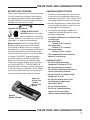
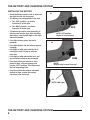
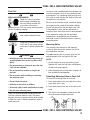
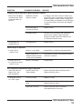
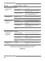
DANGER READ AND OBEY ALL SAFETY AND OPERATING INSTRUCTIONS BEFORE OPERATING TOOL. RAMSET GypFast (G2) OPERATOR’S SAFETY & OPERATING INSTRUCTION MANUAL GAS POWERED, LOW VELOCITY PISTON TYPE FASTENING TOOL TABLE OF CONTENTS / INTRODUCTION Introduction . . . . . . . . . . . . . . . . . . . . . . . . . . . . . . . . . . . . . . . . . . . . . . . . . . . . . . . . . . . . . . . . . . . . . . . . . . . . . . 2 An Overview of the GypFast (G2) Tool . . . . . . . . . . . . . . . . . . . . . . . . . . . . . . . . . . . . . . . . . . . . . . . . . . . . . . . . . 3 Safety Instructions . . . . . . . . . . . . . . . . . . . . . . . . . . . . . . . . . . . . . . . . . . . . . . . . . . . . . . . . . . . . . . . . . . . . . . . 4-6 Battery and Charging System . . . . . . . . . . . . . . . . . . . . . . . . . . . . . . . . . . . . . . . . . . . . . . . . . . . . . . . . . . . . . . 7-8 Fuel Cell and Metering Valve. . . . . . . . . . . . . . . . . . . . . . . . . . . . . . . . . . . . . . . . . . . . . . . . . . . . . . . . . . . . . . 9-10 Preparing and Use of the GypFast (G2) Tool . . . . . . . . . . . . . . . . . . . . . . . . . . . . . . . . . . . . . . . . . . . . . . . . . . . 11 Servicing. . . . . . . . . . . . . . . . . . . . . . . . . . . . . . . . . . . . . . . . . . . . . . . . . . . . . . . . . . . . . . . . . . . . . . . . . . . . . 12-13 Maintenance and Troubleshooting. . . . . . . . . . . . . . . . . . . . . . . . . . . . . . . . . . . . . . . . . . . . . . . . . . . . . . . . 14-16 Warranty. . . . . . . . . . . . . . . . . . . . . . . . . . . . . . . . . . . . . . . . . . . . . . . . . . . . . . . . . . . . . . . . . . . . . . . . . . . . . . . . 17 GypFast (G2) TOOL OPERATING MANUAL This manual is intended to acquaint you with Ramset’s GypFast (G2) tool. Unlike other power fastening tools, the GypFast (G2) tool is powered by an linear internal combustion motor. In simpler terms, your GypFast (G2) tool is powered by a motor similar to the one that powers an automobile. The tool ignites a fuel and air mixture to produce the energy to drive the motor, which in turn drives the fastener. As you will see, the GypFast (G2) tool is totally self-contained. It carries its own fuel supply and battery, along with a supply of fasteners. For ease of use, this manual is divided into sections (see Table of Contents). Each section of the manual is written with you, the tool operator, in mind. We have left out all of the technical terms so that you can readily understand how to get the maximum performance from your GypFast (G2) tool, and how to avoid damaging the tool or injuring yourself. But, to accomplish this, we need you to do two things: 1. READ THE MANUAL FROM COVER TO COVER BEFORE USING THE TOOL. 2. FOLLOW ALL INSTRUCTIONS IN THE MANUAL. The GypFast (G2) tool should be handled like other power fastening tools that you use. When used properly, it will meet your fastening needs. And, like most of your tools, when used improperly it can cause injury. If you are going to allow others to use the GypFast (G2) tool, it is your responsibility to make sure that they also read and comply with the instructions in this manual before attempting to operate the tool. Should you have questions about the GypFast (G2) system, or wish to obtain additional copies of this manual, please feel free to contact your Ramset Distributor Sales Representative. TABLE OF CONTENTS / INTRODUCTION 2 AN OVERVIEW OF THE GypFast (G2) TOOL DESCRIPTION SPECIFICATIONS The GypFast (G2) tool is a self-contained, fully portable tool that uses liquid hydrocarbon fuel to power a unique linear drive internal combustion motor. Dimension: In order for you to fully understand the information contained in this manual, you need a basic understanding of the tool. As you can see in the illustration below, the GypFast (G2) tool is made up of three assemblies: the Handle, the Motor, and the Magazine. As you examine the GypFast (G2) tool, become familiar with the three major assemblies and the various components located in each of them. The Handle Assembly contains the Fuel Cell, the Battery Voltage Indicator Light, Battery and the Trigger. The Motor Assembly contains the Cover and Filter, the Motor Housing, the Nose, and the Safety Yoke. The Magazine Assembly contains the Magazine, Magazine Dow and Hinge Pin. Height 16 inches Length 13 inches Weight: 7.9 pounds Cycle Rate: Intermittent Operation 2 to 3 pins per second. Continuous Operation 1000 pins per hour NOTE: Exceeding these rates could cause the tool to overheat, resulting in loss of performance or damage to tool components. By using the GypFast (G2) tool at its recommended operation rate you will be able to drive several thousand fasteners in a typical workday. Maximum Fastener Length: 2-1/2 inch x 0.140 dia. shank Magazine Capacity: 150 count coil. Battery: 6 volts D.C.—Provides enough energy to drive approximately 3000 fasteners on one charge. Fuel Cell: Liquid hydrocarbon—Provides enough fuel to drive up to 1000 fasteners. AN OVERVIEW OF THE GypFast (G2) TOOL 3 SAFETY INSTRUCTIONS The following safety instructions have been included in this manual to provide you with basic information necessary for safe operation of the GypFast (G2) Tool. DO NOT ATTEMPT TO OPERATE THIS TOOL UNTIL YOU READ AND UNDERSTAND ALL SAFETY PRECAUTIONS AND MANUAL INSTRUCTIONS. This tool must be operated only in a well-ventilated environment, because the tool exhausts carbon monoxide similar to a gas chain saw or lawnmower. Exposure to carbon monoxide may cause dizziness, nausea, or unconsciousness. Failure to follow all safety precautions and manual instructions can result in blindness, severe personal injury, damage to personal property, and damage to the tool. In addition to these instructions, additional training may be necessary, depending upon the type of fastening you wish to do. Contact your Ramset Distributor Representative for additional information. DANGER Do not attempt to operate this tool until you have read and understood all safety precautions and manual instructions. Failure to follow all safety precautions and instructions may result in a permanent loss of vision, serious personal or even fatal injury, property damage and/or tool damage. The GypFast (G2) Tool is an internal combustion device. It produces hot exhaust gases that may ignite flammable materials. This tool must not be used in a combustible environment or in the presence of combustible materials, such as flammable chemicals, adhesives, gasoline, or solvents. Do not expose the tool to temperatures in excess of 120°F (49°C). Fuel and/or the battery may burst, releasing flammable gas. SAFETY INSTRUCTIONS 4 ALWAYS keep the GypFast (G2) Tool, fuel cell, battery and battery charger out of the reach of children. 1. READ THIS MANUAL FROM COVER TO COVER. Always turn to this manual for information about the safe operation and servicing of the GypFast (G2) tool. If any portion seems unclear, or you have any questions, contact your Ramset Distributor Representative immediately. 2. WEAR EYE AND HEARING PROTECTION. Always wear hearing and eye protection devices when you are operating the GypFast (G2) tool or working in the vicinity of this tool. Also, your eye protection must meet the requirement of ANSI Standard Z87, and should have side shields for increased protection. 3. NEVER ASSUME THE TOOL IS EMPTY. Every time you pick up the GypFast (G2) tool, check the Magazine for fasteners. Never point the tool at anyone or yourself, even if you are absolutely sure there are no fasteners in the tool. The fastener you did not see is the fastener that can injure you or someone else. 4. NEVER ENGAGE IN “HORSEPLAY” WITH THE TOOL. The GypFast (G2) tool is not a toy. . . it is a power fastening tool. It is designed to drive a fastener through gypsum board or plywood sheets into steel studs. To accomplish this task, it generates a tremendous amount of energy. Fooling around, even when you are absolutely sure there are no fasteners in the tool, is asking for an accident. SAFETY INSTRUCTIONS 5. NEVER CARRY THE TOOL WITH YOUR FINGER ON, OR DEPRESSING, THE TRIGGER. You must remember that the GypFast (G2) tool operates in a specific sequence. The Safety Yoke acts as an operating feature that blocks the Trigger from completing the ignition circuit. Should you unintentionally depress the Safety Yoke while pulling the Trigger as you are carrying the tool... it could discharge a fastener. 6. NEVER OPERATE A TOOL THAT IS MALFUNCTIONING. If you determine that the GypFast (G2) tool is not working properly, and the problem is more than a simple fastener jam, stop using it immediately and refer to the Servicing Section of this manual. If the problem cannot be corrected with one of the steps covered in the Servicing Section, report the problem to your supervisor or Ramset Distributor representative. Do not attempt to make any additional repairs to the GypFast (G2) tool. 7. OPERATE THE TOOL ONLY ON THE WORK SURFACE. The GypFast (G2) tool should be operated only when it is in contact with the work surface. Always hold the tool firm and perpendicular against the surface to be fastened. 8. NEVER DISABLE OR REMOVE THE SAFETY YOKE. The GypFast (G2) tool is equipped with a device called the Safety Yoke. This device helps reduce the possibility of accidental operation by preventing the tool from operating until it is fully depressed on the work surface. The Safety Yoke must never be disabled or removed. Do not use the GypFast (G2) tool if the Safety Yoke is not working properly. 9. DO NOT LOAD FASTENERS WITH THE TRIGGER OR SAFETY YOKE DEPRESSED. When loading fasteners into the GypFast (G2) tool, you must avoid pulling the Trigger or while having the Safety Yoke depressed. When the tool is placed on a bench or other surface, the Safety Yoke might be depressed. When you are loading fasteners, you could accidentally pull the Trigger by grasping the Handle to steady the tool. These two actions will cause the GypFast (G2) tool to operate, discharging a fastener. 10. FASTENER REMOVAL OR CLEARING JAMS. With the GypFast (G2) tool pointed away from you and others, slightly push the Release Lever to open the Magazine door. Tip the tool Nose up slightly, and the fasteners will slide out. If you have a jammed fastener, or other problem with the operation of your GypFast (G2) tool, you should stop attempting to use the tool and refer immediately to the Servicing Section of the manual. 11. NEVER ATTEMPT TO OPERATE THE GypFast (G2) TOOL IF PARTS ARE LOOSE, DAMAGED, OR MISSING. Make sure all screws and nuts are properly tightened and all parts are properly installed and in good working order. If parts are missing, don’t attempt to make temporary repairs...contact your Sales Representative immediately. 12. NEVER DRIVE FASTENERS ON TOP OF OTHER FASTENERS OR TOO CLOSE TO OTHER FASTENERS. Fastening on top of or too close to other fasteners can cause the fastener to ricochet and cause serious injury. Fasten only in areas where the entire shank can penetrate. 13. NEVER FIRE INTO VERY HARD OR BRITTLE MATERIALS SUCH AS CAST IRON, TILE, GLASS, OR ROCK. These materials can shatter, causing sharp fragments and/or the fastener to fly freely. SAFETY INSTRUCTIONS 5 SAFETY INSTRUCTIONS 14. NEVER CARRY FASTENERS OR OTHER HARD OBJECTS IN THE SAME POCKET OR CONTAINER WITH FUEL CELL. The Fuel Cell could be punctured, causing serious injury. 15. NEVER ALLOW ANYONE TO USE THE GypFast (G2) TOOL UNLESS THEY READ AND UNDERSTAND THE TOOL MANUAL AND ALL SAFETY INSTRUCTIONS. It is the tool owner’s responsibility to make sure that all GypFast (G2) tool users read and fully understand all tool operation, safety and maintenance instructions. 16. FUEL CELL STORAGE. Fuel Cells contain flammable gases which are under pressure and must be stored in an area where they will not be exposed to an open flame, sparks, or temperatures above 120° Fahrenheit (49° Centigrade). Exposure to temperatures above 120°F (49°C) may cause the Fuel Cells to leak or burst, releasing the flammable gases and creating a risk of fire or explosion. SAFETY INSTRUCTIONS 6 17. FUEL CELL DISPOSAL. Never attempt to puncture, crush, burn or refill a Fuel Cell. Always dispose of empty cells with trash that will not be burned. Also, never place the Fuel Cell with other materials for reclamation or recycling. 18. TOOL STORAGE. At the end of every workday, remove the Battery and store it in the carrying case. Recharge the Battery only if required as indicated by a red charge light in the handle. 19. KEEP THE TOOL CLEAN. At the end of each work day, take a minute to wipe the GypFast (G2) tool with a clean rag. A dirty tool is more likely to jam or malfunction. 20. NEVER PLACE YOUR HAND OR FINGERS OVER THE NOSE OF THE TOOL. The fastener or piston can seriously injure your hand in the event of an accidental discharge. THE BATTERY AND CHARGING SYSTEM BATTERY AND CHARGER CHARGING INSTRUCTIONS The first step in preparing a new tool for operation is to fully charge the new Battery. New Batteries are shipped discharged and must be charged for 24 hours before first use. All subsequent charges will require at most a 3 hour charge. 1. Connect the round plug of the wall mount unit to the front of the charger base and plug the wall mount unit into any 120V AC outlet. A LED by the plug indicates the base unit has power. WARNING Important Charging Notes CHEMICAL/EXPLOSION HAZARD Read ALL instructions before charging or using battery. Failure to follow ALL instructions may result in fire, severe burns, or release of toxic materials. Battery Disposal: The EPA certified RBRCQ® Battery Recycling Seal on the nickel-cadium (Ni-Cd) battery indicates Ramset is voluntarily participating in an industry program to collect and recycle these batteries at the end of their useful life, when taken out of service in the United States or Canada. The RBRCQ® program provides a convenient alternative to placing used Ni-Cd batteries into the trash or the municipal waste stream, which may be illegal in your area. Please call 1-800-8-BATTERY™ (1-800-822-8837) for information on Ni-Cd battery recycling and disposal in your area. Ramset’s involvement in this program is part of our commitment to preserving our environment and conserving our natural resources. Holds both Ramset stick and New GypFast (G2) Battery 2. Set the charger base on a stable surface and insert the battery or batteries, contact first, into the opening of the charger base. 3. The GypFast (G2) charger incorporates a charge level indicator to inform the user of the battery charge level. A red light will illuminate at all times during a charge cycle. One green light = battery at 50% capacity Two green lights = battery at 75% capacity Three green lights = battery at FULL capacity The red light will not be lit when the battery is at full charge. CHARGING DONT’S • Do not charge battery when temperature is below 40°F (5°C). • Do not drop battery or charger. • Do not allow metal objects to come in contact with battery terminals. • Do not puncture or attempt to open battery case or cells. • Do not store battery where it will be subjected to temperatures above 120°F (49°C). • Do not incinerate battery. • Do not use a defective battery charger, one that overheats and/or smokes when plugged in. Ramset Battery Charger THE BATTERY AND CHARGING SYSTEM 7 THE BATTERY AND CHARGING SYSTEM INSTALLING THE BATTERY • Insert the battery into the tool as shown on the right with the clip facing out. #1 • The battery has two positions in the tool: 1. The “OFF” position—as shown in picture #1 to the right. 2. The “RUN” position—as shown in picture #2 to the right. OFF • To operate the tool be sure the battery is fully inserted into the tool. After installing the battery, note the LED light on the right side of the handle. • If the light flashes green, the tool is powered. NOTE: OFF position shown in small window #2 • If the light flashes red, the battery requires charging. • If the light is solid green and the fan is running, the tool is ready to take the next shot. • If the light is solid red and the fan is not on, the battery needs to be recharged. RUN • If the tool will not be used for a short period of time, click the battery back into the “OFF” position. This will prevent the tool from being fired. NOTE: Battery fully inserted into tool • If the tool will not be used for extended periods of time, remove the battery and store in the tool case. #3 NOTE: LED Light THE BATTERY AND CHARGING SYSTEM 8 FUEL CELL AND METERING VALVE Fuel Cell To eject the fuel, propellant pressure squeezes the inner fuel container, much as you squeeze a tube of toothpaste. This squeezing action ensures that all the fuel is used, and that the GypFast (G2) tool can operate in any position. DANGER EXPLOSION/FIRE HAZARD Read ALL safety instructions before using or handling the fuel cell. Failure to follow ALL instructions may result in explosion or fire. This may cause severe personal injuries or property damage. Because of this container-within-a-container design, you might hear the sound of fluid when shaking the fuel cell after all the fuel has been used. This is the propellant, which remains between the containers even after all the fuel has been expelled. Keep the fuel cell away from heat, sparks and open flame. Exposure to temperatures above 120°F (49°C) may cause the fuel cell to burst, releasing flammable gas. If you expose the empty fuel cell to extreme temperatures, the propellant gas will expand and could cause the container to burst, releasing flammable gases. Metering Valve The metering valve contains a fuel metering system to inject the correct amount of fuel into the combustion chamber. The red metering valve is the only valve that will operate properly with the GypFast (G2) tool. WARNING • Sunlight can raise the inside temperature of an unventilated truck or van to above 140°F (60°C). NOTE: • Do not puncture or attempt to open the fuel cell; it is non-refillable. 1. Do not attempt to reuse the metering valve! Replace with fresh fuel cell/valve, and dispose of spent cell/valve properly. • Do not incinerate, reclaim or recycle the fuel cell. 2. When replacing fuel cell also clean or replace air filter for optimum tool operation. • Do not smoke while installing or removing the metering valve. Attaching Metering Valve to Fuel Cell • Do not inhale the spray. 1. Press downward on the front side of the valve (stem side) until it seats. To attach the metering valve to a fuel cell: • Keep out of the reach of children. • Store fuel cell(s) in well-ventilated areas only. • Do not reuse metering valve. There is a second container inside the fuel cell. The inner container holds the fuel. The space between the inner container and the outer cylinder is filled with a gas, called the propellant, which is under pressure. 2. Press downward on the rear of the valve unit it seats. 3. The valve is now completely seated on the fuel can and can be inserted into the tool. FUEL CELL AND METERING VALVE 9 FUEL CELL AND METERING VALVE INSERTING FUEL CELL You complete the loading of Fuel Cell in the GypFast (G2) tool by closing the Actuator Cover. You do this by swinging it up and over the Fuel Valve/Cylinder Assembly and pushing down until the Actuator Cover snaps into position. With the Metering Valve Stem pointed toward the front of the tool, insert the Metering Valve/Fuel Cell Assembly. OUTDOOR WEATHER AND THE GypFast (G2) TOOL Use the GypFast (G2) tool outdoors, in clear weather, when the Tool, Fuel Cell, and Battery are between 20°F (-7°C) and 120°F (49°C). Colder temperatures may damage the GypFast (G2) Tool and Battery. Hotter temperatures may damage the Tool and Fuel Cell. Fuel should be stored out of direct sunlight in surroundings less than 120°F (49°C). After extended periods of continuous use, cool the Tool by running the Fan Motor. Operation when the Tool is less than 20°F (-7°C) may damage the tool. Fuel Cells at cold temperatures lose the required propellant force. Bring the Tool, Battery, and Fuel Cell above minimum operating temperature without direct exposure to flame, and check the Battery. As you slide the Metering Valve/Fuel Cell Assembly into the GypFast (G2) tool, you will notice that there is a Red Adaptor at the top of the Cylinder Pocket. As is shown in the illustration, this Adaptor is designed to ensure that the Metering Valve Stem is properly aligned with the small hole, or orifice that leads to the Combustion Chamber. Insert the Metering Valve Stem into the orifice of the red colored Adaptor. CAUTION The GypFast (G2) tool should not be used in the rain or where excessive moisture is present. These conditions may result in damage to tool components and cause tool to malfunction. FUEL CELL AND METERING VALVE 10 PREPARING AND USE OF GYPFAST (G2) TOOL FASTENERS The GypFast (G2) tool can drive only ITW Ramset fasteners. Any other fastener will cause tool damage and void your warranty. LOADING AND UNLOADING FASTENERS 1. Lay the tool on its right side, exposing the gate latch. 2. Unlatch and open the gate. Swing open the magazine cover. 3. Completely remove the blue tape from the coil and unwind 1-2” of nails. 4. Guide the first nail into the drive raceway while placing the coil of nails into the magazine. 5. Close the magazine and gate and you are now ready to start driving nails. To unload nails from a tool, first tear off excess collation sticking out the front of the tool. Unlatch and open the gate to remove the rest of the coil. GypFast (G2) TOOL OPERATION Proper technique assures smooth operation of the tool. Three easy steps to actuated the tool are: 1. ENGAGE THE TOOL PLACE GypFast (G2) ADJUSTABLE NOSEPIECE AGAINST WORK SURFACE. Then press down to close tool. Fan Motor will turn on, LED will be steady green. Fuel is injected into Combustion Chamber and mixed with air by the Fan. 2. SQUEEZE THE TRIGGER The Spark Plug sparks and fuel/air mixture ignites. Combustion powers the Piston Assembly, driving the fastener. 3. RELEASE TRIGGER - LIFT THE TOOL The Combustion Chamber opens. Fan exhausts hot gases and cools internal components. NOTE: If no additional cycles are made, fan will run for 7 seconds and then shut off. TO PREVENT UNINTENTIONAL TOOL OPERATION, AND POSSIBLE INJURY TO YOURSELF OR ANYONE IN THE WORKING AREA, BE SURE TO RELEASE THE TRIGGER AS SOON AS YOU HAVE FINISHED DRIVING FASTENERS. NEVER PRESS THE ADJUSTABLE NOSEPIECE AGAINST ANY OBJECT EXCEPT THE MATERIAL TO BE FASTENED. As the nails are being driven, the leftover collation is fed through the nose of the tool. As collation accumulates, it can be torn off by twisting and pulling down on the collation. Keep your finger off the trigger when performing this procedure. DEPTH ADJUSTMENT INCREASE DEPTH OF DRIVING FASTENER To increase the depth of fastener rotate the adjustment knob clockwise while holding the tool with the nosepiece facing away from your body. IF ROTATING THE ADJUSTMENT KNOB “CLOCKWISE BOTTOMS OUT (CAN’T BE TURNED ANY MORE) THE TOOL MAY NOT FIRE. BACKOFF DEPTH ADJUSTMENT BY ROTATING THE ADJUSTMENT KNOB TWO TURNS CLOUNTER-CLOCKWISE. DECREASE DEPTH OF DRIVING FASTENER To decrease the depth of fastener rotate the adjustment knob counterclockwise while holding the tool with the nosepiece facing away from your body. PREPARING AND USE OF GYPFAST (G2) TOOL 11 SERVICING Field service should be restricted to the following: q CHECKING THE ENERGY LEVEL OF THE BATTERY q RECHARGING THE BATTERY q CHECKING THE FUEL CELL AND METERING VALVE BATTERY CHECK Periodically check on the LED Battery Voltage Indicator Light—the LED in the Handle of the GypFast (G2) tool. When encountering a problem, the first step should always be to make sure the Battery has enough energy to operate the tool. q REPLACING THE FUEL CELL If the light is red, recharge the Battery, If the light is glowing green, indicating that the Battery is charged, check the ignition system. q CLEANING THE AIR FILTERS FUEL CELL CHECK q CLEARING A JAM Another typical service condition will occur when the Fuel Cell becomes empty. A typical symptom will be when the GypFast (G2) tool’s Fan operates and the LED is green, but the tool does not drive fasteners completely. In this case, take the Fuel Cell out of the tool, check to see if the Cell still contains fuel and that the Metering Valve is working. To determine is there is any fuel left in the Fuel Cell simply place the Metering Stem against a solid object, and gently push about three or four times. A small amount of fuel should be released each time. Never perform this test near an open flame or sparks, while smoking, or where the fuel may get into your eyes. If fuel is not released with each operation of the Metering Valve, there is no more fuel left in the cylinder and it must be replaced. Dispose of the empty Fuel Cell properly. Attempts to go beyond these procedures could result in serious personal injury or damage to the GypFast (G2) tool and voiding of the warranty. There are certain problems that you may encounter when you are using the GypFast (G2) tool that you will be able to correct on the work site. The following field service procedures are the only service procedures you should attempt. Anything else that may appear wrong with the GypFast (G2) tool should only be diagnosed and repaired by a fully trained service technician. If you have any reason to believe that your problem is beyond the service procedures in this manual, contact your Sales Representative immediately. DANGER Never attempt any maintenance of the GypFast (G2) tool without first removing the Fuel Cell and Battery. Maintenance should only be started after the tool is completely inoperative. AIR FILTER Open the cover by pressing slightly above the Red Adapter, and pivoting the cover open. The Air Filter simply lift out. Tap the filter GENTLY to remove any dust. You should check and clean the Air Filter every two days. SERVICING 12 SERVICING /MAINTENANCE CLEARING A JAM A typical problem you may encounter is having a jammed fastener. Because of the unique design of the GypFast (G2) tool, clearing a jammed fastener is easy. Damage to parts and/or excessive accumulation of dirt are principle causes of jams. If a jam should occur, proceed as follows: 1. Remove the battery and fuel cell. 2. Open the magazine, and remove all fasteners. Jammed fasteners should be clearly visible; check inside the nose for wedged fasteners and remove. 3. Clean the magazine, nose and all associated parts. 4. If the tool continues to jam, or you cannot clear a particularly difficult jam, have it serviced by an Authorized Ramset distributor. If you find that the tool’s Fan does not operate after clearing a jam: Check the condition of your Battery. If the Handle LED indicator emits a constant red glow when depressing the tool, recharge the Battery. MAINTENANCE COLD WEATHER OPERATING PRECAUTIONS Keep the tool in a warm area until you are ready to use it. If the tool is already cold, bring it into a warm area, and allow it to warm up before using it. DO NOT OPERATE THE TOOL WHEN IT IS COLD UNLESS FASTENERS ARE BEING DRIVEN INTO A WORKPIECE. EXTERNAL CLEANING The external parts may be cleaned as follows: 1. Remove the battery and fuel cell. 2. Open the magazine and remove all fasteners. 3. Remove all dirt and grit from the magazine and nose of the tool. 4. Clean the outside of the tool using a soft cloth and a mild degreasant like paraffin. CAUTION Never use highly volatile solvents such as gasoline to clean the tool. Do not allow any solvent to enter the interior of the tool. Solvents may cause O-rings to deteriorate, and possibly swell, causing a tool to malfunction, and creating a possible safety hazard. 5. Important: It is extremely important for safety reasons that all dirt and foreign materials be removed from around the safety yoke, and the safety yoke compression spring. The safety yoke must be free to move in and out without sticking or binding. The spring must positively return the safety yoke to its starting position whenever the safety yoke is released from being held in its position. EXTERNAL LUBRICATION Lubricate the areas where the adjustable nosepiece slides with General Electric Company “VERSILUBE” silicone lubricating grease G-322L or an equivalent. Do not use WD40. MALFUNCTIONS Be alert for tool problems. A malfunctioning tool must be immediately withdrawn from use and not used again until it has been repaired by a qualified service technician. Operating a tool which malfunctions is unsafe. Stop using the tool, and have it repaired. SERVICE AND REPAIR Except as specifically described in other sections of this manual, this tool must not be disassembled, serviced, repaired, or reassembled by anyone except qualified service personnel. Incorrect servicing, repairs and assembly of this tool may result in serious injury to the user and/or damage to the tool. Please contact your local Ramset sales person, or authorized Distributor for assistance and repair. SERVICING / MAINTENANCE 13 MAINTENANCE END-OF-WORKDAY ROUTINE At the end of each workday, conduct an end-ofworkday routine. These simple steps are based on maintaining the safety and operational efficiency of the GypFast (G2) tool. Before you leave the worksite: 1. Remove the Battery and store in the tool case. Always use the GypFast (G2) tool case for transporting and storing the tool. 2. Dispose of all empty Fuel Cells. Remember to dispose of these cells where they will not be found by children, crushed, punctured, or burned. 3. Place the Battery in its Charger only if it needs charging as indicated by the red charge light in the handle. 4. Wipe your GypFast (G2) tool with a clean, soft cloth. 5. Check Adjustable Nosepiece Element to ensure it is operating freely. These simple steps will not only ensure that your GypFast (G2) tool is ready to go to work the next day, but will also ensure that you get the maximum efficiency from your tool. MAINTENANCE 14 GypFast (G2) CORDLESS COIL TOOL ACCESSORIES A variety of accessories are available for the GypFast (G2) tool: •Battery • Clear Safety Glasses • GypFast (G2) tool Battery Charger • Magnetic Nosepieces for Lath Discs • Lath Disc (1” and 1-1/4”) Contact your ITW Ramset Distributor Sales Representative for additional information. TROUBLESHOOTING SYMPTOM POSSIBLE PROBLEMS SERVICE Preparing Tool for Operation—Battery/Charger Problems —Battery does not appear to accept charge. Green charger light does not come on. —Flashing lights on charger base unit. —Inoperative indicator lights on charger. —Try Battery in tool after 3 hours on charge cycle. If tool LED is green, charger lights are not working properly. Replace charger, monitor charging time to ensure Battery has adequate time for recharging. It’s normal for Battery to feel warm after properly charging. —Battery damaged or cycle life exhausted. —Replace Battery. —Damaged charger. —Discontinue use immediately and unplug from power source. Replace charger and tag or dispose of charger to prevent accidental reuse or connection to power source. —Damaged Battery —Replace Battery Normal Stage of Operation —Fan does not run —tool LED is off. —Battery is not charged. —Battery Terminals or Magazine battery contacts are oily, dirty, or corroded. —Fan does not run, or runs slower than normal —tool LED is red. —Battery is discharged. —Charge Battery according to Operating Manual. —Clean Battery terminals. Clean Magazine Battery terminals as required. —Charge Battery. Pre-Combustion/Combustion Stage of Operation —Safety Yoke does not depress fully—tool does not operate. —Head or Sleeve Steel Ring damaged. —Contact Authorized Ramset Distributor Sales Representative for service. —Tool will not cycle-fan runs, LED is green. —Fuel Cell is empty. —Replace Fuel Cell. —Spark Wire out of spark plug. —Contact Authorized Ramset Distributor Sales Representative for service. —Spark does not occur. —Contact Authorized Ramset Distributor Sales Representative for service. TROUBLESHOOTING 15 TROUBLESHOOTING SYMPTOM POSSIBLE PROBLEMS SERVICE Power/Exhaust Stage of Operation — Tool operates properly, but fasteners do not drive fully. — Tool operates, but no fastener is driven. — Tool operates erratically or appears to be losing power—tool LED is green. — Battery is discharged. — Charge Battery. — Fuel Cell is low. — Check Fuel Cell according to Operating Manual and replace as required. — There may be loss of seal in combustion chamber. — Press Safety Yokes against workpiece for one minute. Pull trigger. If fastener does not drive, there is a leak that requires service. — Fastener strip may be binding. — Use only fasteners meeting Ramset specifications. — Jammed fastener. — Clear jam according to Operating Manual. — Fuel Cell is low. — Check Fuel Cell according to Operating Manual. — Spark Plug wire is loose. — Contact Ramset Distributor SalesRepresentative for Service. — Filter element is dirty, causing tool to overheat. — Remove Filter element and clean according to Operating Manual. Use safe cleaning solution to remove stubborn debris. — Tool Sleeve or Steel Rings are dirty. — Clean tool per Cleaning Procedure. Returning/Purging Stage of Operation — Tool operated and drove fastener, but piston did not return to start position. — Built-up dirt and debris on Piston or in Nose bore. — Clean Piston and Nose bore with safety solvent. — Mushrooming of Piston Tip. — Contact Ramset Distributor Sales Representative for service. — Exhaust ports on the — Return tool to Authorized Ramset Distributor Sales Sleeve are dirty or clogged. Representative for service. — Tool (Sleeve) or Steel Rings — Contact Ramset Sales Representative for service are dirty. — Tool does not open — Tool is dirty. after tool cycles. — Clean tool or replace Work Contacting Element as required. If the GypFast (G2) tool will not operate after following the above service directions, return the tool to an Ramset Distributor Sales Representative for service. 800-241-5640 www.ramset.com TROUBLESHOOTING 16 WARRANTY RAMSET GAS TOOL SYSTEMS WARRANTY AND LIMITATIONS Ramset warrants that new GypFast (G2) systems power fastening tools, parts and accessories will be free from defects in material and workmanship for the period shown below. TWO-YEAR/50,000 SHOT WARRANTY A two-year/50,000 shot warranty, which ever comes first, will apply to all parts, except those listed below as normal wearing parts, or parts which are specifically covered by an extended warranty. SIX-MONTH/10,000 SHOT WARRANTY A six-month/10,000 shot warranty applies to the following parts, which are considered normal wearing parts: • Bumper • Piston Assembly • Steel Rings • Piston Rings The warranty period is based off of tool build date, determined from the tool serial number. Ramset may extend the warranty time frame from the date of purchase with a qualifying document proving date of purchase. WARRANTY STATEMENT Ramset’s sole liability hereunder will be to replace any part or accessory which proves to be defective within the specific time period. Any replacement part or accessory provided in accordance with this warranty will carry a warranty for the balance of the period of warranty applicable to the part it replaces. This warranty does not apply to part replacement required due to normal wear. This warranty is void as to any tool which has been subjected to misuse, abuse, accidental or intentional damage, use with fasteners, fuel, battery, or battery chargers not meeting Ramset specification, size, or quality, improperly maintained, repaired with other than genuine GypFast (G2) replacement parts, damaged in transit or handling, or which, in Ramset’s opinion, has been altered or repaired in a way that affects or detracts from the performance of the tool. Ramset MAKES NO WARRANTY, EXPRESSED OR IMPLIED, RELATING TO MERCHANTABILITY, FITNESS, OR OTHERWISE, EXCEPT AS STATED ABOVE and the liability AS STATED ABOVE AND AS ASSUMED ABOVE is in lieu of all other warranties arising out of, or in connection with, the use and performance of the tool, except to the extent otherwise provided by applicable law. Ramset SHALL IN NO EVENT BE LIABLE FOR ANY DIRECT, INDIRECT, OR CONSEQUENTIAL DAMAGES, INCLUDING, BUT NOT LIMITED TO DAMAGES WHICH MAY ARISE FROM LOSS OF ANTICIPATED PROFITS OR PRODUCTION, SPOILAGE OF MATERIALS, INCREASED COST OF OPERATION OR OTHERWISE. Ramset reserves the right to change specifications, equipment, or designs at any time without notice and without incurring obligation. WARRANTY 17 FOR TOOL REPAIR SERVICE CONTACT YOUR LOCAL AUTHORIZED RAMSET DISTRIBUTOR OR TO FIND YOUR NEAREST RAMSET TOOL REPAIR CENTER VISIT OUR WEB SITE AT WWW.RAMSET.COM OR CALL 800-241-5640 Concrete Fastening Systems Glendale Heights, IL 60139 800-RAMSET6 (1-800-726-7386) www.ramset.com Buy with Confidence... Buy From Your Authorized Distributor AN ILLINOIS TOOL WORKS COMPANY © ILLINOIS TOOL WORKS 2012 PRINTED IN THE U.S.A. Form No. GF (G2) GAS MANUAL-02/12