1
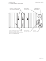
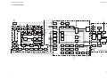
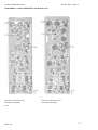
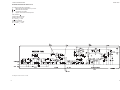
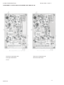
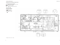
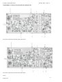
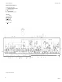
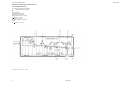
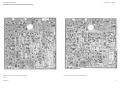
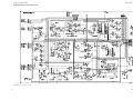
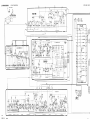
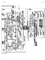
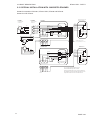
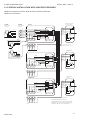
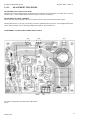
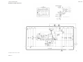
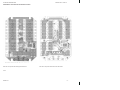
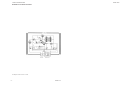
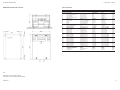
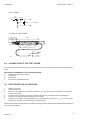
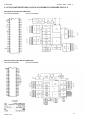
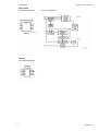
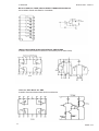
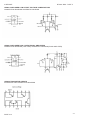
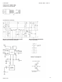
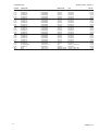
2 CIRCUIT DESCRIPTION
RT2047 DSC - PART II
2.16 N420 24V/12V REGULATOR
GENERAL DESCRIPTION
The regulator N420 is a general purpose 24V DC to 13.2V DC regulator, e.g. to be used for supply of VHF
radiotelephones.
The regulator N420 is a serial regulator with excellent noise performance.
2.16.1
TECHNICAL DATA
The regulator N420 is controlled from the connected VHF unit by the on/off button.
,QSXW9ROWDJH
21.6 to 31.2V DC
2XWSXW9ROWDJH
13.4V DC
2XWSXW&XUUHQW
Max. 8A DC
2SHUDWLRQ7HPSHUDWXUH5DQJH
15°C to +55°C
)XVH
8 Amp. 5 x 20 mm
&XUUHQWIURPRQRII7HUPLQDO
Less than 15 mA DC
2.16.2
PRINCIPLE OF OPERATION
N420 is a linear serial regulator where most of the loss is dissipated in resistors. It is provided with a
terminal for remote shut-down. If the on/off terminal is connected to the -terminal, the regulator is on. If
the on/off terminal is disconnected, the regulator is off.
2.16.3
CIRCUIT DESCRIPTION
The output voltage is regulated by the integrated voltage regulator IC1. The output voltage is 12V DC plus
the forward voltage over diodes D5 and D6: approx. 13.4V DC in total if T4 is conducting. If the output
voltage drops the current through IC1 and R5 increases. An increase in voltage across R5 will result in
an increase in current in T1 and the resistors R10 - R23 resulting in an increase in the output current.
T1 delivers most of the output current and FC1 only a small driver current.
If the input voltage is low and the output current is high, the voltage across R10 -R23 results in T1 going
into saturation. The voltage across R4 increases and when the voltage across R4 and VBE Of T1 is greater
than approx. 1 Volt, T3 starts to conduct base current to T1. This transistor then shunts the remaining
current to the output, bypassing R10 - R23.
When the input voltage and the output current are high, T1 is nearly saturated. When the input voltage
is low and the output current is high, the resistors R1 - R3 will result in saturation of both T1 and T2. The
combination of T1 in saturation and T2 delivering the remaining output current divides the total loss, so
the main loss is in the resistors giving low loss in the semi-conductors and a lower junction temperature,
resulting in a higher reliability for the whole regulator.
T4 is used to switch the regulator ON and OFF. If the ON/OFF input is disconnected T4 is OFF and the
base currents to T1 and T2 are zero and the current through IC1 will also be reduced to zero. The standby current consumption is then less than 10 micro amp. If the ON/OFF input is connected to - input, T4
goes into saturation and the regulator starts.
PAGE 2-42
9543