1
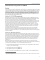
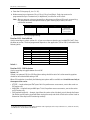
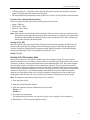
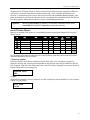
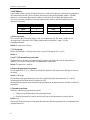
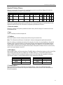
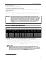
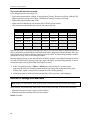
IVX 128 Plus: additional features
Installer’s programming supplement to IVX 128 documentation
Thank you for your purchase of IVX 128 Plus. In addition to what is covered in your IVX 128 Installation
Manual, this system has additional programmable features, described herein, as well as changes in
the way you program previously available functions; so please use this supplement with your
Installation Manual.
Function 15: System timing parameters
Function 153: Recall timers
What’s new: Separate settings for the hold and park recall timers.
Function 1531: Hold recall timer
This is the amount of time, in seconds, that a call will remain on hold before recalling to the extension
that initiated the hold.
Range: 5–960 seconds.
Default: 60 seconds.
Function 1532: Park recall timer
This is the amount of time, in seconds, that a call will remain on park before recalling to the extension
that initiated the park.
Range: 5–960 seconds.
Default: 60 seconds.
Function 16: System feature parameters
What’s new: Function 16 has been broadened: the recording alert has now become Function 161,
while connect tone and system-wide hold have been added.
Function 161: Recording alert tone
This sets whether the system plays a short beep every 15 seconds during a call recording, indicating to
both parties that a recording is in progress.
Default: Disabled (the beep does not play).
Function 162: Connect tone
This sets whether the system plays a system connect tone (the two short beeps a user hears when a
station answers).
Default: Enabled (the beeps play).
ESI (Estech Systems, Inc.) • 2601 Summit Ave., Plano, TX 75074 • 972 422-9700 • fax: 972 422-9705
e-mail: [email protected] • Web: www.esi-estech.com
0450-0201
Rev. E
IVX 128 Plus: additional features
Function 163: System-wide hold
Used in conjunction with station CO line key appearances. This function — when enabled — allows
station users to press the HOLD key to place a caller on hold so that any station programmed with CO
line key appearances can retrieve the call. After the user presses HOLD, the caller’s CO line will blink
green at the station placing the call on hold and red at all other stations. Any user who has a key
blinking due to this call can retrieve the call from hold by pressing the blinking key. (For stations
without line key appearances, placing a caller on hold puts him on exclusive hold only.)
Default: Disabled.
Function 21: CO line programming
What’s new: The capability to name CO lines; PRI programming.
1.
CO
2.
Name
3.
OUT
4.
Ring 1
Ring 3
Ring 5
Ring 9
1
CO line 1
9
X100
X100
X100
ID1
The steps are:
1. Choose the CO lines to program.
Note: If performing T1 programming (Function 2121), set trunk emulation as explained in the
Installation Manual before proceeding to step 2.
2. Name the CO line (optional — up to 10 alphanumeric characters).
To retain default values, press #. [See below for more details.]
3. Follow the remaining steps in the manual for the respective function, either Function 211 (analog
CO line programming) or Function 2121 (T1 CO line programming).]
Note: Function 213 (PRI programming) is detailed in this addendum.
Naming the CO lines (step 2, above)
During this step, you can name the CO lines you are programming. Each name can contain up to 10
alphanumeric characters. This step is optional. If you press # during this step, the default names (e.g.,
Line 1, Line 2, etc.) will be retained. If you select multiple CO lines to program, the name field will be
left blank; you can either press # at this point to keep all of the lines’ default names or, by entering a
name, assign the same name to all selected CO lines. If you want to change an already programmed
name to the default value, press HOLD to delete the name and then press # while the field is blank;
this restores the default values for all selected lines.
If used in conjunction with Caller ID, this feature causes the Caller ID name to appear on the top line,
and the CO line name on the bottom line, for five seconds after someone answers a call on that line.
After that, a call timer appears on the top line’s right side and, on the bottom line, the CO line name is
replaced by the usual lines-in-use display. If Caller ID is not enabled, the CO name will appear on the
top line of the display and the CO line use indications will be on the bottom line.
Default: Line numbers.
2
IVX 128 Plus: additional features
Special information: Using the DLC12 for ISDN PRI1
Overview
The DLC12 card, one of the five available port cards for IVX 128, is a plug-in design that can be installed
in any of the seven available card slots on the system highway. Each card provides either a T1 interface
supporting 24 DS0 channels and 12 digital stations or an ISDN PRI interface supporting 23 B (bearer)
channels, one D (datalink) channel and 12 digital stations. A jumper (labeled JP6) on the DLC12 card
must be plugged onto pins 5 and 6 of JP6 to enable ISDN PRI functions. For more information on the
DLC12 card, refer to the IVX 128 Installation Manual (ESI part #0450-0074) and the Digital Line Card
Configuration Instructions (ESI part #0450-0296).
Function 213: DLC12 (PRI) programming
The options under Function 213 are used to configure the DLC12 card for an ISDN PRI line with 23 B
channels and one data channel (24). The first line of the display will indicate the card number and the
type of card. The frame format and line coding will default to the ISDN standard of ESF/B8ZS.
One of the main features of PRI is dynamic channel allocation, meaning all telephone numbers on the
PRI span can come in over any of the 23 channels. This eliminates the need to forecast call volume for
the main published number, because as few as one channel or as many as 23 channels can be
occupied at any time by callers to the main published number. For example, channels 1–20 can be
occupied by callers to the main published number while channels 21–23 are open or occupied with
DID callers; later, channels 1–15 can be occupied by DID callers while channels 16–23 are open or
occupied by callers to the main number.
The components required for programming are CO line programming (Function 2131) and Switch
protocol (Function 2134). In addition to the required fields, there are also fields for line build-out
(Function 2132), CSU emulation (Function 2133) and DID enable/disable (Function 2135) that typically
are left out at default.
Function 2131: PRI CO line programming
The 23 voice channels support both inbound and outbound traffic. Answer ring assignments must be
assigned for daytime and night routing. This routing will be followed only if DID is disabled. Because of
the dynamic channel allocation on PRI, there is no control over the channel any given number rings in
on. For this reason it is recommended that all channels be routed the same. For maximum flexibility,
we allow each channel to be selected individually. For example: in some cases, the outbound line
group needs to be different or possibly have the first five channels be live-answer, then send the
overflow to ID 1.
When performing the CO line programming, remember that there are only 23 channels; the 24th
channel is used for signaling, so it does not take up a port and it needs no programming. If the PRI card
is in the first slot, the COs will be 1–23 and the next card will start with CO 24.
1. Using the programmable feature keys, select the line keys to be programmed (use the scroll keys
for lines 17–23). Press # to confirm.
2. Select Dialtone transmit on or off. Default: Off.
3. Select Playback transmit on or off. Default: Off.
4. Enter CO name (see “Entering alphanumeric characters” on page C.2 in the Installation Manual).
1
On IVX 128, the DLC12 must be configured for T1. IVX 128 will not support a DLC12 configured for PRI. Only IVX 128 Plus will
support a DLC12 configured for PRI.
3
IVX 128 Plus: additional features
5. Enter the CO line group (9, 8 or 71–76).
6. Make answer ring assignments: Ring 1, Ring 3, Ring 5 and Ring 9. Each ring count can be
programmed for up to 10 extensions, a department, a mailbox or an ID branch.
Note: After you program a ring assignment for a department, mailbox or ID branch, no remaining
ring assignments will be required because, upon reaching any of these, the call is
considered answered.
Example:
Ring 1
Ring 3
Ring 5
X100
X100, X101, X102
ID1
Ring 9
Not used*
(system won’t prompt
you to program)
7. Repeat steps 1–6 for night programming.
Function 2132: Line build-out
Use the arrow keys to select a value of 1–8 (you can make one selection per installed PRI Card2). Press
the # key to confirm. The level programmed depends on the application (CSU or DSX-1) indicated in the
following table:
Level
1
2
3
4
5
6
7
8
CSU line build-out
0 dB
N/A
N/A
N/A
N/A
-7.5 dB
-15 dB
-22.5 dB
DSX-1 line build-out
0 to 133 feet
133 to 266 feet
266 to 399 feet
399 to 533 feet
533 to 655 feet
N/A
N/A
N/A
Default: 1.
Function 2133: CSU Emulation
Use the arrow key to toggle between On and Off.
Default: Off.
If there is no external CSU, the CSU Emulation setting should be set to On but the remaining options
should be left at the default setting of Off.
When CSU emulation is enabled, the following test options will be available and should be used only at
the request of the carrier:
• ATT PRF — Loopback test per AT&T spec 62411 for performance assessments, sent to the carrier on
ESF trunks only.
• ANSI PRM — Loopback test per ANSI spec T1.403 for performance assessments, sent to the carrier
on ESF trunks only.
• PLB (payload loopback) — Accepts signal from the carrier at the chip level, puts it through the framer
(de-frames and re-frames signal with data staying the same) and sends it back to the carrier. Used to
determine if the chip itself is functioning correctly.
2
4
In any IVX 128 Plus system, you may install a maximum of two digital port cards in any combination: i.e., either two T1 Cards,
two PRI Cards or one T1 Card and one PRI Card.
IVX 128 Plus: additional features
• LLB (line Loopback) — Sends the signal back right at the point it enters the chip before it hits the
framer. This helps determine if the line itself is good.
• NET LLB (network loopback) lets the carrier put the DLC 12 card’s CSU into any of the loopback modes.
Function 2134: Switch protocol selection
Use the scroll keys to select from the four switch options for your carrier.
• Nortel – DMS100
• AT&T/Lucent – 5ESS
• National – NI2 - Default
• Siemens - EWSD
Note: Most switches can emulate the various protocols. Please be sure to base your selection on the
protocol being used rather than the actual switch manufacturer. For example, your central office
could have a Nortel DMS 100 switch but have the span configured as NI2; in this instance, you
would select the option for National/NI2.
Function 2135: DID
With DID enabled, call processing will check first the pilot number table and then the DID table, and
route the call accordingly. Any number not found in the pilot number or DID tables (programmed in
Function 224) will be routed to the DID exception routing. With DID disabled, all calls will follow the
routing as programmed in PRI CO line programming (Function 2131).
Default: Disabled.
Function 225: Pilot number table
Every call on a PRI span is sent with the called number in the setup message. This means you can
determine whether to use a number as a pilot number or as a DID number. Pilot numbers are a means
of routing a company’s primary published phone number differently from a DID. The system supports
up to five pilot numbers, each with its own answer ring assignment. This is important, because the
dynamic channel allocation prevents you from routing based on channel. Pilot numbers can be routed
to an ID branch, department, extension or mailbox. This varies from DIDs in that, when a DID number is
routed to an extension, it is considered answered and follows the busy/no-answer routing of the
extension; but, with pilot numbers, the call will be routed to the extensions for live answer for the
designated number of rings, then can be routed to an ID branch in the event of busy/no-answer.
Note: This feature is accessible only if Function 2135 is enabled.
1. Enter the pilot number.
2. Enter the name for the pilot number.
3. Enter the maximum channels allowed for this pilot number.
Range: 1–23.
Default: 23.
4. Set answer ring assignments.
(For programming information, see step 6 in Function 2131, on page 3 of this document.)
5. Repeat steps 1–4 for the remaining pilot numbers.
5
IVX 128 Plus: additional features
Function 234: PRI receive volume
Many variables can affect the volume of PRI lines. Different volume levels may be required when
connecting a PRI port card depending on the signal level of the PRI line. The volume level can be
adjusted by increasing or decreasing the setting in this function. By default, the setting is –6 dB;
changes to the setting are in 2-dB increments.
Example: If calls received at the extension have low volume levels, the pad level for that PRI circuit
can be adjusted to increase the volume. Select the circuit to adjust by pressing the
appropriate DSS key and press # to confirm. Use the scroll keys to select the appropriate
dB level and press # to confirm.
Programming a circuit
To program a circuit, select the appropriate DSS key and press the # key to confirm. You can select from
the first set of 16 COs, and then press the scroll keys to select the from the remaining 7 CO lines on the
first PRI port card. Scrolling again will allow you to select the 16 COs on a second PRI port card if one is
installed, and scrolling again will allow you to select from the 7 remaining COs. If there is only one PRI
port card installed, then scrolling will return you to the first 16 COs.
PC3 PRI 13-36
CO22 CIRCUIT 10>
After selecting the COs to program, use the scroll keys to select the new level of gain or loss in dB.
Press # to confirm. Select additional circuits to adjust and program as above.
RECEIVE VOLUME
LINE COMP -28DB>
Range: -28 dB to 6 dB (lowest to highest gain, respectively).
Default: -6 dB.
Function 31: Extension definition and routing
What’s new: Page zones 4–9; support for local IP Feature Phones and Remote IP Feature Phones.
Page zone setting
In Step 7 (extension page zones assignment), you can enter a page zone from 1 through 9. Default: 0.
Support for IP phones
With the installation of a Local Network Card, IVX 128 Plus will support up to 12 local IP Feature
Phones. With a Remote Network Card and Local Network Card, IVX 128 Plus can support a combination
of up to 12 local IP Feature Phones and Remote IP Feature Phones. Complete the new Function 8
programming (see page 15 in this document) before programming local or Remote IP Feature Phones.
6
IVX 128 Plus: additional features
Programming for IP Feature Phones is similar to that for Digital Feature Phones, except that additional
information is required. If the extension entered during step 1 is for a Digital or Analog extension,
Function 31 programming is the same as described in the IVX 128 Installation Manual; however, if the
extension entered is one of the 12 extension numbers assigned to the Local Network Card, the IVX 128
Plus will prompt for additional information as shown in the following procedures.
Important:
Where any gray shading (■) appears in an example, it represents values either
unavailable to the function or unused in the particular example.
Local IP Feature Phones
Below is an example of the portion of a completed programming worksheet (Appendix II) for local IP
Feature Phones.
Ext
Type
MAC
Name
CO
CF day
112
Local IP
113
Local IP
114
Local IP
115
Local IP
116
Local IP
00304D144F5C
Sam
9,8
117
Local IP
00304D144F5E
George
9,8
CF
night
Pg zone
00304D13579A
Jane
9
00304D135664
Roger
9
MB109
X105
0,1,2
MB110
MB110
0, 2
00304D1357FF
Sally
9,8
MB111
MB111
0, 2
00304D144F5B
Dean
9,8
MB112
MB112
0, 2
MB113
MB113
0,1,2
MB114
MB114
0, 2
Ext
Prior to programming extension definition for a Local IP Phone, install the phone on the IVX 128 Plus
network and power on the Local Phone.
1. Extension number
Extension numbers for IP phones, whether remote or local, will in be in a contiguous range of 12
extension numbers with a starting point dependent on the position of the LNC card within the IVX 128
Plus. Example: If the LNC is the second port card in the IVX 128 Plus, the extensions reserved for the IP
feature Phones will be 112 through 123.
STATION PROG
EXT:_
2. Type
If the extension entered is for an IP extension, use the scroll keys to choose whether it is to be a remote
station or a local station.
X123 TYPE
LOCAL
7
IVX 128 Plus: additional features
3. MAC Address
Enter the MAC address for the IP Feature Phone to be used at this extension. If the phone is powered on
and connected to the IVX 128 Plus network, the phone LCD will display the MAC address. The MAC
address is a 12-character alphanumeric address, of which the first six digits will always match
(00 30 4D). Enter the complete 12-character alphanumeric address. Use the following keys to enter
alphabetic characters:
Press...
To produce...
Press...
To produce...
PROG/HELP
A
RELEASE
D
REDIAL
B
FLASH
E
CONF
C
TRANSFER
F
4. Extension name
This is used for the LCD display, reports, and as a programming aid. The name’s length can be
no longer than 10 characters (see “Entering alphanumeric characters,” page C.2 in the
Installation Manual).
Default: The extension number.
5. CO line group
Assigns the extension’s ability to access one or more CO line groups (9, 8, and 7).
Default: 9.
6. and 7. Call forward busy/no answer
The extension can be set to call forward busy/no answer to another extension (or department), a
mailbox, or a branch ID for day mode, and differently for night mode.
Default: The extension’s mailbox.
8. Extension page zone assignment
List the page zones (1, 2, 3...) that are to include this extension. All stations are in All Page and cannot
be edited.
Default: 0 (All page).
The overhead paging port (extension 199) can be paged along with other extensions in a zone by
including the desired page zone(s) for extension 199.
All digital phone extensions are included in the all-page zone. Analog extensions cannot be included in
page zones.
9. Operator translation
Extension 0 (Operator) programming requires:
• Programming call forwarding for day and night mode
• Entering the extension number to which calls are to be directed when someone dials 0.
Default: 100.
The Local IP Phone will become active when the extension definition programming is completed for the
assigned extension.
8
IVX 128 Plus: additional features
Remote IP Feature Phones
Below is an example of the portion of a completed programming worksheet (Appendix II with the
Installation Manual) for remote IP Feature Phones.
1.
2.
3.
4.
6.
5.
7.
Remote-access
IP address
8.
9.
10.
11.
12.
13.
CO
CF
night
Pg
zone
Ext
Name
CF
day
9
Ext
Type
IP address
MAC
Gateway IP
UDP
port
118
Remote
IP
192.168.1.3
00304D135661
192.168.1.1
59118
221.46.197.104
Roger
119
Remote
IP
192.168.210.5
00304D135F2F
192.168.210.1
59119
221.46.197.104
Sally
MB118 MB118
9,8 MB119 MB119
Before entering programming extension definition for a Remote IP Phone, connect the phone to the
network on which the IVX 128 Plus resides and power-up the Remote IP Phone.
1. Extension number
Extension numbers for IP phones, whether remote or local, from the range of 12 extensions for the
Local Network Card.
2. Type
Use the scroll keys to select and press #.
3. IP address
Enter the IP address that the remote phone will be using at its remote site.
Note: This information will have to be obtained in advance of programming the remote phone.
Enter this address in dotted-quad notation (for example, 192.168.1.3) using the # key as the period
between octets. The phone must be on the same subnet as the LAN interface of the gateway device
(cable modem, router, etc). For instance, if the LAN interface’s IP address is 192.168.210.1, and its
subnet mask is 255.255.255.128, the first three octets of the phone’s address must be 192.168.210,
and its last octet between 2 and 127.
4. MAC address
Enter the MAC address of the remote phone. The MAC address of the phone appears on the second line
of the display when the phone is powered up. The MAC address is a 12-character alphanumeric
address, of which the first six digits will always match (00 30 4D). Enter the complete 12-character
alphanumeric address. Use the following keys to enter alphabetic characters:
Press...
To produce...
Press...
To produce...
PROG/HELP
A
RELEASE
D
REDIAL
B
FLASH
E
CONF
C
TRANSFER
F
5. Gateway address
Enter the IP address of the remote phone’s default gateway – that is, the LAN interface of the
gateway device at the remote site. The phone must be on the same subnet as the LAN interface of
the remote gateway.
9
IVX 128 Plus: additional features
6. UDP port
Enter the first two digits of the remote phone’s UDP port. This number is the base UDP port. The default
UDP base is 59. The last three digits will be the station’s extension number, and will be populated by
default. Extension 112, for example would have a UDP port of 59112 by default.
The UDP port for the remote phone does not have to be the same as for the IP PBX (as programmed in
Function 81). The UDP port for the remote phone must be one that the remote WAN gateway can
program as “open” and must not be already assigned to another device at the remote site. The remote
gateway will then have to be programmed to recognize that traffic destined for that UDP port should be
allowed to pass through its security system.
If the remote gateway cannot open UDP port 59xxx (where xxx is the phone’s extension), or if that port
is already open but designated for another device, the installer can choose any other base UDP number
between 10 and 65, inclusive. After entering the first two digits, the phone’s extension will populate
the last three digits.
7. Remote-access IP address
Enter the IP address that will be used for remote access to IVX 128 Plus. The display will default to the
IP address entered in Function 82 (see page 16). If a Remote IP Feature Phone will use this address to
connect to IVX 128 Plus, press # to confirm; if a Remote IP Feature Phone will use an alternate IP
address to connect to IVX 128 Plus, enter that address and press # to confirm. “SAVE PARAMETERS?”
will appear on the display. If you have correctly entered the IP addressing parameters (items 1–7),
press # to program the parameters for any Remote IP Feature Phone; to abort programming, press * to
restore the system parameters to their previously set values.
8. Extension name
This is used for the LCD display, reports, and as a programming aid. The name’s length can be no
longer than 10 characters (See “Entering alphanumeric characters” in the Installation Manual).
Default: The extension number.
9. CO line group
Assigns the extension’s ability to access one or more CO line groups (9, 8, and 71–76).
Default: 9.
10. and 11. Call forward busy/no answer
The extension can be set to call forward busy/no answer to another extension (or department), a
mailbox or a branch ID for day mode and differently for night mode.
Default: The extension’s mailbox.
12. Extension page zone assignment
Remote IP phones cannot participate in any page zones.
10
IVX 128 Plus: additional features
13. Operator translation
Extension 0 (Operator) programming requires:
• Programming call forwarding for day and night mode
• Entering the extension number, department, mailbox or branch ID to which calls are to be directed
when someone dials 0.
Default: 100.
The Remote Phone will become active, in a local mode, when extension definition programming is
complete for the assigned extension. The Remote Phone is ready for installation at the remote site.
Important: If the Remote IP Feature Phone is not connected to the IVX 128 Plus network at the
time of extension definition programming, critical addressing parameters will not have
been programmed into the Remote Phone. Connect the Remote Phone to the network
and repeat Function 31 extension programming for this extension, pressing # at the
appropriate times to confirm previously entered values. (Performing this step again
causes the IVX 128 Plus to send the programming information to the Remote IP
Feature Phone.)
Function 32: Extension feature authorization
What’s new: Two features, auto-page and external forwarding (including forwarding to toll numbers).
1.
Ext.
2.
Name
XXX
100
101
102
110*
Default
Jane
Roger
Sally
Bill
3.
Call
wait
Y
Y
Y
Y
Y
4.
DND
Y
Y
Y
Y
5.
AA
block
N
N
N
N
N
6.
Rec.
Y
Y
Y
N
7.
Svc.
obs.
N
N
N
N
8.
Toll
allow
Y
Y
Y
Y
Y
9.
Sys.
spd. dial
Y
Y
Y
Y
Y
10.
Auto
page
N
Y
N
Y
N
11.
Ext.
fwdg.
N
N
N
N
N
12.
Fwdg. to
toll nos.
N
N
N
N
N
10. Auto-page — Lets the user turn auto-page (defined below) on or off at his/her station.
Note: This feature is used in conjunction with the directory names recorded in Function 62 and is
not active until a directory name is recorded for the extension.
If the station user has his/her mailbox set to answer with personal greeting 3 and a caller presses 3
to page that user, this feature automatically pages the station user in the page zones entered in
Function 31. If no page zone is entered, all IVX Digital Feature Phones on the system are paged.
Default: Disabled.
Note: When auto-page is enabled, IVX 128 Plus will use the last installed idle digital port to
perform the page. Therefore, if a phone is on the last installed port (e.g., X111 on a system
with only a 612 Card), the phone’s user may experience a brief delay in telephone operation
if he/she picks up the handset (or presses SPEAKER) during the auto-page.
* An example of an analog phone.
11
IVX 128 Plus: additional features
11. External forwarding — Allows the station user to enable the off-premises-“reach-me” feature (the
user can give, to callers who are forwarded to his/her voice mailbox, the option of trying to reach
him/her at another number). This requires a trunk-to-trunk transfer and will use two CO lines for the
length of the conversation. The user must set his/her mailbox to answer with personal greeting 2
and inform the caller to press 4 for this option.
Default: Disabled.
Note: After the system dials the last digit of the external forwarding number, it will begin to play a
prompt saying, “You are receiving a forwarded call. Press any key to accept.” This prompt will
play continuously for 30 seconds. When DTMF is detected at the remote end, both trunks are
connected. If no DTMF is detected, the caller is forwarded to the user’s voice mail. While the
two trunks are connected, the system constantly monitors the lines for open loops. If it
detects an open loop on either line, it terminates both CO connections. Additionally, the
system periodically will monitor for voice on the connected COs. If it detects no voice traffic,
it terminates both CO connections. Finally, if both COs are connected for a programmable
period (default is 60 minutes), the system will terminate the connection, regardless of the
presence or absence of activity.
12. Forwarding to toll numbers — This feature is used in conjunction with external forwarding (see
previous item). When enabled, this feature lets the user program a long-distance number for
external forwarding.
Default: Disabled.
Function 41: Auto attendant branch programming
What’s new: Now, when creating an outdial branch, you can choose trunk-to-trunk for the outdial
method; therefore, Centrex is no longer required for outdialing.
GoTo Branch
GoTo Outdial
When you select a GoTo Outdial branch to program, the system will prompt you to select the outdial
method — either trunk-to-trunk or Centrex. If you select Centrex, you’ll program the system as always
(i.e., nothing is different from the Installation Manual.) However, if you select trunk-to-trunk:
1. The system will access another CO line to call the outdial number.
Note: Two CO lines will be utilized, one for the inbound call and one to call the outdial number.
3
2. After the outdial number (including the access code and any special characters ) is entered, the
system will prompt you to indicate whether DTMF detection at the remote end is required before
completing the connection.
If DTMF detection is not required, the system will complete the trunk-to-trunk connection after
dialing the final digit of the outdial number (blind transfer); ignore steps 3–4.
However, if DTMF detection is required, continue with these steps.
3. The system will begin to play the following prompt after the final digit of the outdial number:
“You are receiving a forwarded call. Press any key to accept.” This prompt will play continuously for
30 seconds.
3
Special characters — such as P for pause or F for flash — can also be entered in the dial string.
12
IVX 128 Plus: additional features
4. What happens now depends upon whether the system detects DTMF from the called party:
• If it does, the system completes the trunk-to-trunk connection.
• If it doesn’t, the system forwards the call to the programmed call forwarding for this outdial
branch (the next step for which you’re prompted if DTMF detection is required).
Note: You’ll be prompted to enter a call forwarding destination for an outdial branch only if
(a.) the branch uses trunk-to-trunk and (b.) DTMF detection is required.
Enter an extension, branch ID or mailbox number for the day/night call forwarding of
this GoTo Outdial branch.
Note: While both COs are connected, the system constantly monitors the lines for open loops. If it
detects an open loop on either line, it terminates both CO connections. Additionally, the
system periodically will monitor for voice on the connected COs. If it detects no voice traffic,
it terminates both CO connections. Finally, if both COs are connected for a period
(programmable; default is 60 minutes), the system will terminate the connection, regardless
of the presence or absence of activity.
Function 43: Automatic day/night mode table
What’s new: A second day mode and a second night mode.
The ability to re-record ID1 remotely.
You program the day/night mode table by selecting the day of the week, then entering the start time,
and then selecting the mode — day, night, day2 or night2. At the time you’ve programmed, the
appropriate greeting for that mode will play and the system will follow the appropriate day or night
forwarding. Day forwarding is the same for both day mode and day2 mode; night forwarding is the
same for both night mode and night2 mode. Enter the times in military time (0000–2359). Each day
can have up to six different times.
1. Select the day of the week by pressing a scroll (▼ or ▲) key.
2. Press # to confirm.
3. Enter the day’s start time in 24-hour format.
4. Press # to confirm.
5. Select the mode — day, night, day2 or night2 — by pressing a scroll (▼ or ▲) key.
6. Press # to confirm.
7. Repeat steps 3–6 for the day’s next setting or press # again to program another day.
8. When finished, press # again to exit.
Note: To delete an entry, press HOLD.
13
IVX 128 Plus: additional features
Day/night mode worksheet example
In the example below, the company has:
• Day mode programmed for: 8 AM to 12 noon Monday, Tuesday, Thursday and Friday; 8 AM to 2 PM
Wednesday and Saturday; and 1 PM to 5 PM Monday, Tuesday, Thursday, and Friday.
• Night mode programmed for after 5 PM.
• Night2 mode for Wednesday and Saturday after 2 PM and all day Sunday.
• Day2 mode for lunchtime Monday, Tuesday, Thursday and Friday.
Mon.
Tue.
Wed.
Thu.
Fri.
Sat.
0800 D
0800 D
0800 D
0800 D
0800 D
0800 D
1200 D2
1200 D2
1400 N2
1200 D2
1200 D2
1400 N2
1300 D
1300 D
1300 D
1300 D
1700 N
1700 N
1700 N
1700 N
Sun.
Normally, the system’s day/night mode operation will be manually controlled at a Digital Feature Phone
and/or set to follow automatically the day/night mode tables (programmed by the Installer). Also, the
Administrator can remotely change the mode and/or re-record ID1 and the holiday greeting to handle
unexpected closings, such as for inclement weather.
Remotely logging into the system with either the Installer password or the Administrator password lets
the caller re-record the ID1 greetings (day, night, day2 and night2) and the holiday greeting, as well as
change the mode to day/night/holiday/day2/night2 (or auto).
1. At the main greeting, enter **789# or **456# (or the new password) — to enter remote
programming mode. You’ll hear prompts that will let you change the answer mode (day, night,
holiday, day2, night2 or auto) and/or re-record ID1 or the holiday greeting.
2. Follow the prompts to perform the desired operation. Exit by pressing * and hanging up.
Function 58: Message move and delete
What’s new: This new function, when enabled, adds a convenience feature to moving messages.
When enabled, this prompts the mailbox user, when moving a message, to do one of the following:
• Move the message and save a copy in his/her mailbox.
• Move the message and delete it from his/her mailbox.
Default: Disabled.
14
IVX 128 Plus: additional features
Function 8: IP PBX Programming
What’s new: IP addressing capability to add Local IP Feature Phones, Remote IP Feature Phones and
PC Phone; Esi-Link capability to connect up to 100 ESI IP PBXs.
With the installation of a Local Network Card, IVX 128 Plus becomes an IP PBX, thus gaining the
capability to support ESI local IP Phones. Also, an IVX 128 Plus system equipped with a Local Network
Card and a Remote Network Card can support local IP Phones and Remote IP Phones. Function 8 is
used to program the IP addressing information for IVX 128 Plus to operate over a local LAN and a WAN
or Public Internet. Refer to Function 31 for programming of the Remote and Local IP extensions.
Note: Neither IVX 128 Plus nor the IP phones use any subnet masking; that is, their subnet mask is
0.0.0.0. In other words, the cabinet and the phones will communicate with any other device on
their Ethernet segment, as long as that device has an IP address.
The IP addressing capabilities also allow IVX 128 Plus to use Esi-Link technology to connect as many as
100 ESI IP PBXs (any combination of IP 200, IP 40 or LNC- and RNC-equipped IVX 128 Plus systems)
into a single phone network via the public Internet and private WANs. When you enter F8, the first
screen will appear as shown below. Press 1 to manage licenses, 2 to program the local cabinet, and 3 to
program multisite (Esi-Link) settings.
IP PROGRAMMING
CMD:_
Function 81: License management
Function 81 is an Installer function, used to add and delete licenses and display license information.
When an end user needs more licenses for local, remote or soft phones, VIP software, or Esi-Link
software, the reseller will purchase them from ESI.
LICENSE MGMT
1=UPDATE 2=VIEW
Function 811: Update licenses
When the purchase order for new licenses is approved, the reseller will contact ESI to receive an
alphanumeric code to enter into the user’s IVX 128 Plus. This code will enable the extra licenses when
IVX 128 Plus is rebooted.
UPDATE LICENSES
_
The same procedure will be used in the unusual event that a user wants to delete licenses, for whatever
reason. The financial arrangements for such an occurrence will be strictly between the user and the reseller.
Function 812: View licenses
This function is used to view the number of licenses in each category. Press the scroll key to move
through the license types. Press # to exit.
LICENSE ESI-LINK
MAX:96 USED:3
LICENSE PC PHONE
MAX:0 USED:0
LICENSE VIP
MAX:0 USED:0
15
IVX 128 Plus: additional features
Function 82: Local IP PBX programming
Function 82 is an Administrator-level function used to program the local IP PBX so that it can
communicate with the phones on its own network segment (“local phones”), with Remote IP Feature
Phones, and with other IP PBXs. The administrator will be able to:
• Assign IP addresses and UDP ports to the IP PBX and the local IP phones
• Set limits to the number of available remote talk paths
• Set up the pool of IP addresses used by local IP phones
Function 821: Program IP PBX addresses
Assign IP address to the IP PBX
The administrator assigns an IP address to the IP PBX, using four-octet (dotted-quad) notation. The
default is 192.168.248.1. Press # for the periods between the octets. Press # again when finished.
PBX PRIVATE IP
192.168.248.1
Normally, the IP PBXs will use private IP subnetworks (as defined in RFC 1597*) rather than
public subnetworks. For simplicity’s sake, it is a good idea to keep all the IP PBX’s components within
the same address range. If the administrator chooses to do this, it would again be a good idea to assign
to the IP PBX the first available address in the range. For example, if the user plans to use the IP
addresses 192.168.210.1 through 192.168.210.97 as the range of IP addresses, the .1 address would
usually be assigned to the IP PBX, with the remainder of that block being made available to the phones.
Important: The IP PBX’s MAC address will appear in the display. Write down this address. It is
needed for programming Esi-Link access to this IP PBX from other locations.
Enter gateway’s IP address
Although it can use a public IP address, the IP PBX will normally use private addressing and sit behind
some sort of address-translation device, such as a NAT4-enabled router. Whatever device provides a
public IP address to the network on which the IP PBX resides is the gateway. This device’s address is
often called the default gateway address. For instance: a company’s Dallas office uses DSL as its
broadband connection, and the DSL line is terminated at a DSL router that sits on the LAN. That router
will have two interfaces: the WAN side, which must have a public (globally-addressable) IP address,
and the LAN side, which normally has a private (non-routable) IP address. The private IP address on the
LAN interface is the address that is used in this programming step.
Note: The IP addresses of the IP PBX and the LAN interface do not necessarily have to be on the
same subnet.
Enter the IP address of the gateway’s LAN interface in dotted-quad notation, using the # key as the dot
between the octets. Press # again when finished.
PBX GATEWAY IP
0.0.0.0
*
4
http://www.rfc-editor.org/rfc/rfc1597.txt.
Network address translation.
16
IVX 128 Plus: additional features
Enter remote-access IP address
The remote-access IP address is the address the Remote IP Feature Phone and other IP PBXs connected
via Esi-Link will use to access the local IP PBX. (If remote access to the IP PBX is not planned, this
parameter can be left at default.) If a gateway device is used to connect an IP PBX on a private network
to a public or WAN connection, the remote access IP address is the public or WAN address of the
gateway. If a public IP address is assigned as the PBX Private IP Address, the same IP address will be
entered here.
Enter the remote-access IP address in dotted-quad notation, using the # key as the dot between the
octets. Press # again when finished.
RMT ACCESS IP
0.0.0.0
Assign UDP port
UDP ports are used to provide security to the system; only traffic destined for a specific UDP port will be
allowed to pass through the gateway device. The administrator will choose a UDP port range 10000–
65000, inclusive, but will enter only the first two digits of that range. For example, the range of 10000–
10999 would be entered as 10; the range of 56000–56999 would be entered as 56. The default is 59.
BASE UDP PORT
??000: 59
The IP PBX will automatically be assigned the first port in that range (in this example, 59001) and the IP
phones will automatically have their extension number appended to the first two digits (e.g., extension
123 will be assigned a UDP port of 59123). In fact, upon entering the second digit of the base number
(in this case, the 9), the display will automatically populate the remaining three places in the number
with the digits 001. Press # when finished.
Note that only the first 195 ports within that range are actually used. The gateway router will need to be
programmed to open UDP ports xx001–xx195, inclusive, where xx represents the two-digit number that
designates the UDP port range.
Example:
The System Administrator for IP PBX 705 in Chicago realizes that he is already using
UDP port 59123, which falls in the default range, so he decides instead to use 56000
as the base UDP port. He will use F82 to assign that range by pressing 5 6 #. The IP
PBX will automatically be assigned a UDP port of 56001. Extension 100 will
automatically be assigned a UDP port 56100, x121 will have a UDP port of 56121,
and so on. (In a multisite environment, the administrator in Chicago must ensure that
all other administrators in the company know that he is using 56000 as his base UDP
port, so that they can program their IP PBXs accordingly.)
17
IVX 128 Plus: additional features
Function 822: Assign IP address pool for local IP phones
Note: If you are supporting both IP Series and IP-compatible IVX products, be aware that this feature is
used only by the IP 200 and IP 40, not by IVX products. On an IVX product, press # until you’re
back to the F82 display.
The administrator determines the IP address range to be used by the phones. The EHCP program will
assign the IP phone’s IP address from this pool. The IP addresses should, for ease of use, come from
the same subnetwork as the IP PBX. For example, if the IP PBX is using 192.168.210.1, the IP phones
should use a block of 96 addresses from within that subnet. The default starting IP address is
192.168.248.2.
The administrator will enter only the first IP address to be used, followed by the # key. Each extension
that comes on line will be assigned the next available address. Specific IP addresses from within the
subnet can be assigned using Function 82. Press the # key to enter the dot between the octets. Press #
again when finished.
STARTING IP ADDR
192.168.248.2
Function 823: Remote channels
This function sets the number of remote channels available for use by Remote IP Feature Phones. This
is allowed so that such phones don’t use up all network bandwidth. A conversation over a Remote IP
Feature Phone uses approximately 60K of bandwidth; so, depending on the amount of available
bandwidth on the network, you may want to restrict the amount of bandwidth used by Remote IP
Feature Phones and Esi-Link.
Example:
If a LAN’s total available bandwidth is 128K and two remote channels are in use
simultaneously (thus consuming approximately 94% of the 128K), the LAN will have
virtually no available bandwidth, bringing LAN operations — file movement, printing,
etc. — to a standstill.
You must have a Remote Network Card (RNC) installed to set this parameter. If you have an RNC 3 card
installed, you can set one, two or three remote channels; if you have an RNC 12 card installed, you can
set one to 12 remote channels.
Enter the number of remote channels and press # to confirm.
REMOTE
CHANNELS: 12
Function 83: Esi-Link programming
Function 83 is used to program the information required for Esi-Link operation between multiple
IP PBXs at different locations. It is critical that programming is consistent and correct at all locations to
be connected with Esi-Link. Location numbers, names, abbreviations, and addressing parameters
should be planned out in detail prior to performing Function 83 programming.
ESI-LINK MENU
18
IVX 128 Plus: additional features
F831: Local location number
Before programming Esi-Link parameters for other locations in Function 832, you must program the
location number of the local IP PBX. Each IP PBX in an Esi-Link network must have a unique location
number. Valid location numbers are in the range of 700–799. This location number will be used for
dialing between sites. Press # to confirm.
LOCAL LOC NUMBER
7_
F832: Adding an Esi-Link location
This function is used to add, modify or view the programming for an Esi-Link location. Add the location
for the site to be added or modified. The valid range is 700–799. This number must be unique for each
site. Press # to confirm.
ESI-LINK LOC
NUMBER? _
Enter the location name, which can be up to 10 characters in length. Press # to confirm.
701 LOC NAME
_
Enter the three-character location abbreviation. Press # to confirm.
701 LOC ABBRV
_
Enter the MAC address of the location’s IP PBX. (This can be displayed in Function 821 programming on
the IP PBX at that location. ) This MAC address is different than the one displayed in Function 821 on
the local IP PBX. Press # to confirm.
701 HOU
MAC
00304DFFF123
Note: All ESI MAC addresses begin with 00304D followed by six alphanumeric characters.
Enter the remote-access IP address for the location’s IP PBX. This is the public IP address or private
WAN address used for remote access to the location’s IP PBX. Enter the address in dotted-quad
notation, using the # key as the dot between the octets. Press # again when finished.
701 HOU RMT IP
_
Enter the UDP port number assigned to the location’s IP PBX. Press # to confirm (and complete the
Function 832 entries).
701 HOU PBX UDP
__001
19
IVX 128 Plus: additional features
Function 833: Programming Esi-Link publish
Each Esi-Link-enabled IP PBX can “publish” (or transmit) lamp appearance updates to the other
Esi-Link locations. A combination of up to 30 extensions, COs, department groups, and mailboxes
can be programmed to be published. When programmed on a programmable feature key at
another Esi-Link location, lamp appearance for numbers on the Esi-Link publish list will
automatically update.
Use the up and down arrow keys to scroll through the list. An entry can be programmed by entering an
extension number, CO number, or department group number. A mail box can be entered by pressing
the voice mail key followed by the mailbox number. Press # to confirm the entry.
To remove an entry from the list, use the up and down arrow keys to scroll to that entry and press HOLD
to delete, or enter a new number or mailbox.
Copyright © 2001 ESI (Estech Systems, Inc.).
IVX is a registered trademark of ESI. The IP Series and IVX Series products are protected by
U.S. Patents 6,067,349 and 6,252,944, and others pending.
ESI is an ISO 9001-certified company.
20