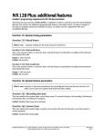
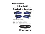
1
Remote IP Feature Phone
Installation Manual
0450-0450
Rev. A
About ESI
ESI (Estech Systems, Inc.) is a privately held corporation based in Plano, Texas. Founded in 1987, ESI
designs and builds innovative telecommunications products for businesses like yours. Because of their
powerful combination of value and features, ESI products are consistently recognized by industry
publications and leaders.
Copyright © 2003 ESI (Estech Systems, Inc.).
IVX is a registered trademark of Estech Systems, Inc. Microsoft, MS and Windows are registered trademarks of Microsoft
Corporation. Intel is a registered trademark of Intel Corporation. Ethernet is a registered trademark of the Xerox Coporation.
Linksys is a registered trademark of Linksys Group, Inc. DIVA is a trademark of Eicon Networks Corporation. Information contained
herein is subject to change without notice. ESI products are protected by U.S. Patents No. 6,067,349 and 6,252,944, and others
pending. ESI is an ISO 9001-certified company. Visit ESI on the Web at www.esi-estech.com.
Table of contents
General description..................................................................................................................................................A.1
Esi-Tools........................................................................................................................................................................................................A.1
Programming information .......................................................................................................................................B.1
Main office parameters ................................................................................................................................................................................B.1
Remote site parameters ..............................................................................................................................................................................B.2
Remote Phone MAC address.....................................................................................................................................................................B.2
Programming the IP PBX and Remote IP Feature Phone....................................................................................C.1
Programming the IP PBX for remote access.............................................................................................................................................C.1
Programming the Remote IP Feature Phone............................................................................................................................................C.1
Configuring the remote modem router..................................................................................................................D.1
xDSL modem with a static IP address .......................................................................................................................................................D.2
Cable modem with a static IP address.......................................................................................................................................................D.3
Dedicated ISDN with a static IP address ...................................................................................................................................................D.4
Dial-up ISDN.................................................................................................................................................................................................D.5
Configuring a NAT router for DHCP ...........................................................................................................................................................D.7
Configuring a NAT router for DHCP ...........................................................................................................................................................D.7
Configuring a NAT router for PPPoE..........................................................................................................................................................D.9
Connecting the Remote IP Feature Phone............................................................................................................E.1
Network guidelines .................................................................................................................................................. F.1
LAN................................................................................................................................................................................................................ F.1
WAN.............................................................................................................................................................................................................. F.2
Troubleshooting ...................................................................................................................................................... G.1
Troubleshooting tools.................................................................................................................................................................................. G.1
Troubleshooting scenarios ......................................................................................................................................................................... G.1
Appendix I: Using PING to verify the remote site/ main office connection......................................................H.1
Appendix II: Using TRACERT .................................................................................................................................. I.1
Appendix III: Installing the TCP/IP protocol in Windows 95/98 .......................................................................... J.1
Appendix IV: IP addressing information worksheet ...........................................................................................K.1
Appendix V: Address recovery at the remote site............................................................................................... L.1
Appendix VI: Discovering the remote-access IP address for the remote IP PBX ........................................... M.1
Index
(This page included for pagination purposes only.)
Remote IP Feature Phone Installation Manual
General description
General description
This manual provides step-by-step instructions and guidelines for your use in installing the Remote IP
Feature Phone. The Remote IP Feature Phone is compatible with a wide range of broadband access
devices and Internet service providers (ISPs). Providing instructions for all types of broadband access
equipment would not be possible in a reasonably sized document; instead, this manual deals with
several common devices. With a good understanding of the installation procedures within this manual,
the Installer should be able to determine how to install the Remote IP Feature Phone with other access
devices. Additional support is available from ESI Sales Engineering.
The E-Class Remote IP Feature Phone is designed specifically to work with the following ESI IP PBX
systems: IP 200e, IP 40e, IVX® 128e and IVX 72e. Installation of a Remote Network Card (RNC) in the
IP 200e and IP 40e is required to support operation of the Remote IP Feature Phone. Installation of a
Local Network Card (LNC) and a RNC is required in the IVX 128e and IVX 72e.
Note: For proper installation and configuration of an RNC, follow the procedures in the appropriate Installation
Manual for the system involved, the Remote Network Card Installation Guide and — if the system is
IVX 128e or IVX 72e — the Local Network Card Installation Guide. You can find all E-Class technical
documents on the Technical Resource Guide CD-ROM.
Esi-Tools
Important:
Prior to receiving the Remote IP Feature Phone you should have completed, and submitted to
ESI Sales Engineering, a Network Qualification Checklist for Remote IP Feature Phone
Installations. If the checklist has not been completed and/or approved by ESI Sales
Engineering, DON’T proceed with the installation. The purpose of the checklist is to ensure
that the installation will be successful and trouble-free. Contact ESI Sales Engineering with
questions on the suitability of a potential installation site.
The Esi-Tools PC-based applications suite includes several easy-to-use utilities to assist the installer
with setting up and troubleshooting Remote IP Feature Phone installations. Among these:
• Esi-Networx — A network performance measurement and analysis tool; can be used in place of the
standard Windows®/MS®-DOS PING and TRACERT commands.
• Esi-Address — Used to program and upgrade local and Remote IP Feature Phones.
• Esi-Check — Provides continuous monitoring of IP link quality for the Remote IP Feature Phone.
For more information, refer to the Esi-Tools Product Overview and User’s Guide or contact your ESI
sales representative to learn how you may obtain Esi-Tools.
If you don’t have Esi-Tools, you may find this manual’s appendices especially useful:
• Appendix I — Using the PING command to verify the remote site/home office connection
• Appendix II — Using the TRACERT command
• Appendix III — Installing the TCP/IP protocol
• Appendix IV — IP address worksheet
• Appendix V — Address discovery at the remote site
• Appendix VI — Discovering the IP PBX’s remote-access IP address
A.1
General description
Remote IP Feature Phone Installation Manual
(This page included for pagination purposes only.)
A.2
Remote IP Feature Phone Installation Manual
Programming information
Programming information
Before programming the Remote Phone and the IP PBX, addressing and access information should be
defined and collected.
Important:
We have provided the worksheet in Appendix IV to help you collect the information described on
these pages. Fill out this worksheet and use it during the programming operation.
The private, or local, IP addresses and UDP port numbers should be agreed upon with the site network
administrator or the person designing the network. The ISP provides the public IP addresses. Contact
the ISP if the network administrator cannot provide this information.
In most cases, there won’t be a network administrator for the remote site; this will be typical for the
home office installation. Appendix V, “Address discovery at the remote site,” provides step-by-step
procedures for determining existing addressing information, such as the gateway address. This
appendix also provides guidelines for selecting a private IP address and a UDP port for the Remote IP
Feature Phone.
There may also be cases where the main office network administrator is not available. Appendix VI provides
a procedure to “discover” the needed main office addressing information. This will be useful for main office
installations where the IP PBX has already been configured for Remote Phone or Esi-Link operation.
Main office parameters
Note: If the main office IP PBX has been previously configured for a remote phone or Esi-Link
multi-site access, these programming parameters will already be programmed into the IP PBX. The same
addressing parameters should be used unless an alternate gateway will be used at the main office for
this Remote Phone. (Refer to Figure 1, page B.2, for examples.)
• PBX private IP address — The address IP PBX uses on the internal network at the main office.
[Item 1 in Figure 1, page B.2.]
• PBX default gateway IP — The internal network address of the default gateway. [Item 2 in
Figure 1, page B.2.]
• Remote-access IP address — The public or private IP address used for remote access to the IP
PBX. [Item 3 in Figure 1, page B.2.] This is typically the public IP address of the main office gateway.
This is programmed in Function 821 and Function 31. If the main office has a single gateway, the
remote-access IP address will be the same in both programming steps; this will be true in the vast
majority of installations. However, in some installations, there may be two or more gateways at the
main office.
If Function 821 has been previously programmed for one gateway, and the remote phone
being programmed will use the other gateway, don’t change the remote-access IP address in
Function 821; instead, enter the alternate remote-access IP address in Function 31.
• Base UDP port number — The base UDP port number used by the IP PBX for access through the
main office gateway.
Important:
If the Remote IP Feature Phone will connect via the Internet, the remote-access IP address must
be a public address (assigned by the ISP).
B.1
Remote IP Feature Phone Installation Manual
Programming information
Remote site parameters
• IP address — The address the Remote Phone will use. This can be either a public or private
address. [Item 4 in Figure 1, below.] The Remote Phone can only use a static address. If a static
public address is not available a NAT router must be used. In that case, the Remote Phone IP
address will be a private address on the remote site network. (Note that the Remote Phone IP
address cannot be the same as the PC address [Item 5 in Figure 1, below].)
• Remote Phone gateway IP — If the Remote Phone uses a private IP address, this will be the
internal network address of the remote site gateway. [Item 6 in Figure 1, below.] If the Remote Phone
use a public IP address, this will be the ISP gateway’s IP address. This is commonly referred to as
the default gateway.
• UDP Port number — The port number that the remote phone will use for access through the
gateway at the Remote site.
Remote Phone MAC address
The Remote Phone MAC address is unique to each Remote Phone, and is preprogrammed. You’ll need
this address for programming the IP PBX.
To determine the MAC address for a Remote Phone, power up the phone and wait; soon, the Remote
Phone’s display will show the MAC address (for approximately 30 seconds).
Figure 1
B.2
Remote IP Feature Phone Installation Manual
Programming the IP PBX and Remote IP Feature Phone
Programming the IP PBX
and Remote IP Feature Phone
The section outlines the process for configuring the IP PBX and the Remote IP Feature phone for
remote operation. This provides a quick overview. For complete instructions, please refer to Function 8
in the appropriate E-Class Installation Manual (IP E-Class or IVX E-Class).
Programming the IP PBX for remote access
If the IP PBX has previously been programmed for remote operation, these steps don’t have to
be repeated.
Important:
DO NOT connect the Remote IP Feature Phone during these steps.
1. Use Function 821 to program the IP PBX address information. This includes:
• PBX private IP address
• PBX default gateway IP
• Remote-access IP address
• Base UDP port number
2. If this is the first remote connection made to this IP PBX, verify that the main office gateway is
properly configured for the remote-access IP address and UDP port number.
Programming the Remote IP Feature Phone
Important:
Portions of this programming must be done prior to connecting the Remote IP Feature Phone to
the main office local network. Power up the phone but do not connect the Remote IP Phone until
instructed. Perform the programming from a local IP phone on the network.
1. Use Function 31 to program the Remote IP Feature Phone parameters into the IP PBX. These
parameters include:
• Extension number
• Type = Remote Phone
• IP address that the Remote IP Feature Phone will use at the remote site
• MAC address (0030 4Dxx xxxx as read from the Remote IP Feature Phone display)
• Gateway address at the remote site
• UDP port number that the Remote IP Feature Phone will use at the remote site
• Remote-access IP address for the IP PBX
Note: Here, you will be prompted to save the settings you have programmed so far, here.
Press # to save the information and continue.
• User name
• CO line groups
• Call forwarding extension for the day mode
• Call forwarding extension for the night mode
The information is now stored in the IP PBX.
C.1
Programming the IP PBX and Remote IP Feature Phone
Remote IP Feature Phone Installation Manual
2. Now, connect the Remote IP Feature Phone to the local network. The phone should connect to the
network and become operational.
3. The Function 31 parameters now need to be downloaded to the phone. Repeating the Function 31
programming steps does this. Enter the extension number and press #. You don’t have to re-enter
the rest of the parameters; just push # to confirm each parameter. Then, when you exit Function 31,
the parameters will be sent to the Remote IP Feature Phone.
The phone is now ready for installation at the remote site.
The process described here requires that the programming of the IP PBX and Remote IP Feature Phone
be performed at the main office before installing the phone at the remote site. Esi-Tools includes two
software tools, Esi-Access and Esi-Address, that can be used to minimize the amount of travel required to
install a Remote IP Feature Phone. This will be very useful in cases wherein the remote site is far from the
main office. Use Esi-Access to connect remotely to the main office IP PBX for programming in Functions 31
and 821; use Esi-Address to download the addressing information to the Remote IP Feature Phone.
Refer to each software tool’s respective User’s Guide for instructions.
C.2
Remote IP Feature Phone Installation Manual
Configuring the remote modem/router
Configuring the
remote modem router
This section provides step-by-step procedures for configuring different types of modems that are
commonly used at remote sites. These include the following:
• xDSL modem with a static IP address
• Cable modem with a static IP address
• Dedicated ISDN
• Dial Up ISDN (DIVA LAN ISDN modem)
These procedures assume that the remote access device may or may not be configured for normal data
access from the remote site computer(s). For this purpose, the first part of each procedure includes
steps for configuring the remote site computer and modem device for basic operation. Steps are then
provided for adding the Remote Phone addressing information. If basic data access has already been
established it will not be necessary to repeat the first part of the procedure, proceed to the section for
adding the Remote Phone Addressing.
In some areas, cable modem and xDSL access are offered without static IP addressing. This can be
done with either dynamic addressing (DHCP) or Point-to-Point Protocol over Ethernet (PPPoE). In both
cases a Network Address Translation, or NAT, router will be required. The NAT router will be used
between the modem and the Remote Phone. The following procedures are included and must be
performed in addition to configuring the modem:
• Configuring a NAT router to support DHCP
• Configuring a NAT router to support PPPoE
D.1
Configuring the remote modem/router
Remote IP Feature Phone Installation Manual
xDSL modem with a static IP address
Configuring the PC
1. Configure the PC to use a static IP address:
• Click on the Start Menu, choose Settings, then choose Control Panel.
• Double click the Network icon. The Network dialog box appears.
• Choose the TCP/IP protocol. (If you do not see TCP/IP, please refer to Appendix III for
instructions for installing TCP/IP.) You may have multiple instances of the protocol bound to
different adapters. If so double-click on the TCP/IP that appears to the network interface card
(NIC) installed in your computer.
• Click on the IP address tab, and ensure that the radio button next to Specify an IP address is
filled in.
o Enter the IP address assigned to you by the ISP.
o Enter the subnet mask assigned to you by the ISP.
• Click on the DNS tab.
Ensure the bullet next to Enable DNS is selected.
Enter the Host and Domain. (The host name is the name of the computer, and the domain
is supplied by the ISP.)
o Enter the IP addresses of the DNS servers assigned to you by the ISP. (If unsure of these
addresses, contact the ISP.)
• Click on the Gateway tab.
o
o
Enter the gateway IP address assigned by the ISP under New Gateway, then click the
Add button.
• Click on the OK button.
o
• The PC will display a message, “You must restart your computer for the new settings to take
effect.” Click the Yes button.
2. When the PC boots back up, test the Internet connection using the DOS PING command
(refer to Appendix I for additional instructions).
If the PING test fails, check the TCP/IP setting again to make sure a typo did not occur. If the
settings look right, contact the ISP’s Technical Support Center and verify the IP address information.
Also, check with the ISP to make sure that the circuit is operating correctly.
Once the PING test is successful, you are ready to configure the ESI IP Remote Feature Phone for use
with the xDSL modem.
Adding the Remote Phone addressing
If a static address is assigned to the remote phone, no further programming of the xDSL modem is
required. Proceed to “Connecting the Remote Phone” (page E.1).
D.2
Remote IP Feature Phone Installation Manual
Configuring the remote modem/router
Cable modem with a static IP address
Configuring the PC
1. Configure the PC to use a static IP address:
• Click on the Start Menu, choose Settings, then choose Control Panel.
• Double click the Network icon. The Network dialog box appears.
• Choose the TCP/IP protocol. (If you do not see TCP/IP, please refer to Appendix III for
instructions for installing TCP/IP.) You may have multiple instances of the protocol bound to
different adapters. If so double-click on the TCP/IP that appears to the network interface card
(NIC) installed in your computer.
• Click on the IP address tab, and ensure that the radio bullet next to Specify an IP address is
filled in.
o Enter the IP address assigned to you by the ISP.
o Enter the subnet mask assigned to you by the ISP.
• Click on the DNS tab.
Ensure the bullet next to Enable DNS is selected.
Enter the Host and Domain. (The host name is the name of the computer, and the domain
is supplied by the ISP.)
o Enter the IP addresses of the DNS servers assigned to you by the ISP. (If unsure of these
addresses, contact the ISP.)
• Click on the Gateway tab.
o
o
Enter the gateway IP address assigned by the ISP under New Gateway, then click the
Add button.
• Click on the OK button.
o
• The PC will display a message, “You must restart your computer for the new settings to take
effect.” Click the Yes button.
2. When the PC boots back up, test the Internet connection to the main office gateway using the DOS
PING command (refer to Appendix I for additional instructions).
If the PING test fails, check the TCP/IP setting again to make sure a typo did not occur. If the
settings look right, contact the ISP’s Technical Support Center and verify the IP address information.
Also, check with the ISP to make sure that the circuit is operating correctly.
Once the PING test is successful, you are ready to configure the ESI IP Remote Feature Phone for use
with the cable modem.
Adding the Remote Phone addressing
If a static address is assigned to the remote phone, no further programming of the cable modem is
required. Proceed to “Connecting the Remote Phone” (page E.1).
D.3
Configuring the remote modem/router
Remote IP Feature Phone Installation Manual
Dedicated ISDN with a static IP address
Configuring the PC
1. Configure the PC for a static IP address:
• Click on the Start Menu, choose Settings, then choose Control Panel.
• Double click the Network icon. The Network dialog box appears.
• Choose the TCP/IP protocol. (If you do not see TCP/IP, please refer to Appendix III for
instructions for installing TCP/IP.) You may have multiple instances of the protocol bound to
different adapters. If so double-click on the TCP/IP that appears to the network interface card
(NIC) installed in your computer.
• Click on the IP address tab, and ensure that the radio bullet next to Specify an IP address is
filled in.
• Enter the IP address assigned to you by the ISP.
• Enter the Subnet Mask Assigned to you by the ISP.
• Click on the DNS tab.
• Ensure the bullet next to Enable DNS is selected.
• Enter the Host and Domain. (The Host name is the name of the computer, and the Domain is
supplied by the ISP.)
• Enter the IP addresses of the DNS Servers assigned to you by the ISP. (If unsure of these
addresses, contact the ISP.)
• Click on the Gateway tab.
Enter the gateway IP address assigned by the ISP under New Gateway, then click the
Add button.
• Click on the OK button.
o
• The PC will display a message that read “You must restart your computer for the new settings to
take effect.” Click the Yes button.
2. When the PC boots back up, test the Internet connection to the main office gateway using the DOS
PING command (refer to Appendix I for additional instructions).
If the PING test fails, check the TCP/IP setting again to make sure a typo did not occur. If the
settings look right, contact the ISP’s Technical Support Center and verify the IP address information.
Also, check with the ISP to make sure that the circuit is operating correctly.
Once the PING test is successful, you are ready to configure the ESI IP Remote Feature Phone for use
with the ISDN circuit.
Adding the Remote Phone addressing
If a static address is assigned to the Remote Phone, no further programming of the ISDN modem is
required. Proceed to the section “Connecting the Remote Phone” (see page E.1).
D.4
Remote IP Feature Phone Installation Manual
Configuring the remote modem/router
Dial-up ISDN
This procedure is specifically for the DIVA™ LAN ISDN Modem. Other ISDN dial-up modems will be
similar. Refer to the Installation Manual for the specific modem being installed.
Configuring the modem
1. Retrieve the DIVA LAN ISDN Modem Quick Install Guide that came with the modem.
2. Turn to Step 4 of the Quick Install Guide. Item 2 under Step 4 will quickly explain how the user’s PC
needs to be set up. The PC must be configured to use DHCP (or as stated in the Windows network
properties, “obtain an IP address automatically”):
• Click on Start, choose Settings, then choose Control Panel.
• Double click the Network icon. The Network dialog box appears.
• Choose the TCP/IP protocol. There may be multiple instances of the protocol bound to different
adapters. Click the TCP/IP that appears for the network interface card (NIC) installed in the
user’s PC.
• Click on the IP address tab, and ensure that the radio button next to Obtain IP address
automatically is filled in.
• Click on OK; reboot the PC if needed.
3. Complete the remainder of Step 4 of the Quick Install Guide.
4. Follow Step 5 instructions until item number 9b. Enter the phone numbers assigned to the ISDN lines.
5. Follow item number 10 instructions.
• In the Primary and Secondary telephone numbers, enter the Dial Up access number supplied by
the ISP.
• The bottom two fields require the DNS addresses. The ISP also supplies these addresses. Then
click Next.
6. Set up the Cost Control settings if needed, then click on Next.
7. You will see the Review and Save window. Please verify all of the information on this screen. If an
item needs changing, click on Back. If the modem isn’t connected to the ISDN line, click on Save; if
the modem is connected to the ISDN line, then click on Save + Test. This will save the configuration
you just made, and test the settings.
8. If the modem is connected to the ISDN lines, and the test passes, please continue on to the next
step. If the modem did not pass the test, please verify that all the information was entered correctly.
If the modem is set up properly and still cannot pass the test, contact the ISP’s Technical Support
Center.
9. After the modem passes the test, verify the Internet connection to the main office gateway using the
DOS PING command. Refer to Appendix I for additional instructions. If the PING test fails, correct
the problem before proceeding.
D.5
Configuring the remote modem/router
Remote IP Feature Phone Installation Manual
Adding the Remote Phone addressing
The DIVA LAN ISDN Modem has built-in network address translation (NAT) to allow multiple hosts to
use the ISDN connection to the Internet and to provide limited security for those hosts. Please follow the
following steps to add the Remote Phone address and UDP Port to the NAT mapping.
1. On the user’s PC (assuming it’s properly configured to use the modem), open a Web browser and,
in the address field, enter the IP address of the modem. By default, that address is 192.168.1.1.
2. The Web browser will load the configuration screen and should ask for your password. Enter the
system password if required.
3. You should now be at the main Configuration menu. To allow the traffic bound for the phone
through the modem you will need to create a static NAT mapping (in addition to the following, you
can find instructions for this in the DIVA LAN ISDN Modem User’s Guide.)
• Click on IP.
• On the IP menu, click NAT Static Mappings.
• On Map 1, under the Protocol choose UDP.
• Under the server port, enter the UDP port the Remote IP Feature Phone will be using.
For the server IP address for Map 1, enter the IP address of the phone.
• Now click on Save, then click on Reset.
4. When the modem comes back on-line, proceed to “Connecting the Remote Phone” (page E.1).
D.6
Remote IP Feature Phone Installation Manual
Configuring the remote modem/router
Configuring a NAT router for DHCP
The following instructions were written for the Linksys Etherfast Cable/DSL Router model Numbers
BEFSRU31, BEFSR41 v.2, and BEFSR11. The steps will be similar for other NAT routers. Refer to the
router’s User’s Guide for the specific instructions.
1. Retrieve the Linksys Etherfast Cable/DSL Router User’s Guide that came with the router.
2. The user’s PC must be configured to use DHCP (or, as stated in the Windows network properties,
“Obtain an IP address automatically”):
• Click on the Start Menu, choose Settings, then choose Control Panel.
• Double click the Network icon. The Network Dialog Box appears.
• Choose the TCP/IP protocol. (If you do not see TCP/IP, please see page J.1 of these
instructions.) Multiple instances of the TCP/IP protocol bound to different adapters may appear. If
so double click the TCP/IP that appears to the network interface card (NIC) installed in the PC.
• Click on the IP address tab, and ensure that the bullet next to “Obtain IP address
Automatically” is filled in.
• Click OK, and reboot the PC if needed.
3. Connect the router per the instructions in the User’s Guide.
4. Once the router is connected to the modem and the PC is connected to the router, open the Web
browser. In the address field of the browser, enter the IP address of the modem. By default, that
address is 192.168.1.1. (For more in-depth instructions for configuring the router, consult the
Linksys Etherfast Cable/DSL Router User’s Guide.)
5. If the PC is configured properly, the Login Screen will appear. Leave the User name field empty;
type the word admin into the password field and press the Enter key.
6. Configure the router based on how the network will be configured.
• Host Name and Domain Name — These will only need to be assigned if the ISP requires them.
The ESI Remote IP Feature phone does not require them.
• LAN IP address — Leave as default.
• WAN IP address — Enter what the ISP has assigned.
• If the ISP has assigned static IP addresses to the site, enter them here. Enter at least the IP
address, the subnet mask, the default gateway, and the DNS IP addresses. Again, your ISP will
assign these to the connection. If it did not give these addresses to you, contact the ISP.
• If the ISP has assigned the connection as DHCP, click the radio button next to Obtain an IP
address Automatically.
7. Click the Apply button.
8. Click the DHCP Tab, and ensure that the Enable radio button is selected. If the network already has
a DHCP server running, click the Disable radio button.
9. Click the Apply button.
10. Restart the Router by powering if off, then on again, and reboot the PC.
11. After the router and the PC have rebooted verify the Internet connection by performing the PING
test as described in Appendix I.
D.7
Configuring the remote modem/router
Remote IP Feature Phone Installation Manual
Adding the Remote Phone addressing
The Linksys Etherfast Cable/DSL router utilizes network address translation (NAT) to allow multiple
hosts to use the modem connection to the Internet and to provide limited security for those hosts.
Please follow the following steps to configure the router. (Instructions for connecting to the configuration
screen can also be found in the Linksys Etherfast Cable/DSL Router User’s Guide. Instructions for
configuring the Linksys router for specific ISPs can be obtained from the Linksys Web site,
www.linksys.com.)
1. On the user’s PC (assuming it’s properly configured to use the modem), open a Web browser and,
in the address field, enter the IP address of the modem. By default, that address is 192.168.1.1.
2. The Web browser will load the configuration screen and should ask for your password. Enter the
system password if required.
3. You should now be at the Setup menu. To allow the traffic bound for the phone through the router,
IP forwarding will need to be configured. (Instructions for setting up IP forwarding can also be found
in the Linksys Etherfast Cable/DSL Router User’s Guide.)
• From the Setup screen, click on the Advanced tab; then, click on the Forwarding tab.
• On the first mapping, which is the first item in the list, enter the UDP port the Remote IP Feature
Phone will be using in the Service Port field.
• Under the Protocol column, choose UDP.
• Under the IP address column, enter the IP address of the phone.
• Click on Apply, then click on Continue. Then restart the router by powering it off, then on again.
When the NAT router comes back online, proceed with installing the Remote IP Feature Phone (see
page E.1).
D.8
Remote IP Feature Phone Installation Manual
Configuring the remote modem/router
Configuring a NAT router for PPPoE
The following instructions are for the Linksys Etherfast Cable/DSL router model numbers BEFSRU31,
BEFSR41 v.2, and BEFSR11. The steps will be similar for other NAT routers. Refer to the router User’s
Guide for the specific instructions. Instructions for configuring the Linksys router for specific ISPs can be
obtained from the Linksys Web site, www.linksys.com.
1. Retrieve the Linksys Etherfast Cable/DSL Router User’s Guide that came with the router.
2. The PC must be configured to use DHCP or, as stated in the Windows Network properties, “Obtain
an IP address automatically.” If you are not familiar with this setting:
• Click on the Start Menu, choose Settings, then choose Control Panel.
• Double click the Network icon. The Network dialog box appears.
• Choose the TCP/IP protocol. (If you do not see it, see “Appendix III: Installing the TCP/IP
Protocol,” page J.1.) You may have multiple instances of the protocol bound to different adapters.
If so, double-click on the TCP/IP that appears for the network interface card (NIC) installed in
your computer.
• Click on the IP address tab, and ensure that the bullet next to Obtain IP address Automatically
is filled in.
• Click OK, and reboot your computer if needed.
3. Connect your router per the instructions on Page 18 of the User’s Guide.
4. Once the router is connected to the modem, and the PC is connected to the router, open the Web
browser and in the address field enter the IP address of the modem. By default, that address is
192.168.1.1. (For more in depth instruction for configuring the router, see page 33 of the Linksys
Etherfast Cable/DSL Router User’s Guide.)
5. If the PC is configured properly, the log-in screen will appear. Leave the User name field empty and
type admin into the password field and press Enter.
6. Configure the router based on how the network will be configured.
• Host Name and Domain Name — These will only need to be assigned if your ISP requires
them. The ESI Remote IP Feature phone does not require them.
• LAN IP address — Leave as default.
7. Enable the router to perform the PPPoE client function.
• From the setup screen, look toward the bottom of the screen. You will see the PPPoE option.
• Click the Enable button.
• Fill in the Username and Password. The ISP should have assigned these.
• Check the box next to the Keep Alive option. This option will allow the connection to remain
open indefinitely.
8. Restart the router by powering it off, then on again, and reboot the PC.
9. Once the router and the PC come back online, test the Internet connection to the main office
gateway using the DOS PING command (refer to Appendix I for additional instructions). If the PING
test fails, correct the problem before proceeding.
10. You are now ready to configure the router for use with the ESI IP Remote Feature Phone.
D.9
Configuring the remote modem/router
Remote IP Feature Phone Installation Manual
Adding the Remote Phone addressing
The Linksys Etherfast Cable/DSL router utilizes network address translation (NAT) to allow multiple
hosts to use the modem connection to the Internet and to provide limited security for those hosts. Follow
the following steps to configure the router. (Instructions for connecting to the configuration screen can
also be found in the Linksys Etherfast Cable/DSL Router User’s Guide.)
1. On the user’s PC open a Web browser and, in the address field, enter the IP address of the
modem. By default, that address is 192.168.1.1.
2. The Web browser will load the configuration screen and should ask for your password. Enter the
system password if required.
3. You should now be at the Setup menu. To allow the traffic bound for the phone through the router,
IP Forwarding will need to be configured. (Instructions for setting up IP Forwarding can also be
found in the Linksys Etherfast Cable/DSL Router User’s Guide.)
• From the Setup screen, click on the Advanced tab; then, click on the Forwarding tab.
• On the first mapping, which is the first item in the list, enter the UDP port the Remote IP Feature
Phone will be using in the Service Port field.
• Under the Protocol column, choose UDP.
• Under the IP address column, enter the IP address of the phone.
• Click on Apply, then click on Continue. Then restart the router by powering it off, then on again.
When the NAT router comes back online, proceed with installing the Remote IP Feature Phone.
D.10
Remote IP Feature Phone Installation Manual
Connecting the Remote IP Feature Phone
Connecting the
Remote IP Feature Phone
Connect the Remote IP Feature Phone directly, or through a hub or switch, to modem or NAT router. At
this point, installation of the Remote IP Feature Phone is similar to that for the IP Local Phone.
1. Use the provided RJ-45 Cat-5 cable to connect from the connector marked NETWORK to the
device (router or DSL or cable modem).
2. If a PC workstation is to be connected through the phone, use a RJ-45 Cat-5 cable to connect
directly from the phone connector marked PC to the RJ-45 connector on the back of the PC.
If a PC is connected to the phone, the PC should be powered up prior to applying power to
the phone.
To power
To
To
3. If a 60-Key Expansion Console is being installed with
supply
LAN
PC
the Remote IP Feature Phone, use the provided
expansion cable to connect between the phone’s
expansion connector (“To 60-Key Console” in
artwork, right) and the connector on the console.
No other connection is needed. The console draws
its power from the IP Phone’s power supply through
the cable.
Handset
4. Connect the handset cord into the phone connector
To 60-Key
marked HANDSET.
Console
5. Connect the power supply module to the Remote IP
Feature Phone.
At this point the Remote IP Feature Phone will power-up and attempt to make connection to the main
office IP PBX. The successful power sequence will be as follows:
Blank display for several seconds
Power-up display
Contacting remote host
Normal Remote Phone display
(with six RNC channels enabled)
Note: The arrows that briefly appear on the display during connection mean:
Ï — Not connecting to remote system.
Ð — Reconnecting to remote system.
E.1
Connecting the Remote IP Feature Phone
Remote IP Feature Phone Installation Manual
Once the Remote IP Feature Phone has connected to the main office IP PBX, perform the following
operations to ensure that full, proper operation has been established.
Note: During these steps, monitor the display for proper indication for each mode.
1. Program a programmable feature key for the extension assigned to this phone.
2. Program another programmable feature key for a local extension in the main office you’ll be calling.
3. Press the MUTE/DND key and verify that the programmable feature key for the Remote Phone
turns amber.
4. Record a message and play it back; listen for audio anomalies.
5. Call the local extension in the main office. Listen for voice quality and ask the person at the other
end how it sounds. Verify that the programmable feature key for the Remote Phone turns red and
the programmable feature key for the local phone in the main office turns green.
6. Make an outside call (dialing 9, 8 or 71—76) through the main office.
The audio quality of the Remote IP Feature Phone should be almost as good as that of a local
IP Phone in the main office. The difference is due to the compression algorithm that makes the Remote
IP Feature Phone feasible. When listening for audio quality, listen for excessive pops, clicks, drop outs,
garbling or unnatural voice modulations.
If the Remote IP Feature Phone is functional but has unacceptable audio quality, the problem likely will
be with the quality of the IP connection between the remote and main office sites.
E.2
Remote IP Feature Phone Installation Manual
Network guidelines
Network guidelines
The following pages outline the minimum cable, LAN and WAN infrastructure needed for the Remote
IP Feature Phone to work correctly. If the infrastructure doesn’t meet these minimums, the system may
not operate reliably. These guidelines also apply to the main office for proper operation of the IP PBX.
LAN
Cabling
• Use Category 5 or better cable that is pinned out to the 568B standard set forth by ANSI/EIA.1
• Check with the customer about whether the cable installation is certified to meet the Cat-5 standard.
If in doubt please use a cable-certifying tool to certify the cable.
Network architecture
Insure that the network architecture is up to par.
• Shared network
– Overall network utilization should be under 30% under normal-working-hour conditions.
– Insure that no hubs are cascaded more than two levels deep and that no loops have inadvertently
been introduced in the hubs on the network.
– Check for excessive collisions or any other network errors. If any errors are found, they will need
to be corrected to ensure proper operation of the IP PBX and Remote Phone. (Usually, high
collision rates and other network errors are due to a faulty network interface card.)
• Switched network
– Check to see if the customer is using any kind of VLAN. If so, meet with the network administrator
to make sure that you understand the VLAN architecture and can engineer the IP system to work
with it.
– Utilization of the busiest network segment should be under 30% under normal-working-hour conditions.
• Impact from other hosts on the network
– Only necessary protocols should be present on the hosts attached to the network. For example, if the
clients aren’t running any IPX applications, then IPX shouldn’t be installed on any workstations.
– Check to make sure that no unnecessary TSR programs are running on the network hosts.
These programs can sometimes cause broadcast storms and other kinds of unnecessary traffic
on the network.
– Make sure sufficient address space is available if the customer wants the Remote Phones in the
same subnet as the other network hosts.
1
American National Standards Institute/Electronic Industries Association.
F.1
Network guidelines
Remote IP Feature Phone Installation Manual
WAN
• Connection types
– We recommend a dedicated or Point-to-Point high bandwidth circuit. For example a point-to-point
T-1, ISDN, or a Frame Relay connection with a high CIR.1 When used with such a connection the
Remote IP Feature Phone will provide consistent high voice quality.
– A remote connect over the public Internet cannot be expected to provide the same voice quality as
a dedicated or point to point connection. In troubleshooting audio problems over such connections,
verify that IP connection is or is not the source of the problem. Bandwidth and/or latency may be
the cause of the problem. If so, this cannot be corrected within the Remote IP Feature Phone or
PBX. The customer’s ISP has control over these issues. An upgrade of the customer’s IP access
may be required.
• Bandwidth
– Insure that the bandwidth for the voice will be available. The easiest way to do that is to attach
sniffer software (such as Esi-Networx) to the connection and gather an hour’s worth of stats during
the busiest time of the day. Record the peak number and multiply by 2. Now take the number of
proposed talk paths and multiply by 22kbps. Add those two numbers together. For example, the
customer has a 256 Kbps DSL line and, during peak times, has a total of 130K of traffic. He wants
12 talk paths. 12*22=264Kbps. 264+260=524Kbps. He will need to upgrade his line.
– If the customer can, it would be preferable to get a CIR for the bandwidth that the customer will
need from his provider.
– If possible, all the remote sites or Remote IP Feature Phone’s service providers work off the same
backbone provider.
• Firewall issues
– If the customer is using a firewall or proxy of some kind, you must have access to open up the
UDP ports for incoming and outgoing traffic. Make sure to set the customer’s expectation that, if
they are going through a firewall, the installer must have access to open UDP ports on the firewall.
If the customer is not comfortable with that, the customer will have to run the phones on a
separate network that doesn’t use the firewall.
• Router issues
– All UDP ports for the phones can be opened for incoming and outgoing traffic. This will mainly be
the case for NAT enabled routers.
– Make sure that the networks that are to be used for the Remote IP Feature Phones or for Esi-Link
are not two private networks away from the public network. This will mainly be the case for newer
DSL and cable modem installations due to the fact that more and more ISPs are using private
networks and NATing new installations behind that private network. They do this to save IP
addresses.
– You must know how to use TRACERT (traceroute) and/or PING to prove to the customer that the
issue they are having is a network issue. If they can PING a host on the remote network and vise
versa, the network is ok, but if they can’t, there are network issues. If you are seeing high latency
numbers from testing with PING, using TRACERT will show that there are too many hops between
networks. That is a network issue that the ISP will have to resolve before the multi-site capabilities
will operate properly. Esi-Networx provides even more information about network issues, and in an
easy-to-understand, graphical format.
1
Committed information rate.
F.2
Remote IP Feature Phone Installation Manual
Network guidelines
• Quality-of-service/voice-quality issues
– A customer using the Internet to transport the voice can expect some voice-quality issues. Check
the connection’s bandwidth utilization of the connection (and recommend that the customer
increase the bandwidth). Using Esi-Networx or the PING and TRACERT utilities will also help you
to narrow the problem down to the unreliable path the packets are required to take while moving
across the Internet.
– If the customer is using a dedicated or point-to-point connection, Esi-Networx can check both the
bandwidth utilization and the end-to-end latency of the line. Normally, the connection will become
saturated due to increased data traffic. Refer the customer to his/her SLA1 and/or CIR to
determine the point-of-contact, to get the issue corrected.
– Use Esi-Check to monitor the quality of the IP connection over time. The user can instantly view the
quality of the link by noting the color of the Esi-Check icon in the Windows system tray.
1
Service-level agreement.
F.3
Network guidelines
Remote IP Feature Phone Installation Manual
(This page included for pagination purposes only.)
F.4
Remote IP Feature Phone Installation Manual
Troubleshooting
Troubleshooting
The purpose of this section is to assist you with issues you may run into while troubleshooting the
Remote IP Feature Phone. One of the most important things to remember is that you need to isolate the
problem as soon as possible so you know who to get involved to assist you in reaching a resolution.
The most frequent question you will get from your customer, or you may have yourself is: “Is it the phone
system, or the network that is the problem?” This section will also help you answer that question.
Troubleshooting tools
These will allow you to better troubleshoot and narrow the issue down to a network issue, or a phone
Issue. If possible, these tools should go in your tool kit you take to the job site.
• Esi-Tools
• A cable certification instrument
• An extra hub and switch
• An extra router
• Extra Cat-5 patch cords — straight-through and a cross-over cable
Troubleshooting scenarios
• One Remote IP Feature Phone is not connecting to the IP PBX.
– If there is a firewall or proxy server check to make sure that the UDP Port for that phone, and for
the IP PBX is open for both incoming and outgoing traffic.
– If the router is using NAT ensure that the UDP ports on that router are all open.
– Check to see if you can PING the router and another host on the network the Remote IP Feature
Phone is on. If the PING is not successful, it is a network issue.
– Check programming to make sure you have enough remote talk paths open.
– Run TRACERT from the network the Remote IP Feature Phone is on. What is the next hop after
the local router? Is it a private IP address? If so, the phone will not work and the network will have
to be either moved to the first level private network or moved to a public IP address range.
• None of the Remote IP Feature Phones are connecting to the IP PBX.
– If there is a firewall or proxy server check to make sure that the UDP port for the IP PBX is open
for both incoming and outgoing traffic.
– If the router is using NAT, ensure that the UDP ports on that router are all open.
– Check to see if you can PING another host outside of the network the IP PBX is on.
– Check programming to make sure you have enough remote talk paths open.
– Check programming to make sure the Remote IP Feature Phone has been programmed correctly.
Check the MAC address, IP address, UDP port, and gateway addresses to make sure they are
all correct.
– Run TRACERT from the network the IP PBX is on. What is the next hop after the local router? Is it a
private IP address? If so the IP PBX will not work with the Remote IP Feature Phone and the network
will have to be either moved to the first level private network or moved to a public IP address range.
G.1
Troubleshooting
Remote IP Feature Phone Installation Manual
• One or all Remote IP Feature Phones is getting only one-way audio or no audio.
– If there is a firewall or proxy server check to make sure that the UDP Port for that phone, and for
the IP PBX is open for both incoming and outgoing traffic.
– If the router is using NAT ensure that the UDP ports on that router are all open.
• One or all Remote IP Feature Phones are having voice-quality issues.
– Is the customer using a dedicated or Point-to-Point high bandwidth circuit? If so check the bandwidth
utilization and latency of that of that line. If either of those are high, refer the customer to the CIR
(and SLA,1 if the customer has one), and have the service provider troubleshoot the line.
– Is the customer using an ISP to transmit the voice across the Internet? If so it is a network issue.
Run PING and TRACERT to show the customer that the latency and number of hops is high. Also,
have the ISP look at the line to make sure that it is provisioned properly and that everything on the
line is running the way it should be. Additionally, recommend that the customer check with other
ISPs in the area about providing service on the corporate and remote ends. If that isn’t feasible, try
to get at least the same backbone carrier between the sites.
1
Service-level agreement.
G.2
Remote IP Feature Phone Installation Manual
Appendix I: Using PING to verify the connection
Appendix I:
Using PING to verify
the remote site/
main office connection
Before connecting the Remote IP Feature Phone at the remote site, verify that an IP connection
can be made to the main office. This section provides a quick method for verifying the connection. If a
problem is found, you must correct it before installing the Remote IP Feature Phone.
Verifying the IP path to the main office can be done quickly from a user PC at the remote site using the
MS®-DOS command PING. PING is used to send an echo request packet to the main office gateway
and verify that an echo response is received. Use the IP PBX’s remote-access IP address for this test.
1. On the user’s PC, bring up an MS-DOS window by doing either of the following:
• Click on the Windows® Start button, select Run, type command and click on Enter.
• If the user has an MS-DOS Prompt item on his/her Start Menu or desktop, click on it.
2. In this window, type ping followed by a space and the IP PBX’s remote-access IP address and
press ENTER. You should receive a message similar to:
Pinging 64.221.73.226 with 32 bytes of data:
Reply from 64.221.73.226: bytes=32 time=2ms TTL=254
Reply from 64.221.73.226: bytes=32 time=1ms TTL=254
Reply from 64.221.73.226: bytes=32 time=1ms TTL=254
Reply from 64.221.73.226: bytes=32 time=1ms TTL=254
Ping statistics for 64.221.73.226:
Packets: Sent = 4, Received = 4, Lost = 0 (0% loss),
Approximate round trip times in milli-seconds:
Minimum = 1ms, Maximum = 2ms, Average = 1ms
In this example, 64.221.73.226 is the address of the main office gateway. This display shows that
you received responses for each of the four pings the PING program sends. If you do receive PING
responses, proceed to “Configuring the remote modem/router” (page D.1).
If a problem exists with the connection, various displays may result. The display below indicates that the
PING packets expired without a response being generated:
Pinging 64.221.73.226 with 32 bytes of data:
Request timed out.
Request timed out.
Request timed out.
Request timed out.
Ping statistics for 64.221.73.226:
Packets: Sent = 4, Received = 0, Lost = 4 (100% loss),
Approximate round trip times in milli-seconds:
Minimum = 0ms, Maximum = 0ms, Average = 0ms
H.1
Appendix I: Using PING to verify the connection
Remote IP Feature Phone Installation Manual
Another possible display indicating a problem is shown here:
Pinging 64.221.73.226 with 32 bytes of data:
Reply from 206.205.233.145: TTL expired in transit.
Reply from 206.205.233.145: TTL expired in transit.
Reply from 206.205.233.145: TTL expired in transit.
Reply from 206.205.233.145: TTL expired in transit.
Ping statistics for 64.221.73.226:
Packets: Sent = 4, Received = 4, Lost = 0 (0% loss),
Approximate round trip times in milli-seconds:
Minimum = 0ms, Maximum = 0ms, Average = 0ms
This display indicates that a device at 206.205.233.145 witnessed the expiration of the PING packet
time-to-live (TTL) and terminated the PING. This indicates the PING address is wrong or there is a
connection problem at the main office.
H.2
Remote IP Feature Phone Installation Manual
Appendix II: Using TRACERT
Appendix II:
Using TRACERT
The MS-DOS command TRACERT (short for trace route) can be used to determine the location of the
problem. At the DOS prompt type tracert followed by the IP PBX’s remote-access IP address.
Here’s an example of a trace route (host names simulated):
C:\WINDOWS\Desktop>tracert 63.211.73.226
Tracing route to 63.211.73.226 over a maximum of 30 hops
1
2
3
4
5
6
7
8
9
10
11
12
13
14
15
16
17
18
19
1
3
94
75
79
80
79
165
165
*
*
*
*
*
*
*
*
*
*
ms
ms
ms
ms
ms
ms
ms
ms
ms
1
2
74
75
79
79
80
166
165
*
*
*
*
*
*
*
*
*
*
ms
ms
ms
ms
ms
ms
ms
ms
ms
1
1
74
75
80
80
80
164
166
*
*
*
*
*
*
*
*
*
ms
ms
ms
ms
ms
ms
ms
ms
ms
10.0.2.1
63.221.73.225
172.20.0.1
fa7-2.core2.blink.net [63.216.17.33]
199.ATM-0.SAC1.BLINK.NET [204.255.174.13]
157.0.XR2.SAC1.BLINK.NET [152.63.51.70]
0.so.TR2.SAC1.BLINK.NET [152.63.3.197]
127.TR2.DCA8.BLINK.NET [146.188.141.117]
296.XR2.TCO1.BLINK.NET [152.63.32.217]
Request timed out.
Request timed out.
Request timed out.
Request timed out.
Request timed out.
Request timed out.
Request timed out.
Request timed out.
Request timed out.
This example shows that the PING request went through nine devices attempting to find a route to
63.211.73.226 before the PING timed out. The first device, at 10.0.2.1, is the local gateway. This shows
that the routing between the PC and local gateway is correct. If this first step times out, the problem is
between the PC and the gateway and may be a problem with the configuration of the gateway. Steps to
take in this case include:
• Verify that the PC is set to automatically obtain an IP address.
• Check the cabling connections.
• Use the applicable procedure in the next section to correct the gateway configuration.
The second step on the trace route is the ISP gateway. In the example, the ISP gateway address is
63.221.73.225. If this step times out, there is not a connection between the local gateway and the ISP
gateway. This again can be a problem with the configuration of the local gateway. Check the gateway
configuration and correct it if necessary. If this doesn’t correct the problem, contact the service provider
for the remote site.
If TRACERT successfully reaches the ISP gateway but involves many hops, the problem could be at
the main office. Possible problems:
• Address used for PING and TRACERT is incorrect.
• Main office gateway is off-line.
• Service to the main office has been interrupted.
Call the network administrator at the main office to check these. If none of these is the source of the
problem contact the ISP.
I.1
Appendix II: Using TRACERT
Remote IP Feature Phone Installation Manual
(This page included for pagination purposes only.)
I.2
Remote IP Feature Phone Installation Manual
Appendix III: Installing the TCP/IP protocol in Windows 95/98
Appendix III:
Installing the TCP/IP
protocol in Windows 95/98
Important:
Have the PC’s Windows CD-ROM close at hand, in case Windows requires files from it during
this procedure.
1.
2.
3.
4.
5.
6.
7.
Click on Start, choose Settings, then choose Control Panel.
Double click on the Network Icon. The Network dialog box appears. Select its Configuration tab.
Click the Add button.
Double-click on Protocol.
Highlight Microsoft under the list of Manufacturers.
Find and double-click TCP/IP in the list to the right.
After a few seconds, the main Network window will appear. The TCP/IP Protocol should now
be listed.
8. Click OK. Windows may ask for the original Windows installation files. Supply them as needed.
9. Windows will ask you to restart the PC. Click Yes.
Important:
Windows NT and Windows 2000 require Administrator rights to install the TCP/IP protocol. We
recommend that a Windows NT/2000-qualified technician perform this task on a PC running
either Windows NT or Windows 2000.
J.1
Appendix III: Installing the TCP/IP protocol in Windows 95/98
Remote IP Feature Phone Installation Manual
(This page included for pagination purposes only.)
J.2
Remote IP Feature Phone Installation Manual
Appendix IV: IP addressing information worksheet
Appendix IV:
IP addressing
information worksheet
Refer to “Programming information” (page B.1) for the definition of the addressing parameters on this
worksheet. Also, Appendices V and VI provide additional help on correctly determining these addresses.
Function 821 programming
PBX private IP address __ __ __. __ __ __. __ __ __. __ __ __
PBX gateway IP address __ __ __. __ __ __. __ __ __. __ __ __
Remote-access IP address __ __ __. __ __ __. __ __ __. __ __ __
Base UDP port __ __ 0 0 0
Function 31 and
Esi-Address programming
Ext
Type
UDP
port
Remote access
IP address
_ _ _ . _ _ _ . _ _ _ . _ _ _ 0304D _ _ _ _ _ _ _ _ _ . _ _ _ . _ _ _ . _ _ _
_____
___.___.___.___
_ _ _ . _ _ _ . _ _ _ . _ _ _ 0304D _ _ _ _ _ _ _ _ _ . _ _ _ . _ _ _ . _ _ _
_____
___.___.___.___
_ _ _ . _ _ _ . _ _ _ . _ _ _ 0304D _ _ _ _ _ _ _ _ _ . _ _ _ . _ _ _ . _ _ _
_____
___.___.___.___
_ _ _ . _ _ _ . _ _ _ . _ _ _ 0304D _ _ _ _ _ _ _ _ _ . _ _ _ . _ _ _ . _ _ _
_____
___.___.___.___
_ _ _ . _ _ _ . _ _ _ . _ _ _ 0304D _ _ _ _ _ _ _ _ _ . _ _ _ . _ _ _ . _ _ _
_____
___.___.___.___
_ _ _ . _ _ _ . _ _ _ . _ _ _ 0304D _ _ _ _ _ _ _ _ _ . _ _ _ . _ _ _ . _ _ _
_____
___.___.___.___
_ _ _ . _ _ _ . _ _ _ . _ _ _ 0304D _ _ _ _ _ _ _ _ _ . _ _ _ . _ _ _ . _ _ _
_____
___.___.___.___
_ _ _ . _ _ _ . _ _ _ . _ _ _ 0304D _ _ _ _ _ _ _ _ _ . _ _ _ . _ _ _ . _ _ _
_____
___.___.___.___
_ _ _ . _ _ _ . _ _ _ . _ _ _ 0304D _ _ _ _ _ _ _ _ _ . _ _ _ . _ _ _ . _ _ _
_____
___.___.___.___
_ _ _ . _ _ _ . _ _ _ . _ _ _ 0304D _ _ _ _ _ _ _ _ _ . _ _ _ . _ _ _ . _ _ _
_____
___.___.___.___
_ _ _ . _ _ _ . _ _ _ . _ _ _ 0304D _ _ _ _ _ _ _ _ _ . _ _ _ . _ _ _ . _ _ _
_____
___.___.___.___
_ _ _ . _ _ _ . _ _ _ . _ _ _ 0304D _ _ _ _ _ _ _ _ _ . _ _ _ . _ _ _ . _ _ _
_____
___.___.___.___
_ _ _ . _ _ _ . _ _ _ . _ _ _ 0304D _ _ _ _ _ _ _ _ _ . _ _ _ . _ _ _ . _ _ _
_____
___.___.___.___
_ _ _ . _ _ _ . _ _ _ . _ _ _ 0304D _ _ _ _ _ _ _ _ _ . _ _ _ . _ _ _ . _ _ _
_____
___.___.___.___
_ _ _ . _ _ _ . _ _ _ . _ _ _ 0304D _ _ _ _ _ _ _ _ _ . _ _ _ . _ _ _ . _ _ _
_____
___.___.___.___
_ _ _ . _ _ _ . _ _ _ . _ _ _ 0304D _ _ _ _ _ _ _ _ _ . _ _ _ . _ _ _ . _ _ _
_____
___.___.___.___
_ _ _ . _ _ _ . _ _ _ . _ _ _ 0304D _ _ _ _ _ _ _ _ _ . _ _ _ . _ _ _ . _ _ _
_____
___.___.___.___
_ _ _ . _ _ _ . _ _ _ . _ _ _ 0304D _ _ _ _ _ _ _ _ _ . _ _ _ . _ _ _ . _ _ _
_____
___.___.___.___
_ _ _ . _ _ _ . _ _ _ . _ _ _ 0304D _ _ _ _ _ _ _ _ _ . _ _ _ . _ _ _ . _ _ _
_____
___.___.___.___
IP address
MAC address
Gateway IP
K.1
Appendix IV: IP addressing information worksheet
Remote IP Feature Phone Installation Manual
(This page included for pagination purposes only.)
K.2
Remote IP Feature Phone Installation Manual
Appendix V: Address discovery at the remote site
Appendix V:
Address recovery
at the remote site
This appendix describes how to discover the remote site IP address and network information you will
need to install the Remote IP Feature Phone.
The remote site information needed includes the following:
• IP address the Remote IP Feature Phone will use.
• Default gateway for the Remote IP Feature Phone.
• UDP port the Remote IP Feature Phone will use.
Determining the IP address to be used for the Remote IP Feature Phone
To find the IP address for the Remote IP Feature Phone, the first piece of information needed is whether
the IP address assigned to the phone will be a public, or private, IP address. This, in part, will be
determined by the ISP.
If the ISP has assigned only one static public IP address or if the ISP will be using DHCP to assign the
hosts on the remote network their IP addresses, then the phone will have a private IP address. This is
because the network will need a NAT router to accommodate more than one host on the network; this
will be the case for most of the lower-end ADSL circuits.
If the ISP has assigned more than one static IP address, the Remote IP Feature Phone will have a
public IP address. This will be the case for most higher-end ADSL, and nearly all SDSL, circuits.
One static Public IP address, or circuit-used DHCP
If the ISP assigned only one static public IP address, or if the circuit uses DHCP to assign the public
addresses, the IP address of the phone will depend on the router used to do the NAT.
A good portion of commercially available NAT routers for home use will use the private Network ID or
subnet of 192.168.1.0 for the internal or private side of the router, and generally the router will be
assigned the first IP address of that Class C range, which is 192.168.1.1. In this case the phone could
use any open IP address on the subnet 192.168.1.0. When selecting the IP address for the phone,
please be aware that, if the router uses DHCP on the private side, you must select an IP address that is
outside of the DHCP range the router will be using.
For example, most Linksys SOHO NAT routers use the DHCP range of 192.168.1.100 through
192.168.1.150 by default. The PC on the remote network will DHCP its address from one of those in the
range, but there is usually no way to be sure which IP address the PC will get. So, to be safe, you
should assign the phone an IP address outside of that range. The range of the DHCP server can be
found in the installation manual for the NAT router that will be used.
The remote phone will also need to know how to get out of the network to contact the IP PBX. This is
accomplished by the phone using the default gateway for the network to find its way to the IP PBX. The
IP address for the default gateway will always be the IP address of the router. (In the above example,
the router would be assigned 192.168.1.1.) The IP address of the router can also be found in the NAT
router’s installation guide.
To determine the UDP port to open up on the NAT router you will need to know the UDP port range
configured on the IP PBX to which the remote phone will be connected. For example: by default the IP
PBX will be using the UDP port range 59000–59999. The IP PBX will, by default, use 59001, and the
phone will use 59XXX where XXX is the extension number. For example: if the phone is extension 111,
then the UDP port would be 59111.
L.1
Appendix V: Address discovery at the remote site
Remote IP Feature Phone Installation Manual
If the NAT router is already in place and you have no documentation for it, and a PC is already configured
to use the NAT router, the following steps will help you gather the needed IP addresses.
Checking existing address information
Important:
The procedure shown below is for use within Windows 95 and 98. However, if you’re using
Windows NT, Windows 2000 or Windows XP:
1. Click on the Windows Start button and select Run. The Run window will appear.
2. Type command and click on OK. This will open a DOS window.
3. Type ipconfig /all and press Enter.
This provides the same information as the Windows 9x procedure shown below, except that the
information appears within a DOS window.
1. Click on the Start button and select Run. The Run window will appear.
2. Type winipcfg and click on OK. The IP Configuration window will appear:
3. Choose the Ethernet adapter in the dropdown box:
L.2
Remote IP Feature Phone Installation Manual
Appendix V: Address discovery at the remote site
4. The IP address field is the IP address assigned to the PC; you should choose an IP address in the
same subnet for the phone.
In this Windows 9x example shown, the IP address is assigned via DHCP. You can tell this by
looking at the Release and Renew buttons. If the PC, as above, is set to DHCP, then those buttons
will be selectable buttons. If the PC is not set to DHCP, then those buttons will be “grayed-out”
(i.e., not selectable).
In either case, you usually will be able to pick a very high IP address in the range, and use that as
the Remote IP Feature Phone’s IP address. To ensure that the IP address you choose is not in use
by another host on the network, PING the IP address you choose for the phone. (For more
information, see Appendix I.) If the PING is unsuccessful, then the IP address is probably available
for use.
5. The Default Gateway shown in the window is the local IP address of the router. Use this local IP
address as the default gateway when programming the Remote IP Feature Phone.
Multiple public IP addresses
If the ISP has assigned multiple public IP addresses to the circuit, consult the ISP’s documentation to
find the range of available IP addresses. (If this documentation is not available, then you will need to
contact the ISP for the range that is available for use.)
You can use the winipcfg command (see previous page) to find the default gateway. If there is not a PC
already operating on the circuit, the ISP will be able to provide you with this information.
The UDP port in this configuration is not important, because there aren’t any NAT routers on the remote
network that will be configured to allow incoming traffic.
Remote sites with multiple Remote IP Feature Phones
If there are to be two or more Remote IP Feature Phones at a single remote site, each remote phone
will need its own IP address. When adding a Remote IP Feature Phone to a site that already has one,
make sure not to use the same IP address for both phones; otherwise, the two phones will interfere with
each other and neither phone will be usable.
Determine the IP address of an existing Remote IP Feature Phone through system programming:
1. From a local IP Phone at the main office, press PROGRAM and then HOLD, followed by the
installer password. Then press # to enter.
2. Enter 3 1 for Function 31 (extension definition and routing).
3. Enter the extension number of the existing remote phone and press #.
4. Press # again. The LCD will display the IP address of the remote extension:
X180 IP ADDRESS
64.220.72.206
5. Write down this address. Press * twice to finish, then either press RELEASE to exit system
programming or enter another extension. Make sure not to use this address for any Remote IP
Feature Phone you add to the site.
Note:
You also can use Esi-Access or Esi-Address remotely to find a Remote Phone IP address.
L.3
Appendix V: Address discovery at the remote site
Remote IP Feature Phone Installation Manual
(This page included for pagination purposes only.)
L.4
Remote IP Feature Phone Installation Manual
App. VI: Discovering the IP PBX’s remote-access IP address
Appendix VI:
Discovering the
remote-access IP address
for the remote IP PBX
Either the main office network administrator or the ISP can provide the public gateway address at the
main office. (This address is used by the Remote IP Feature Phone as the IP PBX’s remote-access IP
address.) However, in the event the network administrator and the ISP can’t be contacted, here is a
simple method for determining the remote-access IP address of the IP PBX.
To find the IP address of the gateway the phone will use as the remote-access IP address, you can run
the TRACERT command (for more information on using this command, see Appendix II) on one of the
PCs, on the main office network, that has access through the router. Normally, any Windows-equipped
PC with Internet and/or e-mail access will have this ability.
1. Click on the Start button and select Run. The Run window will appear.
2. Type command and click on OK. A DOS window will appear.
3. Type tracert -d www.arin.net (where this refers to a Web site; use whichever one
you choose) and press Enter.1
4. After a few moment, the TRACERT command should return a display similar to that shown below.
The first public IP address in the list typically will be the internal, or gateway address of the main
office’s Internet router. The second address will be the public IP address of the main office router;
the Remote Phone will use this public IP address as the remote-access IP address.
C:\WINDOWS\tracert -d www.arin.net
Tracing route to www.arin.net [192.149.252.22]
over a maximum of 30 hops:
1
2
3
4
5
6
7
8
9
10
11
12
13
14
15
16
17
18
1
3
49
47
46
47
52
71
70
69
71
72
72
85
85
86
97
91
ms
ms
ms
ms
ms
ms
ms
ms
ms
ms
ms
ms
ms
ms
ms
ms
ms
ms
1
2
46
46
46
46
51
69
71
69
71
72
72
86
88
87
96
90
ms
ms
ms
ms
ms
ms
ms
ms
ms
ms
ms
ms
ms
ms
ms
ms
ms
ms
1
2
45
46
46
46
52
70
71
69
69
71
71
86
87
88
97
92
ms
ms
ms
ms
ms
ms
ms
ms
ms
ms
ms
ms
ms
ms
ms
ms
ms
ms
10.0.2.1
168.103.194.150
168.103.198.254
168.103.15.29
205.171.25.89
205.171.25.138
205.171.5.169
205.171.8.146
205.171.21.150
205.171.21.102
205.171.4.250
152.63.82.194
152.63.81.14
152.63.0.198
152.63.34.37
146.188.162.165
157.130.35.6
192.149.252.22
This would be the IP PBX’s
remote-access IP address.
Trace complete.
1
The “-d” option keeps the TRACERT command from resolving host names; this speeds up the process.
M.1
App. VI: Discovering the IP PBX’s remote-access IP address
Remote IP Feature Phone Installation Manual
(This page included for pagination purposes only.)
M.2
Index
Bandwidth, F.2
Cable modem, D.1, D.3
Cabling, F.1
Cat-5, E.1, F.1, G.1
CIR, F.2, F.3, G.2
DHCP, D.1, D.5, D.7, D.9, L.1, L.3
DIVA, D.1, D.5, D.6
DNS, D.2, D.3, D.4, D.5
Domain, D.2, D.3, D.4, D.7, D.9
DSL, D.7, D.8, D.9, D.10, F.2
Firewall, F.2
Frame Relay, F.2
Host, D.2, D.3, D.4, D.7, D.9
Internet, A.1, D.2, D.3, D.4, D.5, D.6, D.7, D.8, D.9,
D.10, F.2, F.3, G.2, M.1
IP address, A.1, B.1, C.1, D.1, D.2, D.3, D.4, D.5,
D.6, D.7, D.8, D.9, D.10, G.1, H.1, L.1, L.3, M.1
IP PBX, A.1, B.1, C.1, E.1, E.2, F.1, G.1, G.2, M.1
ISDN, D.1, D.4, D.5, D.6, F.2
ISP, A.1, B.1, D.2, D.3, D.4, D.5, D.7, D.9, F.2, G.2,
I.1, L.1, L.3, M.1
Linksys, D.7, D.8, D.9, D.10, L.1
LNC, A.1
Local Network Card, A.1
MAC, C.1, G.1
Main office, B.1, I.1
MS-DOS, H.1, I.1
Multiple public IP addresses, L.3
NAT, B.2, D.1, D.6, D.7, D.8, D.9, D.10, E.1, F.2, G.1,
G.2, L.1, L.3
Network architecture, F.1
Network Qualification Checklist, A.1
PING command, A.1, D.2, D.3, D.4, D.9, G.2, H.1
PPPoE, D.1, D.9
Quality-of-service, F.3
Remote Network Card, A.1
RNC, A.1
Router, D.7, D.8, D.9, D.10, F.2
TCP/IP, A.1, D.2, D.3, D.4, D.5, D.7, D.9, J.1
TRACERT (traceroute) command, A.1, G.1, G.2, I.1
UDP, B.1, C.1, D.6, D.8, D.10, F.2, G.1, G.2, L.1, L.3
WAN, D.7, F.1, F.2
Windows, D.5, D.7, H.1, J.1, L.2
xDSL, D.1, D.2
(This page included for pagination purposes only.)