1
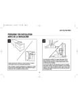
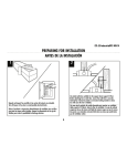
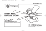
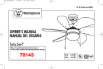
UL_industrial_J
5/23/05
9:57 AM
Page 1
UL-ES-I56/WJ-WH05
OWNER'S MANUAL
MANUAL DEL USUARIO
Industrial
Please write model number here for future reference: /
Por favor, incluya el número del modelo aquí para futura referencia:
N.W. : 6.2 KGS
G.W. : 7.0 KGS
MR
UL_industrial_J
5/23/05
9:57 AM
Page 2
UL-ES-I56/WJ-WH05
SAFETY TIPS
OBSERVE THE FOLLOWING: READ AND SAVE THESE INSTRUCTIONS
WARNING: TO REDUCE THE RISK OF FIRE, ELECTRIC SHOCK, OR PERSONAL INJURY, MOUNT TO OUTLET BOX MARKED "ACCEPTABLE FOR FAN SUPPORT",
AND USE THE OUTLET SCREWS PROVIDED WITH THE OUTLET BOX. MOST OUTLET BOXES COMMONLY USED FOR THE SUPPORT OF LIGHTING FIXTURES
ARE NOT ACCEPTABLE FOR FAN SUPPORT AND MAY NEED TO BE REPLACED. CONSULT A QUALIFIED ELECTRICIAN IF IN DOUBT.
1. Installation work and electrical wiring must be done by qualified person(s) in accordance with all applicable codes and standards (ANSI/NFPA 70-1996), including fire-rated construction.
2. Use this unit only in the manner intended by the manufacturer. If you have any questions contact the manufacturer.
3. After making the wire connections, the wires should be spread apart with the grounded conductor and the equipment-grounding conductor on one side of the outlet box and ungrounded conductor on
the other side of the outlet box.
4. Before you begin installing the fan, Switch power off at Service panel and lock service disconnecting means to prevent power from being switched on accidentally. When the service disconnecting
means cannot be locked, securely fasten a prominent warning device, such as a tag, to the service panel.
5. Be cautious! Read all instructions and safety information before installing your new fan. Review the accompanying assembly diagrams.
6. When cutting or drilling into wall or ceiling, do not damage electrical wiring and other hidden utilities.
7. Make sure the installation site you choose allows the fan blades to rotate without any obstructions. Allow a minimum clearance of 10 feet from the floor to the trailing edge of the blade.
8. To reduce the risk of fire, electric shock, or personal injury, this fan must be mounted to an outlet box marked suitable for fan support. And use mounting screws provided with the outlet box.
(Mounting must support at least 35 lbs.)
9. Do not bend blade holders during installation to motor, balancing or during cleaning. Do not insert foreign object between rotating blades.
10. Attach the mounting bracket using only the hardware supplied with the outlet box. Fan is only to be mounted to an outlet box marked “Acceptable for Fan Support”.
11. To reduce the risk of fire or electric shock, do not use this fan with any solid state fan speed control device, or variable speed control.
12. If this unit is to be installed over a tub or shower, it must be marked as appropriate for the application.
13. NEVER place a switch where it can be reached from a tub or shower.
14. The combustion airflow needed for safe operation of fuel-burning equipment may be affected by this unit’s operation. Follow the heating equipment manufacturer’s guideline safety standards such as
those published by the National Fire Protection Association (NFPA), and the American Society for Heating, Refrigeration and Air Conditioning Engineers (ASHRAE) and the local code authorities.
15. Before servicing or cleaning unit, Switch power off at Service panel and lock service disconnecting means to prevent power from being switched on accidentally. When the service disconnecting means
cannot be locked, securely fasten a prominent warning device, such as a tag, to the service panel.
Phillips Screwdriver
TOOLS REQUIRED
Wire Cutters
Pliers
2
Step Ladder
UL_industrial_J
5/23/05
9:57 AM
Page 3
UL-ES-I56/WJ-WH05
CONSEJOS DE SEGURIDAD
HAGA LO SIGUIENTE: LEA Y GUARDE ESTAS INSTRUCCIONES
ADVERTENCIA: PARA REDUCIR EL RIESGO DE INCENDIO, DESCARGA ELÉCTRICA O LESIONES PERSONALES, MONTE EL VENTILADOR EN UNA CAJA DE EMBUTIR ROTULADA “ADECUADA PARA
VENTILADORES”, Y UTILICE LOS TORNILLOS DE MONTAJE INCLUIDOS CON LA CAJA DE EMBUTIR. LA MAYORÍA DE LAS CAJAS DE EMBUTIR UTILIZADAS NORMALMENTE PARA ARTEFACTOS DE
ILUMINACIÓN NO SON ADECUADAS PARA VENTILADORES Y DEBERÍAN SER REEMPLAZADAS. SI TIENE PREGUNTAS, CONSULTE A UN ELECTRICISTA CERTIFICADO.
1. El trabajo de instalación y el cableado eléctrico los deben efectuar personas calificadas cumpliendo con todos los códigos y las normas aplicables (ANSI/NFPA 70-1996), incluyendo las de incendio.
2. Use esta unidad sólo de la manera en que el fabricante quiere que se haga. Si tiene dudas, llame al fabricante.
3. Después de hacer las conexiones, se deben separar los cables: el conductor de puesta a tierra y el conductor de puesta a tierra del equipo a un lado de la caja de embutir, y el conductor que no
tiene puesta a tierra del otro lado de la misma.
4. Antes de comenzar a instalar el ventilador, apague la alimentación en el panel de servicio y bloquee el medio de desconexión del servicio para evitar que se encienda accidentalmente.
Cuando no se puede bloquear el medio de desconexión del servicio eléctrico, fije de manera segura y un dispositivo de advertencia prominente, como un rótulo, al panel de servicio.
5. ¡Tenga cuidado! Lea todas las instrucciones y la información de seguridad antes de instalar su ventilador nuevo. Revise los diagramas de montaje incluidos.
6. Al cortar o perforar una pared o el cielo raso, no dañe el cableado eléctrico y otras instalaciones de servicios públicos ocultos.
7. Asegúrese de que el sitio para la instalación que escoja permita que el ventilador gire libremente sin obstrucciones. Deje un espacio mínimo de 10 pies desde le piso hasta el borde posterior de la paleta.
8. Para reducir el riesgo de incendios, choques eléctricos o lesiones personales, este ventilador se debe montar sobre una caja de embutir que tenga una marca que indique que es adecuada para
soportar un ventilador. Además debe utilizar los tornillos correspondientes incluidos con la caja de embutir. (El montaje debe soportar por lo menos 35 libras)
9. No doble los soportes para las paletas durante la instalación al motor, al balancear o durante la limpieza. No inserte objetos extraños entre las paletas mientras giran.
10. Fije el soporte de montaje usando sólo la tornillería suministrada con la caja de embutir. El ventilador sólo se debe montar en una caja de embutir marcada “Acceptable for Fan Support”
(Aceptable para soportar ventiladores).
11. Para reducir el riesgo de incendios o choques eléctricos, no use este ventilador con un dispositivo de control de velocidad de estado sólido para ventilador, o un control de velocidad variable.
12. Si esta unidad se instalará sobre una bañera o una ducha, debe estar identificada como adecuada para ese tipo de aplicación.
13. NUNCA coloque un interruptor donde se pueda alcanzar desde una bañera o una ducha.
14. Es posible que la operación de esta unidad afecte el flujo de aire de combustión necesario para la operación segura de equipo que quema combustible. Siga la directrices de seguridad del fabricante
de equipo de calefacción como las publicadas por la Asociación Nacional de Protección Contra Incendios (National Fire Protection Association, NFPA), y la Sociedad Americana para Ingenieros de
Calefacción, Refrigeración y Aire Acondicionado (American Society for Heating, Refrigeration and Air Conditioning Engineers, ASHRAE) y las autoridades del código local.
15. Antes de efectuar tareas de servicio o limpieza en la unidad, apague la alimentación en el panel de servicio y bloquee el medio de desconexión del servicio para evitar que se encienda
accidentalmente. Cuando no se puede bloquear el medio de desconexión del servicio eléctrico, fije de manera segura y un dispositivo de advertencia prominente, como un rótulo, al panel de servicio.
Destornillador Phillips
HERRAMIENTAS NECESARIAS
Pinzas de corte
Pinzas
3
Escalera de mano
UL_industrial_J
5/23/05
9:57 AM
Page 4
UL-ES-I56/WJ-WH05
PREPARING FOR INSTALLATION
ANTES DE LA INSTALACIÓN
1
2
Unpack and inspect fan carefully to be certain all contents are included.
Turn off power at fuse box to avoid possible electrical shock.
Use metal outlet box suitable for fan support (must support 35 lbs).
Before attaching fan to outlet box, ensure the outlet box is securely
fastened by at least two points to a structural ceiling member (a loose
box will cause the fan to wobble).
Use una caja de embutir de metal adecuada para soportar un ventilador
(debe soportar 35 libras). Antes de fijar el ventilador a la caja de embutir
asegúrese de que la misma esté fijada de manera segura en por lo menos
dos puntos a un miembro estructural del cielo raso (una caja suelta haría
que el ventilador oscile).
Quite el envoltorio e inspeccione detenidamente el ventilador para verificar
que todas las piezas estén incluidas. Apague la alimentación en la caja de
fusibles para evitar la posibilidad de descarga eléctrica.
4
UL_industrial_J
5/23/05
9:57 AM
Page 5
UL-ES-I56/WJ-WH05
MOUNTING BRACKET INSTALLATION
INSTALACIÓN CON SOPORTE DE MONTAJE
4
3
Install “J” hook mounting plate to outlet box in ceiling using the screws
provided with the outlet box.
Instale la placa de montaje del gancho “J” a la caja de embutir del
cielorraso con la tornillería suministrada para la caja de embutir.
Loosen set screws on both upper and lower canopies. Install canopies onto
downrod as shown. Thread lead wires through the downrod.
Afloje los tornillos de fijación en los doseles superior e inferior. Instale los
doseles en la varilla vertical como se indica. Pase los hilos conductores a
través de la varilla vertical.
5
UL_industrial_J
5/23/05
9:57 AM
Page 6
UL-ES-I56/WJ-WH05
5
3
4
63
1
5
2
Thread leadwires through the downrod and install crosspin (1) through
yoke (2) and downrod. Install lockwasher (3) and nut (4) and tighten.
Install cotter pin (5).
Loosen set screw in lower canopy and slide to within 1/4” of the motor.
Tighten set screw(s) in the lower canopy. Make sure there is at least 1/4”
clearance maintained around the motor and lower canopy.
Instale el pasador transversal (1) a través de la grapa (2) y el eje central.
Instale la arandela de seguridad (3) y la tuerca (4). Aprete e instale la
clavija hendida(5).
Afloje el tornillo de fijación en el dosel inferior y deslícelo a 1/4” del motor.
Ajuste el(los) tornillo(s) de fijación en el dosel inferior. Asegúrese de que haya
un espacio de por lo menos 1/4” alrededor del motor y el dosel inferior.
6
UL_industrial_J
5/23/05
9:57 AM
Page 7
UL-ES-I56/WJ-WH05
7
8
WALL CONTROL WIRING OPTION
Follow diagram above to make wiring connections for wall control operation.
Note: A professional electrician is recommended for this type of installation.
OPCIÓN DE CABLEADO PARA CONTROL DE PARED
Hang fan on “J” hook. With bracket holding fan assembly, make electrical
connections using the following step for wiring instructions.
Siga las instrucciones del diagrama anterior para hacer las conexiones de
cableado para el ventilador con control de pared. Nota: Se recomienda que
use los servicios de un electricista profesional para este tipo de instalación.
Cuelgue el ventilador del gancho en forma de “J”. Con la pieza de montaje
sujetando el conjunto del ventilador, haga las conexiones eléctricas de acuerdo
a las siguientes instrucciones de cableado.
7
UL_industrial_J
5/23/05
9:57 AM
Page 8
UL-ES-I56/WJ-WH05
93
10
3
After wiring is complete, gently push wires into junction box with wire nuts
pointed upward.
Slide top canopy up and tighten set screw(s).
Una vez que el cableado esté completo, empuje con cuidado los cables
dentro de la caja de empalmes con los conectores de tuerca mirando hacia
arriba.
Deslice el dosel superior y ajuste el(los) tornillo(s) de fijación.
8
UL_industrial_J
5/23/05
9:57 AM
Page 9
UL-ES-I56/WJ-WH05
11
3
Install blades to top of motor using screws and washers . See above
drawing for reference.
Instale las paletas en la parte superior del motor con la tornillería. Utilice
la ilustración anterior como referencia.
9
UL_industrial_J
5/23/05
9:57 AM
Page 10
UL-ES-I56/WJ-WH05
INSTALLING AND WIRING THE WALL CONTROL
INSTALACIÓN Y CABLEADO DEL CONTROL DE PARED
12
Instalación y cableado del control de pared.
Parts:
1. Outlet box
2. Cross Bar Screws
3. Cross Bar
4. Outlet Box Screws
5. Control Unit
6. Terminal Box
7. Front Panel
8. Front Panel Screw
9. Terminal Box Screw
10. Black Supply Lead Wire
11. Black Fan Lead Wire
12. Ground Lead Wire
A. Quite los tornillos de la barra transversal (2) del control de pared y fije la barra
transversal (3) a la caja de embutir.
B. Quite el tornillo del panel delantero (8). Lo necesitará en el paso E. Quite la cubierta
delantera.
C. Conecte el cable guía negro de alimentación (10) en la posición IN y el cable guía negro
del ventilador (11) en la posición OUT en la caja de terminales (6), y ajuste el tornillo de
la caja de terminales (9).
D. Una nuevamente el control de pared a la barra transversal (3).
E. Deslice la cubierta delantera (7) sobre el control de pared y asegúrelo con el tornillo
del panel delantero (del paso B).
Piezas:
1. Caja de embutir
2. Tornillos de la barra transversal
3. Barra transversal
4. Tornillos de la caja de embutir
5. Unidad de control
6. Caja de terminales
7. Panel delantero
8. Tornillo del panel delantero
9. Tornillo de la caja de terminales
10. Cable guía negro de alimentación
11. Cable guía negro del ventilador
12. Cable guía a tierra
Installing and wiring the wall control.
A. Remove the cross bar screws (2) from the wall control and attach the cross bar(3) to
the outlet box.
B. Remove front panel screw (8). Save for use in step E. Remove front cover.
C. Connect black supply lead (10) to IN position, and black fan lead wire (11) to OUT
position on the terminal box (6), and tighten terminal box screw (9).
D. Re-attach wall control to cross bar (3).
E. Slide front cover (7) over wall control and secure with front panel screw (from step B).
10
UL_industrial_J
5/23/05
9:57 AM
Page 11
UL-ES-I56/WJ-WH05
INSTALLING AND WIRING THE WALL CONTROL
INSTALACIÓN Y CABLEADO DEL CONTROL DE PARED
1
2
3
12
4
5
7
8
11
10
6
9
11
UL_industrial_J
5/23/05
9:57 AM
Page 12
UL-ES-I56/WJ-WH05
TROUBLESHOOTING GUIDE
If you have difficulty operating your new ceiling fan, it may be the result of incorrect assembly, installation, or wiring. In some cases, these
installation errors may be mistaken for defects. If you experience any faults, please check this Trouble Shooting Chart. If a problem cannot
be remedied, please consult with your authorized electrician and do not attempt any electrical repairs yourself.
TROUBLE
SUGGESTED REMEDY
1. If fan does not start:
1. Check main and branch circuit fuses or circuit breakers.
2. Check wire connections as performed in step #8 or #12 of installation. CAUTION: Make sure main power is turned off.
3. If the fan still will not start, contact a qualified electrician. Do not attempt to troubleshoot internal electrical connections yourself.
2. If fan sounds noisy:
3. If fan wobbles:
1. Check to make sure all screws in motor housing are snug (not over tightened).
2. Check to make sure the screws which attach the fan blade holder to the motor are tight.
3. Some fan motors are sensitive to signals from Solid State variable speed controls. DO NOT USE a Solid State variable speed control.
4. Allow “break-in” period of 24 hours. Most noises associated with a new fan will disappear after this period.
1. Check that all blade holders are tightened securely to motor.
2. Make sure that canopy and mounting bracket are tightened securely to ceiling joist.
3. If blade wobble is still noticeable, interchanging two adjacent (side by side) blades can redistribute the weight and possibly result in smoother operation.
12
UL_industrial_J
5/23/05
9:57 AM
Page 13
UL-ES-I56/WJ-WH05
GUÍA PARA SOLUCIONAR PROBLEMAS
Si tiene dificultades para hacer funcionar su nuevo ventilador, podría ser a causa del armado, instalación o
cableado incorrectos. En algunos casos, estos errores de instalación podrían ser confundidos con defectos. Si
experimenta alguna falla, consulte esta guía para solucionar problemas. Si no puede solucionar el problema,
consulte a un electricista autorizado y no intente reparar conexiones eléctricas.
PROBLEMA
SOLUCIÓN SUGERIDA
1. Si el ventilador no arranca:
1. Compruebe los fusibles o disyuntores principales y del circuito derivado.
2. Compruebe el cableado del bloque de terminales como lo hizo en el paso No. 8 ó 12 de la instalación.
ADVERTENCIA: Asegúrese de que la alimentación principal esté apagada.
3. Si el ventilador no arranca, póngase en contacto con un electricista calificado. No intente reparar conexiones eléctricas internas.
2. Si el ventilador es ruidoso:
1. Compruebe para asegurarse de que todos los tornillos del alojamiento del motor estén ajustados (no los apriete demasiado).
2. Compruebe para asegurarse de que los tornillos que fijan el soporte de la paleta del ventilador al motor estén apretados.
3. Algunos motores de ventilador son sensibles a las señales de los controles de velocidad variable de estado sólido para motores.
NO USE un control de velocidad variable de estado sólido.
4. Permita el "rodaje" del ventilador durante un período de 24 horas. La mayoría de los ruidos asociados con el ventilador nuevo desaparecerán después de este período.
3. Si el ventilador oscila:
1. Verifique que todos los soportes de las paletas estén firmemente aseguradas al motor.
2. Asegúrese de que el dosel y el soporte de montaje estén firmemente asegurados a la viga del cielorraso.
3. Si la oscilación de la paleta sigue siendo visible, es posible que al intercambiar dos paletas adyacentes (lado a lado) se redistribuya el peso y el funcionamiento sea más suave.
13
UL_industrial_J
5/23/05
9:57 AM
Page 14
UL-ES-I56/WJ-WH05
14
UL_industrial_J
5/23/05
9:57 AM
Page 15
UL-ES-I56/WJ-WH05
PARTS LIST
LISTA DE REPUESTOS
1
#
1
2
3
8
Description
. . . . . . . . . . . . . . . . . Mounting Bracket
. . . . . . . . . . . . . . . . . Blade
. . . . . . . . . . . . . . . . . Wall Control
. . . . . . . . . . . . . . . . . Hardware Pack
No.
1
2
3
8
2
Descripción
. . . . . . . . . . . . . . . . .Soporte de montaje
. . . . . . . . . . . . . . . . .Paleta
. . . . . . . . . . . . . . . . .Control de pared
. . . . . . . . . . . . . . . . .Tornillería
3
15
4
UL_industrial_J
5/23/05
9:57 AM
Page 16
UL-ES-I56/WJ-WH05
Westinghouse Lighting Corporation
12401 McNulty Road
Philadelphia, PA 19154 U.S.A.
Westinghouse Lighting Corporation
12401 McNulty Road
Philadelphia, PA 19154 U.S.A.
Westinghouse Lighting Corporation,
a Westinghouse Electric Corporation licensee
is a registered trademark of
Westinghouse Electric Corporation
Westinghouse Lighting Corporation,
titular de la licencia de Westinghouse Electric Corporation
es una marca registrada de
Westinghouse Electric Corporation
Made in China
© 2005 Westinghouse Lighting Corporation
Fabricado en China
© 2005 Westinghouse Lighting Corporation