1
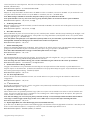
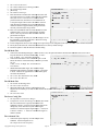
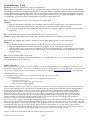
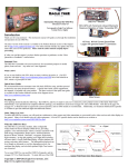
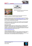
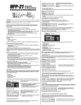
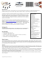
Guardian 2D/3D Stabilizer
Document Version 1.5
Introduction
Thank you for your purchase! Based on Eagle Tree's proven inertial stabilization technology, the Guardian 2D/3D Stabilizer (the
Guardian) stabilizes gas or electric models, wings, foamies, sailplanes, turbines, or just about any other fixed wing model.
To stabilize your model, just mount the Guardian in a level orientation (it can even be mounted
upside down), connect it to your servos and receiver with the included cable, tune it to your
plane with a small screwdriver, and set optional features with your radio sticks. No computer
or additional equipment is required for stabilization. If desired, our powerful PC software
can also be used to quickly configure the Guardian’s advanced features (“micro” USB cable
required, but not included).
This instruction manual will guide you through the installation and operation of your
Guardian. The latest version of this manual is available in the Product Manuals section of the
Support tab on http://www.eagletreesystems.com. The online manual is in full color, and
includes any updates that were made after this manual was produced. Please read the entire
manual carefully before proceeding. If, after you read the manual, you have further
questions or problems, see the “Have Questions or Feedback?” section below.
Packing List
Your package should include the following: The Guardian, the receiver connection harness
with labeled connectors, the quick reference card, and a printed version of this manual.
Specifications
•
•
•
•
•
Input Voltage Range: 4.5v to 16v
Current Draw: Approximately 31mA
Dimensions: 41mm x 22mm x 11mm (1.62 inches x 0.86 inches x 0.42 inches)
Mass: 11 grams (0.4 ounces) including harness
Maximum Servo Current through Guardian: 5 Amps
Table of Contents
Introduction 1
Packing List 1
Specifications 1
Main Features 1
General Safety Precautions 2
Have questions or Feedback? 2
Overview/Quick Start 2
Guardian Physical Connections
and Controls 3
The Receiver Connection
Harness 4
Receiver Requirements 4
Mounting the Guardian in your
Model 6
Preflight Checks 6
First Flight 6
Tuning Stabilization Gains 7
Status LED 8
Mode/Config Switch Behavior 9
The Guardian PC Software 12
Guardian Configuration Page
Software Reference 12
Troubleshooting / F.A.Q. 14
Limited Warranty 14
Main Features
The Guardian 2D/3D Stabilizer has two main modes of operation: 2D Mode and 3D Mode. While in flight, a spare switch on your radio
lets you switch between 2D (wing leveling) mode, 3D aerobatic mode, and no stabilization. Imagine performing a difficult 3D maneuver
with ease, then just flipping a switch to instantly return to level flight! Note: Please see the Tuning Stabilization Gains section for note on
preventing damage from re-leveling too quickly.
2D Mode
When set for 2D Mode, the Guardian provides much smoother flight and wing leveling stabilization for your model, which makes it a lot
easier to adjust and fly your plane. In this mode, the Guardian "remembers" level flight for your model and returns it to level flight when
needed. In 2D mode, flying in moderate wind can seem just as easy as flying in no wind at all!
Additionally, the Guardian provides precise "fly by wire" control, in which it interprets your control stick deflections as command angles
for Pitch and Roll. For example, pushing and holding your control stick left will cause your model to enter a level altitude banked left
turn. This mode is ideal for beginners as well as experts looking for a reduced workload on take-off and landing. It also can be useful for
aerobatic pilots seeking to recover quickly after losing orientation.
The Guardian also includes an advanced “Oscillation Suppression” feature that can quickly detect and eliminate oscillations stemming
from too high gains.
Copyright 2012 Eagle Tree Systems, LLC
Page 1
2D Heading Hold Submode
With 2D Heading Hold submode, the Guardian will assert Aileron deflections to keep your model locked on its current 2D heading.
Whenever the control stick is moved to turn, this heading is reset and subsequently relocked as soon as the stick is centered again.
Automatic Turn Coordination
When enabled, Automatic Turn Coordination will cause the Guardian to employ the “step on the ball” method of actuating your Rudder
for you. As you enter a banked turn, the Guardian will work to coordinate your model for you. This mode is great for models that skid
easily.
3D Mode
In 3D Mode, the Guardian works to smooth out turbulence and stall characteristics to bring stability and precision to your model while
leaving the feel of flying the same as without stabilization. This mode is intended for more advanced pilots looking for improved stability
without compromising on performance and feel.
3D Heading Hold Submode
Centering the control stick in 3D Mode will engage 3D Heading Lock, which will cause your airplane to hold its present flight orientation
(assuming it is aerodynamically able to do so). In this mode, when the control stick is centered the Guardian remembers its current Pitch,
Roll and Heading and works to keep those locked. Moving the control stick immediately resets the locked heading, allowing for
instantaneous transitions from locked maneuvers to dynamic flight. Actuation of the Rudder control will reset just the Yaw axis, without
affecting the lock on Pitch and Roll.
Direct Rate 3D Control Submode
Unlike many other gyro stabilization systems, the Guardian employs Direct Rate 3D Control to translate your stick deflections to angular
rates without forcing you to “fight the gyro.” With this feature enabled, the Guardian interprets your stick deflections as commanded
angular rates and attempts to have your model follow those commands. This way, snap rolls and other high speed maneuvers are possible
without compromising on stabilization effects.
General Safety Precautions
In addition to other warnings and other precautions in this manual, the following should always be observed:
1) The Guardian is intended for recreational use only. Any other use is not supported.
2) Fly safely! Please refer to the American Model Association’s Safety Code at http://www.modelaircraft.org/files/105.PDF, or
the appropriate safety code for your country. Always obey the law when flying.
3) If you have never set up or operated an RC model before, you will need help from an experienced modeler. Local RC clubs are
great ways to meet experienced modelers, and receive the required training.
4) Never operate your model aircraft near or over buildings, power/telephone lines, or other obstacles. Never operate your model
aircraft near or over other people!
5) RC models and accessories are not toys, and should be kept away from children, without proper adult supervision.
6) Be sure to always fly conservatively and exercise common sense, especially while learning to use the Guardian.
Have Questions or Feedback?
Eagle Tree is committed to providing great customer service. If you’ve read the manual and something is not clear, just ask. We’d much
prefer to take the time to answer your questions, rather than having you waste your valuable time struggling with an issue.
To get help, visit the Eagle Tree Guardian 2D/3D Stabilizer support thread at
http://www.rcgroups.com/forums/showthread.php?t=1596644. Chances are someone has posted a solution to your problem already. If
not, posting your problem there will get a very quick response from the Eagle Tree community.
If you prefer to not post on the forum, or you feel there is a problem with your Eagle Tree hardware, please open a support ticket with us
at http://ticket.eagletreesystems.com and we will respond to your support ticket as soon as we can (normally 1-3 business days). Note that
when you create a support ticket, you will be emailed a link that will let you check the status of the ticket. If you do not receive the email,
this most likely means that a spam filter is intercepting emails from Eagle Tree.
Also Eagle Tree greatly values your feedback on how we can improve our products. To leave us feedback for a new feature request or
improvement, either post the feedback on our support thread above, create a support ticket with your feedback, or send feedback at
http://www.eagletreesystems.com/Feature/feature.html
Overview/Quick Start
First, read through the manual to get a “big picture” understanding of mounting, connection, configuration and operation of the Guardian.
Also, consider watching the Guardian tutorial video located at http://youtu.be/Rt8Y3Lxnv-0. While the Guardian has a wealth of
configurable features and options, getting in the air for most airframes requires minimal setup and configuration. At a minimum, the
Copyright 2012 Eagle Tree Systems, LLC
Page 2
Guardian should be connected between your receiver and your servos and then told some basic orientation and trim details of your model.
These steps are detailed as follows. Note: it is assumed here that you have a transmitter switch connected to the Guardian’s Mode/Config
input.
• Connect the Guardian to your receiver using the included servo wire harness. Refer to the Receiver Connection Harness section
for more information.
• Connect your servos to the matching servo output channels on the Guardian. Note that the signal wire should be on top when
the Guardian’s label is facing the sky. See the Wing Type Configuration section for details on specific airframes.
• To reduce the possibility of extreme servo deflection, it is recommended that you disable stabilization at first. There are 3
ways to disable stabilization: If you are using a 3 position Mode/Config switch, move it to the center (disabled) position. If you are
controlling overall Guardian gain with a knob on your transmitter, set your Gain dial to -100% servo deflection (~1.1ms pulse
length) to disable stabilization. If neither of these methods is applicable, turn the Pitch/Roll/Yaw dials on the Guardian to their
centered position, which will also disable stabilization.
• Configure your Guardian and transmitter for your wing type (see the Wing Type Configuration section for more information):
o
Turn off Elevon and V-Tail mixing in your transmitter, if it is enabled. Elevon and V-Tail mixing will be done by the
Guardian.
o
By default, the Guardian is programmed for traditional wing types (mixing disabled). If your model requires elevon or VTail mixing, you can quickly enable this feature by doing the following:
Within 15 seconds of powering on, toggle your Mode/Config switch three times, which is the Toggle Elevon
Mixing switch gesture (move the switch up-down-up-down-up-down if the switch is presently down, or down-updown-up-down-up if the switch is presently up).
Your servos should “twitch” three times to indicate that you have toggled elevon mixing ON/OFF.
Move your control sticks to ensure that the mixing is now enabled. If not, you may need to re-run the Enable
Elevon Mixing step.
• Place your plane on a test bench so its orientation is the same as it would be during straight and level flight.
• Reset your Trims and Level Flight Orientation:
o
Within 15 seconds of powering on, and with your plane still in the orientation of level flight, toggle your Mode/Config
switch once, which is the Reset Level Flight and Trims switch gesture. Your servos should “twitch” once to indicate that
you have reset your controller trims and level flight orientation.
o
If you re-trim your plane or re-mount the Guardian, you will need to do this again to ensure best stabilization performance.
•
Compensate for servo directions and throws:
o
Set your Mode/Config switch to -100% (switch position 2 on a SpektrumTM controller). This activates “2D Mode”
o
Turn up the Overall Gain knob on your transmitter to 0% deflection (100% overall stabilization gain) if you are using the
gain knob.
o
Observe how your servos react as you pitch, roll and yaw your plane.
o
Adjust the Guardian Pitch, Roll and Yaw axis dials with a screwdriver, so the servo deflects in the correct direction to bring
your model back to level, for each axis. A centered dial asserts zero stabilization on that axis. Turning it clockwise or
counterclockwise increases the gain and selects the servo stabilization direction.
• Ensure your Transmitter Pitch/Roll throws are set for 100% if applicable. The Guardian expects full ranges when it interprets
your command stick deflections to determine the desired orientation in 2D Mode.
• Preflight:
o
Check that when you pitch, roll and yaw your
plane while in either 2D or 3D Mode, that your
servos oppose your movements. See the
Preflight Checks section for more information.
o
Do an engine run-up and confirm that the servos
are not moving around randomly due to
excessive vibration or a loosely mounted
Guardian.
o
Range check your model!
Guardian Physical Connections/ Controls
Please refer to Figure 1. The Guardian has the following
Figure 1 – Guardian Connections and Controls
physical connections and controls:
• Port for Receiver Connection Harness – this is where the included harness connects. The servo plugs on the harness then connect to
the appropriate receiver channels. Please see the Receiver Connection Harness section below for more information.
• Servo Connection Ports – connect the appropriate servos to the Guardian here, noting the plug orientation in Figure 1. Please see the
Wing Hookup Configurations section below for more information.
• Yaw, Roll and Pitch gain control dials – these dials set the individual gains for the Yaw (Rudder), Roll (Aileron) and Pitch (Elevator)
axes, as well as setting the direction of stabilizing servo travel, and are adjusted with a small screwdriver. Please see the Tuning
Stabilization Gains section for more information.
Copyright 2012 Eagle Tree Systems, LLC
Page 3
•
•
•
Micro USB port – this port accepts a “Micro B” USB cable (not included). Connection to a PC lets you update the Guardian
firmware, and also configure and tune your Guardian via your PC. Please see the PC User Interface section for more information.
Accessory (Data) Port – this port is for future expansion, and is not used presently. Please let us know how we should use this port!
LED Viewports – for your convenience, the status LED can be seen from both the top and side of the Guardian case. Please see the
Status LED section for more information.
The Receiver Connection Harness
Receiver Connection Harness Pinout
The lightweight receiver connection harness with labeled connectors should make it
easy for you to hook up the Guardian to your receiver.
A diagram of the harness is shown in Figure 2, for your reference. It has the
following labeled receiver connections:
• Ail – (required) Connects to your receiver’s Aileron output channel. Note that
this channel also supplies power and ground to the Guardian and the servos
connected to the Guardian.
• Elv – (required) Connects to your receiver’s Elevator output channel
Figure 2 – Receiver Connection Harness
• Rud – (optional) Connects to your receiver’s Rudder output channel
• Aux - (optional) Connects to your receiver’s Second Aileron or Flaperon output
channel, if needed
• Mod – (optional, recommended) The Mode/Config input connects to either a two-position or three-position switch. It allows you to
switch the Guardian mode during flight and to do radio stick configuration of the Guardian. See the Mode/Config Switch Behavior
section for more information.
• Gain – (optional) The Gain input connects to a knob (or slider) on your receiver, and lets you adjust the overall stabilizer gain during
flight. See the Stabilization “Master Gain” Control section for more information.
Receiver Connection Harness Load Capacity
When connected typically, the Aileron lead of the Guardian’s receiver connection harness takes power from your receiver, and this
powers the servos you have connected to the Guardian. The Receiver Connection Harness is easily capable of handling the power
requirements of typical analog and digital servos.
However, if the servos you have connected to the Guardian are very large, and/or have a combined current draw of greater than
5 amps, an additional power cable is required. Note that if your BEC or receiver battery is rated at 5 amps or less (the vast majority
are), a backup cable should not be needed. Note also that the Aileron lead of the harness should not be excessively warm after flying,
which could indicate that backup power is needed.
If the servos you have connected to the Guardian draw greater than 5 amps all together, there are two ways to supply additional power to
your servos, which will provide additional current carrying capability to the servos you have connected to the Guardian:
1) If you are not using all the servo output connections on your Guardian, a male to male servo wire (with the signal line cut!) can be
connected between a free servo channel on the
Guardian, and a free channel on your receiver.
2) If all the servo connections on the Guardian are being
used, a male/male/female Y cable (ET p/n CAB-Y-1
or similar) with the signal line cut can be used to
provide additional power to the servos, as shown in
Figure 3.
Receiver Requirements
Figure 3 – Providing Backup Power when all Guardian Servo Channels Used
Receiver Connection Requirements
The number of connections between the Guardian and your receiver depends on type and capabilities of your model, the level of Guardian
in-flight control you require, and the number of spare receiver channels you have. For very basic models, the Guardian is capable of
operating with only the Elevator input and Aileron input connected.
BEC/Receiver Battery Power Requirements
The Guardian 2D/3D Stabilizer is sensitive to deep voltage drops, which means that your BEC or receiver battery must be sufficient
to maintain a voltage of at least 3.5 volts, even under full servo load. The Guardian will shut off if the voltage drops below this
level!
Copyright 2012 Eagle Tree Systems, LLC
Page 4
Under normal conditions, the BEC voltage should be at least 4.5 volts to achieve the best stabilization performance. Never
exceed 16V!
If the voltage drops below 3.5 volts for a short period of time, the Guardian will experience a “brownout.” In this case, the Guardian
will attempt to recover gracefully. During recovery, stabilization may be disabled or suffer from performance issues while it does so. If
you experience issues like this in flight, bring the Mode/Config Switch to either 3D Mode or Stabilization Disabled Mode (if your
transmitter is configured for mode control) and land immediately.
If a brownout condition is detected by the Guardian, the LED will blink an error code of four long blinks followed by one short blink. If
this LED signal is ever seen after a flight, it is recommended that the BEC or battery be upgraded. Please see the Status LED section for
more information on how to interpret LED blinks.
Failsafe position of Receiver Inputs
If, after you reset level flight and trims, an input channel should become disconnected from your receiver during flight, it will cause the
Guardian to use the stored trim setting for that servo channel input as a failsafe.
Wing Type Configuration
The Guardian is configurable for most common wing types. By default, it is configured for traditional wing control. Please refer to
Figure 4, which shows the receiver and servo connections for typical wing types.
The Guardian requires unmixed control inputs from your receiver, even if you have a V-Tail or Elevon model. If you have a VTail or Elevon model, the Guardian does the mixing internally, so you will need to change your transmitter configuration to standard wing
type, rather than having your transmitter do the mixing. Note: for airframe types other than standard and dual Aileron/Flaperon, you will
need to be change the “Model Control Type” setting, using either the radio stick configuration or the PC software. See the Menu
Operation section below for more information on changing this setting.
Traditional Models with Single Aileron Servo
•
Model Control Type setting: Standard (this is the default)
•
Guardian Receiver Inputs
o
Receiver Aileron Output → Guardian Aileron In
o
Receiver Elevator Output → Guardian Elevator In
o
Receiver Rudder Output → Guardian Rudder In
o
Guardian Aux-In is not connected
•
Guardian Servo Outputs
o
Guardian Aileron Out → Aileron Servo (if no Aileron
present, connect Rudder Servo to Aileron Out)
o
Guardian Elevator Out → Elevator Servo
o
Guardian Rudder Out → Rudder Servo
o
Guardian Aux Out is not connected
V-Tail with Ailerons
•
Model Control Type setting: V-Tail
•
Guardian Receiver Inputs
o
Receiver Aileron Output → Guardian Aileron In
o
Receiver Elevator Output → Guardian Elevator In
o
Receiver Rudder Output → Guardian Rudder In
o
Receiver Second Aileron Output → Guardian Aux In
(optional)
•
Output
o
Guardian Aileron Out → Aileron Servo
o
Guardian Elevator Out → V-Tail Servo 1
o
Guardian Rudder Out → V-Tail Servo 2
o
Guardian Aux Out → Second Aileron Servo (optional)
Traditional Models with Dual Aileron/ Flaperon servos (with
Transmitter mixing)
•
•
•
Model Control Type setting: Standard (this is the default)
Guardian Receiver Inputs
o
Receiver Aileron Output → Guardian Aileron In
o
Receiver Elevator Output → Guardian Elevator In
o
Receiver Rudder Output → Guardian Rudder In
o
Receiver Second Aileron or Flaperon Output → Guardian
Aux In
Guardian Servo Outputs
o
Guardian Aileron Out → Aileron Servo
o
Guardian Elevator Out → Elevator Servo
o
Guardian Rudder Out → Rudder Servo
o
Guardian Aux Out → Second Aileron or Flaperon Servo
Elevon / V-Tail with no Ailerons
•
Model Control Type setting: Elevon
•
Guardian Receiver Inputs
o
Receiver Aileron Output → Guardian Aileron In
o
Receiver Elevator Output → Guardian Elevator In
o
Receiver Rudder Output → Guardian Rudder In
o
Guardian Aux-In is not connected
•
Output
o
Guardian Aileron Out → Elevon Servo 1
o
Guardian Elevator Out → Elevon Servo 2
o
Guardian Rudder Out → Rudder Servo
o
Guardian Aux Out is not connected
Figure 4: Receiver and Servo Connections for Typical Wing Types
Dual Ailerons/Flaperons
An exception to the unmixed input requirement is made for Dual Aileron and Flaperon models. By default, the Guardian will accept
premixed Dual Aileron or Flaperon inputs to its Aileron and Aux inputs. But, if your controller does not have the capability of
performing Dual Aileron or Flaperon mixing, then the Guardian can be configured to do this for you. See the List of Features and
Options: Onboard Dual Aileron Mixing Enabled menu option for more information.
Copyright 2012 Eagle Tree Systems, LLC
Page 5
Mounting the Guardian in your Model
Please refer to Figure 5, which indicates acceptable and unacceptable Guardian mounting.
Mount the Guardian securely with two sided servo tape, Velcro, or similar, so that it is in line with your direction of flight. It should be
mounted near the model’s center of gravity and level to the horizon when your plane is flying straight and level, but the Guardian will
compensate for small mounting errors.
Choose a mounting location which will
allow the Guardian to be easily
connected to your receiver and servos.
Important: If the Guardian comes
loose from its mounting location
during flight, it will not be able to
correctly stabilize your model! After
mounting, be sure to pull up on the
Guardian with a force greater than
you expect to encounter in flight, to
confirm mounting integrity.
Note: If permanently mounting the
Guardian, ensure that the USB port is
still accessible for PC configuration
and firmware update.
Figure 5 – Good and Bad Ways to Mount the Guardian
Preflight Checks
Before every flight, it is strongly recommended that you perform the following steps:
• Perform your normal preflight check. Ensure your servos respond correctly to your RC control stick commands.
• To test that the Guardian is working, hold the airplane level. Now, pitch, roll and yaw the model. Please see Figure 6. You should
see the control surfaces deflecting appropriately to level the airplane and keep it on a straight heading. If the control surfaces do not
move at all, ensure that the Master Gain knob on your transmitter (if used) is set so that stabilization will occur, and ensure that the
Mode/Config switch (if used) is set for
either 2D or 3D Mode. Important: If
the control surfaces are moving the
wrong direction, you need to reverse
the direction of the appropriate
Guardian Gain Control Dial!
First Flight
To account for trims and mounting errors of
the Guardian within your plane, follow the
instructions in the section titled “Reset Level
Flight and Trims.”
On your first flight, it is recommended that
you do an unpowered hand-toss of your
airplane, if it is capable of hand-toss launches.
If the airplane safely glides to the ground with
little or no input, then your configuration is
correct. If the model oscillates or
overcompensates during the hand-toss, your
Gain is too high.
Once it has been shown that the Guardian has
been correctly configured, perform a run-up
on the ground with stabilization enabled,
while watching your control surfaces for drift.
If it appears as if stabilization is working
properly with the engine active, then throttle
down, perform one last preflight check and
Copyright 2012 Eagle Tree Systems, LLC
Figure 6 – Correct and Incorrect Control Surface Movement
Page 6
take off with power.
Once in the air and only when safe, release the control stick so it sits at zero deflection with 2D Mode enabled. Your airplane should fly
straight and level. If not, your Guardian may be mounted improperly or you need to re-trim your airframe. Disable stabilization by
flipping the Mode/Config switch to the center position (if available). Trim your controller in this mode until the plane achieves level
flight. Land and follow the instructions for “Resetting Trims” on the ground.
Tuning Stabilization Gains
Stabilization Theory
The Guardian 2D/3D Stabilizer uses accelerometers and gyroscopes to measure the orientation of your model relative to the local
direction of Earth’s gravity. In addition, it interprets Pitch and Roll attitudes commanded by your Elevator and Aileron stick movements,
respectively.
With this information, it is able to determine the error between your requested flight attitude and your plane’s true orientation. By passing
this error through a controller algorithm and sending it as servo commands through its Elevator, Aileron and Rudder outputs, the Guardian
can help turn your squirrely model into a smooth-flying wing on rails!
Each axis has a separate gain control dial, which is used to adjust gain on that axis. The Pitch, Roll and Yaw gains are then scaled by the
optional overall “Master Gain” control, which can be mapped to a knob (or slider) on your transmitter. This arrangement allows
individual axis gain adjustment while also providing in-flight overall gain adjustment to compensate for varying conditions and
aerodynamic performance.
In general, the higher the gain, the more responsive and resilient your plane will be to disturbances such as wind, balance and trim issues.
Tuning the gains too high however may result in oscillations of the airframe. It is recommended that the Master Gain control be used to
tune the airframe until it barely oscillates and then be turned back down. This will ensure the best performance while preventing future
oscillations.
Individual Axis Gain Dials
The gain control dials on the Guardian can be used for tuning the individual axes on your airframe. In addition, they allow for the
reversal of the direction of stabilization servo travel. When a dial is centered (with the
“double-dot” dial indication facing upwards, as shown in Figure 7) the gain for that axis is
set to zero. This effectively disables stabilization on that axis.
Note: If you have difficulty seeing the double-dot indication on the dials, you can either
gently rotate the dials counterclockwise and clockwise to find the approximate center point,
or you can use the PC software to visualize the dial settings on your computer screen.
Figure 7 – Guardian Gain Control Dials
When a dial is rotated away from its centered position in the clockwise direction, the gain
for that axis is increased, and the stabilization deflection direction is set to normal. If the
dial is rotated counterclockwise from its centered position, the gain will be increased as well, but the stabilization deflection direction will
be reversed. This allows for stabilization to be tuned for any airframe, regardless of servo orientations.
Stabilization “Master Gain” Control
The Guardian’s Gain input channel, when mapped to a knob (or slider) on your transmitter, serves as a Master Gain control. The Master
Gain multiplies the individual Pitch/Roll/Yaw gains and serves as a way to easily tune all three. If you have an RC controller that has an
analog knob, this can be mapped to the Gain channel to allow for in-flight stabilization gain adjustment. The higher the gain knob setting,
the stronger the Guardian’s stabilization effect will be.
The knob gives the ability to transition smoothly from stabilized flight to un-stabilized flight. Additionally, since changing airspeed can
change your airframe’s flight characteristics, it is often helpful to be able to tune the controller in real-time. When this feature is used
with 2D mode, the stabilizer’s control characteristics vs. the Master Gain control’s position is as follows:
•
•
•
-100% (1.1ms servo pulse): Stabilization is OFF.
-99% to ~0% (depending on Pitch/Roll/Yaw gain values): Medium Stabilization. As the Gain knob is
increased from -100% deflection, the model becomes more stable. Depending on your knob selection
however, the model may still be rolled by strong stick movements or turbulence
~0% to 100% (1.9ms servo pulse, 200% Overall Gain): Maximum stabilization. The model should not roll
over when in this range. Servo commands will become exaggerated, leading to tighter control of the plane.
Oscillations may occur depending on the airframe.
The ranges given above apply when the Guardian gain dials are set to about +/-50° from centered.
Warning: Be careful while tuning the Master Gain. Some airframes may oscillate very strongly at higher gains, possibly
damaging themselves or becoming uncontrollable. To avoid strong oscillations, increase the Master Gain slowly and reduce it as
soon as oscillations are noticed.
Note: If the individual axis gain dials are set to lower values, the effect of the Overall Gain knob will be reduced, and vice versa.
Note: If no connection is made to the Guardian’s Gain input, 100% Overall Gain will be used.
Copyright 2012 Eagle Tree Systems, LLC
Page 7
Oscillations
Sometimes, when the controller gains are set very high or if your model flies at a very high airspeed, oscillations can develop. If
oscillations occur, turn down the Master Gain knob or the specific gain dial for that axis, until the oscillations stop. Other causes of
oscillations include mechanical slop in control surfaces and slow servos. If your model has digital servos, higher gain values may be
possible by increasing the Output Servo Pulse Frequency. See: List of Menu Features and Options: Output Servo Pulse Frequency.
Oscillation Suppression
To help reduce pilot workload, the Guardian will automatically scale down the Overall Gain when it detects oscillations. To do this, it
incrementally scales the Overall Gain down to a minimum of 50% of its currently set value. After the oscillations are eliminated, it will
slowly increase the Overall Gain back up to 100% of its set value or until oscillations are detected again, whichever comes first.
If oscillations occur and subsequently disappear, it is recommended that you slowly reduce your gains to prevent this from happening in
the future.
Do not increase the Overall Gain after an oscillation has been suppressed, since doing so will only cause more oscillations until the
Oscillation Suppression is unable to reduce the Overall Gain sufficiently to be effective.
Preventing Damage from In-Air Recovery
The Guardian is a great tool for beginners looking for a safety net in case of lost orientation or control, however switching to 2D Mode
with a combination of too-high airspeed and gains may cause damage to the airframe. If the model is not structurally capable of pulling
out of a steep dive very quickly, some configuration may be needed to prevent excessive G-Forces. Reduce the Overall Gain (if
connected) during high speed maneuvers or limit the travel of the servos through the PC software’s Expanded / Custom Servo Ranges
configuration tool under the “Servo Config” tab. Test your changes carefully and conservatively.
Tuning for Optimal Gains
While not needed for a good stabilization experience, there is a maximum gain configuration that can be found that will provide the best
flight performance with the Guardian. This entails setting the highest gains for each axis without triggering oscillations. To do this, start
out with the individual gain control dials set for their maximum correct deflections as described in the “Overview/Quickstart” section.
Take off with the Master Gain control knob turned down low and once at a safe altitude and cruise speed, turn it up slowly to enable
stabilization. Continue turning it up until an oscillation occurs. Note which axis upon which it occurs, reduce the overall gain, and land.
Reduce the individual dial gain of the axis that was showing oscillations. Repeat this process until all three axes oscillate at the same
Overall Gain level or no oscillations can be triggered.
Status LED
The Guardian’s LED uses blink sequences to convey information about system status, the current flight mode and any errors that have
been detected.
The LED will turn ON for 2 seconds, and then slowly blink the number representing the Model Control Type currently selected.
(1 blink = Standard, 2 = Elevon, 3 = V-Tail)
LED Indication during Startup
The LED will turn ON for 2 seconds, and then slowly blink the number representing the Model Control Type currently selected. After
this startup blink sequence, the LED will display steady state status. See List of Menu Features and Options: Model Control Type.
LED Indication during Steady State
• Solid On: 3D Mode
• One repeated blink: 2D Mode
• Solid Off: Stabilization Disabled
Additional LED Messages
• 2 repeated blinks: Radio Stick Menu is active
• 3 repeated blinks: USB is connected
• 4 repeated blinks: Error condition. Error type is indicated by a pause and a
number of additional, faster blinks:
o One blink: Brownout – BEC or receiver battery is providing
insufficient power for your servos and the Guardian. See the
Figure 8: LED Operational and Error Codes
BEC/Receiver Battery Power Requirements section above.
o 2 – 5 blinks: Memory / Calibration Errors – Repower the Guardian
to clear. If this problem occurs repeatedly, contact technical support.
o 6 blinks: Sensor Fault – If this problem occurs repeatedly, mechanical stress or damage to the board may have occurred.
o 7 blinks: Internal error. If this problem occurs repeatedly, contact technical support.
Copyright 2012 Eagle Tree Systems, LLC
Page 8
Mode/Config Switch Behavior
The Mode/Config input on the Guardian lets you change your stabilization mode in-flight between 2D
Mode, 3D Mode and Disabled (if a 3 position switch is used). Additionally, you can configure the
Guardian in the field via a series of toggles of the Mode/Config switch (within 15 seconds of Guardian
power up), referred to as “Configuration Gestures”.
Leaving the Mode/Config input disconnected will cause the Guardian to switch to the Default Flight
Mode. The factory default of this setting is “2D Mode.” If you want to use a different mode in this
case, you will need to use the PC software to set the mode, or temporarily connect the Mode/Config
input to change the mode via the radio stick configuration. See the Default Flight Mode menu item in
the List of Features and Options section below.
Figure 9: Mode/Config Switch
Flight Mode Selection
Please refer to Figure 9. The Guardian has three main operating modes (described earlier) that can be set by the Mode/Config switch
position:
• Down: ( Position 2 , -100%, 1.1ms): 2D Stabilization Mode:
• Middle: (Position 1, 0%, 1.5ms, only available if you are using a 3 position switch): None – No stabilization or damping. All
servo signals are directly passed through. (Elevon and V-Tail mixing is still performed)
• Up: ( Position 0, +100%, 1.9ms): 3D Stabilization Mode
Configuration Gestures
Within 15 seconds after Guardian power-on, the Guardian can be configured by toggling the Mode/Config switch back and forth rapidly.
The number of times you toggle the switch determines which configuration step is performed. Note that if you have a 3 position switch,
its center position is not used during toggling. Here is a table of available configuration gestures, and what each does.
Reset Level Flight and Trims: 1 Toggle (up-down if the switch is presently down, or down-up if presently up)
After changing the trims on your controller or mounting orientation, you must let the Guardian know about this change so it can best
control your airplane. Without this information, 3D Heading Lock will not work and stabilization performance will be degraded.
To update the trim and level flight information for your controller in the Guardian, quickly toggle the Mode Switch back and forth once
within the first 15 seconds after power-on. You will know that the level flight orientation and trims have been reset when the servos both
twitch once and then immediately return to normal movement.
If no twitch occurs when executing Reset Level Flight and Trims, it can either be because the switch gesture was not done quickly enough
or within the first 15 seconds following boot. Alternatively, if the Guardian is mounted too far off of level flight (greater than 25 degrees
in either Pitch or Roll), the Reset Level Flight and Trims will fail, presenting no servo twitch.
Reset Trims Only: 2 Toggles (up-down-up-down if the switch is presently down, or down-up-down-up if presently up)
Use this gesture to reset your trims without needing to also reset your level flight orientation.
To quickly update the trims of your plane in the Guardian, quickly toggle the Mode Switch back and forth two times within the first 15
seconds following power-on. (Example: up-down- up-down) You will know that the trims have been reset when the servos both slowly
twitch twice and then immediately return to normal movement.
Toggle Elevon Mixing: 3 Toggles (up-down-up-down-up-down if the switch is presently down, or down-up-down-up-down-up if
presently up)
A shortcut method for switching between normal and elevon mixed airframes.
To quickly switch elevon mixing on and off without needing to go into the Radio Stick Menu or use the PC software, quickly toggle the
Mode Switch back and forth three times within the first 15 seconds after power-on. You will know that the trims have been reset when
the servos both slowly twitch three times and then immediately return to
normal movement. After this, moving your control sticks will reflect the
current mixing configuration.
This action will toggle from Normal or V-Tail Mode to Elevon Mode and
from Elevon Mode to Normal Mode.
Enter Radio Control Stick Menu: 4 Toggles (up-down-up-down-up-downup-down if the switch is presently down, or down-up-down-up-down-updown-up if presently up).
Enters menu mode (described below).
Radio Stick Menu Operation
Figure 10: Menu Navigation and Feedback
The Guardian 2D/3D Stabilizer has many advanced features that can be
Copyright 2012 Eagle Tree Systems, LLC
Page 9
configured through the Radio Stick Menu.
Entering the Radio Stick Menu
Entering the Radio Stick Menu is done by powering the model with the Guardian connected and quickly toggling the Mode/Config
Switch back and forth four times within the first 15 seconds following power-on. One second after the last switch movement, the menu
will be invoked.
You will know that the menu has been invoked when the servos of your model stop their normal stabilization deflections and instead
perform a short twitch followed by no further movement. Also, the status LED will blink in a two blink sequence when the menu is
active.
Menu Navigation
Once in the menu, you will start at menu item #1 in the List of Features and Options section below. The menu items can be navigated by
deflecting the Aileron and Elevator control inputs (your control stick). On a controller where moving the stick to the right and pulling it
back results in negative servo deflections (servo pulse width is shortened), flicking the Aileron input to the right will increase the menu
item number currently being edited, while flicking the Elevator input forward increases the option value for the currently selected item in
the menu.
Menu feedback is reported through the Aileron and Elevator servo outputs, as shown in Figure 10. Each time a new menu item is selected
by flicking the Aileron control, the Aileron servo will “twitch” once, delay 1.5 seconds and then twitch rapidly a number of times that
corresponds to the current menu item number selected. After this, the Elevator servo will count up to the current option value number
selected for that menu item. If a new option value is chosen by flicking the Elevator stick, the Elevator servo output only will twitch once
each time the value is changed, wait 1.5 seconds and then count up to the selected option value number.
Note: If you have your Aileron or Elevator directions reversed on your transmitter, then they will also be reversed as you navigate
the menu!
Note: If you have reduced the rates/deflection ranges configured on your transmitter for your servos, ensure that they are
deflecting at least 50% in order for the menu to detect their movements.
Exiting the Menu
To exit the menu, saving the settings that were changed, quickly toggle the Mode/Config switch back and forth once. (up-down or downup) Once out of the menu, normal servo deflections will start again, using the new settings.
To exit the menu without saving your changes, simply disconnect the receiver battery and repower the plane. The Guardian will boot up
again with its previous settings.
Menu Example
Let’s say you want to set the 2D Heading Hold Gain (menu option 5) to a value of 6. First, toggle the Mode/Config switch 4 times, to
enter menu mode, which starts at menu option 1. Then, you will flick the Aileron stick to the right (or left, if your ailerons are reversed) 4
times, to reach menu option 5. Then, your Aileron should twitch 5 times, to indicate that menu option 5 is selected. And, your Elevator
will twitch a number of times, indicating the present setting for the 2D Heading Hold Gain. Then, flick your Elevator stick up or down, to
increase or decrease the 2D Heading Hold Gain setting, until it reaches 6. At this point, the Elevator should twitch 6 times, which is the
desired setting. To save the new setting, toggle the Mode/Config switch once, which exits menu mode, and returns servo control.
List of Menu Features and Options
The following is an ordered list of all the options adjustable in the Guardian’s Radio Stick Menu, and from the PC software. Note that
options 14 and higher are available only via the PC software.
1. Model Control Type
Enables internal mixing if needed. The Guardian expects only an unmixed servo control signal from the Rx.
1: Standard – Dual ailerons / flaperons are supported.
2: Elevon – The Guardian does the elevon mixing internally. Dual Aileron / Flaperon support
is not available.
3: V-Tail – The Rudder and Elevator channels are mixed internally. Dual ailerons / flaperons
are supported.
2. Center Stick Stabilize Only Mode
This feature is primarily for those who don’t have the Mode/Config switch connected, but want
the benefits of 2D mode while also being able to perform acrobatics. Maximum 2D Mode
stabilization is active when the control stick is centered, and as the control stick is moved from
center, the Overall Stabilization Gain reduces proportionally as illustrated in Figure 11. (2D
Mode Only)
Radio Stick Menu Options: 1: Off; 2: On
3. Center Stick Box Size
The maximum deflection of the control stick before stabilization is fully disabled in Center
Stick Only mode. The stabilization gain will decrease proportionally with the deflection of the
Copyright 2012 Eagle Tree Systems, LLC
Page 10
Figure 11: Overall Gain vs. Stick
Position within Center Stick Box
control stick from its centered position. Once the stick is moved past a certain point, controlled by this setting, stabilization is fully
disabled. (2D Mode Only)
Radio Stick Menu Options: 1-10: Center Stick Box Width
4. Automatic Turn Coordination
Employs the “Step On The Ball” method to move the Rudder in order to coordinate your turns in 2D Mode. All you need to do is roll
your plane and the Guardian will take care of the Rudder to coordinate your turn. (2D Mode Only)
Note: When taxiing in 2D Mode on an incline, this feature will try to yaw your model down the hill.
Note: If the Guardian is not very close to the center of gravity, then this feature can increase the chance of Yaw oscillations.
Radio Stick Menu Options: 1: Off; 2: Low; 10: High
5. 2D Heading Hold Gain
When the control stick is centered horizontally (zero Roll command) in 2D Mode, the controller will roll the plane to track its current
heading. (2D Mode Only)
Radio Stick Menu Options: 1: Off; 2: Low; 10: High
6. Direct Rate 3D Control
When in 3D Mode, the plane will react much more precisely with this feature enabled. Instead of simply stabilizing the 3D flight, it will
control the rotational rates of the plane directly. This provides very strong disturbance (wind, airframe inertia, etc) rejection without
having to “fight the gyro”. (3D Mode Only)
Note: This feature will expand your servo deflections beyond any limits set on your transmitter, up to the limits set by the Guardian.
See Expanded / Custom Servo Ranges for more details on how to limit servo deflections.
Radio Stick Menu Options: 1: Off; 2: On
7. Enable 3D Heading Hold
Enables the 3D Heading Hold feature in 3D Mode. Those looking for the stability and precision of the Guardian without anything else
getting between them and their airplane can disable this feature for a rate-gyro experience. (3D Mode Only)
Note: Direct Rate 3D Stabilization is strongly recommended if this mode is set to “Off”.
Radio Stick Menu Options: 1: On; 2: Off
8. Derivative Gain
Tunes the dampening/derivative gain of the airplane. Increasing this value will strengthen the “rate gyro” behavior of the Guardian
while leaving the 2D leveling and 3D Heading Hold behaviors the same.
Note: Increasing this value without reducing your overall or individual axis gains will increase the chance of oscillations.
Radio Stick Menu Options: 1: Low Derivative; 10: High Derivative
9. Onboard Dual Aileron Mixing Enabled
Configures the Guardian to accept unmixed Aileron and Flap (Aux In) inputs and mixes them internally to provide Dual Aileron /
Flaperon outputs on Ail and Aux Out. If disabled, the Guardian will accept premixed Flaperon signals. Useful with limited controllers
that cannot perform Flaperon mixing. Disabled by default.
Radio Stick Menu Options: 1: Off; 2: On
10. Aux Servo Output Reversed
Reverses the direction that stabilization will move your second Aileron servo if you are using the Aux channel in a Dual Aileron
configuration.
Radio Stick Menu Options: 1: Off; 2: On
11. 2nd Elevon Reversed
Set this if the second Elevon servo on a “Delta” wing plane is not symmetrically mounted and is resulting in incorrect servo movements.
Radio Stick Menu Options: 1: Off; 2: On
12. Expanded / Custom Servo Ranges
Allows advanced users to expand the functional range of their servos from 125% around their trim values to 150% around their trim
values. Overall servo deflection range is expanded to 175%, including trims. When configured on the PC software, this option also
enables custom servo limits that can be set there.
Note: This can damage your servos and your plane if activated carelessly. It was included for advanced modelers that needed the
extra range or wished to apply custom ranges to their servos. Make sure to reset your trims before activating this mode!
Radio Stick Menu Options: 1: Off; 2: On
13. Default Flight Mode (For when Mode/Config switch is unused/disconnected)
If you don’t have the Mode input channel connected during flight, the Guardian will use the flight mode selected here. Note that you will
need to set this with the PC Software, or temporarily connect a switch to the Mode input channel to set it.
Radio Stick Menu Options: 1: 2D Mode (default); 2: 3D Mode
Copyright 2012 Eagle Tree Systems, LLC
Page 11
14. Output Servo
rvo Pulse Frequency (PC Software Configuration ONLY)
Sets the pulse frequency of the servo signals going out of the Guardian. A default of 50 Hz is recommended for analog servos,
servos but some
digital servo support higher frequencies. If the electronics are ddesigned
esigned for it, the maximum frequency of 400 Hz will improve stability on
more responsive airframes.
Note: Setting this option above 50Hz for analog servos can cause them to work too hard and may cause damage if left for too long.
l
Use with caution.
The Guardian PC Software
Firmware update, quick and easy configuration of the Guardian, and the ability to save and restore configuration profiles are supported via
our powerful Guardian configuration software. Some advanced features beyond fixed
fixed-wing
wing operation are also only configurable
conf
in the
software.
The Guardian connects to your Windows PC or laptop through its integrated USB Micro B connector. A standard “Micro B” USB cable
ca
is required to use the software, but is not included. Generally, USB cables for recently made mobile
obile phones and eBooks (that let you
access these devices on your PC) should work, so you probably already have a suitable USB cable. If not, you can purchase it at most
major stores, or from Eagle Tree (p/n USB-CAB-MICRO).
MICRO). Note
that there are “charge only” USB cables that will not let you
access your device on the PC, and will not work with the
Guardian.
When connected, the USB cable will only power the Guardian,
not the servos or receiver. Powering the servos and receiver
while the Guardian is connected to USB is fine, just use caution
when changing settings as it is possible to strip out servos
accidentally through some settings.
Installing the Software
The Guardian software is installed from the support page of our
website, located at http://eagletreesystems.com/Support/apps.htm
http://eagletreesystems.com/Support/apps.htm.
Please install software version 10.43 or later from our website.
Running the Software and Updating the Firmware
After installation, just click on the Data Recorder icon on your
desktop, or select the Data Recorder application under the
Windows start menu. A message
sage should appear that requests you to connect the Guardian to USB, if it is not already connected. After
USB connection, you may be prompted to update the Guardian firmware. If so, click the “Update” button for the Guardian 2D/3D
Stabilizer on the Firmware
mware Control page, and follow the on
on-screen
screen prompts. Once the firmware is updated to the latest version, the
Guardian Stabilizer Configuration Dialog should appear.
Running the Guardian Software if you have other Eagle Tree Products Configured on your PC
P
If you have other Eagle Tree products (such as the eLogger, OSD Pro, or Seagull) the main software screen will continue to appear,
ap
just
as it does now. To launch the Guardian Stabilization configuration
page, just click “Hardware, Configure Guardian 2D/3D
D/3D Stabilizer”.
Guardian Configuration Page Software
Reference
The General Tab
1.
2.
3.
Artificial Horizon Indicator (AHI): Displays the measured
Pitch/Roll of the Guardian relative to level or in 3D Mode,
relative to the last locked 3D Heading.
Indicators for the positions of the dials on the Guardian (2b)
and the last recorded positions as loaded from a saved file
(2a). When loading a saved configuration file, you can use
the two displays to match your previous dial configurations
with your current setup, allowing
lowing you to easily replicate the
saved profile.
See: Aux Servo Output Reversed
Copyright 2012 Eagle Tree Systems, LLC
Page 12
4.
5.
6.
7.
8.
9.
10.
11.
12.
13.
14.
See: 2nd Elevon Reversed
See: Onboard Dual Aileron Mixing Enabled
See: Default Flight Mode
[Removed]
See: Model Control Type
Reset Neutral Servo Deflections: When pressed, th
this will
record the current servo signals coming into the Guardian
from your receiver. If no receiver is connected and
powered at this time, then the zero servo deflection of
1.5ms pulse length will be used as the failsafe value for
each disconnected channel
el except for Gain and Mode,
which will failsafe to approximately 40% gain and the
currently selected Default Flight Mode.
Reset Level Pitch/Roll: Will record the orientation of the
Guardian relative to level to compensate for mounting
offsets. This step will fail if either the Pitch or Roll is
greater than 25 degrees.
Save Configuration: Records your current settings as set on
the Guardian to a .txt file to load later. Useful for saving
profiles for individual airplanes.
Load Configuration: Recovers the settings from a previously saved configuration file and writes them to the connected Guardian.
Factory Reset: Restores the connected Guardian unit to its factory default settings.
Firmware Update: Loads the Firmware Control dialog.
The 2D Mode Tab
1.
2.
3.
4.
5.
Controls the 2D Heading Hold gain. When set above zero, this option determines how hard the Guardian will assert a roll to
keep the airframe on its locked 2D Heading. 0: Off; 1:
Low; 10: High. See: 2D Heading Hold Gain
Controls the Automatic Turn Coordination
ination gain. In 2D
Mode, this feature will automatically coordinate your turns
for you.
0: Off; 1: Low; 10: High. See: Automatic Turn
Coordination
Stabilization Pitch/Roll Angle: The maximum target
Pitch/Roll angles that the Guardian will allow your mod
model
to assert. This will be approximate as stabilization gains
can affect this behavior.
See: Center Stick Stabilization Only Mode
See: Center Stick Box Size
The 3D Mode Tab
1.
2.
3.
4.
See: Enable 3D Heading Hold
See: Direct Rate 3D Control
When Direct Rate 3D Control
ol is enabled, this sets the
angular rate in rotations per second for each axis that the Guardian will attempt to get your airframe to assert at full control
cont stick
deflection.
See: Derivative Gain
The Servo Config Tab
1.
2.
See: Expanded / Custom Servo Ranges
If Expanded / Custom Servo Ranges is enabled, these fields
allow an advanced user to specify hard limits to the
Guardian’s outputs. Useful for custom setups that will be
damaged by servo deflection beyond certain angles.
Normal servo deflection pulse lengthh ranges (+/
(+/-100%) are
1100 us to 1900 us. +/- 150% servo deflection ranges are
900us to 2100us.
The Advanced Tab
1.
Controls the pulse frequency from the outputs of the
Guardian. Useful for digital servos.
See: Output Servo Pulse Frequency
Copyright 2012 Eagle Tree Systems, LLC
Page 13
Troubleshooting / F.A.Q.
Question: Is it OK to use expanded rates / ranges on my transmitter?
Answer: While using expanded servo ranges on your controller will not cause problems, they are not needed and may cause confusion.
The Guardian will use its own expanded ranges depending on your gains, and any Custom Servo Ranges that may be defined through the
PC App. In both 2D and 3D Modes, higher gains will result in an improved responsiveness. In 3D Mode, activating Direct Rate 3D
Control and increasing the Direct Rate Speed for a given axis will cause the model to rotate more quickly around that axis. In this way,
the Guardian 2D / 3D Stabilizer makes user-defined Dual (Expanded) Servo Rates unnecessary.
Issue: The Guardian does not move my servos when I move the model around.
Solutions:
• Make sure that the gain control knobs on the Guardian are not in the center (vertical) position, which disables stabilization
• If you are using a 3 position Mode/Config switch, make sure it is not set in the center (disabled) position.
• If you are using a Gain knob on your transmitter, make sure that it’s not turned to -100% servo deflection, which will disable
stabilization.
Issue: The Guardian moves my servos in the wrong direction as I move the model around.
Solution: The gain control knobs on the Guardian set the direction of stabilized servo movement, as well as the gain level.
Issue: Stabilization suddenly stops working or stabilizes incorrectly during flight, but resumes correct operation later.
Solutions:
•
The Guardian may be experiencing brownout. See BEC/Receiver Battery Power Requirements section above.
• Make sure that the Guardian is securely mounted, and not “flapping around” during aggressive maneuvers
• If, during engine run-up, you notice the servos shifting or moving around inappropriately, you may need to move the Guardian
away from sources of RFI (such as a powerful BEC or motor). Or, you may need to mount the Guardian differently to reduce
excessive vibration.
Issue: Reset Level Flight doesn’t seem to work.
Solution: Make sure the Guardian is mounted approximately level. Mounting offsets in excess of 25 degrees can reduce performance
and will cause the Reset Level Flight to fail.
Limited Warranty
Eagle Tree Systems, LLC, warrants the Guardian 2D/3D stabilizer to be free from defects in materials and workmanship for a period of one (1) year
from the date of original purchase. This warranty is nontransferable. If your unit requires warranty service during this period, we will replace or repair
it at our option. Shipping cost to us is your responsibility. To obtain warranty service, email [email protected] for further instructions.
This limited warranty does not cover:
•
The Software. See the Software license agreement for more information on Software restrictions.
•
Problems that result from:
o External causes such as accident, abuse, misuse, or problems with electrical power
o Servicing not authorized by us
o Usage that is not in accordance with product instructions
o Failure to follow the product instructions
THIS WARRANTY GIVES YOU SPECIFIC LEGAL RIGHTS, AND YOU MAY ALSO HAVE OTHER RIGHTS WHICH VARY FROM STATE
TO STATE (OR JURISDICTION TO JURISDICTION). OUR RESPONSIBILITY FOR MALFUNCITONS AND DEFECTS IN HARDWARE IS
LIMITED TO REPAIR AND REPLACEMENT AS SET FORTH IN THIS WARRANTY STATEMENT. ALL EXPRESS AND IMPLIED
WARRANTIES FOR THE PRODUCT, INCLUDING, BUT NOT LIMITED TO, ANY IMPLIED WARRANTIES AND CONDITIONS OF
MERCHANTABILITY AND FITNESS FOR A PARTICULAR PURPOSE, ARE LIMITED IN TIME TO THE TERM OF THE LIMITED
WARRANTY PERIOD AS DESCRIBED ABOVE. NO WARRANTIES, WHETHER EXPRESS OR IMPLIED, WILL APPLY AFTER THE
LIMITED WARRANTY PERIOD HAS EXPIRED. SOME STATES DO NOT ALLOW LIMITATIONS ON HOW LONG AN IMPLIED
WARRANTY LASTS, SO THIS LIMITATION MAY NOT APPLY TO YOU.
WE DO NOT ACCEPT LIABILITY BEYOND THE REMEDIES PROVIDED FOR IN THIS LIMITED WARRANTY OR FOR CONSEQUENTIAL
OR INCIDENTAL DAMAGES, INCLUDING, WITHOUT LIMITATION, ANY LIABILTY FOR THIRD-PARTY CLAIMS AGAINST YOU FOR
DAMAGES, FOR PRODUCTS NOT BEING AVAILABLE FOR USE, OR FOR LOST DATA OR LOST SOFTWARE. OUR LIABILITY WILL BE
NO MORE THAN THE AMOUNT YOU PAID FOR THE PRODUCT THAT IS THE SUBJECT OF A CLAIM. THIS IS THE MAXIMUM
AMOUNT FOR WHICH WE ARE RESPONSIBLE. SOME STATES DO NOT ALLOW THE EXCLUSION OR LIMITATION OF INCIDENTAL
OR CONSEQUENTIAL DAMAGES, SO THE ABOVE LIMITATION OR EXCLUSION MAY NOT APPLY TO YOU.
Spektrum TM and all other brand and product names are trademarks of their respective holders.
Copyright 2012 Eagle Tree Systems, LLC
Page 14