1
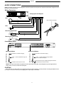
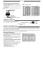
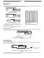
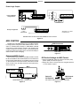
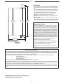
Model P4800 System Processor Installation Guide 2007, Shure Incorporated 27B8695 (Rev. 3) Patent No. 5,999,631 Printed in U.S.A. ENGLISH DESCRIPTION The P4800 System Processor is a 4-input, 8-output digital audio processor. It performs all the necessary functions between the mixers and the power amplifiers in small to medium sized sound systems. Using the P4800’s drag-and-drop Graphical User Interface, processors can be placed anywhere in the signal path. The 4-by-8 matrix mixer allows any or all inputs to be routed to any or all outputs with additional controls for levels and polarity. The P4800 can store up to 128 configurations that can be recalled using simple contact closures, MIDI, or RS232 commands. USING THE P4800 SOFTWARE Instructions for the P4800 software are available in PDF format on the CD-ROM, or on the Shure Internet site at www.shure.com. NOTE: Register this product by filling out and mailing the enclosed registration card, or register online at the Shure World Wide Web site (www.shure.com). Registration enables you to receive information about software updates as they become available. PACKING LIST S S S S Power Cable 5-pin DIN ShureLink Cable 4 Rackmount Screws with Nylon Washers S 2 Block Connector Terminals, 10-pin (for control inputs and outputs) S One P4800 Software and Online User Guide CD–ROM 12 Block Connector Terminals, 3-pin (for audio inputs and outputs) ! IMPORTANT SAFETY INSTRUCTIONS ! 1. 2. 3. 4. 5. 6. 7. 8. 9. READ these instructions. KEEP these instructions. HEED all warnings. FOLLOW all instructions. DO NOT use this apparatus near water. DO NOT expose the apparatus to dripping and splashing. DO NOT put objects filled with liquids, such as vases, on the apparatus. CLEAN ONLY with a dry cloth. DO NOT block any of the ventilation openings. Install in accordance with the manufacturer’s instructions. Do not install near any heat sources such as radiators, heat registers, stoves, or other apparatus (including amplifiers) that produce heat. DO NOT defeat the safety purpose of the grounding-type plug. The third prong is provided for your safety. When the provided plug does not fit into your outlet, consult an electrician for replacement of the obsolete outlet. 10. PROTECT the power cord from being walked on or pinched, particularly at plugs, convenience receptacles, and the point of exit from the apparatus. 11. USE only attachments/accessories specified by the manufacturer. 12. USE only with a cart, stand, tripod, bracket, or table specified by the manufacturer or sold with the apparatus. When a cart is used, use caution when moving the cart-apparatus combination to avoid injury from tip-over. 13. UNPLUG this apparatus during lightning storms or when unused for long periods of time. 14. REFER all servicing to qualified service personnel. Servicing is required when the apparatus has been damaged in any way, such as when the power-supply cord or plug has been damaged, liquid has been spilled or objects have fallen into the apparatus, the apparatus has been exposed to rain or moisture, does not operate normally, or has been dropped. This symbol indicates that there are important operating and maintenance instructions in the literature accompanying this unit. This symbol indicates that dangerous voltage constituting a risk of electric shock is present within this unit. WARNING: Voltages in this equipment are hazardous to life. No user-serviceable parts inside. Refer all servicing to qualified service personnel. The safety certifications do not apply when the operating voltage is changed from the factory setting. 1 ENGLISH REQUIREMENTS Power S 100–240 Vac, 50/60 Hz S 60 W maximum Computer S 20 MB of hard drive space S CD ROM drive S RS–232 or RS–422 serial port S S S 9–pin serial cable for RS–232 or RS–422 VGA monitor with 640 x 480/256 color, or higher resolution Mouse or other pointing device Processor speed and memory requirements vary, depending on the version of Windows and number of background applications you are running. Operating the P4800 software simultaneously with programs such as SIA–Smaart or Gold Line TEFt requires a faster processor and more RAM. The following table lists the minimum requirements for running the P4800 software with no other applications in the background, including virus protection, firewall, instant messaging, or email. Windows Version Processor Speed RAM 95, 95B, and 98 Pentium 166 MHz 32 MB 98, Second Edition Pentium 166 MHz 48 MB NT Pentium 233 MHz 64MB ME Pentium 300 MHz 64 MB 2000 Professional Pentium 300 MHz 96 MB XP Professional, Home Pentium 300 MHz 128 MB MOUNTING S S S Mount the P4800 in any standard 19-inch audio equipment rack using the supplied screws. As with all digital equipment, it is best not to mount wireless equipment directly above or below the P4800. Additional rackmount supports may be necessary for mobile installations in which the unit may undergo extreme vibration or shock. See Figure 17 for complete dimensions. Standard 19” Rackmount Space RACK MOUNTING THE SYSTEM PROCESSOR Figure 1 POWER AND INITIALIZATION Connecting to Power Mains Use the supplied power cable to connect the P4800 System Processor to an active 100–240 Vac power source. The internal power supply adjusts automatically to accommodate any voltage within this range. The power LED on the front panel glows green while power is applied, as shown in Figure 2. NOTE: The P4800 System Processor is intended for continuous operation. Therefore, there is no power on/off switch. Power LED POWER LED Figure 2 Initialization Once power is applied, the P4800 System Processor takes approximately 15 seconds to initialize. While initializing, the LEDs illuminate. The P4800 is ready to use once the LEDs stop flashing. INITIALIZATION Figure 3 2 ENGLISH AUDIO CONNECTIONS NOTE: The P4800 ships with a blank configuration. Audio will not pass from the inputs to the outputs until it has been configured to do so through the computer interface. Wiring Connectors Analog Inputs and Outputs XLR 1 2 2 3 3 Block Connector Terminal 1 RCA T S S T Phone Plug (Balanced) T R S R T S Phone Plug (Unbalanced) T S T S Level Meters/LEDs Input Level Meters Output Level Meters Illuminates at 3 dB below clipping Illuminates at 3 dB below clipping +4 dBu, –10 dBV selectable through software +4 dBu, –10 dBV selectable through software. (Does not reflect 20 dB pad.)* Illuminates when channel is muted. Illuminates when pad is engaged through the software. Illuminates when channel is muted. *NOTE: The output meter reflects the signal level at the output stage of the P4800. The 20 dB pad acts upon the signal after the output stage, so it does not reflect the 20 dB pad. 20 dB Pad Each output has a 20 dB pad that can be engaged through the software interface. Use this pad when connecting the P4800 to lowerlevel inputs. It cannot be used to prevent clipping at the output stage of the P4800. 3 ENGLISH COMPUTER CONNECTIONS RS-232 Connect the COM port on your computer to one of the 9-pin RS-232 connectors on the P4800 device using a male-to-female serial cable, as shown in Figure 4. NOTE: Use only a standard, 9-pin, RS-232 cable wired straight-through. Other types of serial cables that use fewer pins or crossed wires will not work. Front Panel RS-232 Serial Port Rear Panel RS-232 Serial Port RS–232, 9-PIN SERIAL CABLE (MALE-TO-FEMALE) RS-232 SERIAL PORT CONNECTION Figure 4 5 3 1 4 2 1 2 3 4 5 Table 1. RS-232 Pinout P4800 9-PIN FEMALE TO COMPUTER 6 8 6 9 7 1 3 5 2 4 7 8 9 COMPUTER 9-PIN RS-232 MALE CONNECTOR 5 4 3 2 1 9-PIN MALE TO P4800 7 9 6 8 COMPUTER PIN # –– –– TX RX 1 2 RX TX 3 DTR DTR 4 GND GND 5 DSR DSR 6 RTS RTS CTS –– CTS –– 7 8 9 9 7 8 6 P4800 9–PIN RS-232 FEMALE CONNECTOR RS-422 For cable lengths of 50 ft. or more, use an RS-422 serial connection. Unless you have an RS-422 serial port on your computer, you will need an adapter for your computer’s RS-232 COM port, as shown in Figure 5. P4800 RS-422 SERIAL PORT RS-232 SERIAL PORT Table 2. RS-422 Pinout FUNCTION –– RS–232 to RS-422 ADAPTER RS-422 SERIAL PORT CONNECTION Figure 5 PIN # TX– 1 2 RX+ 3 GND 4 –– 5 GND 6 TX+ 7 8 RX– –– 9 Networked Up to 16 ShureLink devices, including P4800s, DP11EQs, DFR11EQs, and UA888s can be linked and controlled from one computer. Connect the ShureLink IN and ShureLink OUT of each device using 5-pin DIN cables (like the one supplied with the P4800), as shown in Figure 6. The last device in the chain must be connected to the first device (the one connected directly to the computer) to form a loop. (Device ID 0) (Device ID 9) (Device ID 12) NETWORKED CONNECTION Figure 6 4 ENGLISH DIP Switch Settings for Networked Devices S Make sure the SHURE LINK/MIDI DIP switch is in the UP position (see Figure 7). S Assign each device a unique Device ID using DIP Switches 1–4 (See Table 3). Table 3. Device ID Settings IMPORTANT: Each device must have a unique Device ID number. ShureLink Activated DIP Switch DIP Switch Device ID 1 2 3 4 Device ID 1 2 3 4 0 DN DN DN DN 8 DN DN DN UP 1 UP DN DN DN 9 UP DN DN UP 2 DN UP DN DN 10 DN UP DN UP 3 UP UP DN DN 11 UP UP DN UP 4 DN DN UP DN 12 DN DN UP UP 5 UP DN UP DN 13 UP DN UP UP 6 DN UP UP DN 14 DN UP UP UP 7 UP UP UP DN 15* UP UP UP UP * Default Device ID DIP Switches DIP SWITCH SETTINGS FOR NETWORKED DEVICES Figure 7 COMMUNICATIONS LED The communications LED illuminates whenever there is activity between the device and the PC. Communications LED COMMUNICATIONS LED Figure 8 CONTROL PIN CONNECTIONS The control pins on the back of the P4800 unit connect to switches, potentiometers, LED indicators, and third-party control hardware. Control Input pins can be used to change presets, adjust gain, and mute channels. Logic Output pins can be used to power LEDs or relays in response to preset changes or muted channels. NOTE: Control pins must be configured to match the attached control hardware using the P4800 software (Refer to the Control Pin section of the online help or the online user guide included on the P4800 CD ROM). Determining Pin Allocations Table 4. Binary Control Pin Allocation You must begin by determining which pins to use for preset control and preset logic output. These pins will connect to external hardware that switches presets or receives logic output about the current preset. Number of Presets 2 4 8 16 32 64 128 Any remaining, unallocated pins can then be used for processor control and processor logic output to adjust gain, mute channels, or power LEDs and relays. The number of pins needed for preset control and preset logic output depends on the type of control hardware and the number of presets. Use the following guidelines: One-to-One: Use one pin for each preset, starting at Pin 1 and proceeding to the right. You must use consecutive pins. Binary: Use the pin numbers as listed in Table 4. Custom Switch: Use Pin 1 for up to 10 presets. Shure Proprietary Switches: DRS10–Use Pin 1 for up to 10 presets. 5 Pin Numbers 1 1 and 2 1–3 1–4 1–5 1–6 1–7 ENGLISH Control Input Pins Preset Control Figure 9 shows examples of how to connect different types of preset control hardware to the Control Input pins. When properly configured, the P4800 changes to the appropriate preset in response to the switch. One-to-one Configuration (Each pin represents one preset) Table 5. Custom Switch Resistor Values Ground Ground Binary Configuration Custom Switch Configuration* PRESET RESISTOR VALUE 1 97 kΩ – ∞ Ω 2 44–60 kΩ 3 26–32 kΩ 4 17–20 kΩ 5 11.3–13.6 kΩ 6 7.8–9.3 kΩ 7 5.2–6.3 kΩ 8 3.3–4.1 kΩ 9 1.9–2.5 kΩ 10 0.63–1.1 kΩ A resistor with a value within the specified range switches the device to the corresponding preset. Ground * See Table 5 for resistor values. A two-conductor, unshielded cable, such as a Belden 8442, is recommended. The total resistance of the cable run must be less than 100 ohms. WIRING CONTROL INPUT PINS FOR PRESET CONTROL Figure 9 Processor Control Figure 10 shows examples of how to connect a potentiometer or a switch to the Control Input pins. The P4800 can then be configured to respond to the switch or potentiometer by changing gain settings or muting channels. 100kW Potentiometer (Audio Taper) Switch (momentary or toggle) Ground WIRING CONTROL INPUT PINS FOR PROCESSOR CONTROL Figure 10 Logic Output Pins Processor Logic Output Figure 11 shows examples of how to wire Logic Output pins to LEDs or relays. You can then configure the P4800 to ground the appropriate pins to reflect muted channels. 5V dc Relay 500Ω Resistor* LED *Necessary for LEDs not rated for 5V. WIRING LOGIC OUTPUT PINS FOR PROCESSOR LOGIC OUTPUT Figure 11 Figure 12 shows examples of how to wire Logic Output pins to LEDs, relays, or third-party logic hardware. You can then configure the P4800 to ground the appropriate pins to reflect the active preset. 6 ENGLISH Preset Logic Output One-to-One/Binary Configurations LEDs 5V dc Relays Binary Configuration 500Ω Resistors* BINARY LOGIC HARDWARE *Necessary for LEDs not rated for 5V. +5V WIRING LOGIC OUTPUT PINS FOR PRESET LOGIC OUTPUT Figure 12 MIDI CONTROL MIDI Connectors The MIDI port on the P4800 allows you to use a MIDI controller to change presets and perform other P4800 functions. For example, a standard MIDI message for PROGRAM CHANGE would cause a preset change in a device. The message must contain the Device ID and the number of the desired preset. Consult the Online User Guide (on the included CD–ROM) for details on MIDI control messaging. MIDI PORT Figure 13 Networked MIDI Control DIP Switch Settings for MIDI Control S Set the SHURELINK / MIDI DIP switch to the down (“DN”) Up to 16 devices can be linked to one MIDI controller. Connect the ShureLink/MIDI IN and ShureLink/MIDI OUT of each device using 5 pin DIN cables (like the one supplied) as shown in Figure 14. The last device in the chain must be connected to the first device to form a loop. The MIDI controller can be placed anywhere in the loop. position (MIDI) as shown in Figure 15. S Assign each device a unique Device ID using DIP switches 1–4 (See Table 3, Page 4). MIDI Controller (Device ID 12) (Device ID 9) Device ID DIP Switches MIDI Control Activated DIP SWITCH SETTING FOR MIDI CONTROL Figure 15 NETWORKED MIDI CONNECTION Figure 14 7 ENGLISH AMX/CRESTRON CONTROL The P4800 uses a standard 7 wire RS–232 port for control. Crestron and AMX controllers use 5 wire RS–232. In order to use a P4800 with Crestron or AMX system, you will need to build a custom cable. Refer to the following diagram for wiring instructions. AMX/CRESTRON END (FEMALE) 5 4 9 3 8 2 1 7 1 6 P4800 CONTROL INPUT P4800 END (MALE) 2 6 3 7 4 5 8 9 1kΩ 1/4 watt CABLE WIRING DIAGRAM FOR AMX/CRESTRON CONTROL Figure 16 For a complete listing of AMX/Crestron control codes, subroutines and library files for the P4800, visit Shure’s website at htttp://shure.custhelp.com. Follow the route listed below to access the Adobe Acrobat document. 1. Go to htttp://shure.custhelp.com. 2. In the “Search Text” field, enter “P4800 RS232” and click the “Search” button. 3. Click on the “P4800 RS232 Codes – AMX / Crestron Subprograms” link in the “Answers” list. 4. Click on “P4800 RS232 Commands and Connection Instructions” to view or download the document. SPECIFICATIONS Furnished Accessories Frequency Response 20 Hz to 20 kHz +1, –3 dB Dynamic Range 100 dB minimum, A-weighted, 20 Hz to 20 kHz Sampling Rate 48 kHz Digital-to-Analog, Analog-to-Digital Conversion 24-bit Impedance Input: 10 kΩ Output: 120 Ω Input Clipping Level +26 dBu minimum Output Clipping Level +22 dBu +2 dBu (with 20 dB pad) Total Harmonic Distortion < 0.05%, +4 dBu, 20 Hz to 20 kHz Propagation Delay from Input to Output <1.5 ms Polarity Input to output: non-inverting (inverting optional) Control Pins Voltage Supply: 5 Vdc, 100 mA (total) Logic Output Current Sinking Ability: 500 mA Operating Voltage 100–240 Vac, 50/60 Hz (auto-switching) Maximum Power Drain 60W Temperature Range Operating: –7_ to 49_ C (20_ to 120_ F) Storage: –29_ to 74_ C (–20_ to 165_ F) Dimensions 19 in x 11 in x 1 3/4 in (See Figure 17) Weight 4.1 kg (9.0 lbs) Packaged Shipping Weight 6.0 kg (13.2 lbs) Power Cable (P4800) . . . . . . . . . . . . . . . . . . . . . . . 95A8389 Power Cable (P4800E) . . . . . . . . . . . . . . . . . . . . . . 95A8247 5-pin DIN Shure Link Cable . . . . . . . . . . . . . . . . . . 95A8676 Hardware Kit . . . . . . . . . . . . . . . . . . . . . . . . . . . . 90AB8100 12 Block Connector Terminals, 3-pin (for audio inputs and outputs) 2 Block Connector Terminals, 10-pin (for control inputs and outputs) 4 Rackmount Screws and Washers Optional Accessories DRS10—Wallplate unit with 10-position rotary switch for preset control Service Information For additional service or parts information, please contact the Shure Service department at 1-847-600-8440. Outside the United States, please contact your authorized Shure Service Center. 8 ENGLISH Certifications 4.76 mm (3/16 IN.) 431.0 mm (16–31/32 IN.) 443.7 mm (17–15/32 IN.) UL Listed and cUL Listed to UL 6500 and CSA E60065. Authorized under Verification provision of FCC Part 15 as a Class B Digital Device. This Class B digital apparatus complies with Canadian ICES–003. Conforms to European Union Directives, eligible to bear CE marking. Meets applicable tests and performance criteria in European Standard EN55103 (1996) parts 1 and 2, for residential (E1) and commercial and light industrial (E2) environments. NOTE: EMC conformance testing is based on the use of supplied and recommended cable types. The use of other cable types may degrade EMC performance. EMC conformance testing is based on the fact that the computer is used for setup purposes only and disconnected during EMC testing. 482.6 mm (19 IN.) Information to User Changes or modifications not expressly approved by Shure Incorporated could void your authority to operate this equipment. This equipment has been tested and found to comply with the limits for a Class B digital device, pursuant to Part 15 of the FCC Rules. These limits are designed to provide reasonable protection against harmful interference in a residential installation. This equipment generates, uses and can radiate radio frequency energy and, if not installed and used in accordance with the instructions, may cause harmful interference to radio communications. However, there is no guarantee that interference will not occur in a particular installation. If this equipment does cause harmful interference to radio or television reception, which can be determined by turning the equipment off and on, the user is encouraged to try to correct the interference by one or more of the following measures: 76.2 mm (3 IN.) 274.6 mm (10-13/16 IN.) Reorient or relocate the receiving antenna. 279.4 mm (11 IN.) Increase the separation between the equipment and receiver. DIMENSIONS Figure 17 Connect the equipment into an outlet on a circuit different from that to which the receiver is connected. Consult the dealer or an experienced radio/TV technician for help. LIMITED ONE-YEAR WARRANTY Shure Incorporated (“Shure”) hereby warrants that this product will be free from defects in materials and workmanship for a period of one year from the date of purchase for all cartridge and housing assembly parts and for a period of one year from the date of purchase for all transmitter parts. At its option Shure will repair or replace the defective product and promptly return it to you, or refund the purchase price. You should retain proof of purchase to validate the purchase date and return it with any warranty claim. If you believe this product is defective within the warranty period, carefully repack the unit, insure it, and return it postage prepaid to: Shure Incorporated Attention: Service Department 222 Hartrey Avenue Evanston, Illinois 60202-3696 U.S.A. Outside the United States, return the product to your dealer or Authorized Service Center. This warranty does not apply in cases of abuse or misuse of the product, use contrary to Shure’s instruction, or unauthorized repair. All implied WARRANTIES OF MERCHANTABILITY or FITNESS FOR A PARTICULAR PURPOSE are hereby disclaimed and Shure hereby disclaims liability for incidental, special, or consequential damages resulting from the use or unavailability of this product. Some states do not allow limitations on how long an implied warranty lasts, or the exclusion or limitation of incidental or consequential damages, so the above limitation may not apply to you. This warranty gives you specific legal rights, and you may have other rights which vary from state to state. Trademark Notices: The stylized Shure logo and the word “Shure” are registered trademarks of Shure Incorporated. Windows is a registered trademark of Microsoft Corporation. 9 SHURE Incorporated http://www.shure.com United States, Canada, Latin America, Caribbean: 5800 W. Touhy Avenue, Niles, IL 60714-4608, U.S.A. Phone: 847-600-2000 U.S. Fax: 847-600-1212 Intl Fax: 847-600-6446 Europe, Middle East, Africa: Shure Europe GmbH, Phone: 49-7131-72140 Fax: 49-7131-721414 Asia, Pacific: Shure Asia Limited, Phone: 852-2893-4290 Fax: 852-2893-4055