1
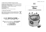
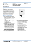
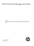
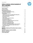
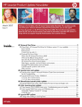
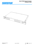
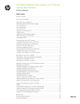
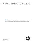
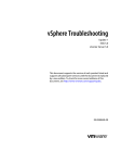
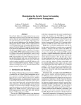
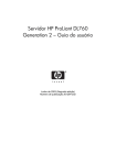
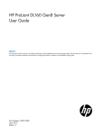
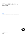
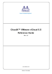
Technical white paper Best practices for deploying VMware vSphere 5 with VMware High Availability and Fault Tolerance on HP LeftHand Multi-Site SAN cluster Table of contents Executive summary 2 Deploying VMware High Availability and VMware Fault Tolerance on HP LeftHand Multi-Site SAN clusters Overview Solution components Hardware and software requirements 2 2 3 5 Deployment best practices Deployment strategy Configuring the HP LeftHand MultiSite SAN 7 7 8 Solution tests Test hardware/software configuration Test storage layout 18 Implementing a proof-of-concept 22 Summary 23 Appendix A: Additional features of HP LeftHand with vSphere 5 Application Managed Snapshots in vSphere Snapshots of Raw Devices Snapshots on VMFS datastores Remote Copy volumes and SRM SmartClone volumes vSphere Metro Storage Cluster (vMSC) using HP LeftHand Multi-Site For more information 18 19 23 23 23 24 24 24 24 25 Executive summary Virtually every business organization understands that successful operations depend on the continuous availability of its applications. Most companies rely on internal applications, ranging from enterprise resource planning to payroll systems, to keep the wheels of their enterprise turning. They also depend on external-facing applications for everything from selling products to automating the supply chain with suppliers and partners. The failure of any of these businesscritical applications could be catastrophic to a company. The causes of downtime are more numerous than most people think. Top-of-mind causes often include fire and natural disasters such as floods, tornadoes, and hurricanes. There are also unexpected causes including power and cooling system failures. Just as serious are the failures that don’t count as a true disaster. A fire in another part of the building can cause smoke and water damage in the most well-protected datacenters. Then there are human errors that affect the datacenter, which can range from the wrong circuit breaker being thrown to an accidental discharge of firesuppression material. In fact, 70% of all unplanned downtime is caused by human error. When a failure occurs, its affect can be as narrow as a single system, or as wide as a room, floor, building, or entire site. A comprehensive business continuity solution should include the capacity to recover operations after a major disaster, as well as the capacity to remain online during minor disruptions. VMware vSphere 5 has brought great relief to IT organizations searching for high availability (HA), fault tolerance (FT) and disaster recovery (DR) solutions by reducing implementation cost and complexity. This best practices white paper describes a cost-effective, simple-to-deploy, easily managed, highly available fault tolerant solution that can be put in place by using an HP LeftHand Multi-Site SAN cluster with VMware vSphere 5. This solution provides zero downtime and zero data loss in the event of failures of servers and/or storage. Complementing VMware vSphere 5 with LeftHand SANs addresses the storage demands and cost pressure associated with server virtualization, data growth, and business continuity. HP LeftHand SANs scale capacity and performance linearly without incurring downtime, enabling it to support small customers to mid-sized enterprises requiring mission-critical applications. Note HP LeftHand was previously referred to as HP P4000. LeftHand operating system was previously referred to as SAN/iQ. Target audience: The white paper is intended for solution architects, engineers, and project managers involved with the deployment of HP LeftHand Multi-Site SAN clusters with VMware vSphere 5 virtualization solutions. It provides recommendations and should not be regarded as a stand-alone reference. The audience should be familiar with the HP LeftHand Multi-Site SAN architecture and virtualized infrastructures. It is expected that the reader will also have a technical background with VMware vSphere 5, especially in VMware High Availability (HA) and VMware Fault Tolerance (FT). In addition, the reader should understand the architecture of VMware vSphere 5 and how this product is able to virtualize hardware resources, as outlined in various in-depth white papers available at http://www.vmware.com/support/pubs/vsphere-esxi-vcenter-server-pubs.html. This white paper describes characterization work performed in January 2012. Deploying VMware High Availability and VMware Fault Tolerance on HP LeftHand Multi-Site SAN clusters Overview The HP and VMware solution described in this white paper discusses the usage of HP LeftHand Multi-Site SAN clusters with VMware Fault Tolerance (FT) and VMware High Availability (HA). The solution gives the ability to stretch a VMware vSphere cluster across two sites and to provide full fault tolerance and built-in zero downtime between the two sites. HP customers have been using the HP LeftHand Multi-Site SAN solution for years with VMware, but typically only with 2 VMware HA. The solution in this paper extends the high availability offered by VMware HA by using a feature called VMware Fault Tolerance, which protects mission-critical virtual machines (VMs) from downtime and data loss. VMware HA provides the ability to migrate VMs to another host and restart the VMs. VMware FT allows two virtual machines to run simultaneously in lockstep through the use of VMware vLockstep technology. When the primary VM fails, the secondary VM immediately takes over and becomes the primary VM, picking up where the failed VM left off. A new secondary VM will then spawn on the next available ESXi host. Figure 1 shows an example of VMware FT transparent failover. While VMware FT and HA provide tremendous resiliency for VMs, if the underlying storage fails it can take down the environment. HP LeftHand Multi-Site SAN clusters extend the protection down to storage, just as the two VMware features protect the hosts and the virtual machines. By combining the three capabilities – VMware FT, VMware HA and HP LeftHand Multi-Site SAN cluster – an entire site in one location is protected by a secondary site and vice versa. Figure 1. VMware FT – Transparent Failover HP developed a test plan to demonstrate VMware FT and VMware HA functioning in a multi-site environment with the Multi-Site SAN. The objective is to demonstrate business continuity with zero downtime in the event of a failure that takes one site offline. A multi-site single cluster configuration can be split across 2 logical or physical sites. “One site” can be a single server/storage configuration in a rack, a server/storage configuration in a separate room, or an entire physical site. Solution components HP LeftHand Multi-Site SAN cluster with VMware HA clusters VMware ESXi hosts can be placed into groups called clusters. A cluster contains 2 to 32 hosts that work together to enable features such as VMware HA and VMware Distributed Resource Scheduler (DRS). All the VMs in an HA cluster are protected by VMware HA, which detects failures of ESXi hosts. When a host fails, VMware HA moves virtual machines from a failed host and restarts them on another unaffected host within the cluster. Shared storage is an important component of the solution. Since the storage array generally stores the virtual disks of the VMs, even the smallest disruption can negatively affect an environment where availability is critical. HP LeftHand Network RAID stripes and mirrors multiple copies of data across a cluster of storage nodes, eliminating any single point of failure in the SAN. Applications have continuous data availability in the event of a power, network, disk, controller, or entire storage node failure. HP LeftHand HA storage clusters provide highly available shared storage for VMware vSphere environments. In the best practices assessment conducted, two P4800s were used. Each HP P4800 consists of two storage nodes and one MDS600 disk enclosure. The P4800s were spread across two separate racks: each rack contained one node from each P4800 and one MDS600 disk enclosure. Each storage node was configured with network-interfaces-(NIC)-teamed RAID level support, and also Network RAID for Multi-Site SAN cluster configuration. The storage nodes operate independently during normal operation hours. Each storage node has the ability to simultaneously provide server iSCSI LUNs for VMware Virtual Machine File System (VMFS) datastores or Raw Device Mappings (RDM). When a controller fails on one of the nodes, data services are transferred from the failing controller to the surviving controller. This happens without a disruption in service. A controller failure does not adversely affect an ESXi host or the VMs on the host. Network RAID provides additional resiliency for the LeftHand SAN by adding synchronous replication on a volume-byvolume basis. This protection is provided in addition to RAID at disk level, thereby allowing for better overall protection. Network RAID is synchronous replication or mirroring of data for a volume across all storage nodes in the cluster. Network RAID 10 or higher is required to replicate data in a Multi-Site SAN environment. In order to prevent impacting 3 disk I/O to the ESXi hosts, the round-trip latency between the sites must be no more than 2 milliseconds. Multi-Site SAN clusters can maintain a low latency across long distances without compromising data. For high availability, there must be protection against failures of components such as servers, storage arrays or nodes, and networks. Protection against site-wide failures such as electrical and cooling is also necessary. VMware vSphere 5 does this by creating virtual machines that are set up to failover to other servers or another site in the event of a sitewide failure. The HP LeftHand Multi-Site SAN cluster does the same for storage. With the HP Centralized Management Console (CMC), create a multi-site cluster of storage nodes spread out across two locations that act together as one logical SAN, but can accommodate a component failure or site-wide failure and keep the data volumes up and available. If a site failure occurs, the VMs containing the applications are restarted on another ESXi host at the other site. So as soon as they reboot, the VMs will locate their data volumes on the Multi-Site SAN and continue to operate. The application and user will see minimal interruption. Figure 2 shows a diagram of the hardware that was utilized for this characterization effort. Figure 2. Hardware utilized in test configuration ProCurve ProCurve HP ProCurve Mode 3 5 7 9 11 Link 13 Mode 15 17 19 21T 23 T Link 21s Mode 23s 2 Mode 4 6 8 10 12 Link 14 Mode 16 18 20 22T 24 T Link 22s Mode 24s Usr Clear Console Auxiliary Port HP ProCurve * Spd Mode: Off = 10 Mbps, Flash = 100 Mbps, On = 1 or 10Gbps 10/100/1000Base-T Ports ( 1 - 24T ) – Ports are Auto-MDIX 6600-24G Switch ProCurve Link 1 Mode 3 5 7 9 11 Link 13 Mode 15 17 19 21T 23 T Link 21s Mode 23s Link 2 Mode 4 6 8 10 12 Link 14 Mode 16 18 20 22T 24 T Link 22s Mode 24s J9263A Networking by HP Power PS Tmp Fault Act LED Mode Fan FDx Spd * Test Locator Usr Status Reset Clear Console Auxiliary Port HP network switch HP ProLiant BL460c G7 UID HP ProLiant BL460c G7 UID ProCurve Networking by HP HP network switch HP StorageWorks P4000sb G2 HP ProLiant BL460c G7 UID Use only one (T or S) for each Port 1 Link FDx Spd * Reset Dual-Personality Ports: 10/100/1000-T (T) or SFP (S) Link Act LED Mode Fan Test Status Use only one (T or S) for each Port PS Tmp Fault Dual-Personality Ports: 10/100/1000-T (T) or SFP (S) * Spd Mode: Off = 10 Mbps, Flash = 100 Mbps, On = 1 or 10Gbps 10/100/1000Base-T Ports ( 1 - 24T ) – Ports are Auto-MDIX 6600-24G Switch J9263A Power Locator HP StorageWorks P4000sb G2 UID HP ProLiant BL460c G7 UID UID HP ProLiant BL460c G7 HP StorageWorks P4000sb G2 HP ProLiant BL460c G7 UID UID HP StorageWorks P4000sb G2 UID UID FLEX 1 FLEX 1 FLEX 1 FLEX 1 FLEX 1 FLEX 1 FLEX 1 FLEX 1 FLEX 1 FLEX 1 FLEX 2 FLEX 2 FLEX 2 FLEX 2 FLEX 2 FLEX 2 FLEX 2 FLEX 2 FLEX 2 FLEX 2 AD/ DNS MS Exchange M vSphere FT VM Secondary M vSphere FT VM Primary MS Exchange AD/ DNS OK OK c7000 with 3 BL460c G7 and 2 HP P4800 storage blades c7000 with 3 BL460c G7 and 2 HP P4800 storage blades HP StorageWorks MDS600 8 15 22 29 2 9 16 23 30 3 10 17 24 31 4 11 18 25 32 5 12 19 26 33 6 13 20 27 34 7 14 21 28 35 1 8 15 22 29 2 9 16 23 30 3 10 17 24 31 4 11 18 25 32 5 12 19 26 33 6 13 20 27 34 7 14 21 28 35 1 UID HP P4800 storage Site A HP StorageWorks MDS600 8 15 22 29 2 9 16 23 30 3 10 17 24 31 4 11 18 25 32 5 12 19 26 33 6 13 20 27 34 7 14 21 28 35 1 UID HP LeftHand Multi-Site Cluster vSphere 5 Cluster 8 15 22 29 2 9 16 23 30 3 10 17 24 31 4 11 18 25 32 5 12 19 26 33 6 13 20 27 34 7 14 21 28 35 1 UID UID HP P4800 storage Site B Incorporating VMware FT VMware extends their high availability capability with the addition of VMware FT. With VMware HA, all VMs in the HA cluster are protected from server failure by being restarted on another healthy ESXi host within the same cluster. Using VMware FT, all the FT-enabled VMs in the HA cluster experience no data loss and no service interruption in the event of a host failure. Of course the other VMs in the HA cluster are still protected by VMware HA, but will experience a disruption of service as they are restarted elsewhere in the cluster. VMware FT provides continuous availability by running two identical VMs on two separate ESXi hosts. Continuous availability of the VM is ensured when protecting VMs with VMware FT for hardware or component failures. With MultiSite SANs, even entire site-wide failures are protected. When the primary VM goes down due to an ESXi host failure or an entire site failure, the secondary VM immediately takes over, without interruption or data loss, and starts communicating with the outside world. The secondary VM now becomes the primary protected VMware FT VM while residing on a separate host in the same vSphere cluster. It is important to emphasize that during a component or site 4 failure, there is no failover activity in the SAN. A failover to the other SAN or mirrored volume is not necessary. The data volumes continue to exist due to network RAID, and no action is required on the part of the SAN administrator. Note While Multi-Site SANs do not require action after a site-failure, VMware FT does. During a site-wide failure, VMware FT will create new secondary VMs on one of the remaining hosts. After the original site comes back up, a VMware administrator will need to migrate the newly created secondary FT VMs back to the original site non-disruptively using vMotion. This is required to prevent both the primary and secondary VMs from residing on the same site. Hardware and software requirements There are numerous requirements to consider when configuring the solution discussed in this white paper. The following sections cover the areas that need attention in planning and deployment. VMware has written a document covering VMware FT and VMware HA configuration, as well as best practices specific to these features. The guide is located at http://pubs.vmware.com/vsphere-50/topic/com.vmware.ICbase/PDF/vsphere-esxi-vcenter-server-50-availabilityguide.pdf. HP suggests testing your proof-of-concept before deploying the solution. HP hardware With respect to the hardware used for the solution, this document will discuss HP c-Class server blades, LeftHand storage nodes and HP Networking. In addition, HP has also written documents describing the Multi-Site SAN solution, which explain the best practices for LeftHand storage nodes for VMware vSphere: “HP P4000 Multi Site HA/DR Solution Pack User Guide” http://bizsupport2.austin.hp.com/bc/docs/support/SupportManual/c03041871/c03041871.pdf “HP P4000 LeftHand SAN Solutions with VMware vSphere Best Practices” http://h20195.www2.hp.com/V2/GetDocument.aspx?docname=4AA3-6918ENW HP c-Class blades It is important to have identical server environments at the two sites. For example, if Datacenter A has a c7000 enclosure with four ProLiant BL460c G7 servers, the secondary site for Datacenter B must utilize the same enclosure and server models. This also means the firmware versions for HP Virtual Connect modules, Onboard Administrator (OA), and server BIOS between sites must be the same. It is also important to maintain configuration consistency between the two sites. For example, server profiles that are used in Datacenter A should be the same for Datacenter B. This will make it easier to configure and install VMware vSphere, VMware FT, and VMware HA. HP Networking Networking is a critical component of the overall solution. Bandwidth and latency are significant considerations in the deployment of the solution described in this white paper. Both VMware FT and HP LeftHand Multi-Site SAN solutions have minimum latency requirements. HP LeftHand Multi-Site SAN clusters require less than 2ms round trip. VMware FT, however, generally requires 1ms round trip latencies. As such, the solution outlined requires less than 1ms round trip latencies. VMware and HP recommend isolating the traffic for VMware FT logging. It is also recommended to use separate VLANs for the network settings of ESXi hosts. Dual redundant network paths are an ideal solution to achieve the redundancy. This will require two NICs each for vMotion, VMware FT logging, iSCSI, VM, and the host Service/Management Console. VMware FT logging traffic can be shared with the vMotion network, but it is not recommended. When a network port becomes saturated, excess frames can be dropped because the port cannot handle the amount of network traffic received. Packets will need to be resent, causing a decrease in performance. Flow control eliminates this problem by controlling the speed at which data is sent to the port. For the iSCSI network ports, enabling Flow Control (supported by HP networking and Virtual Connect) at the physical switch is recommended by both HP and VMware. As a best practice with LeftHand storage nodes, a minimum of two 1GbE NICs, or preferably 10GbE NICs, are recommended. Since the HP LeftHand storage nodes come with two built-in network ports on the system board, adding two more NICs to the PCI bus can help with networking redundancy. 5 HP best practices recommend implementing rapid spanning tree and deploying layer 2 switching. For detailed information, see the document “HP P4000 SAN networking recommendations” at: http://h20195.www2.hp.com/V2/GetDocument.aspx?docname=4AA2-5615ENW LeftHand storage nodes The LeftHand software provides the ability to create and manage multi-site clusters. The Centralized Management Console (CMC) is the mechanism to manage one or more HP LeftHand Multi-Site SANs from a single console. LeftHand storage nodes use virtual IP addresses. An additional IP address can also be assigned to each network interface on the node. In the case of Adaptive Load Balancing (ALB), each node has a unique IP address (regardless of bonding type) and an additional Virtual IP (VIP) address per cluster. HP recommends using a single IP address with ALB and configuring one Virtual IP address per cluster. The virtual IP address will be the target IP address that the ESXi host will use in order to mount the provisioned LUNs. A virtual IP address is a highly available address assigned to a storage cluster. In the event that a storage node in a cluster becomes unavailable, servers can still access volumes through other storage nodes in the cluster using a virtual IP address. The VMkernel network for iSCSI should be placed in a separate VLAN than the management and virtual networks used by virtual machines. If enough networks are available, vMotion and VMware FT should also use separate VLANs. Separating networks by functionality (for example, iSCSI, vMotion, VMware FT, virtual machines) provides higher reliability and improved performance of the individual functions. Infrastructure When working with VMware HA, it is recommended to have at least three hosts to allow for business continuity in the event of a host failure. It is also highly recommended that the cluster be architected so no more than four hosts in a given cluster are located in the same server rack or blade enclosure. For storage, the recommendation is to include at least three sites in the plan (where a site may be a rack, a room or a separate building): two sites for the storage nodes and a third site for the Failover Manager (FOM). The FOM is a virtual appliance that manages quorum of the storage nodes in the event of a loss of network connectivity between the two sites. Note While it is possible to only use two sites with the built-in Virtual Manager, this solution is not recommended, as it requires a manual process for recovering quorum. The Failover Manager is required to achieve transparent failover and it is the recommended solution. Microsoft® Active Directory (AD) and Domain Name Server (DNS) were used in the project to validate the solution. Licensing In order to deploy the solution, the appropriate VMware vSphere licenses will need to be acquired. At the time of this writing, VMware FT, VMware HA and vMotion are part of the VMware vSphere Advanced, Enterprise, and Enterprise Plus licensing. For VMware-HA-only implementations, this can be done with VMware Essentials Plus, Standard, Advanced, Enterprise, or Enterprise Plus since they all include VMware HA functionality. However, for the complete solution, licenses for VMware FT, VMware HA, and vMotion are required. VMware HA VMware HA is a feature that monitors the health of ESXi hosts in a VMware HA cluster. In the event of a host failure due to either planned or unplanned downtime, the virtual machines that were running on the host are moved to another host in the VMware HA cluster and restarted. With vSphere 5.0, all dependencies on DNS for HA have been removed. However, it is always a best practice to ensure all hosts can be resolved properly through DNS. VMware Fault Tolerance VMware FT also has requirements that must be addressed. A few examples include CPU, network latency, and shared storage requirements. For complete details, please refer to the “Best Practices for Fault Tolerance” section of the “vSphere Availability” documentation located at: http://pubs.vmware.com/vsphere-50/topic/com.vmware.ICbase/PDF/vsphere-esxi-vcenter-server-50-availabilityguide.pdf 6 In most cases, customers already have HP Multi-Site clusters running in their environments, which makes enabling Fault Tolerance a simple one step process. Note that VMware DRS may be used to load balance VMware FT VMs in a DRS-enabled cluster, when Enhanced vMotion Compatibility (EVC) is enabled and DRS is set to fully automated mode. If EVC is disabled, VMware FT VMs will not be moved for load-balancing purposes. EVC can be enabled in the cluster settings within VMware vSphere. For further information, please see the “Using Fault Tolerance with DRS” section of the “vSphere Availability” document listed above. Solution requirements For the purposes of this document, HP implemented the best practices for both VMware FT and LeftHand Multi-Site SAN. Having a good understanding of how to configure LeftHand managers is a must. A collection of one or more storage systems can be defined as a management group. Each management group serves as a container for clustering storage systems and creating volumes for storage. LeftHand managers govern the activity of all the storage systems within a management group. If the network infrastructure encounters unplanned downtime, a Multi-Site SAN cluster implementation must protect the SAN in case of a split-brain network scenario. A Failover Manager (FOM) handles automated data failover. It is designed to run as a virtual appliance in a vSphere environment. The FOM participates in the management groups as a real manager in the system for quorum operations only. When using a FOM, configure an equal number of LeftHand managers on both sides of the Multi-Site SAN, and add a FOM at the third location. If an event disables any of the three locations, a quorum will still exist with the managers running at the two remaining locations and automatic failover will occur, allowing the volumes to stay online. As a best practice in a cluster that spans multiple sites, run the same number of managers in each site. In a cluster that spans two sites, run a FOM in a third site, either physical or logical. For more information, please refer to the “HP P4000 Multi-Site HA/DR Solution Pack User Guide” at: http://bizsupport2.austin.hp.com/bc/docs/support/SupportManual/c03041871/c03041871.pdf Deployment best practices Deployment strategy VMware HA designates hosts for particular roles and responds to problems as they arise. In a VMware HA deployment, a set of ESXi hosts is combined into a cluster with a shared pool of resources. Hosts in the cluster are monitored, and if one of the hosts fails, virtual machines that were running on the failed host are restarted on a different host. In addition, VMs are monitored to detect failures, and they are restarted on the same host if this occurs. VMware FT is designed to handle host failures with no downtime for VMs and no loss of data or network connections. It works by creating an identical copy of a virtual machine. One copy of the virtual machine – called the Primary VM – is in the active state, receiving requests, serving information, and running applications. Another copy – called the Secondary VM – receives the same input that is received by the Primary VM, but does not perform any disk writes or network outputs. Any action performed on the Primary VM is recorded and replayed on the Secondary VM, ensuring the two virtual machines stay in lockstep synchronization. In this deployment strategy, VMware FT provides preservation of runtime state and the elimination of application downtime. There are other deployment considerations to keep in mind. Certain infrastructure applications such as Active Directory and DNS are important and can impact deployment if not taken into consideration. For example, if there is a Microsoft Exchange Server VM deployed, it needs to have access to the AD server for authentication reasons. If the Exchange server were to fail, its secondary VM will become the primary VM, but it will still need to access the AD server to authenticate the users. If the network is totally lost, the solution will not work. 7 Configuring the HP LeftHand Multi-Site SAN HP LeftHand Multi-Site SAN The Multi-Site SAN feature enables the synchronous mirroring of data between sites automatically by configuring equal numbers of storage nodes in each site. For a cluster that spans multiple sites, the best practice is to run the same number of managers on each site. For two site clusters, run a Failover Manager on a third site, which can be located on a physical or logical server that is not included in the cluster. For more information on using LeftHand SANs with VMware vSphere 5, please see: http://h20195.www2.hp.com/V2/GetDocument.aspx?docname=4AA3-6918ENW. LeftHand SAN allows for quick and easy configuration through the Centralized Management Console. With the Getting Started Launchpad, a user can quickly discover systems, assign volumes to servers, and create items such as management groups, clusters, and volumes. To create a multi-site SAN, at least two storage systems must be in the Available Systems pool before starting. Figure 3. Centralized Management Console system discovery 8 The first step in creating a multi-site SAN is to create a management group. A management group is a container where storage systems can be clustered and volumes can be created. To create a management group, launch the Management Groups, Clusters, and Volumes Wizard from the Centralized Management Console. Select all the systems to be managed as a group and click Next. The next screen will allow you to create an administrative user if one does not already exist for the targeted systems Figure 4. Management Groups, Clusters, and Volumes Wizard 9 Next, you will be able to select the Network Time Protocol (NTP) and Domain Name Servers (DNS) for the management group. Afterwards, the wizard will prompt the creation of a storage cluster. Select the option for a multi-site cluster and click Next. Select the discovered LeftHand nodes from all sites and the Failover Manager to be part of the cluster. Now the wizard will prompt you to create multiple sites for a cluster. Create one site for each physical site and assign the storage nodes to the sites where they physically reside. The “Make this site primary” checkbox can be selected to determine which site will maintain quorum in the event that the link between sites is lost. This is only used in an environment where no FOM is available. These types of environments are not recommended. Figure 5 shows the creation of a site in the environment. Figure 5. LeftHand cluster Site A The environment in this example has a total of three sites with the third site containing only the Failover Manager. On the next screen you are prompted to create one or more Virtual IPs (VIPs) for the cluster. All clients that will use the SAN will communicate to the cluster using the VIP configured. By using a VIP, the SAN can be expanded, updated, configured, and maintained without the need to disconnect the systems accessing the storage. 10 In order to support a multi-site SAN solution with VMware vSphere 5 FT, at least two iSCSI volumes are needed for a VMware High Availability heartbeat. For each ESXi host to access each volume, you must create the required volumes, define each host in the CMC, and export the volumes to all ESXi hosts. To define a new server, right click the management group from the left navigation and select New Server. Figure 6 shows the new server creation screen. Figure 6. New Server creation Enter the IP address of the VMware vCenter Server as the Controlling Server IP Address. A single subnet with a single Virtual IP (VIP) is recommended for a LeftHand Multi-Site and vSphere 5 environment. Select the option Allow access via iSCSI and enter the Initiator Node Name. The Initiator Node Name can be obtained from vSphere on the Storage Adapters page in the host Configuration tab. As a best practice, only select Enable load balancing if the initiator is compliant. For a list of compliant initiators please see http://h20195.www2.hp.com/V2/GetDocument.aspx?docname=4AA2-5654ENW. As a best practice, assign all servers to sites in the Centralized Management Console. This avoids high-latency connections by connecting servers only to storage systems in the same site when available. After the ESXi hosts have been defined they can be assigned to a site by right-clicking Sites and selecting Edit Site. 11 ESXi hosts can be grouped into server clusters so that volumes can be assigned to the server clusters, not individually. After defining servers, a user may define and assign volumes using the new volume wizard by right clicking the cluster name and selecting New Volume. To use a volume in a VMware HA/FT cluster, it must be assigned with Read/Write permissions to all hosts in the cluster. Clicking the Advanced tab allows you to select a Network RAID level. As a best practice, use either Network RAID-10 or Network RAID-10+2 for a 2 site SAN and RAID-10+1 for a 3-site SAN. Do not use Network RAID-0, Network RAID-5, or Network RAID-6, as they will not tolerate site failures. Network RAID-10+2 offers an even higher level of data protection that enables the Multi-Site SAN to sustain a complete failure at one site and still maintain replicated data at the other site. With Network RAID-10+2 there are four copies of data for the volume on the SAN. Figure 7. Edit Volume 12 VMware Fault Tolerance VMware has released a white paper on VMware FT and VMware HA best practices. One of the best practices is to verify that the HP ProLiant servers are on the VMware hardware compatibility list (HCL) for VMware Fault Tolerance: http://www.vmware.com/resources/compatibility/search.php?deviceCategory=server. Several HP ProLiant servers are on the list, and HP will keep updating the list as more servers become certified. At the time of writing this white paper, HP has several HP ProLiant servers, such as the DL and BL server models, on the list. VMware vSphere 5.0 requires at least two FT compliant servers using the same FT version or host build number. For more information about configuring a VMware FT cluster please see the Fault Tolerance Checklist in the vSphere 5 Availability Guide, available at: http://pubs.vmware.com/vsphere-50/topic/com.vmware.ICbase/PDF/vsphere-esxi-vcenter-server-50-availabilityguide.pdf With many customer instances, one might already have a Multi-Site SAN cluster running VMware HA. Incorporating VMware FT will be the next step for several customers. It will be important to identify which virtual machines will be protected with VMware FT. Enabling the VM for VMware FT is a one-step task to complete. To create a cluster in the vSphere Client, right click on the Datacenter name and select New Cluster. The popup window below shows creating a Cluster called “FT_Site” and selecting “Turn On vSphere HA”, which is required in order to use Fault Tolerance. Also select “Turn on vSphere DRS” in order to support the management, monitoring, placement, and migration of virtual machines with Fault Tolerance turned on. Figure 8. Example of creating a cluster and selecting HA and DRS 13 In preparation for deploying the infrastructure, it will be necessary to work with the network administrator to properly plan for the network traffic. VMware suggests isolating the network traffic for VMware FT logging from virtual machines, iSCSI storage and vMotion. Below is a screenshot of the test setup showing two separate vmnic devices for the main host network, two for a vMotion network, and two for the Fault Tolerant network. This is done in order to provide sufficient network bandwidth for each network and to ensure minimum required response times for the vMotion and FT network requirements. Figure 9. Example of three isolated networks: the general VM network and Management, the vMotion network, and the FT logging network vMotion and VMware FT logging can occur simultaneously on the same network for testing or proof-of-concept purposes, but it is not recommended for production networks due to latency requirements. 14 It should also be noted that the Multi-Site SAN was attached using two additional vmhba ports to further isolate and guarantee sufficient bandwidth for the SAN’s datastore and its required heartbeat datastore. Below is a screenshot of the datastores. Note that the “datastore1(3)” is on a local HP Serial Attached SCSI device of the ESXi host and is used as its own local datastore. It is not used by any of the virtual machines and would not be available for a failover since it is not on a shared device. Datastore “Heartbeat_1” was created on the SAN and used by the VMware HA cluster as the heartbeat storage. The third datastore “Shared Datastore” is used by the various virtual machines for virtual disks that are always to be available to the cluster. Figure 10. Example of the datastores in use After creating a cluster and choosing the cluster options, it is possible to drag and drop hosts into the cluster. Remember that the host servers selected should be FT compliant, with the same FT version or host build number. Additionally, ensure the servers have the same number of cores, memory capacity, and firmware levels so the virtual machines can run successfully on any of the hosts. 15 Also be sure to select “Put all of the host’s virtual machines in the cluster’s root resource pool.” This will ensure that the virtual machine information is always available. Figure 11. Example of designating the location of the resource pool 16 VMware FT can be enabled in the virtual machine menu. Ensure that the secondary VMs created by fault tolerance are placed on an ESXi host in the secondary site. This information can be seen from the Summary tab as show in red in Figure 12. Figure 12. FT virtual machine location 17 When the setup of the cluster is finished, there will be an HA fault tolerant cluster configured with the various hosts, networks, host datastores, and shared datastores. The example in Figure 13 shows four hosts in a cluster called FT_Site, which includes a shared datastore, a heartbeat datastore, an individual non-shared datastore for each of the four hosts, along with the HA and DRS settings. Figure 13. Example of a completed cluster setup Solution tests Test hardware/software configuration Please see the Hardware and software requirements section above for minimum hardware configuration requirements. Hardware The following hardware components were used for this project: Four HP ProLiant BL460c G7 blade servers (vSphere cluster with VMware HA and VMware FT logging) Two HP ProLiant BL460c G7 blade servers as physical hosts for infrastructure Four HP Virtual Connect Ethernet Modules for c-Class BladeSystem Two HP 8212 zl Switches with four 10GbE SR SFP+ transceivers Four HP LeftHand P4800 BladeSystem storage nodes or equivalent LeftHand Multi-Site SAN bundled solution package 18 Software The following software components were used in the project: VMware ESXi 5.0 VMware vCenter Server 5.0 (Primary location on Site B) VMware vSphere Client 5.0 Microsoft Windows® Server 2008 R2 Enterprise Edition HP LeftHand operating system v9.5.00 HP LeftHand Centralized Management Console (CMC) v9.5.00 Figure 14. Hardware utilized in test configuration ProCurve ProCurve HP ProCurve Mode 3 5 7 9 11 Link 13 Mode 15 17 19 21T 23 T Link 21s Mode 23s 2 Mode 4 6 8 10 12 Link 14 Mode 16 18 20 22T 24 T Link 22s Mode 24s Usr Clear Console Auxiliary Port HP ProCurve * Spd Mode: Off = 10 Mbps, Flash = 100 Mbps, On = 1 or 10Gbps 10/100/1000Base-T Ports ( 1 - 24T ) – Ports are Auto-MDIX 6600-24G Switch ProCurve Link 1 Mode 3 5 7 9 11 Link 13 Mode 15 17 19 21T 23 T Link 21s Mode 23s Link 2 Mode 4 6 8 10 12 Link 14 Mode 16 18 20 22T 24 T Link 22s Mode 24s J9263A Networking by HP Power PS Tmp Fault Act LED Mode Fan FDx Spd * Test Locator Usr Status Reset Clear Console Auxiliary Port HP network switch HP ProLiant BL460c G7 UID HP ProLiant BL460c G7 UID ProCurve Networking by HP HP network switch HP StorageWorks P4000sb G2 HP ProLiant BL460c G7 UID Use only one (T or S) for each Port 1 Link FDx Spd * Reset Dual-Personality Ports: 10/100/1000-T (T) or SFP (S) Link Act LED Mode Fan Test Status Use only one (T or S) for each Port PS Tmp Fault Dual-Personality Ports: 10/100/1000-T (T) or SFP (S) * Spd Mode: Off = 10 Mbps, Flash = 100 Mbps, On = 1 or 10Gbps 10/100/1000Base-T Ports ( 1 - 24T ) – Ports are Auto-MDIX 6600-24G Switch J9263A Power Locator HP StorageWorks P4000sb G2 UID HP ProLiant BL460c G7 UID UID HP ProLiant BL460c G7 HP StorageWorks P4000sb G2 HP ProLiant BL460c G7 UID UID HP StorageWorks P4000sb G2 UID UID FLEX 1 FLEX 1 FLEX 1 FLEX 1 FLEX 1 FLEX 1 FLEX 1 FLEX 1 FLEX 1 FLEX 1 FLEX 2 FLEX 2 FLEX 2 FLEX 2 FLEX 2 FLEX 2 FLEX 2 FLEX 2 FLEX 2 FLEX 2 AD/ DNS MS Exchange M vSphere FT VM Secondary M vSphere FT VM Primary MS Exchange AD/ DNS OK OK c7000 with 3 BL460c G7 and 2 HP P4800 storage blades c7000 with 3 BL460c G7 and 2 HP P4800 storage blades HP StorageWorks MDS600 8 15 22 29 2 9 16 23 30 3 10 17 24 31 4 11 18 25 32 5 12 19 26 33 6 13 20 27 34 7 14 21 28 35 1 8 15 22 29 2 9 16 23 30 3 10 17 24 31 4 11 18 25 32 5 12 19 26 33 6 13 20 27 34 7 14 21 28 35 1 UID HP P4800 storage Site A HP StorageWorks MDS600 8 15 22 29 2 9 16 23 30 3 10 17 24 31 4 11 18 25 32 5 12 19 26 33 6 13 20 27 34 7 14 21 28 35 1 UID HP LeftHand Multi-Site Cluster vSphere 5 Cluster 8 15 22 29 2 9 16 23 30 3 10 17 24 31 4 11 18 25 32 5 12 19 26 33 6 13 20 27 34 7 14 21 28 35 1 UID UID HP P4800 storage Site B Test storage layout The Multi-Site SAN products used in the solution were storage nodes with 10Gb Ethernet. HP followed the configuration best practices for the storage nodes, as well as VMware’s best practices for deploying iSCSI shared storage. The storage layout consists of having the storage nodes stretched across two sites. These units were kept within the same lab but configured as separate sites for ease of test management and execution. Both storage nodes had their NICs teamed for ALB. ALB was used because it is the only supported active/active network configuration on the P4800. Network traffic was isolated onto a separate network by creating VLANs to the storage array nodes. Both the CMC console and FOM were configured to have access to both VLANs. This was required for HP engineers to manage the environment. HP performed several tests to validate the configuration. The main tests conducted for this white paper are the loss of ESXi hosts at the primary site, the loss of the storage on either site, and the loss of an entire site. An Outlook client was installed to verify that email could be sent and received at the start and end of each test scenario. 19 The first test consisted of manually powering off ESXi hosts on Blade 1 and Blade 2 on site A with a hard shutdown to simulate power loss. The Primary VMs enabled with VMware FT were running on Blade 1 (AD/DNS) and Blade 2 (MS Exchange), which were the targeted servers to fail. The Secondary VMs were running on Blade 3 (AD/DNS) and Blade 4 (MS Exchange) on site B. Both the Primary and Secondary VMs had access to the same LUN, which was protected by the Multi-Site SAN cluster. Figure 15. Failover tests – ESXi host fails ProCurve ProCurve HP ProCurve Mode 3 5 7 9 11 Link 13 Mode 15 17 19 21T 23 T Link 21s Mode 23s 2 Mode 4 6 8 10 12 Link 14 Mode 16 18 20 22T 24 T Link 22s Mode 24s Usr Clear Console Auxiliary Port HP ProCurve * Spd Mode: Off = 10 Mbps, Flash = 100 Mbps, On = 1 or 10Gbps 10/100/1000Base-T Ports ( 1 - 24T ) – Ports are Auto-MDIX 6600-24G Switch ProCurve Link 1 Mode 3 5 7 9 11 Link 13 Mode 15 17 19 21T 23 T Link 21s Mode 23s Link 2 Mode 4 6 8 10 12 Link 14 Mode 16 18 20 22T 24 T Link 22s Mode 24s J9263A Networking by HP Power PS Tmp Fault Act LED Mode Fan FDx Spd * Test Locator Usr Status Reset Clear Console Auxiliary Port HP network switch HP ProLiant BL460c G7 UID HP ProLiant BL460c G7 UID ProCurve Networking by HP HP network switch HP StorageWorks P4000sb G2 HP ProLiant BL460c G7 UID Use only one (T or S) for each Port 1 Link FDx Spd * Reset Dual-Personality Ports: 10/100/1000-T (T) or SFP (S) Link Act LED Mode Fan Test Status Use only one (T or S) for each Port PS Tmp Fault Dual-Personality Ports: 10/100/1000-T (T) or SFP (S) * Spd Mode: Off = 10 Mbps, Flash = 100 Mbps, On = 1 or 10Gbps 10/100/1000Base-T Ports ( 1 - 24T ) – Ports are Auto-MDIX 6600-24G Switch J9263A Power Locator HP StorageWorks P4000sb G2 UID HP ProLiant BL460c G7 UID UID HP ProLiant BL460c G7 HP StorageWorks P4000sb G2 HP ProLiant BL460c G7 UID UID HP StorageWorks P4000sb G2 UID UID FLEX 1 FLEX 1 FLEX 1 FLEX 1 FLEX 1 FLEX 1 FLEX 1 FLEX 1 FLEX 1 FLEX 1 FLEX 2 FLEX 2 FLEX 2 FLEX 2 FLEX 2 FLEX 2 FLEX 2 FLEX 2 FLEX 2 FLEX 2 AD/ DNS MS Exchange M vSphere FT VM Secondary M vSphere FT VM Primary MS Exchange AD/ DNS OK OK c7000 with 3 BL460c G7 and 2 HP P4800 storage blades c7000 with 3 BL460c G7 and 2 HP P4800 storage blades HP StorageWorks MDS600 8 15 22 29 2 9 16 23 30 3 10 17 24 31 4 11 18 25 32 5 12 19 26 33 6 13 20 27 34 7 14 21 28 35 1 8 15 22 29 2 9 16 23 30 3 10 17 24 31 4 11 18 25 32 5 12 19 26 33 6 13 20 27 34 7 14 21 28 35 1 UID HP P4800 storage Site A HP StorageWorks MDS600 8 15 22 29 2 9 16 23 30 3 10 17 24 31 4 11 18 25 32 5 12 19 26 33 6 13 20 27 34 7 14 21 28 35 1 UID HP LeftHand Multi-Site Cluster vSphere 5 Cluster 8 15 22 29 2 9 16 23 30 3 10 17 24 31 4 11 18 25 32 5 12 19 26 33 6 13 20 27 34 7 14 21 28 35 1 UID UID HP P4800 storage Site B The result when the ESXi hosts on Site A went down due to a power outage was that the Primary VMs running on Blade 1 and Blade 2 were no longer available. The Secondary VMs running on Blade 3 and Blade 4 now became the Primary VMs, and new Secondary VMs were spawned on Blade 3 and Blade 4 on site B. Since there was no disruption to the SAN, the VMs continued running. It is important to note that the VMs must be migrated back to the primary site once it becomes available again. 20 The second test consisted of powering off storage nodes on site A. HP manually powered off the storage nodes on site A. The Primary VMs were running on Blade 1 and Blade 2. The Secondary VMs were running on Blade 3 and Blade 4. Both VMs had access to the same LUN or datastore, which was protected by a Multi-Site cluster. Figure 16. Powering off the storage nodes on Site A ProCurve ProCurve HP ProCurve Mode 3 5 7 9 11 Link 13 Mode 15 17 19 21T 23 T Link 21s Mode 23s 2 Mode 4 6 8 10 12 Link 14 Mode 16 18 20 22T 24 T Link 22s Mode 24s Usr Clear Console Auxiliary Port HP ProCurve * Spd Mode: Off = 10 Mbps, Flash = 100 Mbps, On = 1 or 10Gbps 10/100/1000Base-T Ports ( 1 - 24T ) – Ports are Auto-MDIX 6600-24G Switch ProCurve Link 1 Mode 3 5 7 9 11 Link 13 Mode 15 17 19 21T 23 T Link 21s Mode 23s Link 2 Mode 4 6 8 10 12 Link 14 Mode 16 18 20 22T 24 T Link 22s Mode 24s J9263A Networking by HP Power PS Tmp Fault Act LED Mode Fan FDx Spd * Test Locator Usr Status Reset Clear Console Auxiliary Port HP network switch HP ProLiant BL460c G7 UID HP ProLiant BL460c G7 UID ProCurve Networking by HP HP network switch HP StorageWorks P4000sb G2 HP ProLiant BL460c G7 UID Use only one (T or S) for each Port 1 Link FDx Spd * Reset Dual-Personality Ports: 10/100/1000-T (T) or SFP (S) Link Act LED Mode Fan Test Status Use only one (T or S) for each Port PS Tmp Fault Dual-Personality Ports: 10/100/1000-T (T) or SFP (S) * Spd Mode: Off = 10 Mbps, Flash = 100 Mbps, On = 1 or 10Gbps 10/100/1000Base-T Ports ( 1 - 24T ) – Ports are Auto-MDIX 6600-24G Switch J9263A Power Locator HP StorageWorks P4000sb G2 UID HP ProLiant BL460c G7 UID UID HP ProLiant BL460c G7 HP StorageWorks P4000sb G2 HP ProLiant BL460c G7 UID UID HP StorageWorks P4000sb G2 UID UID FLEX 1 FLEX 1 FLEX 1 FLEX 1 FLEX 1 FLEX 1 FLEX 1 FLEX 1 FLEX 1 FLEX 1 FLEX 2 FLEX 2 FLEX 2 FLEX 2 FLEX 2 FLEX 2 FLEX 2 FLEX 2 FLEX 2 FLEX 2 AD/ DNS MS Exchange M vSphere FT VM Secondary M vSphere FT VM Primary MS Exchange AD/ DNS OK OK c7000 with 3 BL460c G7 and 2 HP P4800 storage blades c7000 with 3 BL460c G7 and 2 HP P4800 storage blades HP StorageWorks MDS600 8 15 22 29 2 9 16 23 30 3 10 17 24 31 4 11 18 25 32 5 12 19 26 33 6 13 20 27 34 7 14 21 28 35 1 8 15 22 29 2 9 16 23 30 3 10 17 24 31 4 11 18 25 32 5 12 19 26 33 6 13 20 27 34 7 14 21 28 35 1 UID HP P4800 storage Site A HP StorageWorks MDS600 8 15 22 29 2 9 16 23 30 3 10 17 24 31 4 11 18 25 32 5 12 19 26 33 6 13 20 27 34 7 14 21 28 35 1 UID HP LeftHand Multi-Site Cluster vSphere 5 Cluster 8 15 22 29 2 9 16 23 30 3 10 17 24 31 4 11 18 25 32 5 12 19 26 33 6 13 20 27 34 7 14 21 28 35 1 UID UID HP P4800 storage Site B The result demonstrates that even when power to the storage nodes was cut abruptly, the virtual machines continue running. In this case the Failover Manager kept quorum and noticed that storage on the primary site was no longer available. Site B storage nodes were still in operation and processing I/Os to the VMs on site A. The CMC console reported the storage nodes being offline for site A. Site B storage nodes performed in a degraded mode due to the lost storage nodes. 21 The third test consisted of powering off the entire blade enclosure including the storage nodes on site A. The Primary VMs were running on Blade 1 and Blade 2. The Secondary VMs were running on Blade 3 and Blade 4. HP abruptly powered off the entire site A to simulate a total loss. Since the test configuration was running AD/DNS services on Blade 1 and MS Exchange on Blade 2 in site A, HP replicated a total site failure including the storage nodes. The result when the entire site went down was that the primary VMs running on Blade 1 and Blade 2 were no longer available. The Secondary VMs running on Blade 3 and Blade 4 now became the Primary VMs, and new Secondary VMs were spawned on Blade 3 and Blade 4 on site B. The applications experienced no downtime during the failure of an entire site. Figure 17. Site A failure ProCurve ProCurve HP ProCurve Mode 3 5 7 9 11 Link 13 Mode 15 17 19 21T 23 T Link 21s Mode 23s 2 Mode 4 6 8 10 12 Link 14 Mode 16 18 20 22T 24 T Link 22s Mode 24s Usr Clear Console Auxiliary Port HP ProCurve * Spd Mode: Off = 10 Mbps, Flash = 100 Mbps, On = 1 or 10Gbps 10/100/1000Base-T Ports ( 1 - 24T ) – Ports are Auto-MDIX 6600-24G Switch ProCurve Link 1 Mode 3 5 7 9 11 Link 13 Mode 15 17 19 21T 23 T Link 21s Mode 23s Link 2 Mode 4 6 8 10 12 Link 14 Mode 16 18 20 22T 24 T Link 22s Mode 24s J9263A Networking by HP Power PS Tmp Fault Act LED Mode Fan FDx Spd * Test Locator Usr Status Reset Clear Console Auxiliary Port HP network switch HP ProLiant BL460c G7 HP ProLiant BL460c G7 ProCurve Networking by HP HP network switch HP StorageWorks P4000sb G2 HP ProLiant BL460c G7 Use only one (T or S) for each Port 1 Link FDx Spd * Reset Dual-Personality Ports: 10/100/1000-T (T) or SFP (S) Link Act LED Mode Fan Test Status Use only one (T or S) for each Port PS Tmp Fault Dual-Personality Ports: 10/100/1000-T (T) or SFP (S) * Spd Mode: Off = 10 Mbps, Flash = 100 Mbps, On = 1 or 10Gbps 10/100/1000Base-T Ports ( 1 - 24T ) – Ports are Auto-MDIX 6600-24G Switch J9263A Power Locator HP StorageWorks P4000sb G2 HP ProLiant BL460c G7 HP ProLiant BL460c G7 HP StorageWorks P4000sb G2 HP ProLiant BL460c G7 HP StorageWorks P4000sb G2 UID UID UID UID UID UID UID UID UID UID FLEX 1 FLEX 1 FLEX 1 FLEX 1 FLEX 1 FLEX 1 FLEX 1 FLEX 1 FLEX 1 FLEX 1 FLEX 2 FLEX 2 FLEX 2 FLEX 2 FLEX 2 FLEX 2 FLEX 2 FLEX 2 FLEX 2 FLEX 2 AD/ DNS MS Exchange M vSphere FT VM Secondary M vSphere FT VM Primary MS Exchange AD/ DNS OK OK c7000 with 3 BL460c G7 and 2 HP P4800 storage blades c7000 with 3 BL460c G7 and 2 HP P4800 storage blades HP StorageWorks MDS600 8 15 22 29 2 9 16 23 30 3 10 17 24 31 4 11 18 25 32 5 12 19 26 33 6 13 20 27 34 7 14 21 28 35 1 8 15 22 29 2 9 16 23 30 3 10 17 24 31 4 11 18 25 32 5 12 19 26 33 6 13 20 27 34 7 14 21 28 35 1 UID HP P4800 storage HP StorageWorks MDS600 8 15 22 29 2 9 16 23 30 3 10 17 24 31 4 11 18 25 32 5 12 19 26 33 6 13 20 27 34 7 14 21 28 35 1 UID HP LeftHand Multi-Site Cluster vSphere 5 Cluster Site A 8 15 22 29 2 9 16 23 30 3 10 17 24 31 4 11 18 25 32 5 12 19 26 33 6 13 20 27 34 7 14 21 28 35 1 UID UID HP P4800 storage Site B In all three cases described, when HP powered on the c7000 enclosure, or powered on the storage node, the action brought an entire site back up. Once power was restored everything continued to function with site B as the primary site. It is important to note that once site A is powered back on; one set of VMs (either primary or secondary) must be manually migrated back to the primary site to establish fault tolerance again. Implementing a proof-of-concept As a matter of best practice for all deployments, HP recommends implementing a proof-of-concept using a test environment that matches the planned production environment as closely as possible. In this way, appropriate configuration and solution deployment can be obtained. For help with a proof-of-concept and to ensure your configuration is supported, contact an HP Services representative or your HP partner (http://www.hp.com/large/contact/enterprise/index.html) 22 Summary In summary, an HP LeftHand SAN solution offers simple management and cost effective high availability. HP LeftHand SANs are built on a clustered storage architecture that eliminates any single point of failure and provides always-online volumes for VMware HA and FT in the event of a variety of failure scenarios. This solution is a highly available IT infrastructure that is simple to implement and manage. Appendix A: Additional features of HP LeftHand with vSphere 5 LeftHand SANs along with VMware vSphere 5 provide an excellent solution to improve your hardware utilization and system availability. LeftHand SANs optimize and protect your storage while vSphere optimizes and protects your computing resources. Together LeftHand and vSphere clusters provide a complete multi-site failover and failback solution. LeftHand Multi-Site SANs protect replicated data between sites: Clusters are geographically aware and use that to optimize the data path Clusters can traverse multiple subnets 4-way replication can keep data redundant even after a complete site failure LeftHand Failover Manager fully automates failover operations vSphere can be used to protect virtual machines across sites: One management interface for server configuration and clustering Makes vMotion, DRS, and HA possible between two “sites” Failover and failback can be automated and controlled by policies Application Managed Snapshots in vSphere HP LeftHand operating system v9.5 expands Application Integration functionality to include vSphere integrated snapshots. This new Application Aware Snapshot Manager enables vSphere volume SAN based snapshots, thereby creating application consistent, point in time copies for reliable recovery of VM states. Without this integration option, snapshots previously were a volume of the LeftHand SAN state. In flight cached data may not have been fully quiesced creating an application recovery point. Now, full data recovery does not depend upon a paused or stopped VM state and flushed data to the SAN. The configuration of the Application Aware Snapshot Manager is performed within the CMC. Users configure the IP address of the Virtual Center server. The Centralized Management Console communicates with the vSphere vCenter Server(s) during the snapshot process. vCenter Server quiesces VMs and takes a vSphere snapshot. VMware Tools within each guest VM quiesces applications. Once quiesced, the SAN performs a hardware based snapshot which contains vSphere VM snapshots when examined through snapshot manager and represented to vSphere hosts. Snapshots of Raw Devices LeftHand SAN snapshots of vSphere 5 Raw Device Mappings (RDMs) are supported in exactly the same way as for physical servers, either booting from the SAN or accessing LUNs on the SAN. Detailed information about LeftHand snapshots and how they work for specific applications is available on the HP website at http://www.hp.com/go/lefthand. In vSphere 5, two compatibility modes for RDMs are available. Virtual compatibility mode allows an RDM to act exactly like a virtual disk file, including the use of vSphere based snapshots. Physical compatibility mode allows direct access of the LUN device for applications that need lower level direct raw device control. RDMs offer some benefits including: Dynamic Name Resolution – the identification associates each RDM with the device regardless of physical server changes, adapter hardware, path changes or device relocation. Distributed File Locking – RDMs are available as shared raw LUNs without losing data across multiple vSphere hosts accessing the same LUN. 23 Snapshots – VM snapshots are possible on RDM LUNs in virtual compatibility mode. Combined with the LeftHand Application Managed snapshots, raw devices may be quiesced in context VMs. Note that this is NOT supported with physical compatibility mode RDMs. Snapshots on VMFS datastores LeftHand SAN snapshots are very useful in a vSphere 5 environment. All virtual machines stored on a single volume can be snap shot and rolled back to at any time. Moreover, snapshots can be mounted to any vSphere 5 host without interrupting access to their source volume. This may be used for data mining or testing real world data without affecting live corporate data. Remote Copy volumes and SRM Remote Copy replicates LeftHand snapshots over WAN links to remote sites for disaster recovery or backup. VMware vSphere 5 environments can be protected by Remote Copy volumes on a scheduled basis and automated by VMware vCenter Site Recovery Manager (SRM) for a simple and complete disaster recovery solution. HP provides a Storage Replication Adapter (SRA) for Site Recovery Manager (SRM) to integrate Remote Copy volumes seamlessly with a vSphere 5 environment. For more information on Remote Copy volumes, review the Remote Copy User Manual installed with the CMC. vSphere 5 and Site Recovery Manager 5 require LeftHand OS v9.5 Application Integration Solution Pack. An option for SRA for SRM 5 must be selected for vSphere 5 and Site Recovery Manager 5 support. The previous version supported SRM 4.1 in a single installer option. LeftHand OS v9.5 supports SRM 1.x/4.x or SRM 5. A best practice is to ensure that LeftHand hardware and software are always up to date. Note that automated failback is now supported as part of the SRM 5 features. SmartClone volumes LeftHand SmartClone volumes may also be used in a vSphere 5 environment. Using HP LeftHand SmartClone technology, all the virtual machines stored on a single volume can be cloned instantly without replicating data. SmartClone volumes consume space for data changes only from the time the SmartClone volume was created. SmartClone volumes are the best way to deploy small quantities of cloned golden image VMs or virtual desktops. Manageability and deployment of Virtual Desktop Infrastructure (VDI) environments are best to leverage VMware View implementations with Linked Clones. Please refer to the HP VDI Reference Architectures at: http://h18013.www1.hp.com/products/servers/vdi/. SmartClone volumes can be used seamlessly with other LeftHand software features, including snapshots or Remote Copy. SmartClone volumes are also very useful for performing tests on virtual machines by quickly reproducing them, without actually using space on the SAN to copy them. Unlike snapshots, delta data is persisted between each source snapshot. Note that every write (including a delete) is a delta block persisted in the SmartClone delta space. If long term space efficiency is required with SmartClone volumes, minimizing writes to the SmartClone datastores include avoiding defragmentation within the guest VM. Successful approaches have also included separation of User and Application data including file redirection. Space reclamation can only be performed with a SmartClone volume by creating a new one retaining the original small source reference with minimal delta data. By removing OS dependence in separation from the User and Applications, periodic SmartClone deletion and re-creation ensures that data delta growth is minimized. Without these approaches, SmartClone volumes may eventually occupy an entire SmartClone’s volume space as delta change data. SmartClone’s initial value is in immediate cloning of golden image volumes. Efficient space utilization objectives need to understand use and mitigation approaches to maximize success. vSphere Metro Storage Cluster (vMSC) using HP LeftHand Multi-Site vSphere Metro Storage Cluster (vMSC) vSphere Metro Storage Cluster (vMSC) is a new VMware certified configuration for stretched storage cluster configurations. A vMSC configuration is designed to maintain data availability beyond a single physical or logical site. A storage device configured in the MSC configuration is supported after successful vMSC certification. All supported storage devices are listed in the VMware Storage Compatibility Guide. HP LeftHand Multi-Site HP LeftHand Multi-Site is a feature of the LeftHand operating system. This technology allows for storage clusters to be stretched across sites to provide high availability beyond failure domains defined by the administrator. Traditionally in Metro Storage Cluster configurations, these failure domains are distinct geographic locations, but the technology can be 24 used to protect against the failure of a logical site that may be a rack, room, or floor in the same building as well as buildings within a campus or datacenters that are separated by as much as 100km or more. The Multi-Site feature is part of the all-inclusive LeftHand feature set and does not require any special licensing. The HP LeftHand Multi-Site solution uses LeftHand OS Network RAID technology to stripe two copies of data across a storage cluster. When deployed in a Multi-Site configuration, LeftHand OS ensures that a full copy of the data resides on site, or each side of the cluster. In Multi-Site/vMSC configurations, data remains available in the event of a site failure or loss of link between sites. A VMware HA/DRS cluster is created across the two sites using ESXi 5.0 hosts and managed by vCenter Server 5.0. The vSphere Management, vMotion, and virtual machine networks are connected using a redundant network between the two sites. It is assumed that the vCenter Server managing the HA/DRS cluster can connect to the ESXi hosts at both sites. The storage network also must be configured with redundant links in vMSC configurations. The diagram in Figure 18 provides a high level overview. Figure 18. vSphere Metro Storage Cluster with HP LeftHand For more information Best Practices for VMware vSphere HA Clusters http://pubs.vmware.com/vsphere-50/index.jsp?topic=/com.vmware.vsphere.avail.doc_50/GUID-39731BEC-EB0C48C9-813B-CAF9DE884FD5.html Best Practices for Fault Tolerance http://pubs.vmware.com/vsphere-50/index.jsp?topic=/com.vmware.vsphere.avail.doc_50/GUID-2A87B967-5BBB4394-B1E6-EE87D50A2A86.html HP P4000 Multi-Site HA/DR Solution Pack user guide http://bizsupport2.austin.hp.com/bc/docs/support/SupportManual/c03041871/c03041871.pdf HP P4000 SAN networking recommendations http://h20195.www2.hp.com/V2/GetDocument.aspx?docname=4AA2-5615ENW HP P4000 LeftHand SAN Solutions with VMware vSphere Best Practices http://h20195.www2.hp.com/V2/GetDocument.aspx?docname=4AA3-6918ENW VMware Fault Tolerance FAQ http://kb.vmware.com/kb/1013428 Processors and guest operating systems that support VMware Fault Tolerance http://kb.vmware.com/kb/1008027 25 VMware vSphere 5 guides http://www.vmware.com/support/pubs/vsphere-esxi-vcenter-server-pubs.html VMware Fault Tolerance Configuration Recommendations http://pubs.vmware.com/vsphere-50/index.jsp?topic=/com.vmware.vsphere.avail.doc_50/GUID-ED61649B-B8A64758-AF34-6C7A1CDF147B.html Video: Demonstrate Zero Downtime with HP Storage and VMware Advantage http://h18000.www1.hp.com/products/servers/vmware/webinar.html VMware Fault Tolerance migration transition states: KB article 1010634 http://kb.vmware.com/kb/1010634 vSphere High Availability Deployment Best Practices http://www.vmware.com/files/pdf/techpaper/vmw-vsphere-high-availability.pdf To help us improve our documents, please provide feedback at http://h71019.www7.hp.com/ActiveAnswers/us/en/solutions/technical_tools_feedback.html. Get connected hp.com/go/getconnected Current HP driver, support, and security alerts delivered directly to your desktop © Copyright 2010, 2012 Hewlett-Packard Development Company, L.P. The information contained herein is subject to change without notice. The only warranties for HP products and services are set forth in the express warranty statements accompanying such products and services. Nothing herein should be construed as constituting an additional warranty. HP shall not be liable for technical or editorial errors or omissions contained herein. Microsoft and Windows are U.S. registered trademarks of Microsoft Corporation. 26 4AA0-4385ENW, Created March 2010; Updated May 2012, Rev. 6