1
DESTINY 6100
Installation Instructions
K1105-5 4/99
1
2
Dear Dealer/Installer:
We appreciate your decision to use the Destiny 6100 for this installation. As a division of the Pittway
Corporation and member of the ADEMCO Security Group, we are proud to provide you with equipment made
by ADEMCO, the worlds largest alarm manufacturer. The manufacturing facility is ISO 9001 certified and
contains the most modern automated manufacturing and testing equipment in the industry.
The most important design resource for apex is our dealers. Our technical support staff (800-272-7937) is
always anxious to hear feedback. After all, most of the ideas for features in apex panels come from our dealers.
While keypad programming has become simpler in this latest apex control panel, we strongly recommend using
the FREE upload/download software that can be obtained from your distributor, downloaded from the apex
BBS at (919)954-0318 or downloaded from our web site (www.ademco.com/apex). The software reduces the
amount of time necessary to program a system and provides built in safeguards that reduce the possibility of
incorrect programming. Remember the system can be computer programed both off and on site.
Thanks again for choosing apex . We are confident you will agree that you have made an excellent choice.
Sincerely,
Jim Filer
President
A Member of the ADEMCO Group
3510 Spring Forest Road - Raleigh, NC 27616 - (800) 272-7937 - Fax (919) 850-0977
3
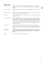
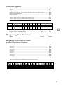
Software Revisions
Current software at time of printing:
Control Panel:
8.06
RKLCD Keypad:
4.04
HWB416:
3.00
EXP8:
1.01
Downloader
1.00
Speech:
RK36 Keypad:
TS16:
Bridge (Gate):
1.09
4.01
3.03
1.03
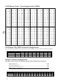
8.05 To 8.06 Panel Software Revision History
Changes
- Wiring diagram reflects latest change for UL Aug '98 requirements (page 12)
- Grounding requirements for UL installations (page 13)
Corrections
- Increased number of Central Station report codes to 49 (page 8).
- Added "Report Transmitter Low Battery to Central Station" originally omitted (page 24).
Enhancements
- Smoke Verification added to meet UL Aug '98 requirements (page 33).
- Speaker (Bell) Supervision added to meet UL Aug '98 requirements (page 34).
- Smoke Detector Low Battery Warning added to meet UL Aug '98 requirements (page 34).
- RF Jam Detection added to meet UL Aug '98 requirements (page 34).
New Locations
- Added locations 0251,0252, and 0253 for smoke verification under System Times section (page 38).
4
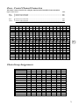
Table of Contents
1
2
Hardware and Wiring
Specifications ................................................................................................................................ 8
Items Included With the Control Panel ........................................................................................ 10
Inserting the Cabinet Lock .......................................................................................................... 11
Mounting the Control Board ....................................................................................................... 11
Wiring Diagram .......................................................................................................................... 12
Wiring Notes ............................................................................................................................... 13
System Terminals ........................................................................................................................ 14
X-10 interface Cord ..................................................................................................................... 16
Hardwire End-of-Line Resistor diagrams ..................................................................................... 17
Programming Overview
Programming .............................................................................................................................. 18
Program Mode ............................................................................................................................ 18
Locations and Values .................................................................................................................. 18
Automated Locations .................................................................................................................. 18
Exiting Program Mode ................................................................................................................ 18
Quick Start .................................................................................................................................. 19
System Input Overview ............................................................................................................... 20
Programming System Inputs ........................................................................................................ 20
System Setup Example ................................................................................................................ 21
3
Programming System Inputs to Zones
Using This Manual ...................................................................................................................... 22
Program a Zone .......................................................................................................................... 23
Zone Questions .......................................................................................................................... 23
System Input Automated Programming Locations ....................................................................... 24
Zone Type ................................................................................................................................... 24
Zone Options 1 ........................................................................................................................... 24
Zone Options 2 ........................................................................................................................... 24
Hardware Device Types .............................................................................................................. 25
Predefined Zone Assignments ..................................................................................................... 25
Hardwire Inputs .......................................................................................................................... 26
Alarm Point Transmitters - Supervised ......................................................................................... 27
Button Type Devices ................................................................................................................... 28
Button Functions ......................................................................................................................... 29
Editing Zone Programming ......................................................................................................... 30
Deleting a Zone .......................................................................................................................... 30
Programming System Inputs to Zones Terms ............................................................................... 30
Smoke Verification ...................................................................................................................... 33
Speaker (Bell) Supervision ........................................................................................................... 34
Smoke Detector Low Battery Warning ........................................................................................ 34
RF Jam Detection ........................................................................................................................ 34
5
4
System Options and Times
System Option Automated Programming Locations .................................................................... 36
System Options - Group 1 ........................................................................................................... 36
System Options - Group 2 ........................................................................................................... 36
System Options - Group 3 ........................................................................................................... 36
System Options - Group 4 ........................................................................................................... 37
System Options - Group 5 ........................................................................................................... 37
System Options - Group 6 ........................................................................................................... 37
Event Memory Log ...................................................................................................................... 37
System Times .............................................................................................................................. 38
Automatic Arming and Disarming ............................................................................................... 38
Monitor Trouble Conditions ........................................................................................................ 38
Bypass Options ........................................................................................................................... 38
Phone Access Options ................................................................................................................ 39
Event Memory Log ...................................................................................................................... 39
System Options and Times Terms ................................................................................................ 39
Communicator Automated Programming Locations .................................................................... 46
5
Central Station Features
Communicator Times .................................................................................................................. 46
Two-Way Options ....................................................................................................................... 46
Automatic Communicator Testing ............................................................................................... 47
Fail To Open (Disarm) / Fail to Close (Arm) ................................................................................. 47
Two-Way Digit Assignments ........................................................................................................ 47
Ademco Contact ID Report Codes .............................................................................................. 48
Report Codes .............................................................................................................................. 49
Dialer Options ............................................................................................................................ 50
Communicator Diagnostics ......................................................................................................... 50
User Communicator Test ............................................................................................................. 50
Central Station Terms .................................................................................................................. 51
Keypad Automated Programming Locations ............................................................................... 56
6
Keypad Functions
Key Function Values ................................................................................................................... 56
Keypad Option ........................................................................................................................... 56
Keypad Functions ....................................................................................................................... 57
TS16 Group 1 ............................................................................................................................. 57
TS16 Group 2 ............................................................................................................................. 57
Keypad Area Assignment ............................................................................................................ 57
User Code + Digit Functions ....................................................................................................... 58
Extended Monitor Times ............................................................................................................. 58
Extended Monitor Zone Type Assignment ................................................................................... 58
Vocabulary ................................................................................................................................. 59
Keypad Function Terms ............................................................................................................... 61
6
7
User Codes
User Code Options ..................................................................................................................... 65
Disappearing Code Activations ................................................................................................... 65
Assigning User Codes to Areas .................................................................................................... 65
User Code Terms ......................................................................................................................... 66
8
Control Channels
Automation Overview ................................................................................................................ 67
Automation Example ................................................................................................................... 67
Channel Activations .................................................................................................................... 68
Automated Control Channel Locations ....................................................................................... 69
Control Channel Options 1 ......................................................................................................... 69
Control Channel Options 2 ......................................................................................................... 69
Control Channel Options 3 ......................................................................................................... 69
Control Channel Options 4 ......................................................................................................... 69
Control Channel Locations .......................................................................................................... 70
Why Do X-10 Devices Turn Off Then On? .................................................................................. 70
System Triggers ........................................................................................................................... 71
X-10 Options .............................................................................................................................. 71
Output Control Assignments ....................................................................................................... 72
X-10 House Code - Unit Assignments (CHU) .............................................................................. 72
X-10 Input On/Off Command Assignments ................................................................................. 72
Output Control Assignments ....................................................................................................... 72
Zone - Control Channel Connection ........................................................................................... 73
Chain Group Assignments ........................................................................................................... 73
Control Channel Terms ............................................................................................................... 74
Work Sheets ................................................................................................................................ 79
7
1
Specifications
Electrical:
Voltage Input: 16.5 VAC 40 VA from supplied transformer
External Speaker: 10 Watt minimum, 8W horn type - Ademco 713 or equivalent. Total
speaker load must be between 4W and 16W.
Internal Speaker: Speaker supplied in all compatible keypads. For stand-alone operation
10 Watt minimum, 8W - Ademco 746 or equivalent. Total speaker load must be
between 4W and 16W. For UL installations, an Ademco 705 speaker must be connected to
the "EXT" and "COM" terminals.
Auxiliary Power Output: 13.5VDC, 1.85 AMP max - Not evaluated for UL installation
Switched Fire Output: 13.5 VDC, 1.85 AMP max
Two Wire Smoke Detectors: Up to 12 per system
Note: Switched Fire Output and Two Wire Smoke Detectors are not to exceed
10mA in a UL installation
Back-up Battery: 12VDC, 7AH gel cell. YUASA NP7-12 or equivalent.
For UL installations use 2 - batteries with SA5140-1 cable assembly
CAUTION: Total current draw of Auxiliary + Smoke + 4 wire bus power is not to exceed 2
Amps. In UL installations total current draw must not exceed 400mA. Test installation for 1
minute in alarm to ensure sufficient power.
Communicator:
Supports: 3/1, 4/1/1, 4/2 extended, Ademco Contact ID
49 report codes
DTMF and pulse dialing
DPDT line seizure
Two telephone numbers and two account codes, dial both numbers
Split reporting of selected codes
Alternate number dialing if primary number fails
Programmable number of dialing attempts
Programmable to enable or disable the communicator
Two-Way Voice:
Microphone inputs: 3 separate, individually controlled channels.
Microphone: 5V shielded 2 conductor omnidirectional electret condenser microphone.
Frequency response 50-10K. -64db sensitivity, TWM-25K or equivalent.
System Zones:
96 using the following inputs:
80 - programmable fully supervised wireless alarm points (with H series receiver)
16 - programmable fully supervised hardwire inputs on the control panel
64 - programmable fully supervised hardwire inputs on multiplexed expansion boards
1
- 2-wire smoke loop
8
- keypad alert
8
- wireless keypads (when available)
1
- local phone activation
1
- remote phone / phone line monitor activation
8
- X-10 sending units (Not UL listed for fire or burglary functions and are intended for
home automation.)
Auxiliary Outputs:
1
7
8
- Form C 10A 24VDC system relay
- Pull to ground, 12 volt, 100mA outputs, not to exceed 500mA total.
Not to be used in a UL installation
Speaker Output:
10 Watt internal siren driver with full speech
10 Watt external siren driver with full speech
Designed for use with 8W, 10 watt minimum speakers.
Total impedance for either driver not to drop below 4W
For UL installations use a Ademco 705 speaker which must be connected to "EXT" and "CON"
terminals.
Smoke Detectors:
ESL 429 Series
System Sensor 2112/24B
System Sensor 2112/24BT
System Sensor 2100
System Sensor 2100T
1
- 2 wire Photoelectric
- 4 wire Photoelectric (Not evaluated for UL installation)
- 4 wire Photoelectric (Not evaluated for UL installation)
w/heat sensor
- 2 wire Photoelectric (Not evaluated for UL installation)
- 2 wire Photoelectric (Not evaluated for UL installation)
w/heat sensor
Dimensions:
15.1" L x 13.05" W x 3.5" D w/ door.
System Keypads:
Fully spoken enunciation of zones and system status
6 Programmable manual activations
Lights and appliance control for home automation
3-way Monitor mode - Speech, Silence, Chime
Dimensions: 7" x 4 3/4" x 1" deep
Keypad Wiring:
4-wire bus
-red and black - power
-green and white - data
2-violet - audio
No smaller than 24 gauge, up to 50', 22 gauge over 50'
Microphone wire- 22 gauge, 2 conductor shielded
Transient Protection:
Multiple level surge filters are on all zone inputs, power supply, keypad connection, siren outputs,
auxiliary power supply, and the telephone interface. The circuit board is designed to provide spark
gap protection to catch high voltage impulses at the wiring terminals. Protective ground planes
surround sensitive areas preventing the spread of damaging voltage surges. Metal Oxide Varistors
(MOV's) are in all critical areas to further reduce surges. Sidactors and PTC Thermistors protect the
phone line input. Transient protection is most effective when the panel is earth grounded.
Nonvolatile Memory: Maintains programming options with no power to the control.
System clock:
Time-of-day clock with a backup circuit designed to deliver continuous power for two weeks on a
full charge.
System Watchdog:
All precautions have been taken to prevent spurious operation of the control caused by voltage
surges, however, temporary disruption of the microprocessor can occur, leading to improperly
processed routines. The system is equipped with a watchdog circuit that watches processor
operation and resets the microprocessor if an error should occur.
Supervision:
The following trouble conditions are always monitored:
Loss of AC power
Backup battery low voltage
Communicator failure
Phone line loss
High current conditions (system shorts)
Zone expansion failure
Receiver or bridge board failure (panel supervises bridge, bridge supervises receiver(s))
Transmitter supervision signals - trouble indication within 6 hours (if programmed)
9
1
Advanced Features:
Home automation capability
Phone access for both installer and end user
Speech synthesis
Alert memory in activation order
Event log memory in activation order
Audible RF test mode with serial number identification
Unattended upload/download programming (Not evaluated for UL installation)
Serial Interface (RS-232) printer / automation interface
Temporal fire notification tones
Items Included With the Control Panel:
Please examine the contents of the shipping box for the following items:
1
1
1
1
1
1
10
- Control Panel
- 16.5 VAC 40 VA Transformer
- Auxiliary Output Harness
- Microphone Harness
- Installation Manual
- Owners Manual
1
17
3
1
1
2
- Lock, key, and retaining clip
- 4.7KW 1/4 Watt Resistors
- Plastic mounting clip
- Package of 4 standoff screws
- Back up battery leads
- Wallet End User Instruction Cards
Inserting the Cabinet Lock
1
1. Remove the cabinet door
Retainer Clip
(Note Position)
2. Remove the lock knockout from the control cabinet door. Insert the
key into the lock. Position the lock in the hole making certain that
the latch will make contact with the latch bracket when the door is
closed.
3. Hold the lock steady, and insert the retainer clip into the retainer
slots. Position the clip as illustrated in order to permit easy removal.
Mounting the Control Board
1. Hang the three (3) mounting clips (provided) on the raised cabinet
(see below).
Retainer Slot
Locked
2. Insert the top of the circuit board into the slots at the top of the
cabinet. Be certain that the board rests in the correct row (see
below).
Unlocked
3. Swing the base of the board into the mounting clips and secure the
board to the cabinet with the accompanying screws (see below).
Control Board
Control Board
Can
Plastic Mounting Clip
11
1
Q
LR
W
D
Y
X LW
S F
W
D
X 2 Q
R
\ U G
D Q
OOL
X
[ R
X U
J
$ R
H W
W
OO
R X
1 S
H
U
D
V
W
U
R
O
\ I
G U
WD H D G
H
R H LOO
Y
7 F [ R
[ X U
H
S
$
LQ W
S
I
S
R
D
U Q R
W
H H R
S Q V Q
D
8
$ F H
U
W
P Q D
$ H
U P V
W
U
X X
W
S
D & W
X
2
U
R
W
V
L
V
H
U
V
Q
R
L
W
D
OO
D
W
V
LQ
/
8
H
Q
LO
I
R
G
Q
(
R
Q
W
X
S
Q
,
Q
2
J
Q
L
U
L
P
H
W
V
\
6
J
LQ
Q
R
LW
D
P
U
R
I
Q
L
P J
LQ
:P
D
U
H J
H R
U
6
3
K Q G
LW
R Q
Z L
LV D
G Y H U V
LU H P
S D
Z X U
H V J
E U
LD
G
\ R
W
D V W
L
X
P V S
H Q
V U
W
L
X U
S U R
I
Q
R
,
P
P
D
U
J
R
U
S
U
R
I
V
H
Q
R
=
P
R
&
P
R
&
R
W
V
W
X
S
Q
,
\
[ D
X O
H
$
5
W
.
II
2
U
P WR
F
6
H
H W
LU H
'
:
V
U
R
W
F
H
W
H
P '
R H
F N
U R
IR P
6
G
L
F
$
G
D
H
/
O
H
*
V
LH
U
H
W
W
D
%
H
S
\
W
Q
N H
F LW H
H
OD K U
% :*
W
&
$
W
Q
,
P
R
&
W
[
(
7
5
7
5
Z
D
U
G
W
Q
H
U
U
X
F
$
.
&
$ $ V
9 9 Q
D
U
7
P
G
H
5
P
Z
D
U
G
W
G
D
S
\
H
.
H
LU
NF DO %
HWL K :
QHHU *
GH 5
:
Q
U
*
G
H
5
[
X
$
P
R
&
.
0
6
$
H
J
LG
U
%
U
H
Y
L
H
F
H
5
OH
E
LW
D
S
&
' K
9 $
2
1
5
&
1
5
&
5
N
O
%
W
K
H
N
R
Q
H
U
U
:X
F
.
5
W
G
LH
O
S
S
X
V
.
H
N
R
P
6
H
LU
:
U
R
W
F
H
W
H
'
W
OH
R
L
9
W
H
O
R
L
9
6
H
Q
R
K
S
R
U
F
L
O
D
Q
LJ
6
H
Q
R
K
S
R
U
F
L
G
O
H
L
K
0 0 6
G
O
H
L
K
6
RJ-3 1X
6
H
Q
R
& K
S
' R
9 U
F
L
0
O
D
Q
LJ
RJ-3 1 X
P LU G
O
D
Q
LJ
H
K
W
W
Q
H
Y
H
U
S
R
7
J
Q
L
W
F
H
Q
Q
R
F
LV
G
N
F
R
K
V
I
Q R
U D N
V
L
:U
12
V
Q
LR
W
D
LF
IL
F
H
S
6
H
H
6
.
0
6
&
$
Q
2
.
$
&
' K
9 $
G re e n
0
6
6
Z
G
U
D
+
To Ho u se
P ho n e s
Fro m P ho n e
Com p any
Red
WV
X
S
Q
,
LF
H
LU
P
R
&
P
R
&
W
P
P V R U
Q I
R
G
Z H
WL
D
D
U H
OO
G F
[
WD W
V Q H
Q
H R
U W
,
U
W
/
X R
8 F
Q
U R H \
U
) J H
D W
U W
H D
Y
%
$
V
W
X
S
Q
,
\
[ D
X O
H
$
5
K
WF
L
Z
6
U
H
Z
R
3
H
K
W
R
OF
H
W
W
D
H
LQ
O
H
Q
R
K
S
OH
H
W
LV
K
W
J
LQ
F
L
Y
U
H
V
H
U
IR
H
E
N
F
MD
WL
Q
X
U
H
N
D
H
S
6
O
D
Q
U
H
W
[
(
LQ
0
W
W
D
:
W
V
Q
LR
W
D
F
LI
L
F
H
S
6
U
H
N
D
H
S
V
H
O
E
L
W
D
S
P
H R
H F
6 U
R
I
U
H
N
D
H
S
6
O
D
Q
U
H
W
Q
,
LQ
0
WW
D
:
W
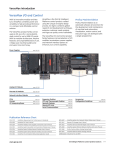
Wiring Notes
Grounding:
1
In UL installations where the Speaker Supervision option is enabled, grounding is not
permitted.
If grounding, it is recommended a system common be attached to a cold water pipe,
16ga. at 15 feet. Although cold water pipes have been the standard for earth ground,
it is very common in modern construction that a cold water pipe does not provide an
adequate ground due to the extensive use of PVC and other styles of "plastic" tubing.
The best method for grounding the panel is to locate the panel in an area with easy
access to the power company's earth ground.
Telephone Operation:
In the event of telephone operational problems, disconnect the control panel by
removing the plug from the RJ31X (CA38A in Canada) wall jack. We recommend
that you demonstrate disconnecting the phones on installation of the system. Do not
disconnect the phone connection inside the control panel. Doing so will result in loss
of your phone lines. If the regular phone works correctly after the control panel has
been disconnected from the phone lines, the control panel has a problem and should
be returned for repair. If upon disconnection of the control panel, there is still a
problem on the line, notify the telephone company and request prompt repair service.
The user may not under any circumstance (in or out of warranty) attempt any service
or repairs to the system. It must be returned to the factory for all repairs.
Communicator:
Connection of the fire alarm signal to a fire alarm headquarters or a central station
shall be permitted only with the permission of the local authority having jurisdiction.
The burglary alarm signal shall not be connected to a police emergency number.
Codes:
This equipment should be installed in accordance with National Fire Protection
Association's Standard 72 Chapter 2 (National Fire Protection Association, Battery
March Park, Quincy, MA 02269). Printed information describing proper installation,
operation, testing, maintenance, evacuation planning and repair service is to be
provided with this equipment.
Compliance:
This device complies with part 15 of FCC rules. Operation is subject to the following
two conditions: (1) It may not cause harmful interference. (2) It must accept any
interference that may cause undesired operation.
Complies with Part 68 of the FCC rules for direct telephone interconnect.
FCC Registration Number: 107USA-74224-AL-T
Ringer Equivalence: 0.8
Use USOC RJ-31X telephone connection jack. Complies with ANSI/UL 1023
Household Burglary Alarm System Units and ANSI/UL 985 Household Fire Warning
System Units.
Connections:
Use UL Listed Cable for all connections.
Testing:
Weekly testing is required to ensure proper operation of this system
Servicing:
To prevent the risk of shock, disconnect telephone line at telephone company supply
jack before servicing this unit.
Battery:
Battery normally need not be replaced for at least 3 years. Use a 12 volt 7Ah battery
(minimum). For all UL installations use two 12 volt 7Ah batteries wired in parallel.
13
1
System Terminals
House Phones:
The R1 and T1 terminals provide telephone service to the house if the installation
contains an RJ-31X terminal block for true phone line seizure.
Telephone Company:
The incoming telephone service is wired through an RJ-31X jack to the R and T
terminals on the control panel. If regular phone service is unavailable, the system will
provide power and a distinct system tone to all in house phones.
Speakers:
The control panel contains amplified internal and external siren drivers. Both internal
and external speaker connections require 8W , 10 watt (minimum) speakers. The "EXT"
and "COM" (speaker common) terminals provide full volume audio during activation.
Mount the external speaker(s) in an area that is unaccessible to intruders and will
provide a sufficient volume during an activation.
The INT and COM terminals produce speech, low volume monitor beeps, keypad
echo beeps, system status, pre-alarm warning, and a high volume alert during
activation. Typically, in non UL installations, the speakers (16W) in the RK series
keypads are used as the only source for providing internal system audio; however in a
UL installation the RK series keypads must be supplemented with an Ademco 705
speaker connected to the "EXT" and "COM" terminals. See Specifications for
compatible speakers.
Wire all speakers in a series/parallel combination that does not allow the impedance for
either the internal or external output to drop below 4W.
Transformer (AC Power):
Use a 16.5 VAC, 40 VA transformer (supplied) to supply AC power. Do not connect the
transformer to a switched AC outlet. If an AC failure occurs, after 1 minute
(programmable) the system will speak "POWER OFF", the keypad power LED will turn
off, and the keypad status LED will begin to flash. After requesting system status the
system will speak "POWER OFF" and the status LED will become solid. AC failure and
restore conditions can be transmitted to the central station.
2-Wire Smoke Detectors: 2-wire smoke detectors are connected to the "SMK+" and "SMK-" terminals. Be certain
to observe polarity. Smoke power reset is built into the panel by entering a valid full
function user code followed by the "6" digit. A 4.7KW resistor must be wired in parallel
with the last detector in the loop. If a resistor is not used, or if there is a break in the
loop, a TROUBLE indication will occur. Up to 12 2-wire smoke detectors can be
powered by the smoke power supply. A high current situation on the smoke power
circuit can be indicated at the keypad and/or communicated to the central station.
4-Wire Smoke Detectors: The "SMK+" terminal supplies up to 1.85 AMPs of power. A 4.7KW resistor must be
wired in parallel with the detector and wired to a zone input. Power is drawn from the
SMK+ and COM terminals. Smoke power reset is built into the panel and is reset by
entering a valid full function user code followed by the 6 digit. A high current situation
on the smoke power circuit can be indicated at the keypad and/or communicated to the
central station. Use of 4-wire Smoke Detectors not evaluated for UL installation.
Auxiliary Power:
12V+ Auxiliary power for hardwire devices such as motion detectors and glass break
detectors is available on the "AUX" terminal. The auxiliary output is protected at 1.85
Amps. A high current situation can be indicated at the keypad and/or communicated to
the central station.
The Destiny-6100 is compatible with the ADEMCO 4142-BLK removable terminal strips. If
necessary, these connectors allow for quick replacement of the control board.
14
Keypad 4-wire Bus:
Connect corresponding 4-wire bus colored wires from peripheral devices to the
appropriate terminals. Additional devices may be daisy chained or wired in parallel to
the system board. The 4-wire bus is protected at 1.85 Amps. A high current situation
can be communicated to the central station.
Auxiliary Relay:
A programmable relay is available on the "RC", "RNC" , and "RNO" terminals. Use "RC"
for relay common, "RNC" for relay normally closed or "RNO" for relay normally open.
Battery Leads:
Connect the red lead to the + battery terminal and the black lead to the - battery
terminal. If enabled, the battery is tested every 180 seconds to ensure it is present and
charged. A low battery condition can be indicated at the keypad and/or communicated
to the central station.
Auxiliary Outputs:
An auxiliary output wire harness is supplied for J4. There are 7 programmable output
pins and 3 power pins. Pins 1-7 will provide a ground path when activated. Pins 8, 9 &
10 supply +12V DC. Do not exceed 100 mA per pin or 500mA total. These outputs
are intended to drive relays with a coil impedance of 500W or greater or any other
device requiring 100 mA or less. The outputs are not intended to power devices without
the use of a relay. It is acceptable to power an LED when a 1 to 4.7KW, current limiting
resistor is wired in series. Use of Auxiliary Outputs is not evaluated for UL installation.
See Control Channel section for programming information.
Microphone Input:
A microphone wire harness is supplied at J1. Consult the Specifications section to
determine compatible microphones. Up to 3 microphones can be wired in parallel to
each of the 3 microphone inputs. Please note, if multiple microphones are wired to a
single microphone input, the microphones must be turned off and on as a group. It is
recommended to only wire 1 microphone to each of the 3 input channels allowing a
central station to have full control of each microphone during a two-way session. Use
of two-way voice is not evaluated for UL installation.
Power Switch:
Located in the center of the control board is a black slide switch which controls all
power (including the battery) to the system. Up = ON; Down = OFF.
Volume Adjustment:
The potentiometer marked "VOLUME" on the left side of the control board controls the
volume level of any system generated speech and the key depression feedback beeps.
Using a small screwdriver, turn the potentiometer to obtain the desired volume.
Clockwise increases volume. This adjustment will not the affect alarm notification
volume from the speaker during an activation.
Program Switch:
Located in the upper right corner of the control board, this switch is used to return the
system to various defaults. Holding the button down and releasing after a specific
number of "beeps" will activate different system functions:
beeps
1
3
5
10
other
Hardwire Inputs:
Action
Return user code 1 to default: 1,2,3,4
Enter direct connect mode (Same as 9952 in program mode)
Return service (program) code default: 9,1,7,3
Default panel
Three error beeps: no programming is affected.
There are 16 hardware inputs on the control panel. Through programming, each input
can be wired in one of three ways: with a 4.7KW end-of-line resistor (EOLR), without an
EOLR, or with class-A 2-resistor supervision.
15
1
1
Two-Way Adjustment:
The potentiometer marked "2-WAY VOL" controls the volume level of voice over the
phone line to the inside speaker during two-way communication or paging. Using a
small screwdriver, turn the potentiometer to obtain the desired volume. Clockwise
increases volume. This adjustment will not the affect alarm notification volume from the
speaker during an activation. Use of two-way voice is not evaluated for UL installation.
Upload / Download LED: At the top right of the board is a yellow LED labeled "U/D" which is illuminated when
there is a modem to modem connection during upload or download.
POWER LED:
At the top right of the board is a red LED labeled "POWER" which is illuminated when
the system is receiving power.
STATUS LED:
At the top right of the board is a green LED labeled "STATUS" which flashes to show the
microprocessor is functioning. An incoming ring detection will cause this LED to flash
very fast.
Dial LED:
At the top right of the board is a red LED labeled "DIAL" which is illuminated during
digital communication and remote phone access. The Dial LED is used as a diagnostic
tool to analyze communication problems. The number of flashes after a failed attempt
correlates to the communication stage that caused the system to fail. See
"Communicator Diagnostics" for more information.
Phone LED:
At the top right of the board is a green LED labeled "PHONE" which is illuminated when
the system's supervision of the phone line verifies a valid phone line on "R" and "T." If
the system does not confirm a phone line, the LED will turn off. Phone line failures can
be indicated at the keypad as well as sound a local alarm. Phone line restoration can be
communicated to the central station.
X-10 TW-523 Interface:
Plug a standard RJ-12 cord into J5 on the middle right side of the board when using the X10 TW-523 (X-10 Pro PSC05) module for lighting options. The termination of the four
wire connection will be another RJ-12 jack plugged into the TW-523. The cord must
have four wires (see "X-10 interface Cord"). 2-wire cords will not work. Use of X-10 is
not UL listed for fire and burglary functions and is intended for hom automation. See
Control Channel section for programming information.
X-10 Interface Cord
A 4-conductor phone cord must be used to connect an X-10 TW-523 (X10-Pro PSC05) to the interface jack on the
control panel. Maximum cord length is 15 feet. The conductors must be in the following order:
Y G R B
16
B R G Y
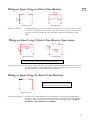
Wiring an Input Using an End-of Line Resistor
1
4.7KW
4.7KW
Normally Closed
Single E.O.L Resistor:
Normally Open
Traditional inputs are wired with a single end-of-line resistor. An open or short is treated
as an open. A single end-of-line resistor is only effective if the resistor is placed after the
last device wired in an input loop. This is the only suitable wiring method for smoke
loops.
4.7KW
4.7KW
4.7KW
Wiring an Input Using 2 End-of Line Resistor Supervision
4.7KW
Normally Closed
Normally Open
Only use 1 End-of-Line Resistor on smoke detector loops.
Two Resistor Supervision: This wiring arrangement allows the system to detect and handle open loops and shorts as
a trouble condition. Through programming, trouble conditions can be communicated to
the central station and show trouble status on a keypad.
Wiring an Input Using No End-of Line Resistors
All inputs that do not use end-of-line resistors
must be wired with a normally closed sensor
Normally Closed
No End-of-Line Resistor:
The option is recommended only for "non-perimeter" zones that do not require tamper
protection. There is no tamper protection (other than a cut loop shows an open) without
a resistor and all loops that do not use a resistor must be normally closed. No End-of
Line Resistor is not evaluated for UL installation.
17
Programming
2
System options are contained in EEPROM. Each programmable section of memory has a 4 digit location and a
three digit value. To reduce the amount of programming necessary, each location is supplied with a default value.
The programming process can be simplified and the chances of programming errors can be reduced by obtaining a
copy of the DOS based PC software available from APEX, the BBS at 919-954-0318 or download from our web site
(www.ademco.com/apex). The BBS settings are no parity, 8 bits with 1 stop bit, and connection speeds up to 28.8
baud.
Program Mode
To program new values into memory locations, it is necessary to first place the system into program mode. This is
achieved in the same manner from a keypad or remote telephone; from keypad mode (anytime the system is in an
idle state) enter the service code (factory default of 9,1,7,3). The system will respond with ENTER PROGRAM
MODE. The LED's on keypads will turn off (RK36) or the display will show "Program Mode Active" (RKLCD).
Locations and Values
Programming requires the entry of a valid 4 digit program location followed by the entry of a 3 digit programming
value. When a valid program location is entered, the inside speaker will emit one beep. Press the H (# from
telephone) and the system will speak the current value in the location. To establish a new value, reenter the 4
digit location and type the desired new value after the single confirmation beep. The system will confirm the new
program value by speaking the location followed by the value. To cancel current entries at any time prior to the
system speaking the programming confirmation, press A (* from telephone), at that point a new location can be
entered. If the system responds with three beeps after a location is entered, an invalid location has been entered.
Values entered into undocumented locations may cause spurious system operation.
Automated Locations
The first set of locations in most sections of this manual are titled "Automated Programming Locations." An
automated location is designed to reduce the amount of programming required by the installer. Based on the
programmers inputs to prompted questions, the system does the required conversions and automatically places the
correct values in memory locations. This process saves the installer time and reduces the risk of potential
programming errors. Instead of entering a location and a value, enter the desired memory location (they always
start with 9). The system will prompt for programming information. A full explanation of each automated prompt
is located in the chapter in which the location appears.
Exiting Program Mode
To exit program mode, enter 9,8,9,9, instead of a program location, the system will respond with EXIT PROGRAM
MODE." If a key (or digit) is not pressed within the time period programmed in location 0781, the system will
automatically exit program mode.
18
Quick Start
Keypad connection:
Connect a hardwire keypad to keypad terminals on the control board, be certain to
properly match the colors as follows: Black to BLK, Red to RED, Green to GRN, White
to WHT.
2
Speaker connection:
Connect the violet keypad speaker leads to the INT and COM terminals on the control
board.
Power connection:
Connect the power transformer to the AC terminals on the control board and plug the
transformer into an unswitched 120 VAC outlet.
Apply power:
Turn the power switch to the ON position (up). Wait for a start tone(s) followed by a
pause and two beeps.
Setting time and day:
The panel MAY prompt "Press 2 and 8 to set time" if the clock was not set prior to transit
or if the capacitor responsible for sustaining the clock dissipated during transit and
stocking. Press the 2 and 8 keys on the keypad simultaneously. The panel will prompt
for a 4 digit time (use a leading 0 for times under 10:00), followed by a prompt for AM
or PM. The next prompt is for the day of the week (1-Sunday, 2-Monday, 3-Tuesday,
4-Wednesday, 5-Thursday, 6-Friday, 7-Saturday). Enter a two digit month, two digit
date and two digit year.
Arm and disarm:
Press the A key on the keypad and the green AWAY LED will light. ARMED TO
AWAY will be heard through the speaker. To disarm, push 1,2,3,4 (default Primary User
Code) on the keypad. The AWAY LED will go out and CONTROL IS DISARMED will
be heard.
Default Panel:
To ensure erroneous values are not stored in memory from the manufacturing and/or
testing the panel should be defaulted before installation. Enter 9,1,7,3 followed by
9,9,8,2.
Program:
Proceed with programming to suit the installation.
19
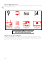
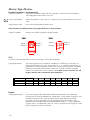
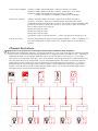
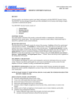
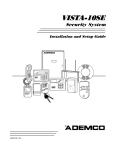
System Input Overview
2
The diagram below shows each of the available system input types and the maximum number of each device that
can be integrated into the system.
8
X-10 Sending
Units
80 Wireless Alarm
Points / Portable inputs
(with H series receiver)
1
Two Wire Smoke Loop
8
Wireless Keypads
(When available)
8
Keypad Alarm Points
16
Hardwire System
Inputs
1
Phone Alarm
64
Expansion Hardwire
Inputs
Each input used is assigned to a System Zone.
There are 96 System zones available.
Programming System Inputs
Before programming, determine all of the system inputs that are being used and assign a zone number for each
input. All zones may have one input and each input can only be assigned to one zone. Each loop on a multiple
input transmitter is considered to be a single input. Therefore, if all three inputs on a three loop transmitter are
being used, each input is assigned to a different zone.
20
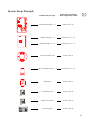
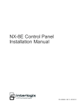
System Setup Example
Hardware Device Types
System Zone Assignments
* Zone Assignments - flexible
System Board Inputs 1-16
System zone 1-16
HWB 416 Inputs 1 - 8
System zone 17 - 24
HWB 416 Inputs 9 - 16
System zone 25 - 32
Two Wire Smoke Loop
System zone 33
5817 Transmitter Inputs 1 - 3
System zone 34 - 36
5804 Panic
System zone 37
Local Phone Panic
System zone 94
Phone Line Monitor
System zone 95
System Keypads
System zone 96
2
21
Using This Manual:
This manual is not designed to be read like a book. The layout is intentionally designed as a reference guide that
allows quick access to information while programming the system. It is strongly recommended that a first time
installer attended training or bench test a system before attempting the first installation. For information on APEX
training contact the sales department at 800-272-7937.
3
The layout of this manual is broken into eight separate sections. Each section begins with locations and ends with
a full description of each option found in the location section. There are four styles of programming information in
the system:
Automated Locations:
Automated Location prompt for specific information and automatically record the
appropriate information into the correct locations.
Value Locations:
A documented location that contains a specific value (i.e. time, user number, etc.)
Option Location:
Most system options require a total of option values to be placed in a location.
Example:
Options - Enter Total
Location
Value
................................
Speak remote control menu (Not evaluated for UL installation)
001
Speak time and date when time is requested .............................................................. 002
Speak temperature when time is requested (See "Using a TS16") ................................ 004
Enable answer service override callback ..................................................................... 008
Default .............................................................................................. 0135 ................ 003
The bold 001 and 002 states the values are included in a defaulted panel. To include the 3rd option,
add 004 and enter the total (007) in location 0135. If no options were selected, enter 000.
Charts:
Charts are used to provide a large number of locations in a small space. Depending
on how the section is used, the locations in charts contain either an option value or
a discreet value.
Example:
Options
Value
..................................................................................
2 end-of-line resistor supervision
064
No end of line resistor (Not evaluated for UL installation) .......................................... 128
Default (1 end-of-line resistor) ..................................................................................... 000
The inputs across the top refer to which of the 16 terminals across the top the location is referring to.
Below each input is a location. To program system input number 11 for 2 resistor supervision, enter
2474,064. Each location referenced above is shipped with a 000 default.
,QSXW
2SWLRQV
22
'HIDXOWV
Program a Zone
Each input used in the system must be assigned a zone number and zone options to allow the system to process
opens and closes in the desired manner. To simplify the process, the system has an automated menu system that
only requests a small amount of information. Based on the responses, the software will automatically set defaults
and establish the link between the zone number and hardware.
The first five questions for zone programming are always the same. During these questions the Monitor button will
return to the previous question, F1 will play the current value, and F2 will accept the current value and advance to
the next prompt.
At any time during the zone programming process, the A key will clear an entry for the current prompt. The H key
returns the system to the first prompt. From the first prompt, the H key will exit to program mode.
Note: when H is pressed, any programming changes for the current zone are lost, pressing H after an F2
confirmation will still erase any changes. Zone programming selections are saved only after the final
question is answered and the system advances to the "Next Zone" prompt.
Zone Questions
Enter program mode:
Default 9,1,7,3. The panel will speak "Enter Program Mode"
Enter 9,9,4,0:
Program a zone automated location.
2 digit zone number:
Enter the desired zone number 01 - 96. For zones under 10 use a leading zero (1=01).
3 digit zone type:
Enter the desired three digit value from the Zone Type chart (next page). If the
hardware device type for this zone is a under the "Button" device heading, use 015 as
the zone type.
3 digit zone options 1:
Add the values for the desired options in the Zone Options 1 chart (next page) and enter
the total as a three digit number. Use a leading zero as necessary. If the hardware
device type for this zone is a under the "Button" device heading, use 000 as Option 1.
3 digit zone options 2:
Add the values for the desired options in the Zone Options 2 chart and enter the total as
a three digit number. Use a leading zero as necessary. If the hardware device type for
this zone is a under the "Button" device heading, use 000 as Option 2.
3 digit device type:
Enter the three digit number corresponding to the device for this zone in the
Hardware Device Type chart (next page).
To accept device:
If the device number is correct, press F2. Otherwise, press monitor and enter the correct
value.
Once F2 is pressed, Monitor will not step back to the device prompt.
If a mistake has been made, press H, and reprogram the zone
The common Zone information is complete, proceed to the appropriate hardware device
type questions for information on prompts that correspond to specific hardware. This
information is found immediately after the zone options on the next page.
23
3
System Input Automated Programming Locations
Program Zone (From system keypad only) ........................................................................
Place system in RF field strength mode and speak serial number .....................................
Exit RF field strength mode ..............................................................................................
Exit program mode ...........................................................................................................
3
9940
9951
9950
9899
* Zone Type
Type
Value
Exterior Instant ................................................................................................................... 000
Exterior Delay 1 ................................................................................................................ 001
Exterior Delay 2 ................................................................................................................ 002
Interior Instant ................................................................................................................... 003
Interior Delay 1 ................................................................................................................. 004
Interior Delay 2 ................................................................................................................. 005
Fire .................................................................................................................................... 006
Panic ................................................................................................................................. 007
Silent Panic ....................................................................................................................... 008
Emergency ......................................................................................................................... 009
Follower ............................................................................................................................ 010
Aux Type 1 ........................................................................................................................ 011
Aux Type 2 ........................................................................................................................ 012
Day Zone .......................................................................................................................... 013
Step arming ....................................................................................................................... 014
Button device type ............................................................................................................ 015
Sunrise / Sunset ................................................................................................................. 016
Disable .............................................................................................................................. 255
Zone Options 1
Options - Enter Total
Value
Report Alarm Activation to Central Station ....................................................................... 016
Report Transmitter Low Battery to Central Station ............................................................. 032
* Display open status at keypad ........................................................................................... 064
Default .............................................................................................................................. 000
Zone Options 2
*+
*+
*+
*+
*+
*+
*+
*+
*
*
*
Options - Enter Total
Value
Area 1 ................................................................................................................................ 001
Area 2 ................................................................................................................................ 002
Area 3 ................................................................................................................................ 003
Area 4 ................................................................................................................................ 004
Area 5 ................................................................................................................................ 005
Area 6 ................................................................................................................................ 006
Area 7 ................................................................................................................................ 007
Area 8 ................................................................................................................................ 008
Suppress Speech/Beeps for monitor ................................................................................... 016
Suppress OPEN from being spoken during monitor ......................................................... 032
Suppress siren on activation .............................................................................................. 064
Default .............................................................................................................................. 001
* Options are ignored for all button type devices.
+ Choose only ONE area for the zone to be assigned to ONLY if split arming is being used.
Split Arming is not permitted in a UL installation.
24
Hardware Device Types
Hardwire Inputs
Type
Description
Value
.........................................
..................................................
System Controller
16 hardwire inputs
000
HWB416 ....................................................... 16 Zone expansion board ....................................... 001
System Smoke Loop ...................................... 2-Wire smoke loop ................................................. 002
Local Telephone ........................................... Local telephone 5 zero activation ......................... 015
Phone Line Monitor ...................................... Loss of phone line activation ................................. 021
TS16 -only use 32-127 degrees F ................... Temperature Sensor ................................................ 022
3
Alarm Point Transmitters
Type
Description
Value
....................................................
..............................
5816 (MN)
2 input alarm point transmitter
003
*5816TEMP ..................................................... Low temperature transmitter .................................. 004
5817 .............................................................. 3 input alarm point transmitter .............................. 005
5818 .............................................................. Recessed door transmitter ...................................... 006
*5819 .............................................................. 3 input shock transmitter ....................................... 007
5890 .............................................................. Passive Infrared ...................................................... 011
5849 .............................................................. Shock / Glass Detector .......................................... 012
5806 .............................................................. Smoke Detector ..................................................... 018
5807 .............................................................. Smoke Detector ..................................................... 018
5808 .............................................................. Smoke Detector ..................................................... 019
* Not evaluated for UL installation
Button Type Devices - PROGRAM ZONE TYPE AS 015
Type
Description
Value
..............................................................
.....................................................
5801
4 button portable
008
*5802 .............................................................. 1 button portable ..................................................... 016
*5802 CP ........................................................ 1 button portable ..................................................... 017
*5802 MN ...................................................... 1 button portable ..................................................... 009
5804 .............................................................. 4 button portable ..................................................... 010
X-10 .............................................................. X-10 Channel On/Off Command ............................. 020
Keypad .......................................................... Keypad alert activations ......................................... 013
* Not evaluated for UL installation
Predefined Zone Assignments
From a defaulted panel the following zones are automatically assigned:
Zone 94:
Local phone
This is predefined to allow local phone access at default. To enable a
5 "0" activation as an input, assign a zone type to zone 94.
Zone 95:
remote
Phone Line Monitor &
The phone line monitor device type must be assigned to a zone for
Remote Phone
phone "User Code + Digit" activations. To enable the phone monitor,
assign a zone type (recommended zone type: aux) to zone 95. When a
phone line loss occurs, the zone will show open and beep the keypad as
a trouble violation. Pressing the status button silences the beep.
Zone 96:
Hardwire keypad
All keypad activations for RKLED and RKLCD(#1) are defaulted to report
as zone 96.
25
Hardwire Inputs
System Controller
2 digit Input Number:
Enter the hardwire loop on the system controller being used. Valid inputs are 1-16.
The default for this input type is a single end-of-line resistor. This option can be changed to no endof-line resistor or full 2 resistor supervision by entering the appropriate value in the locations below.
3
Options
Value
Speaker supervised Zone ................................................................................................... 008
Treat trouble as an activation ............................................................................................ 016
2 end-of-line resistor supervision ........................................................................................ 064
No end of line resistor (Has not been evaluated for a UL installation) .............................. 128
Default (1 end-of-line resistor) ........................................................................................... 000
,QSXW
2SWLRQV
'HIDXOWV
HWB416 Zone Expansion Board
1 digit group number:
Each HWB416 has two groups of 8 zones that are separately controlled by dip switches.
Inputs labeled 1-8 are the 1st group and 9-16 are the second group. If a second HWB416
is added to the system, the 1st section would be group three and inputs 9-16 would be
group four. Enter the appropriate group number for the desired input. Valid inputs are 18 (lower inputs on HWB416 #1 through the high group of inputs on HWB416 #4).
1 digit input number:
Enter the input number from the selected group. Lower inputs (1-8) are entered as written
on the HWB416. For zones in the high group (9-16), subtract 8.
Example: To program input 15 from group 4 (HWB416 #2) enter input number 7
The default for this input type is a single end-of-line resistor. This option can be changed to full 2
resistor supervision by entering the appropriate value in the locations below.
Options
Value
2 end-of-line resistor supervision ........................................................................................ 128
Default (1 end-of-line resistor) ........................................................................................... 000
+:%*URXS
2SWLRQ
System Smoke Loop
There are no additional questions for this input type.
Local Telephone
While in local phone keypad mode, a user can activate a zone by entering 5 zeros. This zone type is traditionally
programmed as a 24 hour panic. There are no additional questions for this input type.
Phone Line Monitor
The phone line monitor input becomes active upon loss of phone line. For notification at the keypad, this input can
be programmed as an auxiliary zone type for enunciation at the keypad, a day zone for extended monitoring and
alerts while armed, or a 24 hour panic for alarm activation upon loss of phone line (not recommended). There are
no additional questions for this input type.
26
TS16 - Only use between 32 - 127 degrees F
Temperatures from a TS16 can be used as a zone input. The system will prompt:
2 digit input number:
The system supports up to 16 separate TS16s. Enter the TS16 address to be used. Legal
values are 1 - 16. Use the locations below to program the TS16. A temperature at or
above the High point is an open. A temperature at or below the Low temperature is an
open. The hysteresis setting determines how far the temperature must rise (above Low
setting) or fall (below High setting) for the zone to restore. TS16 inputs are not evaluated
for UL installation.
Options - Enter Total
Location
Value
Enable TS16 ....................................................................................................................... 001
Speak all temperature transmissions .................................................................................. 002
Speak when time is requested ........................................................................................... 004
Open zone at High Temperature setting ............................................................................ 016
Open zone at Low Temperature setting ............................................................................. 032
Hysteresis 2 degrees .......................................................................................................... 064
Hysteresis 4 degrees .......................................................................................................... 128
Default (TS16 disabled) ..................................................................................................... 000
76
'HIDXOWV
2SWLRQ
+LJK6HWSRLQW
/RZ6HWSRLQW
Note: If a Low setpoint and High setpoint are being used then: Low + hysterics must be less then High - hysterics.
Hysterics settings of 2 and 4 can be added (192) for a hysterics of 6 degrees. If values 64 and 128 are not
used, the hysteresis is 1 degree.
Alarm Point Transmitters - Supervised
7 digit serial number:
Enter the serial number listed on the bar code label. Only enter the seven numbers. The
leading letter on the label is not used.
Accept serial number:
If the serial number is correct, press F2. Otherwise, press monitor and enter the correct
value.
The following is only prompted on multiloop transmitters:
1 digit input number:
Use the transmitter loop locations to determine the input.
5816 (MN)
5817
5819
Loop 2
Loop 2
Loop 1
Loop 1 Loop 2
Loop 3
Loop 3 Loop 1
(Shock Input)
27
3
Button Type Devices
Portable Transmitters - Not Supervised
3
7 digit serial number:
Enter the serial number listed on the bar code label. Only enter the seven numbers.
The leading letter on the label is not used.
Accept serial number:
If the serial number is correct, press F2. Otherwise, press monitor and enter the correct
value.
3 digit function code:
Enter code from the Button Functions chart.
If the transmitter has multiple buttons, the prompt will advance to the next button:
2 digit user number:
Enter the user number assigned to arming functions.
5801
5804
Button 3
Button 2
Button 3
Button 4
Button 1
Button 4
Button 2
Button 1
X-10
X-10 On or Off commands can be used as a zone input. The system will prompt:
1 digit input number:
,QSXW
'HIDXOWV
&+8$VVLJQPHQW
2Q%XWWRQ)XQFWLRQ
2II%XWWRQ)XQFWLRQ
Keypad
1 digit keypad number:
28
The system supports up to 8 separate X-10 addresses as valid inputs. Enter the X-10
input channel number to be used. Legal values are 1 - 8. Use the locations below to
program the X-10 CHU assignment (listed in the "Control Channel" section), and button
functions for On and/or Off commands. When an X-10 input is used for an arming
function, the system refers to user 32 options. X-10 inputs are not UL listed for fire and
burglary functions and are intended for home automation.
The system supports addressable and non-addressable keypads. Each addressable
keypad (up to 8) has programmable key combinations, a zone number assignment, and
the ability to program a four word description that is spoken during keypad alert
activations. For more information, see the Keypad section of this manual. Those
keypads that are not addressable share keypad address number 1. For non-addressable
keypads, enter 1, for addressable, enter 1-8. Note, if keypads are not assigned to a zone
they are assigned to zone 96 by default.
Button Functions
Option
Value
........................................................................................................................
Speak Time
000
Toggle Monitor .................................................................................................................. 001
Speak Long Term Memory ................................................................................................. 003
Silence Day Zone .............................................................................................................. 004
Speak Status ...................................................................................................................... 005
24 Hour Fire ...................................................................................................................... 006
24 Hour Panic .................................................................................................................... 007
24 Hour Silent ................................................................................................................... 008
24 Hour Emergency ........................................................................................................... 009
Enter Remote Control ........................................................................................................ 012
Extended Monitor A ........................................................................................................... 013
Extended Monitor B ........................................................................................................... 014
Enter Bypass Mode ............................................................................................................ 015
Set Time ............................................................................................................................ 016
Step Arming ....................................................................................................................... 017
Arm to AWAY .................................................................................................................... 018
Arm to HOME ................................................................................................................... 019
Disarm ............................................................................................................................... 020
Sunrise ............................................................................................................................... 021
Sunset ................................................................................................................................ 022
Remote System Mode (for use with RS-232 adapter only) ................................................. 023
Output Control #1 .............................................................................................................. 024
Output Control #2 .............................................................................................................. 025
Output Control #3 .............................................................................................................. 026
Output Control #4 .............................................................................................................. 027
Output Control #5 .............................................................................................................. 028
Output Control #6 .............................................................................................................. 029
Output Control #7 .............................................................................................................. 030
Output Control #8 .............................................................................................................. 031
Output Control #9 .............................................................................................................. 032
Output Control #10 ............................................................................................................ 033
Output Control #11 ............................................................................................................ 034
Output Control #12 ............................................................................................................ 035
Output Control #13 ............................................................................................................ 036
Output Control #14 ............................................................................................................ 037
Output Control #15 ............................................................................................................ 038
Output Control #16 ............................................................................................................ 039
Disable .............................................................................................................................. 255
Note:
3
"Output Control Channel" options and channel assignment locations are published in the
"Control Channels" section. See "Key Function Values" in the Keypad Functions section for
definition of terms.
29
Editing Zone Programming
3
Once a zone has been programmed, the system provides a quick method for editing zone values. Enter 9,9,4,0
followed by the zone number. As each input prompt is played, press F1 and the system will replay the current
value. To change the configuration, enter a new value. To accept a current value, press F2. The Monitor button
will return to the previous prompt. The Monitor button will not return to prompts once the system has asked for F2
to confirm. Any changes made only take effect if the final question is answered and the system speaks exit.
Deleting a Zone
A zone can be deleted by entering a device type of 255.
Programming System Inputs to Zones Terms
System Input Automated Programming Locations
RF Strength Mode:
This mode reduces the sensitivity of the receiver and speaks the serial number for all
5800 signals.
Exit Program Mode:
Removes the system from program mode and places the system in keypad mode.
Zone Types
Exterior Instant:
Exterior instant zones instantly sound an alarm when the system is armed to HOME,
AWAY or Night. When the system is not armed, monitor mode is active, and the zone
is programmed to show open/close status at the keypad, the system will speak the zone
description or sound a monitor beep when the zone input is activated. Exterior Instant
zones can be programmed to sound an alarm when the input is activated during an exit
delay (System Options - Group 2, option 008). Otherwise, the exterior instant zone will
respond in the same manner as when the system is not armed.
Exterior Delay #1:
Tripping an exterior delay input places the system into a pre-alarm mode if the system is
armed to AWAY or HOME (unless "No entry delay for Exterior Delay #1 in Home" is
selected in System Options - group 2). The system refers to entry delay time #1 to
determine the pre-alarm duration. If pre-alarm expires without a user entering a valid
disarm code, the system will sound an alarm. When the system is not armed, monitor
mode is active, and the zone is programmed to show open/close status at keypad, the
system will speak the zone description or sound a monitor beep when the zone input is
activated. During an exit delay, Exterior Delay zones respond in the same manner as
when the system is not armed. In Night mode, this zone type acts an exterior instant.
Exterior Delay #2:
Same as above but uses programmable entry delay time #2.
Interior Instant:
The interior instant zones are active in the AWAY mode only. No monitor function is
provided for interior zones (except during extended monitor). During an exit delay, an
opening is ignored.
Interior Delay #1:
Same as Exterior Delay #1 except active only in AWAY mode and no monitor is
provided.
Interior Delay #2:
Same as Exterior Delay #2 except active only in AWAY and Night mode and no monitor
is provided. Uses delay time #2.
Fire:
Fire zones respond with short high volume tones over the internal and external speakers.
The system will alternate between the tones and speaking "FIRE, FIRE," followed by the
up-to-four-word zone description, and "REMAIN CALM, LEAVE IMMEDIATELY."
Panic:
Panic zones respond with a high volume alert on both the internal and external speaker.
The alert consists of a pulsed tone followed by "ALERT, ALERT", and the up-to-four-word
description of the zone.
30
Silent Panic:
Silent panic zones respond by activating the communicator. An activation appears in
system status, however no audible indication is given.
Emergency:
Emergency zones respond though inside speakers only. The alert consists of a pulsed
tone followed by "ALERT, ALERT", and the up-to-four-word description of the zone.
Follower:
An interior follower zone is active in the AWAY mode only. A follower acts as an
instant zone providing an exterior delay zone is not previously tripped. When the
system is in pre-alarm, the follower follows the pre-alarm time. No monitor function is
provided and during an exit delay, an opening is ignored.
Auxiliary:
Auxiliary zones are non-burglary zones designed to provide an automation, information,
or service input to the system. This zone type does not activate an alarm even when
the system is armed. When monitor mode is active, the zone is programmed to show
open/close status at keypad and speak auxiliary zone type (System Option - Group 5,
option 001) is enabled, the system will speak the zone description or sound a monitor
beep when the zone input is activated. An auxiliary zone can be programmed to alert
the central station.
Day:
When the system is not armed a Day zone will cause an Extended Monitor activation
and can send a Day Zone Trouble report to the central station. When the system is
armed a Day Zone will act like an Exterior Instant. A day zone extended monitor
activation can be cancelled with the "Silence Day Zone" button function.
Step Arming:
The arm/disarm zone type is used for momentary arming inputs such as a keyswitch or
touchpad. Each time the zone is closed the system moves in order between the
following stages. Starting with the system disarmed, the first momentary closure will
arm the system to AWAY. A second momentary closure, before exit delay time expires,
will arm the system to HOME. A third closure, or a second closure after exit time has
expired, will disarm the system. Arming to Night is not available if an arm/disarm zone
is used. If split arming, user code 32 will determine which areas are armed or disarmed.
Even if force arming is not programmed, the system will always force arm any open
zones when an arm/disarm zone is used. A step arm/disarm reports the central station
as user 32. This option is not evaluated for UL installations.
Button:
Used for Button Type Devices. A "button" zone type behaves the same as disabled
(255). The button function(s) assigned to the input determines the devices functionality
.
Sunrise/Sunset:
Used to provide the system with light/dark information. Control Channels can be
programmed to operate based on sunrise/sunset. Default polarity is closed = light,
open = dark. An option is available in the PC software to reverse polarity.
3
Zone Options 1
Report to Central Station: Programs a zone to activate a digital communication to the central station if the zone is
the cause of an alert condition.
Report Low Battery to
Central Station:
Program a zone to report transmitter low battery condition to central station.
Display open at keypad:
Used to show when specified zones are open. Typically, all internal zones (PIR's,
Smoke Detectors) are not programmed to show status at the keypad. This prevents
constant status light flashing and the LCD keypad scrolling zones that are repeatedly
tripped. External zones (windows, doors) should be programmed to show status so the
user is updated to all perimeter changes. Zones that are programmed not to show open
at the keypad are not included in the monitor mode, unless extended monitor is used.
Thisprogramming option does not affect opening (disarming) and closing (arming)
reports to the central station.
31
Zone Options 2
Area:
When Split Arming is enabled, this option determines which of the 8 areas the zone is
assigned. Do not add multiple areas.
Suppress monitor:
This option will prevent a zone from being enunciated when the system is in monitor
mode.
Suppress open:
This option will prevent the system from speaking the word "OPEN" at the end of a zone
description. This is useful when the object being monitored does not have an open or
closed state such as a driveway motion detector.
Suppress siren:
This option will cause a zone that normally produces an audible activation to produce a
silent alarm. The activation appears in system status and on an LCD display, however
no audible indication is given.
3
System and HWB416 Inputs
Two resistor supervision:
When an input is programmed to be completely supervised, the control will recognize
traditional opens and closes as well as a break or short in the loop. A break or short
can produce a zone trouble condition which will be shown on the keypad. If
programmed, trouble condition can cause an alarm condition if the trouble occurs while
the system is armed. A trouble will clear when the loop has been corrected. See
"Hardware and Wiring" for a wire loop diagram. Fire zones are fully supervised with
one resistor and can not be wired with a 2 resistor combination.
No end-of-line resistor:
With this option selected, the panel does not look for a 4.7KW resistor on the input loop.
This option can only be used with normally closed loops. No End-of Line Resistor is not
evaluated for UL installation.
Using a TS16 - Only use between 32 - 127 degrees F
Enable TS16:
If a TS16 is installed, use this option to enable the TS16 options. TS16 sensors not
evaluated for UL installation.
Speak transmissions:
A TS16 sends a temperature each time the temperature changes. In addition, a TS16
sends a status message every minute or ten minutes based on the dip switch setting.
With this option set, the panel will speak the temperature each time a message is
received from the TS16.
Temperature with time:
With this option set the selected TS16's description and temperature will be spoken
whenever time is requested. Note: option 004 in System Options - Group 6 must be set
for this option to function.
Use High/Low Setting:
This option determines if the High and/or Low trip points should be used to cause a zone
activation. If neither option is selected, the zone will never show open.
Hysteresis:
This setting specifies how much the temperature must fall below the high setpoint or rise
above the low setpoint for a close to occur. Hysterics settings of 2 and 4 can be added
(192) for a hysterics of 6 degrees. If values 64 and 128 are not used, the hysterics is 1
degree.
High/Low setting:
These temperature settings determine when the panel will show the attached zone as
open or closed. The zone will show open when the setpoint is reached. To prevent
open/close cycling when the temperature is around the setpoint, a hysterics option is
available.
Note: If a Low setpoint and High setpoint are being used then:
Low + hysterics must be less then High - hysterics. See "Key Function Values" in the
Keypad Functions section for definition of terms.
32
Smoke Verification
Enable Verification:
Smoke verification in the panel is handled as follows:
1) Smoke verification works with on-board hardwire and the 2-wire smoke loop only.
2) All HWB416, RF, and keypad smoke zones do not use smoke verification, they will
activate a smoke alarm after the first trip.
3) While a smoke verification sequence is active, the smoke reset function is locked
out.
4) For zones that can use smoke verification, no audible notification is given for the
first
trip. If the zone is set to show open/close, this will show up as an open only.
5) Smoke verification must be enabled with option 001 in location 0250. It is disabled
with 000 by default.
Smoke reset sequence:
Upon the trip of an on-board or 2-wire smoke zone, the smoke power relay activates
and drops smoke power. The relay will remain off for the period in seconds that is
programmed in location 0251. A value of 000 is treated as 256 seconds. The default is
005 (5)seconds. During this period, all on-board and 2-wire smoke zone trips are ignored.
Location 0251 must be 010 (10 seconds) for a UL installation.
After the power off delay is completed, the panel will restore smoke power and start a
settling delay. The period of this delay is determined by the value in seconds that is
programmed in location 0252. The default value is 010 (10)seconds. During this period,
all on-board and 2-wire smoke zone trips are ignored. Location 0252 must be 025 (25
seconds) for a UL installation.
After the settling delay completes, the panel begins a window delay and starts
watching for another on-board or 2-wire smoke zone trip. The period of this window is
determined by the value in seconds programmed in location 0253. The default value is
120 seconds. Location 0253 must be 120 (120 seconds) for a UL installation.
Any trip during the window period results in a smoke alarm activation. Note that this
activation need not be from the same zone that started the smoke verification sequence;
any other on-board or 2-wire smoke zone that trips during the window delay will cause
a smoke alarm activation. This is a fail-safe so that if the initial detector that started the
smoke verification sequence has been damaged, some other detector will hopefully be
tripped.
Once the smoke verification sequence starts a smoke alarm, all delays are cancelled
and the sequence begins again for the next on-board or 2-wire smoke zone trip.
It should be noted that since smoke verification only applies to on-board and 2-wire
smoke zones, smoke zones from any other source will immediately trip a smoke alarm
and cancel the smoke verification sequence.
33
3
Speaker (Bell) Supervision
Speaker supervision requires the connection of a jumper wire from the speaker output terminal (INT or EXT) to a
selected hardwire input terminal and two 4.7K resistors in parallel be connected between the (AUX+) terminal and
the selected hardwire input terminal where the jumper is attached.
3
UL requires that at least one internal speaker, excluding RK series keypad speaker(s), must be supervised and
connected to the "EXT" and "COM" terminals. Supervised speaker(s) must be connected to one of the 16 on-board
hardwire inputs. The option programming location for the hardwire input to be supervised as a speaker zone (see
page 26) must have a value of 008. With a value of 008 programmed, an open or short in the speaker wire will
cause a trouble condition. To have a trouble condition be treated as an activation, program 024 in the hardwire
input option location.
If multiple speakers are connected are needed for supervision, they must be connected in series. This way, any
break in the loop will be properly detected. All speakers connected in series must have similar ratings.
NOTE: The panel common must not be connected to an earth ground. The speaker supervision
will not detect aground fault if the panel is grounded. Earth ground is not required in UL
installations.
If a loop programmed as a speaker supervision zone does not have the option set to "treat trouble as an activation"
the panel will display trouble at the keypad and send trouble/ trouble restore reports to the central station.
If programmed to "treat trouble as activation", the panel will treat the speaker supervision as any other zone. You
may program the zone to any legal zone type.
Smoke Detector Low Battery Warning
Upon detection of a low battery from a transmitting device assigned as a Fire zone type, the panel will start a
warning beep, the STATUS LED will flash the low battery condition will be displayed (RKLCD keypads only).
Pressing the STATUS key will silence the warning beeps, the STATUS LED will remain solid. The low battery
condition will continue to be displayed on the RKLCD.
UL requires the low battery warning feature alert the homeowner of a continuing low battery condition at least
every 4 hours until such time that battery is replaced. If a low battery condition still exists, within 4 hours the
panel will restart the warning as described above.
Note: If programmed a transmitter low battery warning report (see Zone Options 1) will be sent to
the Central Station upon initial activation of condition. If programmed a transmitter low battery
restore report will be sent to Central Station when condition is corrected.
RF Jam Detection
RF jam detection feature senses when a radio receiver is being jammed or an interference exists which could
possibly prevent proper operation of the receiver. The receiver will detect any interference that persists for 20
seconds or longer. The Bridge board polls each receiver every 30 seconds for a jamming condition. A jam
condition is detectable within a maximum of 60 seconds of the 20 second (or longer) interference.
A detected RF jam causes the panel to produce a trouble warning beep and flashing of the STATUS LED on the
keypad. Pressing the STATUS key will silence the beeping and cause the panel to speak the message, "Receiver
Overload". The status condition will clear when the interfering signal goes away.
Note: No central station reports are associated when this condition is detected.
34
3
This Page Intentionally Left Blank
35
System Option Automated Programming Locations
Clear event memory log and long term memory ............................................................... 9898
Enter Phone # for automatic download (From system Keypad only) .................................. 9904
Enter Account # for automatic download (From system Keypad only) ............................... 9909
Speak automatic download Phone # .................................................................................. 9914
Speak automatic download account # ............................................................................... 9919
Initiate direct connect computer programming ................................................................. 9952
Initiate unattended programming download (Not permitted for UL installation) ............... 9953
Initiate unattended event memory log upload (Not permitted for UL installation) ............ 9954
Speak software revision number ........................................................................................ 9990
Set time/date (HH - Hr., MM - Min., W- Day of the week, MM- Mo., DD- Day, YY- Yr.) 9991
Set automatic arm/disarm times (24 Hr format - Not permitted in a UL installation) ........ 9993
Speak time and date .......................................................................................................... 9996
Set automatic Event Memory Log upload time ................................................................. 9997
4
System Options - Group 1
Options - Enter Total
Location
Value
Automatic time control of remote channels in AWAY mode only ...................................... 002
Disarm before rearm .......................................................................................................... 004
Mute external Speaker (external driver -off, internal driver - adjustable) ........................................... 008
Access code before arm .................................................................................................... 016
Speak pre-alarm instead of tone ........................................................................................ 032
3 digit disarm code ............................................................................................................ 064
Speak system status with 1st digit of a user code .............................................................. 128
Default .................................................................................................. 0130 ................... 164
System Options - Group 2
Options - Enter Total
Location
Value
Automatic "force arm" (no second key press) (Not evaluated for UL installation) ............ 004
No exterior instant exit delay ............................................................................................ 008
No entry delay for Exterior Delay 1 in HOME mode ......................................................... 016
Auto 96 hr clear of long term memory and event memory log .......................................... 032
Zone trouble = zone activation when armed ..................................................................... 064
Default .................................................................................................. 0131 ................... 000
System Options - Group 3
Options - Enter Total
Location
Value
Speak time remaining and end of exit delay (inside speaker every 10 seconds) ............... 001
Track activations and record in Long Term Memory .......................................................... 002
Voice driver ....................................................................................................................... 004
{
Enable
split arming (Not permitted in a UL installation) .................................................. 008
*
Echo local phone speech to inside speaker ....................................................................... 016
Enable night mode ............................................................................................................. 032
Enable two-way voice call back (Not evaluated for UL installation) ................................ 064
Default .................................................................................................. 0132 ................... 039
* Note: When using Split Arming, all zones MUST be assigned to an area (zone option 2). Any zones
without an area assignment WILL NOT CAUSE AN ACTIVATION WHEN ARMED! It is
strongly recommended to use PC software on all systems that utilize Split Arming.
Split Arming requires all RKLCD keypads to run software 4.03 or later.
36
System Options - Group 4
Options - Enter Total
Location
Value
..................................................................
Prevent access to Program Mode when armed
001
Enable smoke low battery warning at 4 hour interval (Required for UL installation) ........ 002
Suppress Dialer during 2-way callback wait period (Not evaluated for UL installation) ... 128
Default .................................................................................................. 0133 ................... 000
System Options - Group 5
4
Options - Enter Total
Location
Value
Speak auxiliary zone type ................................................................................................. 001
Speak status immediately after local phone access .......................................................... 002
Silence inside speaker in HOME/Night mode (Not evaluated for UL installation) ........... 004
Speak zone description in Extended Monitor .................................................................... 008
Disable force arming (For UL installations this option must be enabled) ........................................... 064
Default .................................................................................................. 0134 ................... 009
Note: This option is not available when Split Arming is enabled.
System Options - Group 6
Options - Enter Total
Location
Value
Speak remote control menu (Not evaluated for UL installation) ...................................... 001
Speak time and date when time is requested .................................................................... 002
Speak temperature when time is requested (See "Using a TS16") ...................................... 004
Enable answer service override callback .......................................................................... 008
Default .................................................................................................. 0135 ................... 003
System Access Codes
Digit
Digit
Digit
Digit
PC Access Code
Location
Default
1 ................................................................................................... 0495 ................... 010 (*)
2 ................................................................................................... 0496 ................... 010 (*)
3 ................................................................................................... 0497 ................... 001
4 ................................................................................................... 0498 ................... 002
Digit
Digit
Digit
Digit
Program Mode Access Code
Location
Default
1 ................................................................................................... 0769 ................... 009
2 ................................................................................................... 0770 ................... 001
3 ................................................................................................... 0771 ................... 007
4 ................................................................................................... 0772 ................... 003
Digit
Digit
Digit
Digit
Local Phone Access Code
Location
Default
1 ................................................................................................... 0784 ................... 010 (*)
2 ................................................................................................... 0785 ................... 011 (#)
3 ................................................................................................... 0786 ................... 255 (N/A)
4 ................................................................................................... 0787 ................... 255 (N/A)
Digit
Digit
Digit
Digit
Secured Callback Access Code
Location
Default
1 ................................................................................................... 0789 ................... 002
2 ................................................................................................... 0790 ................... 005
3 ................................................................................................... 0791 ................... 008
4 ................................................................................................... 0792 ................... 000
Answering Machine Override Digit
Location
Default
Digit ...................................................................................................... 0774 ................... 011 (#)
37
System Times
4
System Time Options
Time Increment
Location Default
...........................
..............
Entry delay 1 (Not to exceed 45 seconds in a UL installation)
seconds
0136 ....... 020
...........................
..............
Entry delay 2 (Not to exceed 45 seconds in a UL installation)
seconds
0137 ....... 020
................................
..............
Exit delay (Not to exceed 60 seconds in a UL installation)
seconds
0138 ....... 030
.......
..............
Alarm cut off and reset (Not to be less than 4 minutes in a UL installation)
minutes
0139 ....... 005
..................................................
..............
* Duration between fire, tamper, trouble chirps
seconds
0142 ....... 005
.......................................................
..............
* Duration for recognition of AC power loss
minutes
0153 ....... 001
.......................................................................
..............
Time frame for User Test Timeout
minutes
0154 ....... 003
.........................
..............
Duration between spoken "Pre-alarm" cycles (000 = 3 seconds)
seconds
0156 ....... 000
..................................
..............
Fire cut off and reset (Not permitted in a UL installation)
minutes
0157 ....... 005
................................................................
..............
Fire siren tone duration before speech
seconds
0158 ....... 005
.........................................................
..............
Burglary siren tone duration before speech
seconds
0159 ....... 005
Smoke verification smoke off duration before restore
(Must be 10 seconds in a UL installation) ................................................... seconds .............. 0251 ....... 005
Smoke verification smoke power restore duration
(Must be 25 seconds in a UL installation) ................................................... seconds .............. 0252 ....... 010
Smoke verification "window" delay duration
(Must be 120 seconds in a UL installation) ................................................. seconds .............. 0253 ....... 120
Number of 4 second samples to determine loss of phone line ........................................................ 0456 ....... 006
Answer service callback override wait time ....................................................... seconds .............. 0470 ....... 025
* 000 disables (Must be enabled for UL installation)
Automatic Arming and Disarming
This feature has not been evaluated for a UL installation
Options - Enter Total
Location
Value
Arm to AWAY .................................................................................................................... 001
Arm to HOME ................................................................................................................... 002
Disarm ............................................................................................................................... 008
Force arm with open zones ............................................................................................... 016
5 day cycle (otherwise 7 day cycle) .................................................................................. 032
Default (Automatic Arm / Disarm disabled) .......................................... 0169 ................... 000
Monitor Trouble Conditions
Option
Location
Value
* High current (001 to enable) ............................................................... 0240 ................... 001
* Monitor low battery and enable battery test (001 to enable) .............. 0241 ................... 000
* Communicator fail (001 to enable) ..................................................... 0242 ................... 000
* 000 disables (Must be enabled for UL installation)
Bypass Options
This feature is not permitted in a UL installation
Option - Enter Total
Location
Value
Open zones automatically bypassed at force arm .......................................................... 001
*
Zones bypassed by force arm auto unbypassed at disarm ............................................... 002
Unbypass all bypassed zones automatically at disarm ...................................................... 004
Default (Force Armed zones reactivated when shut) ............................ 0243 ................... 000
{
* These Bypass options are not available when Split Arming is enabled.
Time Options
Time Increment
Location Default
........................................................
No. of activations before Auto-Bypass - 000 disables
0176 ....... 000
.....................................................
...................
Time frame activations occur within
hours
0177 ....... 024
38
Phone Access Options
Options
Time Increment
Location Default
............................................
Number of rings for pickup (minimum of 002, 000 disables )
0458 ....... 010
..
..............
Inactivity time before automatic hang up while in user phone access seconds
0780 ....... 015
.......
..............
Inactivity time before automatic hang up/exit when programming
seconds
0781 ....... 060
Event Memory Log
Choose upload days total
Location
Value
Sunday ............................................................................................................................... 001
Monday ............................................................................................................................. 002
Tuesday ............................................................................................................................. 004
Wednesday ........................................................................................................................ 008
Thursday ............................................................................................................................ 016
Friday ................................................................................................................................ 032
Saturday ............................................................................................................................ 064
Clear Event Memory Log after upload ............................................................................... 128
Default (Report on the 1st of every month) ........................................... 0245 ................... 000
4
Number of retires when dialing ............................................................ 0246 ................... 008
System Options and Times Terms
System Option Automated Programming Locations
Clear EML and LTM:
The Event Memory Log and Long Term memory can be cleared by entering 9898.
Unattended program
download:
Used in installations where the programming for the panel is entered into the PC
software prior to the installation of the control panel. The software is left in auto answer
mode allowing the panel to call to PC, match numeric account numbers, and download
the programming file. Use location 9909 to set the panel account number and enter the
PC phone number in 9904 (shared with automatic EML upload). To initiate to automatic
download sequence enter 9953. (Unattended Program Download not permitted for UL
installation.)
Direct connect:
Used with the PC software. Connect the modem to any in-house phone jack or to the
panel's R and T terminals. Activate the direct connect option in the PC software and
with the control panel in program mode, enter 9952.
Event Memory Log:
The control panel has a built-in 512 event system memory log (EML) that can be
retrieved manually with the upload/download software package or automatically by
programming the control panel to call a computer with the upload/download software
running in the automatic EML upload mode.
Automatic EML upload:
The event memory log can be automatically uploaded to a PC in auto answer mode.
Program location 0245 to select the day or days of the week to upload the event
memory log. To upload on multiple days, the values can be added. Choose a time to
upload the log and enter the time in 24 hour format in location 9997. Use location
9909 to set the panel account number and enter the PC phone number in 9904 (shared
with unattended program download).
Speak software revision:
As dealers present ideas for new control panel options, the software is updated, although
all software is labeled, this location verifies the software revision number.
39
Set time and date:
After entering 9991 the system will prompt "Enter Eleven." The time, day, and date are
entered in the following format HHMMWMMDDYY.
HHMM - Military time, if the hour value is less than 10 use a leading zero.
W - Day of the week: 1-Sun 2-Mon 3-Tue 4-Wed 5-Thr 6-Fri 7-Sat.
MM - Month. Months less than 10 use a leading zero.
DD - Day of Month. Days less than 10 use a leading zero.
YY - Enter the last 2 digits of the year.
Auto arm/disarm:
Choose the arming and disarming options and enter the total in location 0169. Use
location 9993 to enter the arm and disarm times in 24 hour format. Location 0169
requires the sum of selected options. If 001 and 002 are programmed together, arming to
AWAY will take precedence. If arm and disarm options are both selected, setting the
same time for both will never produce an automatic disarm. When 016 is not selected
and there are zones open the system will not arm. In a partitioned system, the control
will use the areas designated for user code 32 to determine areas to arm and/or disarm.
Automatic arm/disarm is not permitted in a UL installation.
Speak time and date:
This allows a convenient method to check the system time and date in program mode.
4
System Options - Group 1
Control of remote
channels only in AWAY:
With this option programmed, the automatic turning on and off of control channels will
take place when the system is armed to AWAY. Control channels are not UL listed for
fire or burglary functions and are intended for home automation.
Disarm before rearm:
With this option selected, the system can only be armed from AWAY to HOME after
disarming and vice versa. This prevents an intruder from turning off interior protection if
they are able to circumvent perimeter protection.
Mute external speakers:
This option sends all tones to the inside speaker and is adjustable with the inside speaker
volume adjustment. The external speaker channel is turned off. The main use of this
feature is for testing alarm activations.
Access code before arm:
In this configuration, a full access code (arm/disarm code) must be entered to arm the
system. Once armed, the system must be disarmed to allow a change from one arming
mode to another.
Speak pre-alarm:
When this option is selected the system will repeat "ENTRY DETECTED" followed by a
zone description during pre-alarm in place of a low volume siren tone.
3 Digit disarm code:
This is a global option that converts all access codes to 3 digits instead of the traditional
4 digits.
Speak system status:
When this option is selected, the system speaks status through the inside speaker or over
the phone three seconds after pressing the first digit of a disarm code.
System Options - Group 2
Automatic force arm:
Without this option enabled, if a user attempts to arm the system with a zone open, the
system will respond with "ZONES OPEN". The user can then "force arm" around the
open zone. This temporarily bypasses the zone until the zone is closed. If this option is
enabled, the open zone will automatically be temporarily bypassed (force armed) on the
first key press. The user is never notified that zones are open unless system status is
requested. Automatic force arm is not permitted in a UL installation.
No exterior instant
exit delay:
When enabled, this option will eliminate the exit delay on all exterior instant zones
following arming to either HOME or AWAY.
40
No entry delay in HOME: When enabled, this option will cause the exterior delay zones to become instant when
the system is armed to HOME.
Auto. EML/LTM clear:
All selected alerts that are sent to Event Memory Log and Long Term Memory are
cleared every 96 hours.
Zone trouble activation:
This option applies only to supervised zones. With this option enabled, all trouble
conditions are treated as an activation when the system is armed.
4
System Options - Group 3
Signal end of exit delay:
With this option, the system will speak "EXIT IS OVER" when the exit delay time has
expired after arming. The system will also speak "EXIT IN (number of seconds
remaining in exit delay)" every 10 seconds. NOTE: Exit delays greater than 90 seconds
are not enunciated until 90 seconds remain in the exit countdown.
Track activations:
With this option enabled, each individual zone activation will be written to long term
memory as opposed to only the zone activation that created the alarm. For example,
the back door causes an activation, then a passive infrared zone detects motion and
then the front door opens. With this option enabled all of the activations will be written
to memory versus only the back door. In addition, as each zone is violated the speech
driver will speak the most recent zone violated as opposed to only the initial zone.
Regardless how this option is programmed, each zone will be reported to the central
station.
Voice driver:
With this option selected, output to the speakers will alternate between siren tones and
speech when there is a fire, burglary, emergency or panic activation. The system will
say "FIRE, FIRE, REMAIN CALM, LEAVE IMMEDIATELY", "INTRUSION DETECTED,
INTRUSION DETECTED", and "ALERT, ALERT". Not only will the type of activation be
spoken, but also the description of the zone that caused it.
Enable split arming:
The system can be divided into up to eight separate areas. Each zone is assigned to an
area and each user code is assigned an area or multiple areas. With this option
selected, the system will automatically require an access code before arming.
Openings and closings can be reported by user. The 001 and 002 force arm bypass
options in location 0243 are not available when using split arming. Night mode is not
available in split arming. When automatic arming and/or disarming is programmed, the
system will look to user code 32 to see which areas are to be armed and/or disarmed.
Split arming is not permitted in a UL installation.
Echo local phone speech: When local (in house) phones are used as keypads, system speech is typically only
heard through the phone. With this option selected, system speech will be heard
through the inside speaker as well as the phone.
Enable Night mode:
With this option selected, the system can be placed into Night mode. When the system
is armed to HOME, press the H or # key. When armed to Night mode, both the AWAY
and HOME LED's on the keypad will be lit, the entry delay doors become instant and
interior delay #2 zones are active. To exit Night mode, disarm or press the H or # key to
return to HOME mode. Night mode is not available if split arming is enabled.
41
Enable two-way callback: For this option to be used, at least one activation must be programmed to enable twoway voice/listen-in with the central station. After the digital communication, with this
option enabled, the system will hang up and wait for the programmed time in location
0461 for a call back from the central station. The dialer LED will blink while waiting
for the return call. The system will answer after the first ring and will automatically be
in two-way with listen-in or will issue three beeps requesting a valid access code. If
this option is not programmed, the system will hold the line after the kiss-off tone and
will be in two-way listen in mode. See the "Communicator" for two-way callback
options. Two-way callback is not evaluated for UL installation.
4
System Options - Group 4
No Program Mode Entry
When Armed:
With this option set, the system will not enter program mode with the panel armed.
Suppress dialing during
two-way callback:
With this option set, the panel will only send new activation information to the central
station after a two-way callback call is complete. If this option is not set, a two-way
session can be terminated by the panel to allow additional information to be sent.
Two-way callback is not evaluated for UL installation.
System Options - Group 5
Speak auxiliary zone type:When this option is programmed and "Show open status at the keypad" is selected for an
auxiliary zone type, the system will speak the zone description when the zone is
opened.
STATUS on local phone:
With this option selected the system will speak the system status instead of the
acceptance tone when you access the system from local phones.
Silence inside speaker in With this option selected, status, keypad echo and pre-alarm sounds to the inside
HOME/Night mode:
speakers will be silenced when the system is armed to HOME or Night. Alarm
activations will continue to sound. This option may be used in a home where someone
is often coming home late at night and they do not want to disturb others when they
arrive. This feature is not permitted in a UL installation and is not available when "Split
Arming" is enabled.
Speak extended monitor: When this option is programmed, during an extended monitor the system will repeatedly
speak the zone description instead of activating a series of beeps.
Disable force arming:
When this option is programmed, the system will not arm if zones are open unless the
system is armed from an Arm/Disarm zone input. This option must be enabled in a UL
installation.
System Options - Group 6
Speak remote menu:
When this option selected, entering Remote Control will speak a menu based on the
remote control words programmed. The system will scroll through all active channels
until a valid channel is selected.
Speak time and date:
With this option enabled, the system will speak time and date whenever a user requests
time (user code followed by 1).
Speak temperature:
Speaks TS16 description and temperature after time is spoken. See Using a TS16.
Answering Machine
Override Digit:
If an answering machine is used on the same phone line as the control panel, the
answering machine override feature in the panel must be used. Once the answering
machine answers the line, enter the override digit. The system will respond with an
access confirmation tone.
42
Answer service override:
For installations that use answering services provided by the phone company. Two
separate calls must be made to the system for the panel to answer. On the first call, let
the phone ring twice and hang up. Call a second time, and the panel will answer on
the first ring and respond with an access confirmation tone.
NOTE: For remote phone access to work correctly, the panel must be wired for full
phone line seizure using an RJ-31X connection.
After the system confirmation tone, enter a valid disarm code that is programmed for
remote phone access within 15 seconds. The system will respond with system status.
Remote phone access operates in the same manner as local phone access, however, all
arming state changes are echoed over the inside house speakers. During remote phone
access, local phone access is unavailable and all local phones will receive a system
beep every second signifying remote phone access is active.
NOTE: Some electronic phone systems use the * and # keys for additional functions. It
may be required that the * and # are pressed twice for the system to generate the * or #
tone.
System Access Codes
PC Access Code:
Code required for programming the panel via computer software.
Program Access Code:
Code required to place the system into program mode.
Local Phone Access Code: Code required to access the system from a local phone.
Secured Access Code:
Code required for a central station to access the panel during two-way callback if the
secured callback option is selected.
System Times
Entry delay 1 and 2:
The system provides two different entry delay times for exterior and interior delay zone
types. Each of these times is programmable from 1 to 255 seconds. Not to exceed 45
seconds in a UL installation.
Exit delay:
An exit delay time may be programmed for 1 to 255 seconds. Not to exceed 60
seconds in a UL installation.
Alarm cut off and reset:
The system provides for an automatic reset (cut off high volume tones and system reset)
in the range of 1 to 255 minutes. This time will also control the Any Activation control
channel. Not to be less than 4 minutes in a UL installation.
Duration between fire,
tamper, trouble chirps:
For zone trouble, transmitter tamper, or a fire zone alert condition, a supervisory beep
will be sounded at intervals determined by this time. For all activations except the fire
chirp, the tone can be silenced by checking status. Valid times are from 1 to 255
seconds. If a value of 000 is programmed, this feature is disabled. This feature must be
enabled in a UL installation.
Duration for recognition
of AC power loss:
For systems with a back up battery, the system can determine when AC power is lost.
This location determines the time period in minutes before the system will recognize
the power loss and speak "POWER OFF." If the communicator is programmed, it will
send a report to the central station. Valid AC power loss recognition times are from 1 to
255 minutes. This feature must be enabled in a UL installation.
43
4
Duration between
pre-alarm cycles:
The length of time the system pauses before saying "Entry Detected." The shortest time
period is three seconds (000). Any value in this location is added to the default 3
seconds.
Burg tone before speech: The length of time the system will create a burglary tone before speech.
4
Fire cut off and reset:
The length of time the system will stay in alarm without a disarm before the system
stops the sirens and waits for another zone activation. Fire cut off and reset is not
permitted in a UL installation.
Phone samples:
The built in phone monitor circuit can be adjusted based on the installation location.
Every four seconds, the phone line is sampled, this option determines the number of
samples needed for the panel to determine that a valid phone line has been connected
or removed. In locations subject to brief phone outages use a higher number, in
locations that have reliable phone service use a lower number. The default 6 works
best in most applications.
User Test Timeout:
Controls the amount of time before the User Test Mode will automatically time out.
Answer service time:
This option is active only when Answer Service Override is enabled. This value
determines the amount of time the panel will wait for a second call after hearing two
rings on the first call.
Automatic Arming and Disarming
Arm State:
To automatically arm the system, include AWAY or HOME in the total for the
"Automatic Arm / Disarm" option.
Disarm:
To automatically disarm the system, include Disarm in the total for the
"Automatic Arm / Disarm" option.
Force arm w/ open zones: To automatically force arm around open zones, include force arm around open zones in
the total for the "Automatic Arm / Disarm" option. If this option is not used the panel
will not automatically if a zone is open.
5 day cycle:
The automatic arm/disarm feature will occur every day unless the 5 day cycle is
included in the "Automatic Arm / Disarm" option. The 5 day cycle is Monday through
Friday.
Monitor Trouble Conditions
Monitor trouble:
The system can speak and indicate a high current situation, control low battery, and a
failure to complete a digital communication as trouble conditions at the keypad.
Entering 001 will enable speech and show the condition at the keypad while 000
disables this feature. This feature must be enabled in a UL installation.
Battery trouble:
Enables Battery test every 3 minutes. If the backup battery is under 10 volts, low
battery can be displayed at the keypad and / or sent to the central station. This option
must be enabled in a UL installation.
44
Bypass Options
Open zones bypassed:
With open zones automatically bypassed at "force arm" enabled, zones are not force
armed, they are bypassed. Therefore, if a zone is open and the system is force armed,
the zone will remain bypassed even if the zone is closed. Without this option set,
closing the zone will place the zone back into the system as a monitored input. This
option is not available when the Split Arming Option is enabled. Bypass is not permitted
in a UL installation.
Force bypass-unbypassed: The option "zones bypassed by force arm auto unbypassed at disarm" is useful if the
option "open zones automatically bypassed at force arm" is enabled. With both options
set, all zones that are bypassed at force arm will be unbypassed when the system is
disarmed. This option is not available when the Split Arming Option is enabled. Bypass
is not permitted in a UL installation.
Unbypass all bypassed:
This is a global option that allows all bypassed zones to become unbypassed each time
the system is disarmed. Bypass is not permitted in a UL installation.
Activations for bypass:
Zones can be automatically bypassed, if the zone causes multiple activations within a
specified time frame (reset each time the system is armed). The number of activations
and time period are programmable. Once a valid disarm code is entered, the bypassed
zone will be unbypassed. A program value of 000 disables this feature. Automatic
bypassing of zones is not permitted in a UL installation.
Time frame for bypass:
The amount of time the activations must occur within before a zone is automatically
bypassed. Automatic bypassing of zones is not permitted in a UL installation.
Phone Access Options
Rings for phone pickup:
This location determines the number of rings before the panel answers the phone.
Installations with an answering machine should be programmed with a longer ring count
than the answering machine.
Phone inactivity hang-up: The amount of time the system will wait without activity before terminating the
connection.
Program inactivity:
The amount of inactivity time before the system exits program mode to keypad mode.
45
4
Communicator Automated Programming Locations
Enter Phone #1 to central station ....................................................................................... 9900
Enter Phone #2 to central station ....................................................................................... 9901
Enter Account #1 for central station .................................................................................. 9905
Enter Account #2 for central station .................................................................................. 9906
Speak Phone #1 ................................................................................................................. 9910
Speak Phone #2 ................................................................................................................. 9911
Speak Account #1 ............................................................................................................. 9915
Speak Account #2 ............................................................................................................. 9916
Set Fail to Open/Close times ............................................................................................. 9994
Set Communicator test times ............................................................................................. 9995
Echo communicator activity through inside speaker ......................................................... 9960
5
Communicator Times
Time Options
Time Increment
Location Default
Delay before dialing after activation Phone #1 (000 - disables) ......................... seconds .............. 0437 ....... 002
Delay before dialing after activation Phone #2 (000 - disables) ......................... seconds .............. 0438 ....... 002
Off-hook time during listen-in before automatic hang-up (000 - 256 seconds) .... seconds .............. 0453 ....... 120
Central Station handshake wait period ............................................................... seconds .............. 0455 ....... 025
Two-way callback from central station wait period ............................................ minutes .............. 0461 ....... 002
Voice only and two-way callback wait period for a valid code ......................... seconds .............. 0465 ....... 060
Maximum number of dialing attempts Phone #1 ............................................................................ 0449 ....... 008
Maximum number of dialing attempts Phone #2 ............................................................................ 0450 ....... 008
Touch tone (000) or pulse (001) dialing ........................................................................................... 0454 ....... 000
Ignore dial tone (for use with cellular backup) (001 - enabled) ...................................................... 0466 ....... 000
Reporting Options - Enter total
Value
Silent Knight Slow ............................................................................................................. 000
Silent Knight Fast .............................................................................................................. 001
Sescoa Fast (Radionics) ..................................................................................................... 002
Multiple Reports / Connection ........................................................................................... 008
Voice Only ........................................................................................................................ 032
Phone #1 Default ................................................................................... 0441 ................... 010
Phone #2 Default ................................................................................... 0443 ................... 010
Reporting Format - Enter total
Value
3/1 ..................................................................................................................................... 000
4/2 ..................................................................................................................................... 001
4/2 extended w/ zone ID ................................................................................................... 002
4/1/1 .................................................................................................................................. 004
Ademco Contact-ID (requires 4 digit account) .................................................................. 008
Phone #1 Default ................................................................................... 0442 ................... 008
Phone #2 Default ................................................................................... 0444 ................... 008
Two-Way Voice Options
This feature has not been evaluated for a UL installation
Voice Only Options - Enter total
Value
One Digit Access .............................................................................................................. 001
Full User Code Access ....................................................................................................... 002
The 0 digit exits to keypad mode ...................................................................................... 008
Two Way Callback Options
One Digit Access .............................................................................................................. 016
Full User Code Access ....................................................................................................... 032
The 0 digit exits to keypad mode ...................................................................................... 128
Default .................................................................................................. 0464 ................... 008
46
Automatic Communicator Testing
Choose to Report Daily, Weekly, or Monthly and enter the appropriate value ..........Location ................ Value
Report Daily ......................................................................................................... 0166 .................... 000
Report Weekly .................................................................................................................................. 064
Sunday ............................................................................................................................................... 001
Monday ............................................................................................................................................. 002
Tuesday ............................................................................................................................................. 003
Wednesday ........................................................................................................................................ 004
Thursday ............................................................................................................................................ 005
Friday ................................................................................................................................................ 006
Saturday ............................................................................................................................................ 007
Enter Total (Example is Report on every Sunday) ................................................. 0166 .................... 065
Report Monthly ................................................................................................................................. 128
Add the day of the month to use (valid days are 1-31) ...................................................................... 001
Default (Enter 000 for UL installations) ................................................................ 0166 .................... 129
5
Fail To Open (Disarm) / Fail to Close (Arm)
Options - Enter Total ................................................................................................Location ................ Value
Enable Fail to Open .......................................................................................................................... 001
Fail to Close - Verify Armed to AWAY ............................................................................................... 002
Fail to Close - Verify Armed to HOME or Night ................................................................................ 004
Fail to Close - Verify Armed to AWAY, HOME or Night .................................................................... 008
Use 5 day cycle (otherwise 7 day cycle) .......................................................................................... 016
Default (Fail to Open / Close disabled) ................................................................ 0216 .................... 000
Options - Enter Total ................................................................................................ Location ............... Value
Check Area 1 .................................................................................................................................... 001
Check Area 2 .................................................................................................................................... 002
Check Area 3 .................................................................................................................................... 004
Check Area 4 .................................................................................................................................... 008
Check Area 5 .................................................................................................................................... 016
Check Area 6 .................................................................................................................................... 032
Check Area 7 .................................................................................................................................... 064
Check Area 8 .................................................................................................................................... 128
Default (No areas selected) .................................................................................. 0217 .................... 000
Two-Way Digit Assignments
This feature has not been evaluated for a UL installation
Phone Digit
Default Function
Location
Default Value
0
Exit 2-way by going to keypad mode or hanging up ............................. 0223 ..................... 000
1
Microphone #1 On ............................................................................... 0224 ..................... 001
2
Microphone #2 On ............................................................................... 0225 ..................... 002
3
Microphone #3 On ............................................................................... 0226 ..................... 003
4
Microphone #1 Off ............................................................................... 0227 ..................... 004
5
Microphone #2 Off ............................................................................... 0228 ..................... 005
6
Microphone #3 Off ............................................................................... 0229 ..................... 006
7
High microphone sensitivity ................................................................. 0230 ..................... 007
8
Normal microphone sensitivity ............................................................. 0231 ..................... 008
9
All microphones on ............................................................................... 0232 ..................... 009
*
Listen .................................................................................................... 0233 ..................... 010
#
Talk ....................................................................................................... 0234 ..................... 011
Rearrange Keypad phone digits (001 to change from default) ............... 0222 ..................... 000
47
Ademco Contact ID Report Codes
APEX Description
Code Sent to Central Station
ADEMCO Description
......................................
.....................................
Exterior instant
E 131 Z
Perimeter burglary
Exterior delay 1 .................................... E 134 Z ..................................... Entry/exit burglary
Exterior delay 2 .................................... E 134 Z ..................................... Entry/exit burglary
Interior instant ....................................... E 132 Z ..................................... Interior burglary
Interior delay 1 ..................................... E 132 Z ..................................... Interior burglary
Interior delay 2 ..................................... E 132 Z ..................................... Interior burglary
Fire ....................................................... E 110 Z ..................................... Fire alarm
Panic ..................................................... E 120 Z ..................................... Panic alarm
Silent panic .......................................... E 122 Z ..................................... Silent
Emergency ............................................ E 100 Z ..................................... Medical
Follower ................................................ E 132 Z ..................................... Interior burglary
Auxiliary ............................................... E 150 Z ..................................... 24 hour nonburglary
Duress disarm ....................................... E 121 0 ...................................... Duress
Duress when not armed ........................ E 121 0 ...................................... Duress
Zone restore after activation ................. R 140 Z ..................................... General Alarm
Transmitter low battery ......................... E 384 Z ..................................... RF low battery
Transmitter battery restore ..................... R 384 Z ..................................... RF low battery
Zone trouble ......................................... E 370 Z ..................................... Protection loop
Zone trouble restore .............................. R 370 Z ..................................... Protection loop
High current trouble .............................. E 300 91 .................................... System trouble
High current restore .............................. R 300 91 .................................... System trouble
Phone line restore ................................. R 350 90 .................................... Communication
Open (disarm) ....................................... E 401 U ..................................... Open by user
Open after activation ........................... E 450 U ..................................... Exception open
Close (arm) ........................................... R 401 U ..................................... Close by user
Force Arm ............................................. R 450 U ..................................... Exception close
Control low battery ............................... E 302 92 .................................... Low system battery
Control battery restore .......................... R 302 92 .................................... Low system battery
AC fail .................................................. E 301 99 .................................... AC loss
AC restore ............................................. R 301 99 .................................... AC loss
User communicator test ........................ E 601 Z ..................................... Manual trigger test
Automatic communicator test ............... E 602 99 .................................... Periodic test report
Cancel .................................................. E 406 Z ..................................... Cancel
Zone bypass .......................................... E 570 Z ..................................... Zone bypass
Zone unbypass ...................................... R 570 Z ..................................... Zone bypass
Day zone trouble .................................. E 135 Z ..................................... Day alarm
Day zone trouble restore ....................... R 135 Z ..................................... Day alarm
Upload/download attempt .................... E 412 99 .................................... Success - download/access
Program mode entry .............................. E 627 99 .................................... Program mode entry
Fail to open .......................................... E 453 99 .................................... Failed to open
Fail to close .......................................... E 454 99 .................................... Failed to close
Zone expander trouble .......................... E 333 S ...................................... Expansion module failure
Zone expander trouble restore .............. R 333 S ...................................... Expansion module failure
Zone open ............................................. E 371 Z ..................................... Protection Loop
Zone restore .......................................... R 371 Z ..................................... Protection Loop
Tamper .................................................. E 383 Z ..................................... Zone tamper
Tamper Restore ..................................... R 383 Z ..................................... Zone tamper restore
Receiver Supervision Trouble ................ E 355 Z ..................................... Loss of radio supervision
Receiver Supervision Trouble Restore ... R 355 Z ..................................... Loss of radio supervision
5
48
Report Codes
Report Type
Exterior Instant
Location
Value
Central Station Report Code ........................... 0337 ................... 003
Dialer Option ................................................. 0387 ................... 129
Exterior Delay 1
Central Station Report Code ........................... 0338 ................... 003
Dialer Option ................................................. 0388 ................... 129
Exterior Delay 2
Central Station Report Code ........................... 0339 ................... 003
Dialer Option ................................................. 0389 ................... 129
Interior Instant
Central Station Report Code ........................... 0340 ................... 004
Dialer Option ................................................. 0390 ................... 129
Interior Delay 1
Central Station Report Code ........................... 0341 ................... 004
Dialer Option ................................................. 0391 ................... 129
Interior Delay 2
Central Station Report Code ........................... 0342 ................... 004
Dialer Option ................................................. 0392 ................... 129
Fire
Report Code ................................................... 0343 ................... 001
(Must enable in UL installations)Dialer Option ................................................. 0393 ................... 129
Panic
Central Station Report Code ........................... 0344 ................... 002
Dialer Option ................................................. 0394 ................... 129
Silent Panic
Central Station Report Code ........................... 0345 ................... 002
Dialer Option ................................................. 0395 ................... 129
Emergency
Central Station Report Code ........................... 0346 ................... 005
Dialer Option ................................................. 0396 ................... 129
Follower
Central Station Report Code ........................... 0347 ................... 004
Dialer Option ................................................. 0397 ................... 129
Auxiliary Zone Type
Central Station Report Code ........................... 0348 ................... 005
Dialer Option ................................................. 0398 ................... 129
Duress Disarm Silent
Central Station Report Code ........................... 0349 ................... 002
Dialer Option ................................................. 0399 ................... 129
Duress When Not Armed
Central Station Report Code ........................... 0350 ................... 002
Dialer Option ................................................. 0400 ................... 129
Zone Restore After Activation Central Station Report Code ........................... 0351 ................... 009
Dialer Option ................................................. 0401 ................... 128
Transmitter Low Battery
Central Station Report Code ........................... 0352 ................... 006
Dialer Option ................................................. 0402 ................... 129
Transmitter Battery Restore
Central Station Report Code ........................... 0353 ................... 009
Dialer Option ................................................. 0403 ................... 129
Zone Trouble
Central Station Report Code ........................... 0354 ................... 008
Dialer Option ................................................. 0404 ................... 128
Zone Trouble Restore
Central Station Report Code ........................... 0355 ................... 009
Dialer Option ................................................. 0405 ................... 128
High Current Trouble
Central Station Report Code ........................... 0356 ................... 008
Dialer Option ................................................. 0406 ................... 129
High Current Restore
Central Station Report Code ........................... 0357 ................... 009
Dialer Option ................................................. 0407 ................... 129
Phone Line Restore
Central Station Report Code ........................... 0358 ................... 009
Dialer Option ................................................. 0408 ................... 128
Open (Disarm)
Central Station Report Code ........................... 0359 ................... 011
Dialer Option ................................................. 0409 ................... 128
Open (Disarm) After Activation Central Station Report Code ........................... 0360 ................... 011
Dialer Option ................................................. 0410 ................... 128
_______
_______
_______
_______
_______
_______
_______
_______
_______
_______
_______
_______
_______
_______
_______
_______
_______
_______
_______
_______
_______
_______
_______
_______
_______
_______
_______
_______
_______
_______
_______
_______
_______
_______
_______
_______
_______
_______
_______
_______
_______
_______
_______
_______
_______
_______
_______
_______
5
49
Report Type
Close (Arm)
5
Location
Value
Central Station Report Code ........................... 0361 ................... 012
Dialer Option ................................................. 0411 ................... 128
Force Arm
Central Station Report Code ........................... 0362 ................... 012
Dialer Option ................................................. 0412 ................... 128
Control Low Battery
Central Station Report Code ........................... 0363 ................... 008
Dialer Option ................................................. 0413 ................... 129
Control Battery Restore
Central Station Report Code ........................... 0364 ................... 009
Dialer Option ................................................. 0414 ................... 129
AC Fail
Central Station Report Code ........................... 0365 ................... 008
Dialer Option ................................................. 0415 ................... 128
AC Restore
Central Station Report Code ........................... 0366 ................... 009
Dialer Option ................................................. 0416 ................... 128
User Communicator Test
Central Station Report Code ........................... 0367 ................... 007
Dialer Option ................................................. 0417 ................... 129
Automatic Communicator Test Central Station Report Code ........................... 0368 ................... 007
Dialer Option ................................................. 0418 ................... 129
Cancel
Central Station Report Code ........................... 0369 ................... 000
Dialer Option ................................................. 0419 ................... 128
Zone Bypass
Central Station Report Code ........................... 0370 ................... 013
Dialer Option ................................................. 0420 ................... 128
Zone Unbypass
Central Station Report Code ........................... 0371 ................... 014
Dialer Option ................................................. 0421 ................... 128
Day Zone Trouble
Central Station Report Code ........................... 0372 ................... 008
Dialer Option ................................................. 0422 ................... 128
Day Zone Trouble Restore
Central Station Report Code ........................... 0373 ................... 009
Dialer Option ................................................. 0423 ................... 128
Upload/Download Attempt
Central Station Report Code ........................... 0374 ................... 015
Dialer Option ................................................. 0424 ................... 128
Program Mode Entry
Central Station Report Code ........................... 0375 ................... 015
Dialer Option ................................................. 0425 ................... 128
Fail to Open
Central Station Report Code ........................... 0376 ................... 011
Dialer Option ................................................. 0426 ................... 129
Fail to Close
Central Station Report Code ........................... 0377 ................... 012
Dialer Option ................................................. 0427 ................... 129
Zone Expander Trouble
Central Station Report Code ........................... 0378 ................... 008
Dialer Option ................................................. 0428 ................... 128
Zone Expander Trouble Restore Central Station Report Code ........................... 0379 ................... 009
Dialer Option ................................................. 0429 ................... 128
Zone Open
Central Station Report Code ........................... 0380 ................... 000
Dialer Option ................................................. 0430 ................... 000
Zone Restore
Central Station Report Code ........................... 0381 ................... 000
Dialer Option ................................................. 0431 ................... 000
Tamper
Central Station Report Code ........................... 0382 ................... 008
Dialer Option ................................................. 0432 ................... 128
Tamper Restore
Central Station Report Code ........................... 0383 ................... 009
Dialer Option ................................................. 0433 ................... 128
Receiver Supervision Trouble
Central Station Report Code ........................... 0384 ................... 008
Dialer Option ................................................. 0434 ................... 128
Receiver Supervision Restore
Central Station Report Code ........................... 0385 ................... 009
Dialer Option ................................................. 0435 ................... 128
50
_______
_______
_______
_______
_______
_______
_______
_______
_______
_______
_______
_______
_______
_______
_______
_______
_______
_______
_______
_______
_______
_______
_______
_______
_______
_______
_______
_______
_______
_______
_______
_______
_______
_______
_______
_______
_______
_______
_______
_______
_______
_______
_______
_______
_______
_______
_______
_______
_______
_______
Dialer Options
Options - Enter total
Value
....................................................................................................................
Dial Phone #1
001
Dial Phone #2 .................................................................................................................... 002
Enable two-way voice/listen in (Not permitted in a UL installation) ................................. 004
Dial alternate number if first choice fails .......................................................................... 008
Record this report type in Event Memory Log .................................................................... 128
Default (for Fire and Burg) ................................................................................................ 129
Communicator Diagnostics
Dialer LED:
The communicator has a built in diagnostic feature which can be very valuable in trouble
shooting. The red Dialer LED indicates successful communication with the central station and if
the communication fails it indicates at which stage the trouble occurred. Any time the
communicator does not make a successful communication (except in the case of not having a
good phone number programmed) it will make the programmed number of attempts. The message
for no phone number will only be shown once. If a digital communication is initiated when the
Phone LED is off (no dial tone present), the control will not attempt to dial out. Diagnostics will
not be given. The only time three flash diagnostics will appear is when the phone line is present
at the beginning of a communication and no dial tone is detected. If communication is
unsuccessful, remove everything from R, T except the phone line. This includes test sets, as they
may load the phone lines down, even with the monitor switched on. The program mode 9960 can
be used to echo the entire communicator session though the internal speakers.
' LDOHU/ ( '
( [W
HQGHGRQIROORZHGE\ RQHVKRUW
RQDQGRII
7 ZRVKRW
RQDQGRIIV
( [W
HQGHGRQIROORZHGE\ W
KUHHRQDQGRIIV
( [W
HQGHGRQIROORZHGE\ IRXURQDQGRIIV
( [W
HQGHGRQIROORZHGE\ ILYHRQDQGRIIV
0 HVVDJH
&RUUHFW
LYH0 HDVXUH
6XFFHVVIXOFRP P XQLFDW
LRQ
1 RQH
1 RSKRQHQXP EHU
&KHFNSKRQHQXP EHUSURJUDP P LQJ
1 RGLDOW
RQH
&KHFNSKRQHOLQHFRQQHFW
LRQ
1 RKDQGVKDNHRUEXV\ VLJQDO &KHFN5 HSRUW
LQJ) RUP DW
DQGQXP EHU
1 RNLVVRIIW
RQH
&KHFN5 HSRUW
LQJ) RUP DW
User Communicator Test
A user Communicator test is integrated into the system to allow an end user to test the system on a regular basis.
Enter a valid user code followed by the "0" digit. The system will speak "Enter User Test Mode." A User
Communicator Test report is sent to the central station. WHILE IN TEST MODE THE SYSTEM CEASES TO BE A
SECURITY SYSTEM. As each zone is tripped (including 24 hour zones) the system will speak the zone description
followed by "active." After 3 minutes (programmable) the panel will automatically exit user test mode. To exit
user test mode manually, enter a user code followed by the "0" digit.
51
5
Central Station Terms
Communicator Automated Programming Locations
Central Station Number:
5
Space is provided for two 16-digit phone numbers. These numbers are programmed as
normally dialed. To enter communicator phone numbers, enter the appropriate 9000
location and enter the number. The system places the numbers in the appropriate
locations. There are characters that are available in the dialing string that are not found
on the keypad. The chart below explains how to enter additional functions:
Dialing Feature
# or H Followed By
Dial *
1
Dial #
2
Wait for second dial tone
3
3 second pause in dialing sequence
4
After the number is entered, press # or H key twice to save. Pressing the * or A key at
any time during phone number will clear all digits that have been entered.
Central Station account:
Each phone number has an account number associated with it. You may use a 3- or 4digit account number. If Ademco Contact I.D. is being used as the reporting format, a 4
digit account number must be used. The system allows additional characters as follows:
Hexadecimal Digit
# or H Followed By
B
1
C
2
D
3
E
4
F
5
Speak phone number:
To confirm programmed phone numbers, Enter the appropriate 9000 location and the
number will be spoken. Special dialing feature codes will be heard as follows:
Dialing Feature
Spoken As
Dial *
Star
Dial #
Pound
Wait for second dial tone
Tone
3 second pause in dialing sequence
Pause
Speak account number:
Speaks programmed account number.
Echo communicator:
To listen to the communicator transmission through the inside speaker, enter 9960 while
in program mode. Each communication will be heard over the inside speaker. When
testing is complete, return to programming mode and enter 9960 to turn off the
communicator monitor feature. Communicator monitor automatically turns off when
the panel is turned off or when the two-way voice circuit becomes active. Whenever
possible use the communicator monitor feature instead of a telephone butt set. The
panels phone circuit is very sensitive to loading. A good test to attempt when
experiencing communicator difficulties is to remove all connections from R1 and T1
and connect only the panel to R and T. This ensures a good phone connection and can
help isolate troublesome connections.
Communicator Time Options
Delay before dial:
52
For both phone numbers, the system will wait a programmed time period (1 to 255
seconds) after activation before dialing the central station. If a value of 000 is
programmed, the communicator is disabled. If an alarm activation occurs and the
system is disarmed before the delay expires, the system will not communicate to the
central station. Valid delay values are 1-255 seconds.
Off-hook duration:
The system can be programmed to enter two-way after a digital communication. This
location determines how long the system will hold the line without a valid two-way
command before automatically dropping the line. Valid times are 000 - 255,
000 = 256 seconds.
C. S. handshake:
This location determines the amount of time the communicator will wait for a central
station receiver digital handshake.
Callback wait duration:
The amount of time the panel will wait after a digital communication for the central
station to call during a two-way callback session.
Voice only wait period:
Amount of time the system will wait for a valid code during a secured two-way callback
or voice only session.
Dial attempts:
This option controls the maximum number of times the communicator will attempt to
call the central station. If the communicator is unable to connect with a central station,
the system will either stop dialing or begin dialing an alternate phone number. The
system can be programmed to show communicator trouble at the keypad if all dialing
attempts are unsuccessful. A communicator trouble condition will automatically clear
from the keypad the next time the system is armed.
Touch tone / pulse:
This location determines the type phone service the panel uses for dialing. Program 000
for touch-tone or 001 for rotary.
Ignore dial toner:
This removes the dial tone detect in the panel for cellular backup units that do not
supply dial tone.
Reporting Options
Silent Knight Slow:
Silent Knight, Ademco, Vertex, Adcor - 1400Hz handshake/kiss-off, 1900Hz data
transmission, 51/49 millisecond tone (10 baud), 600 millisecond inter-digit delay
Silent Knight Fast:
Silent Knight Fast - 1400Hz handshake/kiss-off, 1900Hz data transmission, 40/30
millisecond tone (15 baud), 560 millisecond inter-digit delay
Sescoa Fast:
Sescoa, Acron, Vertex, DCI, Franklin - 2300Hz handshake/kiss-off, 1800Hz data
transmission, 30/20 millisecond tone (20 baud), 800 millisecond inter-digit delay
Multiple reports:
Multiple reports will be sent to the central station in one phone connection as opposed
to hanging up and re-dialing for each report.
Voice only:
This option is used for any reporting that is not a central station. Most commonly, this
option is used for two-way calls to a users office or a numeric pager.
There are three security options associated with a voice only communication, one digit
access, full code access, and entering 0 to exit to keypad mode. If either of the access
code options are selected, the panel will call the defined phone number and play a
repeated beep until a valid code is entered or the voice only time expires. If neither
code option is selected, the system will be in listen-in mode when the phone is
answered. Without the "0 exits to keypad mode" option selected, the caller will not
have access to keypad mode.
When using a number pager, do not select one digit or full access code options and the
panel will only make one dialing attempt.
53
5
3/1 format:
Communication format consisting of a 3 digit account number followed by a single digit
(hexadecimal) activation type.
4/2 format:
Communication format consisting of a 4 digit account number followed by a two digit
(hexadecimal) activation type.
4/2 extended format:
Communication format consisting of two lines of information:
line 1: 4 digit account number followed by a two digit (hexadecimal) activation type.
line 2: Last digit from line 1 repeated 4 times followed by a two digit (decimal) zone
number.
4/1/1 format:
Communication format consisting of a 4 digit account number followed by a single digit
(hexadecimal) activation type and a single digit (hexadecimal) zone number (15 max).
Zones above 15 are reported as "F."
Ademco Contact ID:
A DTMF based reporting format. If this format type is enabled, it is not necessary to
program report codes. It is still necessary to program the dialer options.
5
Two Way Options
Two Way Callback:
Central stations that do not support two-way voice after a communicator transmission
may require two-way callback. With this option enabled (System Option Group 3) the
control panel will wait a programmed period of time (0461) after a digital
communication for the central station to call. Two-way voice is not evaluated for UL
installation.
There are three security options associated with two-way callback, one digit access, full
code access, and entering 0 to exit to keypad mode. If either of the access code
options are selected, the panel will answer the phone and play a repeated beep until a
valid code is entered or the two-way callback time expires. If neither code option is
selected, the system will be in listen-in mode when the phone is answered. Without the
"0 exits to keypad mode" options selected, the central station will not have access to
keypad mode.
Automatic Communicator Test
Choose if the communicator should send a test signal daily, weekly or monthly and
enter the appropriate value in location 0166.
Daily:
enter 000.
Weekly:
every
enter 064 plus the value of the day to be used. To communicate on
Tuesday, a value of 067 would be entered.
Monthly:
enter 128 plus the day of the month to be used. To communicate on the
12th of every month, a value of 140 would be entered. If a day is chosen
that is greater than the number of days in a given month, the transmission
will occur on the last day of the month.
Enter automatic communicator test time in 24 hour format in location 9995.
For a UL installation, a communicator test must be performed daily.
54
Fail to Open/Close
Fail to Open/Close:
Fail to open/close will check system arming status at a programmed time and report to
the central station if the proper condition is not met. Program the option total in
location 0216. Use location 9994 to program the appropriate fail to Arm time followed
by the Disarm time in military format. For times below 10:00 use a leading zero. If
only one arming state is being monitored, still enter two times. If the option is not
selected the programmed time will be ignored.
Two-Way Digit Assignments
Two-way key functions:
It is not recommended to alter the telephone digit assignments for two-way voice,
however, to conform to some central stations this process may be necessary. To
reassign the assignments, place a 001 in location 0222. Each of the two-way functions
are listed along with the digit assigned. By altering the location values, each function
can be reassigned to a new key digit. Take care when altering key assignments not to
program a single digit to have multiple functions. The system will only expedite one
function per telephone digit. Two-way voice is not evaluated for UL installation.
Dialer Options
Dialer Option:
Each zone is individually programmed to report to the central station as well as each
zone type. If a zone is programmed to report to the central station and the zone type is
disabled or only programmed to report to the event memory log, the zone will NOT be
reported to the central station.
Dial phone number 1:
This option tells the control panel to always call phone number #1 if the corresponding
zone type is the cause of an activation.
Dial phone number 2:
This option tells the control panel to always call phone number #2 if the corresponding
zone type is the cause of an activation.
Dial alternate number:
If only one phone number is selected and the system is unable to communicate, the
system will try to contact the second number.
Enable two-way voice:
This enables two-way voice to be used after the digital communication to the central
station. To enable two-way callback refer to System Options Group 3.
Record in EML:
The system contains a 511 Event Memory Log (EML). Reports that are sent to the
central station are available to be sent to the EML. Even if a report is not programmed
to be sent to the central station it may still be programmed to be sent to the EML. Each
report code can be recorded in the EML by adding the 128 value in the dialer option.
The only method for retrieving the EML is with the PC based programming software.
Once the EML reaches 512 events, all new events push out the oldest event. The EML
can be cleared by entering 9898 from the keypad or phone while in program mode.
Report Code:
All events that initiate a communicator report are associated with a report code (based
on zone type) that appears at the central station. Each report code can be defined for
all report types except Contact ID. When Contact ID is used, no programming is
required.
The following abbreviations are used in the "Ademco Contact ID Codes" Chart:
Z
U
E
R
S
-
Zone (up to 3 digits)
User number
Event or open
Restore or close
Section number
55
5
Keypad Automated Programming Locations
Clear user codes 2-32 ........................................................................................................ 0000
Clear keypad status ........................................................................................................... 9897
Enter Zone / TS16 / Area word description ......................................................................... 9920
Enter remote control channel description .......................................................................... 9921
Speak Zone / TS16 / Area description ................................................................................ 9930
Speak remote control channel description ......................................................................... 9931
Speak a selected word ....................................................................................................... 9999
Key Function Values
Option
Value
Speak Time ........................................................................................................................ 000
Toggle Monitor .................................................................................................................. 001
Speak Long Term Memory ................................................................................................. 003
Silence Day Zone .............................................................................................................. 004
Speak Status ...................................................................................................................... 005
24 Hour Fire ...................................................................................................................... 006
24 Hour Panic .................................................................................................................... 007
24 Hour Silent ................................................................................................................... 008
24 Hour Emergency ........................................................................................................... 009
Enter Remote Control ........................................................................................................ 012
Extended Monitor A ........................................................................................................... 013
Extended Monitor B ........................................................................................................... 014
Enter Bypass Mode ............................................................................................................ 015
Set Time ............................................................................................................................ 016
Step Arming ....................................................................................................................... 017
Arm to AWAY .................................................................................................................... 018
Arm to HOME ................................................................................................................... 019
Disarm ............................................................................................................................... 020
Sunrise ............................................................................................................................... 021
Sunset ................................................................................................................................ 022
Remote System Mode (for use with RS-232 adapter only) ................................................. 023
Output Control #1 .............................................................................................................. 024
Output Control #2 .............................................................................................................. 025
Output Control #3 .............................................................................................................. 026
Output Control #4 .............................................................................................................. 027
Output Control #5 .............................................................................................................. 028
Output Control #6 .............................................................................................................. 029
Output Control #7 .............................................................................................................. 030
Output Control #8 .............................................................................................................. 031
Output Control #9 .............................................................................................................. 032
Output Control #10 ............................................................................................................ 033
Output Control #11 ............................................................................................................ 034
Output Control #12 ............................................................................................................ 035
Output Control #13 ............................................................................................................ 036
Output Control #14 ............................................................................................................ 037
Output Control #15 ............................................................................................................ 038
Output Control #16 ............................................................................................................ 039
Disable .............................................................................................................................. 255
6
Keypad Option
Options - Enter Total
Value
Display time in 24 hour format .......................................................................................... 001
Default (standard time format) .......................................................................................... 000
56
Keypad Functions
:Th_PS=d\QTa
3TUPd[cb
"¯BcPcdb
%
%¯<^]Xc^a
(
(¯5
&
¯&
!$$
!¯'
%
"¯(
!$$
BcPcdb
$
<^]Xc^a
5
!
5!
>_cX^]
CB %6a^d_
CB %6a^d_!
0aTP
!$$
!
"
#
$
%
&
'
6
TS16 Group 1
Options - Enter Total
Value
TS16 1 ............................................................................................................................... 001
TS16 2 ............................................................................................................................... 002
TS16 3 ............................................................................................................................... 004
TS16 4 ............................................................................................................................... 008
TS16 5 ............................................................................................................................... 016
TS16 6 ............................................................................................................................... 032
TS16 7 ............................................................................................................................... 064
TS16 8 ............................................................................................................................... 128
Default (No TS16 selected) ............................................................................................... 000
TS16 Group 2
Options - Enter Total
Value
TS16 9 ............................................................................................................................... 001
TS16 10 ............................................................................................................................. 002
TS16 11 .............................................................................................................................. 004
TS16 12 ............................................................................................................................. 008
TS16 13 ............................................................................................................................. 016
TS16 14 ............................................................................................................................. 032
TS16 15 ............................................................................................................................. 064
TS16 16 ............................................................................................................................. 128
Default (No TS16 selected) ............................................................................................... 000
Keypad Area Assignment
This feature is not evaluated for UL installation
Options - Enter Total
Value
Area 1 ................................................................................................................................ 001
Area 2 ................................................................................................................................ 002
Area 3 ................................................................................................................................ 004
Area 4 ................................................................................................................................ 008
Area 5 ................................................................................................................................ 016
Area 6 ................................................................................................................................ 032
Area 7 ................................................................................................................................ 064
Area 8 ................................................................................................................................ 128
Default (No area selected) ................................................................................................ 000
57
User Code + Digit Functions
User Code + Options
Local phone/keypads
Function
Remote Phone
Function
.....................
.....................
......................
...................
Function for User Code + 1
0178
000
0775
015
Function for User Code + 2 ..................... 0179 ..................... 001 ...................... 0776 ................... 001
Function for User Code + 3 ..................... 0180 ..................... 013 ...................... 0777 ................... 013
Function for User Code + 4 ..................... 0181 ..................... 014 ...................... 0778 ................... 014
Function for User Code + 5 ..................... 0182 ..................... 004 ...................... 0779 ................... 005
User Code + 6 .................................................................................................... Smoke Power Reset
User Code + 7 .................................................................................................... Change User Codes
User Code + 8 .................................................................................................... Speak Alert Memory
User Code + 9 .................................................................................................... * Bypass Mode
User Code + 0 .................................................................................................... User Test Mode
* Bypass Mode not permitted in UL installations.
6
Note: Local phone activations use zone 94 unless "Local Telephone" has been programmed to an alternate zone.
Remote phone activations use zone 95 unless "Phone Line Monitor" has been programmed to an alternate
zone.
Extended Monitor Times
System Time Options
Time Increment
Location Default
Time extended monitor is displayed on the keypad (000 - continuous) ............... seconds .............. 0236 ....... 030
Time between speech/beeps when extended monitor is active (000 - disable) ... seconds .............. 0237 ....... 005
Extended Monitor Zone Type Assignment
Zone Types - Enter Total for Extended Monitor A
Location
Value
Exterior instant ................................................................................................................... 001
Exterior delay 1 ................................................................................................................. 002
Exterior delay 2 ................................................................................................................. 004
Interior instant ................................................................................................................... 008
Interior delay 1 .................................................................................................................. 016
Interior delay 2 .................................................................................................................. 032
Follower ............................................................................................................................ 064
Auxiliary 1 and 2 ............................................................................................................... 128
Default .................................................................................................. 0238 ................... 001
Zone Types - Enter Total for Extended Monitor B
Location
Value
Exterior instant ................................................................................................................... 001
Exterior delay 1 ................................................................................................................. 002
Exterior delay 2 ................................................................................................................. 004
Interior instant ................................................................................................................... 008
Interior delay 1 .................................................................................................................. 016
Interior delay 2 .................................................................................................................. 032
Follower ............................................................................................................................ 064
Auxiliary 1 and 2 ............................................................................................................... 128
Default .................................................................................................. 0239 ................... 007
58
Vocabulary
Word
Location
A ........................... 233
Accept .................. 251
Access .................. 024
Account ................ 025
Active ................... 278
Air ........................ 205
Alarm .................... 384
Alert ..................... 026
AM ....................... 033
And ....................... 197
Apartment ............. 402
Apex ..................... 332
Appliance ............. 027
April ..................... 430
Are ........................ 028
Area ...................... 029
Armed ................... 030
Art ........................ 362
Asleep .................. 281
At .......................... 306
Atrium .................. 374
Attic ..................... 031
Audio .................... 279
August .................. 434
Auto ...................... 235
Automatic ............. 283
Automation ........... 344
Awake .................. 280
Away .................... 032
B ........................... 034
Baby ..................... 335
Back ..................... 035
Bar ........................ 176
Basement .............. 036
Bathroom .............. 037
Battery .................. 038
Bay ....................... 039
Bedroom ............... 040
Bell ....................... 366
Boiler .................... 403
Bottom .................. 041
Boys ...................... 042
Break .................... 043
Breakfast ............... 418
Building ................ 404
Burglary ................ 392
Butler .................... 373
Button ................... 206
Bypassed ............... 044
C ........................... 045
Cabana ................. 295
Cabinet ................. 177
Call ....................... 388
Camera ................. 207
Carbon monoxide . 256
Word
Location
Ceiling .................. 363
Center ................... 208
Central .................. 399
Change ................. 250
Check ................... 385
Choices ................. 317
Christmas .............. 320
Circuit .................. 414
Closed .................. 046
Closet ................... 047
Code ..................... 048
Coffee ................... 302
Communicator ...... 175
Conservatory ......... 334
Console ................. 398
Control .................. 049
Cool ...................... 234
Cooling ................. 247
Corner ................... 050
Court ..................... 376
Crawlspace ........... 051
Current .................. 270
Curtain .................. 209
D .......................... 052
Danger .................. 401
Date ..................... 299
Debounce ............. 340
Deck ..................... 053
Decrease .............. 346
December ............. 438
Default ................. 380
Defaults ................ 381
Defined ................. 284
Degrees ................ 054
Delay .................... 341
Den ....................... 055
Destiny ................. 333
Detected ............... 056
Detector ............... 057
Device .................. 397
Dialing ................. 390
Digit ..................... 245
Dining .................. 058
Disable ................. 240
Disarmed .............. 059
Dock ..................... 217
Door ..................... 060
Doors .................... 218
Down .................... 061
Driveway .............. 198
E ........................... 062
East ....................... 063
Eight ..................... 008
Eighty ................... 022
Eleven .................. 011
Word
Location
Emergency ............ 327
Enable .................. 239
End ....................... 353
Energy .................. 287
Enter ..................... 064
Entering ................ 359
Entertainment ....... 286
Entry ..................... 065
Equipment ............ 405
Error ...................... 252
Exercise ................ 300
Expander ............... 423
Exit ....................... 066
F ........................... 067
Factory ................. 406
Fail ....................... 068
Family .................. 069
Fan ....................... 178
February ............... 428
Fence .................... 352
Fifteen .................. 014
Fifty ...................... 019
Fire ....................... 070
First ....................... 071
Five ...................... 005
Flood .................... 072
Floor ..................... 179
Florida .................. 073
Force .................... 074
Forty ..................... 018
Fountain ............... 309
Four ...................... 004
Foyer .................... 075
Freeze .................. 290
French .................. 076
Friday ................... 276
Front ..................... 077
Full ....................... 322
Function ............... 338
Furnace ................. 258
Fuse ...................... 078
Gallery ................. 345
Game .................... 310
Garage .................. 079
Garden .................. 377
Gas ....................... 180
Gate ..................... 199
Girls ...................... 080
Glass ..................... 081
Good-bye .............. 355
Great .................... 082
Green .................... 369
Group .................... 285
Guest .................... 083
Gun ....................... 181
Word
Location
Gym ..................... 294
H .......................... 232
Hall ...................... 084
Head ..................... 085
Heat ..................... 086
Heater .................. 311
Heating ................. 246
Hello .................... 356
High ..................... 219
Hold ..................... 254
Home .................... 087
Hottub .................. 182
Hour ..................... 244
House ................... 183
HVAC ................... 439
In .......................... 088
Increase ................ 387
Input ..................... 339
Inside .................... 361
Instant ................... 393
Interior .................. 257
Intruder ................. 089
Intrusion detected . 090
Is ........................... 091
Jacuzzi ................. 370
January ................. 427
Jewelry ................. 184
June ...................... 432
July ....................... 433
Key ....................... 253
Keypad ................. 092
Kitchen ................. 093
Lamp .................... 094
Lanai .................... 304
Laundry ................. 095
Lawn ..................... 296
Leak ..................... 308
Left ....................... 097
Leave immediately096
Level .................... 185
Library .................. 098
Light ..................... 099
Lightning .............. 347
Lights .................... 100
Line ...................... 210
Living ................... 101
Loading ................. 407
Lobby .................... 211
Location ............... 200
Lock ..................... 102
Loft ....................... 212
Loop ..................... 342
Low ....................... 103
Lower .................... 213
Machine ............... 408
59
6
6
Word
Location
Maids .................... 214
Main ..................... 104
Management ........ 288
Manual ................. 236
March ................... 429
Master .................. 105
Mat ....................... 215
Max ...................... 394
May ...................... 431
Mechanical .......... 291
Medicine .............. 186
Mens ..................... 216
Menu .................... 231
Middle .................. 106
Minute .................. 396
Mode .................... 107
Modes ................... 243
Module ................. 108
Monday ................ 272
Monitor ................. 187
Month ................... 424
Motion .................. 109
Motor .................... 323
Mud ...................... 110
Natural ................. 305
Next ..................... 329
Night .................... 111
Nine ..................... 009
Ninety .................. 023
No ........................ 415
Nook ..................... 112
North .................... 113
November ............. 437
Now ...................... 386
Number ................. 114
Nursery ................. 115
O .......................... 116
October ................ 436
Off ........................ 117
Office ................... 118
On ........................ 119
One ...................... 001
Only ..................... 326
Open .................... 120
Operating ............. 268
Option .................. 201
Options ................. 337
Or ......................... 202
Other .................... 242
Out ....................... 121
Outlet ................... 122
Over ..................... 123
Overhead .............. 259
Overload .............. 413
Panel .................... 331
60
Word
Location
Panic .................... 220
Pantry ................... 364
Parlor .................... 188
Partition ................ 400
Patio ..................... 203
Pause .................... 124
Pendant ................. 221
Perimeter .............. 260
Personal ................ 354
Pet ........................ 189
Phone .................... 125
Place .................... 307
Play ...................... 126
PM ........................ 134
Pool ...................... 127
Porch .................... 128
Pot ........................ 303
Pound .................... 129
Power .................... 130
Pressure ................. 261
Pro ........................ 131
Problem ................ 132
Program ................ 133
Protected .............. 358
Pump .................... 222
Radio .................... 422
Raise ..................... 360
Reading ................ 348
Ready ................... 395
Rear ...................... 190
Rec ....................... 135
Receiver ............... 417
Red ....................... 367
Remain calm ........ 136
Remote ................. 137
Repeat .................. 230
Report ................... 138
Reprogram ............ 328
Restored ................ 139
Restricted area ...... 379
Right ..................... 140
Roof ...................... 223
Room .................... 141
Run ....................... 301
Safe ...................... 191
Saturday ............... 277
Save ..................... 330
Screen .................. 142
Second .................. 143
Secure .................. 312
Security ................ 314
Sensor ................... 144
September ............ 434
Serial .................... 343
Servants ................ 372
Word
Location
Service ................. 224
Set ........................ 241
Setback ................. 237
Setbacks ............... 238
Setpoint ................ 324
Setpoints ............... 325
Setting .................. 383
Seven .................... 007
Seventy ................. 021
Shed ..................... 409
Shipping ............... 225
Shock .................... 145
Shop ..................... 146
Showing ................ 147
Side ...................... 148
Simultaneously ..... 412
Siren ..................... 365
Six ........................ 006
Sixty ..................... 020
Sky ....................... 149
Slider .................... 192
Sliding .................. 150
Smart .................... 313
Smoke .................. 151
Soffit ..................... 319
South .................... 152
Spa ....................... 193
Spare .................... 153
Spot ...................... 419
Sprinkler ............... 297
Stairs ..................... 154
Stairwell ............... 350
Star ....................... 155
Station .................. 410
Stay ...................... 204
Stereo ................... 321
Stock .................... 229
Storage ................. 156
Stress .................... 194
Studio ................... 226
Study .................... 157
Suite ..................... 351
Sump .................... 227
Sun ....................... 158
Sunday .................. 271
Switch .................. 248
System .................. 159
Table ..................... 421
Tamper .................. 195
Teen ...................... 015
Television ............. 292
Temporary ............. 382
Temperature .......... 160
Ten ........................ 010
Tenant ................... 349
Word
Location
Tennis ................... 375
Test ....................... 416
Theater ................. 316
Thermostat ............ 267
Third ..................... 161
Thirteen ................ 013
Thirty .................... 017
Three .................... 003
Thursday ............... 275
Time ..................... 249
Tone ...................... 162
Top ........................ 163
Transmitter ............ 262
Trespassing ............ 391
Trouble .................. 164
Tuesday ................. 273
Twelve .................. 012
Twenty .................. 016
Two ....................... 002
Type ...................... 336
Under .................... 165
Unit ...................... 166
Unoccupied .......... 282
Up ........................ 167
User ...................... 168
Utility ................... 169
Vacation ............... 269
Valve .................... 378
Vanity ................... 420
VCR ...................... 293
Video .................... 315
Volume ................. 389
Waiting ................. 265
Walk ..................... 170
Warehouse ............ 266
Warning ................ 371
Water .................... 196
Wednesday ........... 274
Welcome .............. 289
West ..................... 171
Window ................ 172
Windows ............... 263
Wing ..................... 411
Womens ............... 264
Work ..................... 298
Yard ...................... 228
Year ...................... 425
Yellow .................. 368
You ....................... 357
Zero ...................... 000
Zone ..................... 173
Zones .................... 174
Keypad Function Terms
Keypad Automated Programming Locations
Clear user codes:
This location will erase user codes 2 through 32.
Clear keypad status:
Under very unusual circumstances, a keypad may not receive a transmission from the
control panel resulting in a status message not being cleared. This command clears all
status messages at the keypad.
Enter zone / TS16 / Area
description:
This location provides a method for adding up to a four word description for each zone
in the system. The panel will prompt for a three digit zone number followed by prompts
for 4 words. Enter the three digit value for the desired word. If programming fewer than
4 words or to exit, press H. Zones 97 - 112 contain words for TS16 1-16. Zones 113-120
contain the words for split arming area 1 - 8.
Enter channel description: This location provides a method for adding up to a four word description for each control
channel in the system. The panel will prompt for a two digit channel number followed
by prompts for 4 words. Enter the three digit value for the desired word. If programming
fewer than 4 words or to exit, press H. Valid channels are 01 - 56.
Speak zone / TS16 / Area This routine prompts for a three digit zone number. The system speaks the description
description:
associated with the selected zone. Zones 97 - 112 contain words for TS16 1-16. Zones
113-120 contain the words for split arming area 1 - 8.
Speak channel description:
This routine prompts for a two digit channel number. The system speaks the
description associated with the selected channel. Valid channels are 01 - 56.
Speak selected word:
This is used to play a specific word from the vocabulary.
Key Function Values
Speak Time:
Assign to a key to speak system time.
Monitor toggle:
Toggle the monitor mode.
Speak long term memory: The system maintains a long term alarm memory for all alert activations. This is useful
for identifying zones that cause the system to go into alarm. The zone activations can
be retrieved by entering a valid user code followed by the 8 key. The system will speak
up to 8 alert activations in order starting with the most recent.
Silence Day Zone:
Cancels a day zone and extended monitor activation.
Speak Status:
Speak current system status.
24 Hour Fire:
Initiate a fire alert activation.
24 Hour Panic:
Initiate a panic activation.
24 Hour Silent:
Initiate a silent alarm activation.
24 Hour Emergency:
Initiate an emergency alarm.
61
6
Enter Remote Control:
The 56 remote control channels can be accessed by telephone, keypad or wireless
keypad. Enter remote control by entering 8,8,8,8 from any keypad or phone, or by
pressing 1 & 7 (or programmed function key) simultaneously on a keypad, the system
will enunciate a list of remote control channels available in the system. Enter two
digits from 01 to 56 that represent the device to be controlled. The system will echo the
word description. The A key turns the unit on and the H key turns the unit off. If the
dimming option is not programmed, pressing the A key will toggle on and off. If the
dimming option is selected, the first press of A will turn the unit on and subsequent
presses of A will take the unit (only for X-10 not auxiliary output) through six stages of
dimming. Each stage is echoed in speech by number from 1 to 6. After 6, the unit turns
off. If a key is not pressed within 20 seconds, the control will automatically exit remote
control. To manually exit remote control, enter 00 as the unit number.
Extended Monitor A/B:
With the system disarmed, entering a full function user code followed by the 3 or 4
digit, will place the system into extended monitor mode A or B. The system will speak
"MONITOR ON" through the inside speaker. Entering a full function user code followed
by 3 or 4 will clear any active extended monitor zones and stop the extended monitor
beep or speech. The system will speak "MONITOR RESTORED." If the system is in
extended monitor mode and there are no extended monitor zones active, entering a full
function user code followed by 3 or 4 will take the system out of extended monitor
mode. The system will speak "MONITOR OFF".
6
The enunciation feature of the control panel can be used to monitor exterior, interior,
and follower zones. As an example, it may be desirable to monitor interior door
activity of residents in a retirement home. Normal extended monitor activity is not sent
to the central station. If a Day Zone causes an Extended Monitor activation when the
system is not armed, a Day Zone Trouble can be sent to the central station.
There are two different levels or types of extended monitor, A and B. Locations 0238
and 0239 determine which zone types are to be monitored by each extended monitor
type. Entering a full function user code followed by the digit 3 will place the system in
extended monitor mode type A or enter the 4 digit for extended monitor type B. When
entering extended monitor the system responds with "MONITOR ON" through the inside
speaker.
NOTE: You can only enter the extended monitor mode when the system is disarmed. If
the system is in extended monitor mode it will automatically exit that mode when the
system is armed.
Enter Time:
The panel will prompt for a 4 digit time (use a leading 0 for times under 10:00),
followed by a prompt for AM or PM. The next prompt is for the day of the week (1Sunday,
2-Monday, 3-Tuesday, 4-Wednesday, 5-Thursday, 6-Friday, 7-Saturday).
Enter a two digit month, two digit date and two digit year.
Step Arming:
Each time a step arming button is depressed, the system steps the arming stage in order
between the following stages. Starting with the system disarmed, the first press will arm
the system to AWAY. A second press, before exit delay time expires, will arm the
system to HOME. A third press, or a second press after exit time has expired, will
disarm the system. Arming to Night is not available with step arming. If split arming is
enabled, user code 32 will determine which areas are armed or disarmed. Even if force
arming is not programmed, the system will always force arm any open zones when step
arming is used. The step arming button function reports to the central station as user
code 32. Step arming is not evaluated for UL installation.
Arm to AWAY:
Arm the system to AWAY, all open zones are force armed.
62
Arm to HOME:
Arm the system to HOME, all open zones are force armed.
Sunrise:
Available on all button devices but primarily used with an X-10 Sundowner. When
using X-10 as an input, this button function tells the system that it is currently daytime.
Control channels can be programmed to activate or restore based on sunrise/sunset.
Sunset:
Same as Sunrise but tells the system it is currently dark.
Disarm:
Disarm the system
Remote System Mode:
Places the system in a mode intended for sending keypress information to other systems
through the RS-232 port. 'H' or '#' exits.
Output Control:
See "Control Channel" section.
Keypad Functions
Keypad Number:
6
The system supports addressable and non-addressable keypads. When addressable
keypads are used, each keypad may have custom key combination configurations, a
specific zone number, and custom speech descriptions during activations. Those
keypads that are not addressable share keypad address number 1. Note, if keypads are
not assigned to a zone they are assigned to zone 96 by default.
Note: At time of printing, all LED keypads are non addressable (RK36). The RKLCD
keypad is not addressable and is NOT compatible with this system. The RKLCD keypad
is addressable and is designed for this system. Press the 1 and F2 keys simultaneously,
the display will show "Keypad Numb = 1." Pressing 1 and F2 will advance to the next
keypad number. Although the keypad's address can be advanced to 9 - 16, the system
will only support 1 - 8. To clear the display, press status.
Key Combinations:
The chart is used for setting custom key combinations. Non addressable keypads and
addressable keypad number 1 share the same locations. To change a key combination,
select the column for the keypad and the desired key or combination. Enter the Key
function in the location. Note, these key combination changes will not take effect until
a zone is assigned to the selected keypad.
TS16 display:
Temperatures from TS16's can be displayed on individual keypads. TS16s 1-8 are
entered into the group 1 location. TS16s 9-16 are entered into the group 2 location.
Add the value for each TS16 to be displayed and enter the total in the appropriate
location. It may take up to 10 minutes to display the temperature. To speed up the
process, turn the panel off then on.
Area:
A keypad can be programmed to display information for specific areas when split
arming is enabled. Enter the total of the values pertaining to areas for the keypad to
display in the "area" location.
User Code + Functions
Codes 1 - 5:
These codes can be assigned to any of the "Key Functions." There are separate locations
for local phone / keypads and remote phone.
Smoke Reset:
Enter a full function user code followed by the 6 digit to reset hardwire smoke detectors.
Power to the smoke detectors is momentarily interrupted allowing them to reset. The
system will speak, "SMOKE POWER" and activate the assigned smoke power trigger
output.
Change User Codes:
See "User Codes" section
63
Speak Alert Memory:
To hear all activations stored in LTM enter a full function code followed by the 8 key.
The LTM will be spoken in order starting from the most recent activation. If there are
no activations stored, the system will sound three beeps. LTM and EML can be
simultaneously cleared by entering 9898 in program mode. LTM will store 8
activations. If there are more than 8 activations, the oldest will drop off leaving room
for the most recent.
Bypass Mode:
To bypass individual zones, enter a valid full function code followed by the 9 digit. The
system will speak "BYPASSED MODE, ENTER ZONE NUMBER." Press a two-digit zone
number (leading zero if necessary). The current bypass state of the zone is spoken.
Pressing A toggles the bypass status (confirmed in speech). Pressing H exits bypass
mode. To unbypass all bypassed zones, enter 00 as the two-digit zone number.
The following are system operation notes relative to bypass:
1)
2)
3)
4)
Bypassed zones will display open/close if programmed to do so.
Bypassed zones that show as open are ignored for purposes of forced arming.
No monitor speech or beep or alarm activation will occur for a bypassed zone.
Only zones that exist in the system can be bypassed. The system will issue 3-beeps
if an invalid zone number is entered.
5) If the system is programmed for split arming, only zones in the partition(s)
controlled
by the user code you use to enter bypass mode can be bypassed.
6) Fire zones and disabled zones cannot be bypassed.
7) As a programmable option, any bypassed zone will automatically unbypass the next
time the system is disarmed. If this option is not programmed, bypassed zones will
remain bypassed until they are manually unbypassed.
6
Bypassing is not permitted in a UL installation.
User Test Mode:
See "Central Station Features."
Extended Monitor
Extended Monitor
keypad display time:
This option determines the amount of time an extended monitor activation will remain
in
system status.
Time between beeps:
When using the extended monitor mode as an enunciator, you may wish to have
audible indication as well as visual. The extended monitor speech or beep will sound at
intervals determined by this time. Valid times are from 1 to 255 seconds. If a value of
000 is programmed, NO speech or beep will be heard.
Zone type assignment:
The extended monitor function is based on zone types, input the total of all of the zone
type values that are to be monitored by the extended monitor function.
64
User Code Options
Options - Enter total
Value
................................................................................................................................
Duress
001
Disappearing ..................................................................................................................... 004
Enable master functions - bypass mode, extended monitor, user code changes ................. 008
Works on remote telephone ............................................................................................... 016
Works on keypads .............................................................................................................. 032
Works on local telephones ................................................................................................. 064
Generate open report to CS and/or Event Memory log ...................................................... 002
Generate close report to CS and/or Event Memory log ...................................................... 128
Default - User code 1 (all others default 000) ....................................... 0065 ................... 250
DbTa2^ST
;^RPcX^]
&
DbTa2^ST
;^RPcX^]
'
!
"
#
$
%
%%
%&
%'
%(
&
'
'!
(
'"
!
'#
!
'$
&
&
'
(
!
"
#
&!
&"
&#
&$
&%
&&
&'
!!
!"
!#
!$
!%
!&
!'
!(
"
'%
'&
''
'(
(
(!
("
(#
(
$
&(
"
%
'
"!
($
(%
7
Program Mode Access Code Options .................................................... 0773 ................... 048
Disappearing Code Activations
Option
Location
Default
Number of disappearing code activations ............................................. 0129 ................... 001
Assigning User Codes to Areas
This feature is not permitted in a UL installation
Options - Enter total
Value
Area One ........................................................................................................................... 001
Area Two ........................................................................................................................... 002
Area Three ......................................................................................................................... 004
Area Four ........................................................................................................................... 008
Area Five ........................................................................................................................... 016
Area Six ............................................................................................................................. 032
Area Seven ........................................................................................................................ 064
Area Eight .......................................................................................................................... 128
Default - User code 1 ............................................................................ 0811 ................... 255
Note: Split Arming must be enabled in System Options Group 3.
DbTa2^ST
;^RPcX^]
DbTa2^ST
;^RPcX^]
'
&
'!&
!
"
#
$
%
&
'
(
' !
' "
' #
' $
' %
' &
' '
' (
'
'!'
(
'!(
'!
!
'!
'!!
"
'!"
#
'!#
$
'!$
%
'!%
!
!
!!
!"
!#
!$
!%
!&
!'
!(
"
"
"!
'"
'"
'"!
'""
'"#
'"$
'"%
'"&
'"'
'"(
'#
'#
'#!
65
User Code Terms
User Code Options
7
Changing user codes:
To change user code, in keypad mode, enter a full function user code (default user 1 is
1,2,3,4), followed by the 7 digit. The system will speak "ENTER USER NUMBER." Press
the 2-digit number (01-32) for the user code you wish to change. You will then hear
"ENTER CODE (the number you selected)". The next four digits pressed will be the new
code. After the fourth digit, the system will speak "EXIT".
Removing user codes:
Follow the user code sequence and press the A key when prompted for the user code.
NOTE: Code 1 cannot be removed; only changed.
User Code Options:
The locations below each user number control the capabilities of each code. Add the
option values for each user and program the value in the appropriate location.
Duress:
When this option is enabled, the user code will issue a silent duress code to the central
station.
Disappearing activations: User codes 2-32 can be programmed as disappearing codes. A disappearing code
remains active for the number of times programmed in location 0129. When a code
becomes inactive, a user can reset the disappearing counter by changing the disarm
code.
Master functions:
Adding this option allows a code to enter into bypass mode, extended monitor, and
change user codes.
Remote telephone:
Allows use of the code from any off site touch tone phone.
Wired/wireless keypads:
Allows use of the code on system keypads.
Local telephones:
Allows use of the code on in-house touch tone phones.
Send Open report:
Each time the code is used for disarming a report is sent to the central station and/or the
event memory log depending on the Open Report dialing options.
Send Close report:
Each time the code is used for arming a report is sent to the central station and/or the
event memory log depending on the Close Report dialing options.
Program Code Options:
Works the same as other user code yet applies to the program mode access code.
Assigning Codes to Areas: First decide which area or areas will be controlled by each user code. Select the
appropriate location for the desired user location. Enter the total for all areas assigned
to the user code.
Example: To have user code 3 control areas 1, 2 and 3, program 007 (001 + 002 + 004)
in location 0813.
Split arming is not permitted in UL installations.
66
Automation Overview
This feature is not UL listed for fire or burglary functions and is intended for home automation
All automation capabilities are centered around control channels. Each channel can be activated in five ways:
time of day, system trigger, chain channel, zone open/close or manually from a keypad or telephone. Four
programming option locations per channel determine how an X-10 and/or a auxiliary output (low current or relay)
operates. Additional programming determines time of day operation, automatic turn off (pulse activation), preset
dim, and the ability to call a chain channel. Each chain has the ability to activate up to 16 channels based on
one input.
Begin programming control channels by referencing the "Control Channel Locations" chart. Start with channel 1
and program all devices that will be controlled by the system. Use one control channel for each device. For a
channel to operate, all 4 options must be set and an X-10 and/or auxiliary output must be defined. Use location
9921 (keypad function) to define a four word description for each control channel.
Use channels 33 -56 (not spoken during remote control menu) to program alternate ways any devices should
behave if the device is activated by a system trigger.
Create "chains" by programming a channel and enabling the "Activate Chain Channel" option in control channel
options 3. Use the "Chain Group Assignments" chart to specify which channels should activate when the chain
channel is activated. A chain channel can not be used to call another chain channel.
Use the "System Triggers" locations to call control channels when a specific event occurs. Individual zones can
be used to activate control channels, see "Control Channel" terms for programming information.
Note: Only channels 1 - 32 can be assigned descriptions for the remote control menu.
Automation Example
This feature is not UL listed for fire or burglary functions and is intended for home automation
GOAL: This example will show how to program an X-10 "N-1 On" (from an X-10 transmitting device) command to
toggle the following items on and off each time the command is sent:
Channel 1: Aux output 9, a relay that controls a Jacuzzi pump
Channel 2: An electrical outlet that controls the low voltage lights around the pool.
Channel 3: Outside spot lights that should dim to level 4 when turned on
X-10 input to a zone:
For the system to acknowledge the X-10 input, a zone must be created. Location 9940
(program a zone) is used to set a zone with a "button" zone type (015), zone options
1 and 2 are programmed as 000 and the device type is X-10 input (020). The system
prompts for a 1 digit input number. There are locations reserved for 8 X-10 inputs
(see X-10 On/Off Commands). Choose which of the 8 "banks" of locations that will be
used (1).
X-10 input:
Unlike security inputs, the system does not prompt for all of the information required to
use X-10 as an input. The locations found in the "X-10 On /Off Commands" section
define how the X-10 command should be processed. The first location determines the
Unit CHU Assignment. This tells the system which house and unit code to listen for.
Each X-10 input can be programmed for a separate On function or Off function. For this
example the On command for N-1 (5570,016) is programmed with button function
"Output Control #1 - Toggle On/Off" (5572,024)
Output control:
The 16 Output Control functions give the ability to program "button" devices with the
ability to always turn a control channel off or to toggle a channel on / off with each
depression (or X-10 command). There are 16 control channel assignments that can be
programmed for use with "button" devices. Since "Output Control #1" is being used, the
assignment for Output Control #1 will contain the channel number that is to be
activated. In this example channel 10 is used (4021,010). Set "Output Control #1"
options for toggle (4022, 002).
67
8
Create Control Channels: Channel 1: Enable channel (4097,001), control aux output 9 (4119,009)
Channel 2: Enable channel (4121,001), control X-10 CHU# C-1 (4142, 064))
Channel 3: Enable channel and preset dim (4145,017 / 4148,002),
control X-10 CHU# C-2 (4166,065), set dim level 4 (4168,004).
Create Chain Channel:
Channel 10: Enable channel (4313,001), enable chain channel (4315.001),
set chain 1 (4334,001). There are 8 available "banks" of channels that receive
commands when the chain channel is activated. The "Chain Group Assignments" table
provides the locations for the 8 sets of chains. In this scenario 3 of the 16 available
slots are being used in chain group #1.
Channel Activation #1 = 001
Channel Activation #2 = 002
Channel Activation #3 = 003
This tells the system to activate channels 1,2, and 3 each time unit 10 turns on or off.
Activate the Chain:
The time programming for channel 10 will control channels 1, 2 and 3. In addition, if a
user selects channel 10 in remote control, all 3 channels will turn on and channel 3
will dim.
Channel Activations
8
This feature is not UL listed for fire or burglary functions and is intended for home automation
Channels behave differently when they are triggered manually by a user versus when they are internally activated
by the system. The Preset dim function will not function if a channel is directly accessed by a user. If dimming is
enabled the channel can be manually dimmed; however the unit will always start at fully on. If a channel is
turned on by the system (time, zone open / close, chain channel, system trigger) the device will be turned on and
set to the preset dim level (if programmed). This has been implemented in this manner to ensure the dim level
spoken during remote control access correctly matches the actual dimming level of the device. To achieve a
preset dim level of a device through remote control, program a chain channel that controls the target control
channel. Only Off and On will be available through remote control. An On will activate the target channel
causing the device to turn on and automatically dim.
User
Activation
Control Channel 1
68
System
Triggers
Zone
open/close
Control Channel 2
Chain
channels
Control Channel 3
Time of
day
Control Channel 4
Control Channel 5
Automated Control Channel Locations
This feature is not UL listed for fire or burglary functions and is intended for home automation
Set control channel on/off times ........................................................................................ 9992
Control Channel Options 1
This feature is not UL listed for fire or burglary functions and is intended for home automation
Option - Enter Total
Value
Enable Channel ................................................................................................................. 001
Enable seconds for automatic turn off (otherwise minutes) ................................................ 002
Restart timer delay on each activation .............................................................................. 004
Enable automatic turn off .................................................................................................. 008
Enable dimming from Remote Control ............................................................................... 016
On at Time of Day ............................................................................................................. 032
Off at Time of Day ............................................................................................................ 064
Default .............................................................................................................................. 000
Control Channel Options 2
This feature is not UL listed for fire or burglary functions and is intended for home automation
Option - Enter Total
Value
Enable for Sunday .............................................................................................................. 001
Enable for Monday ............................................................................................................ 002
Enable for Tuesday ............................................................................................................. 004
Enable for Wednesday ....................................................................................................... 008
Enable for Thursday ........................................................................................................... 016
Enable for Friday ............................................................................................................... 032
Enable for Saturday ........................................................................................................... 064
Default .............................................................................................................................. 000
8
Control Channel Options 3
This feature is not UL listed for fire or burglary functions and is intended for home automation
Option - Enter Total
Value
Activate Chain Channel .................................................................................................... 001
Turn channel Off when light (Sunrise) ............................................................................... 016
Turn channel On when light (Sunrise) ................................................................................ 032
Turn channel Off when dark (Sunset) ................................................................................. 064
Turn channel On when dark (Sunset) ................................................................................. 128
Default .............................................................................................................................. 000
Control Channel Options 4
This feature is not UL listed for fire or burglary functions and is intended for home automation
{
*
Option - Enter Total
Value
Flash (See Flash description when using flash with filters) ................................................ 001
Enable Preset Dim ............................................................................................................. 002
All House Code On/Off ..................................................................................................... 004
Disable channel when light (sunrise) ................................................................................. 008
Disable channel when dark (sunset) .................................................................................. 016
Disable channel when armed to HOME or Night .............................................................. 032
Disable channel when armed to AWAY ............................................................................. 064
Disable channel when Disarmed ....................................................................................... 128
Default .............................................................................................................................. 000
* Arming and Disarm filters are not available when Split Arming is enabled.
69
Control Channel Locations
2WP]]T[
8
3TUPd[cb
>_cX^]
>_cX^]!
>_cX^]"
>_cX^]#
>]D]Xcb
2Wd2WPX]
0dg>dc_dc
?aTbTc3X\
2WP]]T[
3TUPd[cb
>_cX^]
>_cX^]!
>_cX^]"
>_cX^]#
>]D]Xcb
2Wd2WPX]
0dg>dc_dc
?aTbTc3X\
2WP]]T[
3TUPd[cb
>_cX^]
>_cX^]!
>_cX^]"
>_cX^]#
>]D]Xcb
2Wd2WPX]
0dg>dc_dc
?aTbTc3X\
2WP]]T[
3TUPd[cb
>_cX^]
>_cX^]!
>_cX^]"
>_cX^]#
>]D]Xcb
2Wd2WPX]
0dg>dc_dc
?aTbTc3X\
!
"
#
$
%
&
'
(
!
"
#
$
%
&
'
(
!
!
!!
!"
!#
!$
!%
!&
!'
!(
"
"
"!
""
"#
"$
"%
"&
"'
"(
#
#
#!
#"
##
#$
#%
#&
#'
#(
$
$
$!
$"
$#
$$
$%
Why Do X-10 Devices Turn Off Then On?
A limitation of X-10 is devices can not be "polled" to determine their current state. Almost all X-10 wall switches
are only receivers, therefore, if a user manually dims or turns a light off, the controller has no manner to determine
if the light is on or off. A second limitation of the X-10 protocol is that a dimmed light will not respond to a unit
"on" command by going to full on. Therefore, until units begin to respond to the "preset dimming" section of the X10 specification, a user can not dim a light from the phone or keypad to a specific dim level unless an off
command precedes a unit "on" command. This ensures any of the following dim commands will match the level
spoken by the system. This same issue affects the implementation of the preset dim command. This feature sends
an off command followed by the appropriate dim command to arrive at the programmed dim level.
70
System Triggers
This feature is not UL listed for fire or burglary functions and is intended for home automation
{
*
Event
Location
Channel
Location
Option
.........................................................
...........
.................
............
Any alarm activation
0183
000
4053
006
Burglary ............................................................................. 0184 ........... 000 ................. 4054 ............ 006
Fire .................................................................................... 0185 ........... 000 ................. 4055 ............ 006
Panic ................................................................................. 0186 ........... 000 ................. 4056 ............ 006
Silent Panic ....................................................................... 0187 ........... 000 ................. 4057 ............ 006
Pre-alarm ........................................................................... 0189 ........... 000 ................. 4059 ............ 006
Extended Monitor .............................................................. 0190 ........... 000 ................. 4060 ............ 006
Remote Phone Access ....................................................... 0191 ........... 000 ................. 4061 ............ 006
Emergency ......................................................................... 0192 ........... 000 ................. 4062 ............ 006
Arm to HOME ................................................................... 0193 ........... 000 ................. 4063 ............ 006
Arm to AWAY .................................................................... 0194 ........... 000 ................. 4064 ............ 006
Arm to NIGHT ................................................................... 0209 ........... 000 ................. 4079 ............ 006
Arm to HOME, NIGHT, or AWAY ...................................... 0195 ........... 000 ................. 4065 ............ 006
Disarm ............................................................................... 0196 ........... 000 ................. 4066 ............ 006
Access code entered .......................................................... 0197 ........... 000 ................. 4067 ............ 006
Alert .................................................................................. 0198 ........... 000 ................. 4068 ............ 006
Loss of phone line .............................................................. 0199 ........... 000 ................. 4069 ............ 006
Duress Disarm ................................................................... 0200 ........... 000 ................. 4070 ............ 006
Duress when not armed ..................................................... 0201 ........... 000 ................. 4071 ............ 006
AC Fail .............................................................................. 0202 ........... 000 ................. 4072 ............ 006
Two-way Voice .................................................................. 0203 ........... 000 ................. 4073 ............ 006
Smoke reset ....................................................................... 0204 ........... 000 ................. 4074 ............ 006
Speech Activation ............................................................. 0205 ........... 000 ................. 4075 ............ 006
Ring Detect ....................................................................... 0206 ........... 000 ................. 4076 ............ 006
House Phone Off Hook ...................................................... 0207 ........... 000 ................. 4077 ............ 006
Communicator Fail ............................................................ 0208 ........... 000 ................. 4078 ............ 006
*Note: Arming and Disarm trigger outputs are disabled when Split Arming is enabled
Option - Enter Total
Value
Activation Action
Turn Control Channel Off .............................................................................................. 001
Turn Control Channel On ............................................................................................... 002
Restore Action
Turn Control Channel Off .............................................................................................. 004
Turn Control Channel On ............................................................................................... 008
Default .......................................................................................................................... 006
X-10 Options
This feature is not UL listed for fire or burglary functions and is intended for home automation
Options
Location
Default
Number of times an X-10 transmission is made ............................................................. 0793 ............ 001
Delay before an X-10 transmission is made ................................................................... 0794 ............ 001
Option - Enter Total
Location
Value
Enable Echo mode - speak all incoming X-10 Channel / Unit Assignments ................... 001
Include panel transmission in Echo mode ...................................................................... 002
50 Hz X-10 mode .......................................................................................................... 004
X-10 Options ........................................................................................... 0788 ............ 000
71
8
X-10 House Code - Unit Assignments (CHU)
8
A
A
A
A
A
A
A
A
A
A
A
A
A
A
A
A
1 .... 096
2 .... 097
3 .... 098
4 .... 099
5 .... 100
6 .... 101
7 .... 102
8 .... 103
9 .... 104
10 .. 105
11 ... 106
12 .. 107
13 .. 108
14 .. 109
15 .. 110
16 .. 111
B
B
B
B
B
B
B
B
B
B
B
B
B
B
B
B
1 .... 112
2 .... 113
3 .... 114
4 .... 115
5 .... 116
6 .... 117
7 .... 118
8 .... 119
9 .... 120
10 .. 121
11 ... 122
12 .. 123
13 .. 124
14 .. 125
15 .. 126
16 .. 127
C
C
C
C
C
C
C
C
C
C
C
C
C
C
C
C
1 .... 064
2 .... 065
3 .... 066
4 .... 067
5 .... 068
6 .... 069
7 .... 070
8 .... 071
9 .... 072
10 .. 073
11 ... 074
12 .. 075
13 .. 076
14 .. 077
15 .. 078
16 .. 079
D 1 .... 080
D 2 .... 081
D 3 .... 082
D 4 .... 083
D 5 .... 084
D 6 .... 085
D 7 .... 086
D 8 .... 087
D 9 .... 088
D 10 .. 089
D 11 ... 090
D 12 .. 091
D 13 .. 092
D 14 .. 093
D 15 .. 094
D 16 .. 095
I
I
I
I
I
I
I
I
I
I
I
I
I
I
I
I
1 .... 224
2 .... 225
3 .... 226
4 .... 227
5 .... 228
6 .... 229
7 .... 230
8 .... 231
9 .... 232
10 .. 233
11 ... 234
12 .. 235
13 .. 236
14 .. 237
15 .. 238
16 .. 239
J
J
J
J
J
J
J
J
J
J
J
J
J
J
J
J
1 .... 240
2 .... 241
3 .... 242
4 .... 243
5 .... 244
6 .... 245
7 .... 246
8 .... 247
9 .... 248
10 .. 249
11 ... 250
12 .. 251
13 .. 252
14 .. 253
15 .. 254
16 .. 255
K
K
K
K
K
K
K
K
K
K
K
K
K
K
K
K
1 .... 192
2 .... 193
3 .... 194
4 .... 195
5 .... 196
6 .... 197
7 .... 198
8 .... 199
9 .... 200
10 .. 201
11 ... 202
12 .. 203
13 .. 204
14 .. 205
15 .. 206
16 .. 207
L
L
L
L
L
L
L
L
L
L
L
L
L
L
L
L
E
E
E
E
E
E
E
E
E
E
E
E
E
E
E
E
1 .... 208
2 .... 209
3 .... 210
4 .... 211
5 .... 212
6 .... 213
7 .... 214
8 .... 215
9 .... 216
10 .. 217
11 ... 218
12 .. 219
13 .. 220
14 .. 221
15 .. 222
16 .. 223
1 .... 128
2 .... 129
3 .... 130
4 .... 131
5 .... 132
6 .... 133
7 .... 134
8 .... 135
9 .... 136
10 .. 137
11 ... 138
12 .. 139
13 .. 140
14 .. 141
15 .. 142
16 .. 143
1 .... 144
2 .... 145
3 .... 146
4 .... 147
5 .... 148
6 .... 149
7 .... 150
8 .... 151
9 .... 152
10 .. 153
11 ... 154
12 .. 155
13 .. 156
14 .. 157
15 .. 158
16 .. 159
G 1 .... 160
G 2 .... 161
G 3 .... 162
G 4 .... 163
G 5 .... 164
G 6 .... 165
G 7 .... 166
G 8 .... 167
G 9 .... 168
G 10 .. 169
G 11 ... 170
G 12 .. 171
G 13 .. 172
G 14 .. 173
G 15 .. 174
G 16 .. 175
H 1 .... 176
H 2 .... 177
H 3 .... 178
H 4 .... 179
H 5 .... 180
H 6 .... 181
H 7 .... 182
H 8 .... 183
H 9 .... 184
H 10 .. 185
H 11 ... 186
H 12 .. 187
H 13 .. 188
H 14 .. 189
H 15 .. 190
H 16 .. 191
N 1 .... 016
N 2 .... 017
N 3 .... 018
N 4 .... 019
N 5 .... 020
N 6 .... 021
N 7 .... 022
N 8 .... 023
N 9 .... 024
N 10 .. 025
N 11 ... 026
N 12 .. 027
N 13 .. 028
N 14 .. 029
N 15 .. 030
N 16 .. 031
O 1 .... 032
O 2 .... 033
O 3 .... 034
O 4 .... 035
O 5 .... 036
O 6 .... 037
O 7 .... 038
O 8 .... 039
O 9 .... 040
O 10 .. 041
O 11 ... 042
O 12 .. 043
O 13 .. 044
O 14 .. 045
O 15 .. 046
O 16 .. 047
P
P
P
P
P
P
P
P
P
P
P
P
P
P
P
P
F
F
F
F
F
F
F
F
F
F
F
F
F
F
F
F
M 1 .... n/a
M 2 .... 001
M 3 .... 002
M 4 .... 003
M 5 .... 004
M 6 .... 005
M 7 .... 006
M 8 .... 007
M 9 .... 008
M 10 .. 009
M 11 ... 010
M 12 .. 011
M 13 .. 012
M 14 .. 013
M 15 .. 014
M 16 .. 015
1 .... 048
2 .... 049
3 .... 050
4 .... 051
5 .... 052
6 .... 053
7 .... 054
8 .... 055
9 .... 056
10 .. 057
11 ... 058
12 .. 059
13 .. 060
14 .. 061
15 .. 062
16 .. 063
X-10 Input On/Off Command Assignments
These locations are reprinted from the "Programming System Inputs to Zone" for reference during programming.
,QSXW
'HIDXOWV
&+8$VVLJQPHQW
2Q%XWWRQ)XQFWLRQ
2II%XWWRQ)XQFWLRQ
Output Control Assignments
This feature is not UL listed for fire or burglary functions and is intended for home automation
Option - Enter Total
Value
Turn Control Channel On ................................................................................................... 001
Toggle Control Channel On / Off ...................................................................................... 002
Suppress Speech on Activation .......................................................................................... 004
Default (Turn Control Channel Off) ................................................................................... 000
2XWSXW&RQWURO
&KDQQHO
2SWLRQ
72
Zone - Control Channel Connection
This feature is not UL listed for fire or burglary functions and is intended for home automation
Option - Enter Total
Value
Zone
Send an On Command ................................................................................................ 001
Opens
Send an Off Command ............................................................................................... 002
Zone
Closes
{
Send an On Command ................................................................................................ 004
{Send
an Off Command ............................................................................................... 008
I^]T
>_cX^]
2WP]]T[
Default ........................................................................................................................ 000
!
"
#
$
%
&
( ( & ("" (#( (%$ (' ((&
(! ( ' ("# ($ (%% ('! (('
'
"
#
(
!(
"
#$
#%
%
%!
!
&&
&'
"
("
(#
#
(
$
!$
!%
%
#
#!
I^]T
>_cX^]
2WP]]T[
&
$&
$'
'
&"
&#
(
'(
(
!
!$
!%
!
!!
!!!
!!
!"&
!"'
!"
!$"
!$#
!#
!%(
!&
!$
!'$
!'%
!%
"
"!
!&
" &
" '
!'
"""
""#
!(
"#(
"$
"
"%$
"%%
"
"'
"'!
"!
"(&
"('
I^]T
>_cX^]
2WP]]T[
""
# "
# #
"#
#!(
#"
"$
##$
##%
"%
#%
#%!
"&
#&&
#&'
"'
#("
#(#
"(
$(
$ #
$!$
$!%
#
$#
$#!
#!
$$&
$$'
#"
$&"
$&#
##
$'(
$(
#$
%$
%%
#%
%!
%!!
#&
%"&
%"'
#'
%$"
%$#
I^]T
>_cX^]
2WP]]T[
#(
%%(
%&
$
%'$
%'%
$
&
&!
$!
& &
& '
$"
&""
&"#
$#
&#(
&$
$$
&%$
&%%
$%
&'
&'!
$&
&(&
&('
$'
' "
' #
$(
'!(
'"
%
'#$
'#%
%
'%
'%!
%!
'&&
'&'
%"
'("
'(#
%#
((
( I^]T
>_cX^]
2WP]]T[
%$
(!$
(!%
%%
(#
(#!
%&
($&
($'
%'
(&"
(&#
%(
&
&
('( !$ !!
(( !% !!!
&!
&"
&#
!"& !$" !%(
!"' !$# !&
&$
&%
&&
!'$ ! ! &
!'% ! ! ! '
&'
&(
'
! "" ! #( ! %$
! "# ! $ ! %%
'
'!
'"
'#
'$
'%
'&
! ' ! (& !! " !!!( !!#$ !!% !!&&
! '! ! (' !! # !!" !!#% !!%! !!&'
''
'(
(
!!(" !"( !"!$
!!(# !" !"!%
(
(!
("
!"# !"$& !"&"
!"#! !"$' !"&#
(#
($
(%
!"'( !#$ !#!
!"( !#% !#!!
I^]T
>_cX^]
2WP]]T[
8
Chain Group Assignments
2WP]]T[0bbXV]\T]c
2WP]]T[0RcXePcX^]
2WP]]T[0RcXePcX^]!
2WP]]T[0RcXePcX^]"
2WP]]T[0RcXePcX^]#
2WP]]T[0RcXePcX^]$
2WP]]T[0RcXePcX^]%
2WP]]T[0RcXePcX^]&
2WP]]T[0RcXePcX^]'
2WP]]T[0RcXePcX^](
2WP]]T[0RcXePcX^] 2WP]]T[0RcXePcX^]
2WP]]T[0RcXePcX^] !
2WP]]T[0RcXePcX^] "
2WP]]T[0RcXePcX^] #
2WP]]T[0RcXePcX^] $
2WP]]T[0RcXePcX^] %
!
"
#
$
%
&
'
73
Control Channel Terms
Automated Control Channel Locations
Set On/Off:
This location is used to program automatic on and off times for control channels. Enter
9992, the system will respond "ENTER UNIT." Enter a control channel number, if the
channel is 1-9 use a leading zero. The next prompt is "ENTER ON." Enter the on time
in 24hr format. The next prompt is "ENTER OFF." Enter the off time in 24hr format.
The on and/or off times are only used by the system if they are enabled in "Remote
Control Options 1." Both times must be programmed even if only one time is being
used. If both on and off times are the same value, the unit will never turn off.
Control Channel Options 1:
8
Enable seconds:
If the "automatic turn off" feature is being used, this option determines if the time
"on units" should be treated as minutes or seconds.
Restart delay activation:
When a zone is used to trigger a remote channel, this option determines if the
countdown restarts each time the zone is activated. If a light is dependant on a motion
detector, this option would be enabled to keep the light from turning off then on again
each time motion is detected.
Automatic turn off:
This option is used to turn a channel off after the time "on units" time expires. The
"enable seconds" option determines if the units are treated as seconds or minutes.
Enable Dim:
The option enables the dim command to be used from Remote Control Mode. If the
X-10 receiving device does not support dimming the command will be ignored.
On/Off Time of Day:
Used to automatically turn a channel on or off based on time of day. Location 9992 is
used to set the on and off times.
Control Channel Options 2:
Day of week operation:
Add the value for each day automatic on/off should occur. For every day of the week
use 127, for only weekdays use 62.
Control Channel Options 3:
Activate Chain Channel: All Channels can be programmed to control an X-10 device or trigger a group of
activations (see Automation Overview).
Sunrise/Sunset Options:
74
Each channel can be programmed to turn on or off at sunrise or sunset. Enter the total
for the appropriate options in the Control Channel Options 3 location for the channel.
Note: A light sensing device must be attached to the system either as a zone input or as
an X-10 input (X-10 Sundowner) for the sunrise/sunset option to function.
Control Channel Options 4:
Flash:
Enabling the flash option will flash a selected relay and/or X-10 output. Use this option
with caution, due to the speed of X-10 do not flash several X-10 devices at one time.
Test all uses of X-10 flash before finishing an install to ensure desirable results.
Note: When using flash with filters unexpected results my occur. Filters "freeze" all
channels when a filter condition occurs. The drawback of this feature is as follows:
A channel is programmed for: "disable when disarm"
The panel is armed to AWAY and a user activates the channel from Remote Control
The device continues to flash until the panel is disarmed
The device stops flashing and freezes in its current state (off or on)
The panel is rearmed and the device begins flashing again
This side effect will make it undesirable to use flash with filters in most instances.
Preset Dim:
When the channel is automatically (does not apply to user activations from local or
remote phone) activated, the X-10 device will turn on to full bright and lower to the
selected dim level. Legal values are 001 (full on) - 006 (very dim). This option is not
available if chain channel is selected.
All House Code On / Off: This option will turn an entire house code on and off. The house code of the unit in the
"CHU / chain" location determines the house code. This option is not available if
dimming or chain channel options are selected.
Disable: light (sunrise):
Prevents the processing of ALL On/Off signals by a control channel when a sunrise/
sunset zone shows "light."
Disable: dark (sunset):
Prevents the processing of ALL On/Off signals by a control channel when a sunrise/
sunset zone shows "dark."
Disable: HOME or Night: Prevents the processing of ALL On/Off signals by a control channel when the panel is
armed to HOME or Night. This filter is not available if Split Arming is enabled.
Disable: AWAY:
Prevents the processing of ALL On/Off signals by a control channel when the panel is
armed to AWAY. This filter is not available if Split Arming is enabled.
Disable: Disarmed:
Prevents the processing of ALL On/Off signals by a control channel when the panel is
disarmed. This filter is not available if Split Arming is enabled.
System Triggers
Any Alarm Activation:
Activates the specified channel during all alarm activations. The channel is restored
after disarm and at alarm cutoff and reset.
Burglary:
Activates the specified channel during all burglary activations. The channel is restored
after disarm and at alarm cutoff and reset.
Fire:
Activates the specified channel during all fire activations. The channel is restored after
disarm and at alarm cutoff and reset.
Panic:
Activates the specified channel during all panic activations. The channel is restored
after disarm and at alarm cutoff and reset.
Silent Panic:
Activates the specified channel during all silent panic activations. The channel is
restored after disarm and at alarm cutoff and reset.
Pre-Alarm:
Activates the specified channel during pre-alarm. The channel is restored after disarm
or an activation.
75
8
8
Extended Monitor:
Activates the specified channel during an extended monitor activation. The channel is
restored when the extended monitor expires.
Remote Phone Access:
Activates the specified channel when remote phone access is active. The channel is
restored when the remote phone access ends.
Emergency:
Activates the specified channel during all emergency activations. The channel is
restored after disarm and at alarm cutoff and reset.
Arm to HOME:
Activates the specified channel when the panel is armed to home. The channel is
restored after disarm. This trigger is not available if Split Arming is enabled.
Arm to AWAY:
Activates the specified channel when the panel is armed to away. The channel is
restored after disarm or a change to a different arming state. This trigger is not
available if Split Arming is enabled.
Arm to Night:
Activates the specified channel when the panel is armed to night. The channel is
restored after disarm or a change to a different arming state. This trigger is not
available if Split Arming is enabled.
Arm to HOME or AWAY: Activates the specified channel when the panel is armed to home or away. The
channel is restored after disarm. This trigger is not available if Split Arming is enabled.
Disarm:
Active when the panel is disarmed. The channel is restored when the panel is armed.
This trigger is not available if Split Arming is enabled.
Access Code entered:
Channel is activated when an access code is entered. There is not an event that
restores the channel , it is recommended to only use this trigger with channels
programmed to automatically turn off.
Alert:
Activates the specified channel during all alarm activations. The channel is restored
after the alert status is cleared from the keypad.
Loss of Phone Line:
Activates the specified channel when a loss of phone line is detected. The channel is
restored when the phone line is restored.
Duress Disarm:
Activates the specified channel when a duress disarm occurs. There is not an event that
restores the channel, it is recommended to only use this trigger with channels
programmed to automatically turn off.
Duress when not armed:
Activates the specified channel when a duress occurs when the system is not armed.
There is not an event that restores the channel, it is recommended to only use this
trigger with channels programmed to automatically turn off.
Power loss:
Activates the specified channel when power loss occurs. The channel is restored when
power is restored.
Two-Way Voice:
Activates the specified channel when two-way voice is active. The channel is restored
when two-way voice ends.
Smoke reset:
Activates the specified channel when smoke reset occurs. The channel is restored when
smoke reset ends.
Speech Activation:
Activates the specified channel when the system is speaking. The channel is restored
when the system stops speaking.
76
Ring Detect:
Activates the specified channel when the phone rings. The channel is restored when
the phone stops ringing.
House Phone Off Hook:
Activates the specified channel when a house phone is off hook. The channel is
restored when the phone is hung up.
Communicator Fail:
Activates the specified channel when the panel in unable to communicate with a
central station receiver. The channel is restored after the next valid transmission.
Trigger Options:
Each trigger can send an on/off command during activation or restore. The trigger
descriptions (above) specify activation and restore conditions. Enter the total of the
appropriate options in the option location for each used trigger.
X-10 Options:
X-10 Transmissions:
Some installations are noisy and have difficulty with X-10 transmissions. This option
allows transmissions to be made multiple times to ensure reception.
Delay X-10 transmission: Delay between multiple X-10 transmissions.
Echo Mode:
50 Hz:
This is a helpful feature for ensuring X-10 operation. Enabling this option will cause
the panel to speak the 3 digit unit assignments for all received X-10 transmissions
followed by the unit command. When transmissions made by the panel is included,
the system only speaks if it "hears" its own transmissions on the power line. This
feature helps determine when noise is causing transmissions to be lost.
Allows X-10 operation in foreign countries that use 50Hz power.
Output Control Assignment:
Channel:
"Button" style devices can be used to operate control channels. This location
determines which Control Channel should be activated. Legal values are 1-16.
Channel On / Off/ Toggle: When an Output Channel is activated it can be used to always turn a channel on,
always turn a channel off, or toggle the control channel each time the "button device"
is activated.
Suppress speech:
The panel will confirm all control channel activations in full speech each time a
"button" activation occurs. This option eliminates the confirmation speech.
Control Channel Locations:
On units:
Amount of time when "automatic off" is used.
CHU / Chain:
The "Activate Chain Channel" option in remote control channel options 3 determines
if the value in this location is used as an X-10 unit assignment or a chain channel
assignment.
X-10 unit assignment: Legal values 000 - 255 (000) disabled.
Chain channel assignment: Legal values are 000 - 008 (000) disabled.
Aux output number:
Determines the auxiliary output that is controlled by the remote control channel.
Legal values:
001 - 007:
Low current output pins
008:
System relay
009 - 064:
EXP8 assignments
000:
Disabled
77
8
Preset Dim Level:
Value representing the preset dim to be set with an on-command. See preset dim for
further information.
Zone Control Channel Connection
Options:
This option value determines if an on or off command is sent to a channel when a zone
is opened or closed. Add the desired value for the zone opening to the value for when
the zone closes and enter the total in the options field for the zone.
Channel:
Every active zone in the system can be used to activate a remote control channel.
Enter the remote control channel number in the corresponding zone location. Legal
values are 000 - 096 (000-disabled).
Chain Group Assignments:
Channel Activation:
8
78
Up to 16 channels can be activated when a chain channel is engaged. Enter the
channel to be activated in the "activation locations." Legal values are 000 - 056 (000 disabled). A chain channel can not activate a second chain channel.
79
=RQH
7\SH
2SW
2SW
3RUWDEOH
6HULDO
,QSXW
6HULDO
;
.H\SDG
.H\SDG
$ODUP
,QSXW
*URXS
6\VWHP
+:%
%XWWRQ
/RRS
,QSXW
%XWWRQ
%XWWRQ
%XWWRQ
8VHU
:RUG
80
=RQH
7\SH
2SW
2SW
,QSXW
;
3RUWDEOH
6HULDO
6HULDO
.H\SDG
.H\SDG
$ODUP
,QSXW
*URXS
6\VWHP
+:%
%XWWRQ
/RRS
,QSXW
%XWWRQ
%XWWRQ
%XWWRQ
8VHU
:RUG
FEDERAL COMMUNICATIONS COMMISSION (FCC) PART 15 STATEMENT
This equipment has been tested to FCC requirements and has been found acceptable for use. The FCC requires the
following statement for your information:
This equipment generates and uses radio frequency energy and if not installed and used properly, that is, in strict
accordance with the manufacturer's instructions, may cause Interference to radio and television reception. It has been
type tested and found to comply with the limits for a Class B computing device in accordance with the specifications in
Subpart J of Part 15 of FCC Rules, which are designed to provide reasonable protection against such interference in a
residential installation. However, there is no guarantee that interference will not occur in a particular installation. If this
equipment does cause interference to radio or television reception, which can be determined by turning the equipment
off and on, the user is encouraged to try to correct the interference by one or more of the following measures:
* If using an indoor antenna, have a quality outdoor antenna installed.
* Reorient the receiving antenna until interference is induced or eliminated.
* Move the receiver away from the security control.
* Move the antenna leads away from any wire runs to the security control
* Plug the security control into a different outlet so that it and the receiver are on different branch circuits.
If necessary, the user should consult the dealer or an experienced radio/television technician for additional suggestions.
The user or installer may find a booklet titled "Interference Handbook" prepared by the Federal
Communications Commission helpful: .This booklet is available from the U.S. Government Printing Office,
Washington, DC 20402.
The user shall not make any changes or modifications to the equipment unless authorized by the Installation
Instructions or Users Manual. Unauthorized changes or modifications could void the user's authority to
operate the equipment.
FEDERAL COMMUNICATIONS COMMISSION (FCC) PART 68 STATEMENT
This equipment complies with Part 68 of the FCC rules. On the front cover of this equipment is a label that contains, among
other information, the FCC registration number and ringer equivalence number (REN) for this equipment. If requested, this
information must be provided to the telephone company.
This equipment uses the following jacks:
An RJ31X is used to connect this equipment to the telephone network.
The REN is used to determine the quantity of devices which may be connected to the telephone line. Excessive RENs on
the telephone line may result in the devices not ringing in response to an incoming call, In most, but not all areas, the sum
of the RENs should not exceed five (5.0). To be certain of the number of devices that may be connected to the line, as
determined by the total RENs, contact the telephone company to determine the maximum REN for the calling area.
If this equipment causes harm to the telephone network, the telephone company will notify you in advance that temporary
discontinuance of service may be required. If advance notice is not practical the telephone company will notify the
customer as soon as possible. Also, you Will be advised of your right to file a complaint, with the FCC if you believe
necessary.
The telephone company may make changes in its facilities, equipment, operations, or procedures that could affect the
operation of the equipment. If this happens, the telephone company will provide advance notice in order for you to make
the necessary modifications in order to maintain uninterrupted service.
If trouble is experienced with this equipment, please contact the manufacturer for repair and warranty information. If the
trouble is causing harm to the telephone network, the telephone company may request you remove the equipment from
the network until the problem is resolved.
There are no user serviceable components in this product, and all necessary repairs must be made by the
manufacturer. Other repair methods may invalidate the FCC registration on this product.
This equipment cannot be used on telephone company-provided coin service. Connection to Party Line Service is subject
to state tariffs.
This equipment is hearing-aid compatible.
When programming or making test calls to emergency numbers, briefly explain to the dispatcher the reason for the call.
Perform such activities in the off-peak hours; such as early morning or late evening.
81
INSTALLATION LAYOUT
Early warning fire detection is best achieved by the installation of fire
detection equipment in the location as follows:
BEDROOM
BEDROOM
DINING ROOM
KITCHEN
BEDROOM
Installing Company: ____________________________________
Telephone Number: ____________________________________
LIVING ROOM
BEDROOM
A smoke detector shall be located between the sleeping area
and the rest of the house.
- Refer to N.F.P.A. #74 Appendix B-1.1 thru B-10.
Preparation of an evacuation plan Is of prime importance in fire
prevention. Establish a household emergency evacuation plan in the
event of fire. Refer to the Smoke Detector instructions (or exact
mounting, layout and spacing.
1 - Evaluate possible escape routes from your home.
2 - Select 2 escape routes from each room.
3 - Rooms on the second floor should have a rope ladder Be sure it will
reach the ground.
4 - Draw a sketch of your escape plan so everyone is familiar with it.
5 - Practice your escape plan to assure that everyone knows what to do.
6 - Establish a meeting place outside where your family is to report.
Once you have evacuated, the house do not return to a burning
house.
7 - Advise the local fire authority that you have installed a fire alarm
system.
8 - When the fire alarm signals, LEAVE IMMEDIATELY. Do not stop for
belongings.
9 - If a fire occurs, test the door. If hot, use your alternate route. If the
door is cool, brace your shoulder against it and open it cautiously.
Shut the door to help prevent the fire and smoke from spreading.
Crawl through smoke, holding your breath.
10 - Contact the Fire Department from a neighbor's telephone.
11 - Everyone including neighbors should be familiar with the Fire and
Burglary signals
82
This control unit was manufactured under rigid quality standards.
Maintenance is best performed by your installing company with
trained service personnel.
BEDROOM
BEDROOM
In homes with more than one sleeping
area a smoke detector should be
provided to protect each area.
SYSTEM TESTING
It is recommended that you test your system once a week using the
following procedure:
* Note: If your system Is monitored by a Central Station then
contact them prior to performing this test.
1-Arm your security system.
2-Activate the system by opening a protected zone (example,
window or door).
3-Confirm that the alarm sounding device (bell or siren) activates.
4-Disarm the system to silence the system and return to normal
status.
In order to test the backup battery the following procedure should
be performed;
1 - Remove the AC transformer from the AC outlet by removing the
restraining screw which secures the transformer to the wall.
(Note: the screw is not present in models sold in Canada).
2 - Observe that status light flashes on the keypad.
3 - Activate your alarm system using steps 1-4 listed above.
4- Replace the AC transformer to the AC outlet and secure using the
retaining screw (Note: The retaining screw is not present in
models sold in Canada).
The National Fire Protection Association publishes a standard for
household fire warning equipment. N.F.P.A. #74. Further Information can be obtained by contacting; NEPA Public Affairs Dept.,
Batterymarch Park. Quincy, MA 02269.
If you have any further questions about the operation of your
system, call your installer.
WARNING
THE LIMITATIONS OF THIS ALARM SYSTEM
While this System is an advanced wireless security system, it does not offer guaranteed protection against burglary, fire
or other emergency. Any alarm system, whether commercial or residential, is subject to compromise or failure to warn for
a variety of reasons. For example:
* Intruders may gain access through unprotected openings or have the technical sophistication to bypass an alarm sensor
or disconnect an alarm warning device.
*Intrusion detectors (e.g., passive infrared detectors), smoke detectors, and many other sensing devices will not work
without power. Battery-operated devices will not work without batteries, with dead batteries, or if the batteries are not
put in properly. Devices powered solely by AC will not work if their AC power supply is cut off for any reason, however
briefly.
*Signals sent by wireless transmitters (used in some systems) may he blocked or reflected by metal before they reach the
alarm receiver. Even if the signal path has been recently checked during a weekly test, blockage can occur if a metal
object is moved into the path.
*A user may not be able to reach a panic or emergency button quickly enough.
*While smoke detectors have played a key role in reducing residential fire deaths in the United States, they may not
activate or provide early warning for a variety of reasons in as many as 35% of all fires, according to data published by
the Federal Emergency Management Agency. Some of the reasons some detectors used in conjunction with this System
may not work are as follows. Smoke detectors may have been improperly installed and positioned. Smoke detectors
may not sense fires that start where smoke cannot reach the detectors, such as in chimneys, in walls, or roofs, or on the
other side of closed doors. Smoke detectors also may not a sense a fire on another level of a residence or building. A
second floor detector, for example, may not sense a first floor or basement fire. Finally, smoke detectors have sensing
limitations. No smoke detector can sense every kind of fire every time. In general, detectors may not always warn about
fires caused by carelessness and safety hazards like smoking in bed, violent explosions, escaping gas, improper storage
of flammable materials, overloaded electrical circuits, children playing with matches, or arson. Depending an the nature
of the fire, and/or location of the smoke detectors, the detector, even if it operates as anticipated, may not provide
sufficient warning to allow all occupants to escape in time to prevent injury or death.
*Passive Infrared Motion Detectors can only detect intrusion within the designed ranges as diagrammed in their installation
manual. Passive Infrared Detectors do not provide volumetric area protection. They do create multiple beams of
protection, and intrusion can only be detected in unobstructed areas covered by those beams. They cannot detect
motion or intrusion that takes place behind walls, ceilings, floors, closed doors, glass partitions, glass doors, or windows.
Mechanical tampering, masking, painting or spraying of any material on the mirrors, windows or any part of the optical
system can reduce their detection ability. Passive Infrared Detectors sense changes in temperature; however, as the
ambient temperature of the protected area approaches the temperature range of 90 to 105F (32 to 4OC), the detection
performance can decrease.
*Alarm warning devices such as sirens, bells or horns may not alert people or wake up sleepers if they are located on the
other side of closed or partly open doors. If warning devices are located on a different level of the residence from the
bedrooms, that they are less likely to waken or alert people inside the bedrooms. Even persons who are awake may
not hear the warning if the alarm is muffled by noise from a stereo, radio, air conditioner or other appliance, or by passing
traffic. Finally, alarm warning devices, however loud, may not warn hearing-impaired people.
*Telephone lines needed to transmit alarm signals from a premises to a central monitoring station may be out of service
or temporarily out of service. Telephone lines are also subject to compromise by sophisticated intruders.
*Even if the system responds to the emergency as intended, however, occupants may have insufficient time to protest
themselves from the emergency situation. In the case of a monitored alarm system, authorities may not respond
appropriately.
*This equipment, like other electrical devices, is subject to component failure. Even though this equipment is designed to
last as long as 20 years, the electronic components could fail at any time.
The most common cause of an alarm system not functioning when an intrusion or fire occurs is inadequate
maintenance. This alarm system should be tested weekly to make sure all sensors and transmitters are working properly.
The security console (and remote keypad) should be tested as well.
Wireless transmitters (used in some systems) are designed to provide long battery life under normal operating conditions.
Longevity of batteries may be as much as 4 to 7 years, depending on the environment, usage, and the specific wireless
device being used. External factors such as humidity, high or low temperatures, as well as large swings in temperature,
may all reduce the actual battery life in a given installation. This wireless system, however, can identify a true low battery
situation, thus allowing time to arrange a change of battery to maintain protection for that given point within the system.
Installing an alarm system may make the owner eligible for a lower insurance rate, but an alarm system is not a
substitute for insurance. Homeowner, property owners and renters should continue to act prudently in protecting
themselves and continue to insure their lives and property.
We continue to develop new and improved protection devices. Users of alarm systems owe it to themselves and their loved
ones to learn about these developments.
83
ADEMCO LIMITED WARRANTY
Alarm Device Manufacturing Company, a Division Of Pittway Corporation, and its divisions, subsidiaries and affiliates
(`Seller'), 165 Eileen Way, Syosset, New York 11791, warrants its products to be in conformance with its own plans and
specifications and to be free from defects in materials and workmanship under normal use and service for 18 months from
the date stamp control on the product or, for products not having an Ademco date stamp, for 12 months from date of
original purchase unless the installation instructions or catalog sets forth a shorter period, in which case the shorter period
shall apply. Seller's obligation shall be limited to repairing or replacing, at its option, free of charge for materials or labor,
any product which is proved not in compliance with Seller's specifications or proves defective in materials or workmanship
under normal use and service. Seller shall have no obligation under this Limited Warranty or otherwise if the product is
altered or improperly repaired or serviced by anyone other than Ademco factory service. For warranty service, return
product transportation prepaid, to Ademco Factory Service, 165 Eileen Way, Syosset, New York 11791.
THERE ARE NO WARRANTIES, EXPRESS OR IMPLIED, OF MERCHANTABILITY, OR FITNESS FOR A PARTICULAR PURPOSE OR
OTHERWISE, WHICH EXTEND BEYOND THE DESCRIPTION ON THE FACE HEREOF. IN NO CASE SHALL SELLER BE LIABLE TO
ANYONE FOR ANY CONSEQUENTIAL OR INCIDENTAL DAMAGES FOR BREACH OF THIS OR ANY OTHER WARRANTY, EXPRESS
OR IMPLIED, OR UPON ANY OTHER BASIS OF LIABILITY WHATSOEVER, EVEN IF THE LOSS OR DAMAGE IS CAUSED BY THE SELLER'S
OWN NEGLIGENCE OR FAULT.
Seller does not represent that the products it sells may not be compromised or circumvented; that the
products will prevent any personal injury or property loss by burglary, robbery, fire or otherwise; or that the products will
in all cases provide adequate warning or protection. Customer understands that a properly installed and maintained
alarm may only reduce the risk of a burglary, robbery, fire or other events occurring without providing an alarm, but it is
not insurance or a guarantee that such will not occur or that there will be no personal injury or property loss as a result.
CONSEQUENTLY, SELLER SHALL HAVE NO LIABILITY FOR ANY PERSONAL INJURY, PROPERTY DAMAGE OR OTHER LOSS BASED
ON CLAIM THE PRODUCT FAILED TO GIVE WARNING. HOWEVER, IF SELLER IS HELD LIABLE, WHETHER DIRECTLY OR INDIRECTLY,
FOR ANY LOSS OR DAMAGE ARISING UNDER THIS LIMITED WARRANTY OR OTHERWISE, REGARDLESS OF CAUSE OR ORIGIN,
SELLER'S MAXIMUM LIABILITY SHALL NOT IN ANY CASE EXCEED THE PURCHASE PRICE OF THE PRODUCT, WHICH SHALL BE THE
COMPLETE AND EXCLUSIVE REMEDY AGAINST SELLER.
This warranty replaces any previous warranties and is the only warranty made by Seller on this product. No increase or
alteration, written or verbal, of the obligations of this Limited Warranty is authorized.
84