1
M136-SPDN120HD-002
HD CCTV
12X Optical Mini Speed Dome Camera
OP E R A T ION M ANUA L
Before installing and using the camera, please read this manual carefully. Be sure to keep it handy for later reference.
Contents
Cautions
3
IMPORTANT SAFETY INSTRUCTION
6
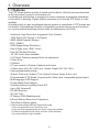
1. Overview
7
1 1 Features
1.2 System Configuration
1.3 Termination Settings
7
8
8
2. Installation and Connection
2.1 Package Contents
2.2 Installation
2.3 Connection Interface and Wiring Cables
2.4 Setting Dome Camera
3. Program and Operation
OSD Menu Structure
3.1 Getting Started
3.2 Main Menu
3.3 System Setup Menu
3.4 Display Setup Menu
3.5 Camera Setup Menu
3.6 Dome Motion Menu
3.7 Preset Menu
3.8 Pattern Menu
3.9 Tour Menu
3.10 Auto Scan Menu
3.11 Alarm Menu
9
9
10
11
12
13
13
16
17
17
19
22
25
27
28
29
30
31
4. Troubleshooting
32
5. Specifications
33
6. Dimensions
34
Appendix. Pelco Protocol Function List
35
Camera ID Chart
CAUT I O N
These servicing instructions are for use by qualified service personnel only.
To reduce the risk of electric shock do not perform any servicing other than
that contained in the operating instructions unless you are qualified to do so.
Use Class 2 Power Supply Only
2
Cautions
This device complies with Part 15 of the FCC Rules.
Operation is subject to the following two conditions;
1. This device may not cause harmful interference.
2. This device must accept any interference received, including
interference that may cause undesired operation.
Note
This equipment has been tested and found to comply with the limits for
a Class A digital device, pursuant to part 15 of the FCC Rules. These limits are
designed to provide reasonable protection against harmful interference when the
equipment is operated in a commercial environment. This equipment generates,
uses, and can radiate radio frequency energy and, if not installed and used in
accordance with the instruction manual, may cause harmful interference to radio
communications. Operation of this equipment in a residential area is likely to cause
harmful interference in which case the user will be required to correct the interference
at his own expense.”
WARNING
This is a class A product. In a domestic environment this product may cause radio
interference in which case the user may be required to take adequate measures.
Caution
Any changes or modifications in construction of this devices which are not expressly
approved by the party responsible for compliance could void the user’s authority to
operate the equipment.
CAUTION
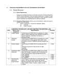
1. A regulated AC24V 2.5A(With Heater) power supply is recommended for use with
this camera for the best picture and the most stable operation. An unregulated
power supply can cause damage to the camera. When unregulated power supply
is applied, product warranty will be out of subject.
2. It is recommended that the camera is used with a monitor that has a CCTV quality
75 video impedance level. If your monitor is switched to high impedance then
please adjust accordingly.
3. Do not attempt to disassemble the camera to gain access to the internal
components. Refer servicing to your dealer.
4. Never face the camera towards the sun or any bright or reflective light, which may
cause smear on the picture and possible damage to the CCD.
5. Do not remove the serial sticker for the warranty service.
6. Do not expose the camera to rain or other types of liquid.
7. The apparatus must be connected to a mains socket-outlet with a protective
earthing connection.
3
Cautions
Correct Disposal of This Product
(Waste Electrical & Electronic Equipment)
(Applicable in the European Union and other European countries with
separate collection systems)
This marking shown on the product or its literature, indicate that it should not be
disposed with other household wastes at the end of its working life. To prevent
possible harm to the environment or human health from uncontrolled waste
disposal, please separate this from other types of wastes and recycle it responsibly
to promote the sustainable reuse of material resources.
This product should not be mixed with other commercial wastes purchased this
product, or their local government office, for details of where and how they can take
item for environmentally safe recycling.
Business users should contact their supplier and check the terms and conditions of
the purchase contract.
Household users should contact either the retailer where they for disposal.
CAUTION
RISK OF ELECTRIC SHOCK DO NOT OPEN
CAUTION: TO REDUCE THE RISK OF ELECTRIC SHOCK,
DO NOT REMOVE COVER (OR BACK).
NO USER. SERVICEABLE PARTS INSIDE.
REFER SERVICING TO QUALIFIED SERVICE
PERSONNEL
This symbol is intended to alert the user to the presence of uninsulated “dangerous voltage” within the product’s enclosure
that may be of sufficient magnitude to constitute a risk of electric
shock to persons.
This symbol is intended to alert the user to the presence of
important operating and maintenance (servicing) instructions in
the literature accompanying the appliance
4
IMPORTANT SAFETY INSTRUCTION
1)
Read these instructions.
2)
Keep these instructions.
3)
Heed all warnings.
4)
Follow all instructions.
5)
Do not use this apparatus near water.
6)
Clean only with dry cloth.
7)
Do not block any ventilation openings. Install in accordance with the
manufacturer’s instructions.
8)
Do not install near any heat sources such as radiators, heat registers,
stoves, or other apparatus (including amplifiers) that produce heat.
9)
Do not defeat the safety purpose of the polarized or grounding-type plug. A
polarized plug has two blades with one wider than the other. A grounding type
plug has two blades and a third grounding prong. The wide blade or the third
prong are provided for your safety. If the provided plug does not fit into your
outlet, consult an electrician for replacement of the obsolete outlet.
10) Protect the power cord from being walked on or pinched particularly at plugs,
convenience receptacles, and the point where they exit from the apparatus.
11) Only use attachments/accessories specified by the manufacturer.
12) Use only with the cart, stand, tripod, bracket, or table specified by the
manufacturer, or sold with the apparatus. When a cart is used,
use caution when moving the cart/apparatus combination to
avoid injury from tip-over.
13) Unplug this apparatus during lightning storms or when unused for long
periods of time.
14) Refer all servicing to qualified service personnel. Servicing is required when
the apparatus has been damaged in any way, such as power-supply cord or plug
is damaged, liquid has been spilled or objects have fallen into the apparatus, the
apparatus has been exposed to rain or moisture, does not operate normally, or
has been dropped.
5
1. Overview
1.1 Features
The PTZ Dome shall be quickly to install and be able to offer the services described
in this document by way of an interface unit.
Its mechanical architecture is designed to ensure adequate mechanical attachment
to the wall of a dwelling. Details shall be provided as to how the PTZ Dome is to be
installed.
A building block for any surveillance/security system is composed of PTZ domes and
Controllers. Extensible and flexible configuration promotes remote control functions
for various external switching devices such as multiplexers and DVRs
- Autofocus, High Resolution Integrated Color Camera
- 120X Zoom (12X Optical, 10X Digital )
- WDR (Wide Dynamic Range)
- BLC / HSBLC
- DNR (Digital Noise Reduction)
- Day & Night (Auto / BW / Color)
- Pan 360°Endless Rotation
- Tilt 180°Vector scan available
- 210 Preset Positions (except Short-cut command)
- 8 Auto Scan
- 6 Pattern
- 8 Tours consist of Presets, Patterns and Scans
- 4 Alarm Input (Off / NC / NO) and 1 Alarm Output (Off / NC / NO)
- User programmable setting
(Preset, Auto scan, Pattern, Tour, Home Function, Alarm Action, etc)
- Programmable PTZ Speed: Proportional to Zoom ratio, changeable preset speed
- Multi-language OSD Support
- Private Mask Zone Support
- Standard protocol including Pelco-D/P
- Up to 255 Camera ID
- RS-485 Receiver
- AC 24V Only
- IP Rating: IP66 (Weatherproof)
- HDcctv Alliance Base Line Compliance
- The HDcctv Alliance states.
- Look for the unique HDcctv logo to be sure.
• 100m transmissions over even to be sure.
• Plug-and-Play interoperability with other compliant products.
• Forward compatibility with future versions of the standard.
• See www.hidefcctv.org for details.
6
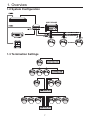
1. Overview
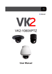
1.2 System Configuration
MULT IP LEXER
1.3 Termination Settings
7
2. Installation and Connection
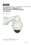
2.1 Package Contents
Camera
Wall Mount Bracket
Operation Manual
Screws/Plastic Anchors/Wrench/Washers
/Terminal(AC24V,RS485 and Alram)
Screws(4ea)
Washers(4ea)
Plastic
Anchors(4ea)
Terminal(AC24V)
Terminal(RS485)
Terminal(Alram)
L-wrench
8
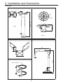
2. Installation and Connection
Unit: mm
Option - Ceiling Mount Bracket
.5
12
Ø
4-
Ø130
90
116
4-Ø
A-type
Approx. 80
Approx. 390
10
B-type
Option - Corner Mount
Option - Parapet Mount
628
91
0
15
128
1006
Option - Pole Mount
Strap Length 720
9
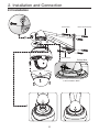
2. Installation and Connection
2.2 Installation
Screws(4ea)
Plastic anchors(4ea)
③
②
Washers(4ea)
Safety Wire
①
Connect the Camera Safety Wire
to the Installation Base.
10
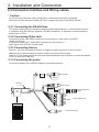
2. Installation and Connection
2.3 Connection Interface and Wiring cables
* Caution
Do not connect the power cable until all other connections have been completed.
After removing the protection sheet (PE form), supply the power to the dome camera.
2.3.1 Connecting the RS-485 lines
The dome camera can be controlled remotely by an external device or control system such as
a controller using RS-485 half duplexer (RS-485 Connection). A repeater is recommended to
extend over 1.2 Km.
2.3.2 Connecting Video Jack
Connect the video Jack (BNC connector) to the monitor or video input of the DVR.
(Video for HDcctv)
Connect the video Jack (Yellow BNC connector) to the monitor or
video input of the DVR for checking only
2.3.3 Connecting Alarms
Alarm In: You can use external devices to trigger the dome camera to react to events
Mechanical or electrical switches can be wired to the AI and Ground pins
Alarm Out: The dome camera can activate external devices such as buzzer. Connect the device
to NO (or NC) and COM pins.
2.3.4 Connecting the power
Connect the power jack of AC24V adaptor to the dome camera.
BNC Female
Alliance
Label
Bonding
Bonding
BNC Female
Caution
Label
Signal
Label
Terminal Block(2P)
AC24V
(Only AC24V)
NC
COM
NO
AL3
GND ALM
AL2
AL3
AL0
TRX +
TRX -
11
Terminal Block(8P)
Terminal Block(2P)
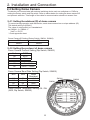
2. Installation and Connection
2.4 Setting Dome Camera
The device can communicate with external switching device such as multiplexer or DVRs by
setting the Rotary switch and Dip switch. Refer to tables below for setting the dome camera ID
and protocol selection. Total length of the cable for communication should not exceed 1km.
2.4.1 Setting the address (ID) of dome camera
To prevent wrong operation and malfunction, each dome camera has a unique address (ID).
The default setting is 0[ID001].
The value of rotary switch is in hexadecimal.
ex) SW301 : A, SW302 : F
0xAF => ID175
* Check appendix sheet
Dome Camera ID Setting (Rotary Switch, SW301, SW302)
X16
X1
SW301
SW302
2.4.2 Setting the protocol of dome camera
Dome Camera Protocol Setting (Dip Switch, SW303)
No1
CVBS
Off
On
NTSC
PAL
No2
Protocol
Off
On
Pelco D / P
Pelco P / Others
Dome Camera Baud Rate Setting (Dip Switch, SW303)
No3
No4
Baud
Rate(bps)
Off
Off
On
On
Off
On
Off
On
2400
4800
9600
38400
SW302
SW301
Dome Camera Termination Setting Off / ON
(NO5, Dip Switch, SW303)
12
SW303
3. Program and Operation
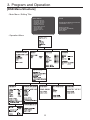
[OSD Menu Structure]
- Main Menu / Editing Title
MAIN MENU
TITLE
SYST EM SET U P
D I SPLAY SET U P
C AMER A SET U P
D O ME MO T I O N
PR ESET SET U P
PAT T ER N SET U P
T O U R SET U P
SC AN SET U P
ALAR M SET U P
EXI T
- Operation Menu
13
ABCDEFGHIJKLMNOPQRSTUVWXYZ
0123456789/+-=:?!#.,"~()
SELECT: (MOVE)
SET/CLEAR: (TELE/WIDE)
SAVE: (NEAR)
EXIT: (FAR)
3. Program and Operation
DOME MOTION SETUP
GENERAL SETUP
MOTION SETUP
HOME ACTION
CALIBRATION
EXIT
GENERAL SETUP
MOTION SETUP
HOME ACTION SETUP
CALIBRATION SETUP
POWER-UP ACT : ON
MANUAL SPEED : 100DEG
PRESET SPEED : FAST
PRESET FREEZE : OFF
PRO.PAN/TILT : ON
AUTO FLIP : ON
OVER TILT : MODE 1
ACTION : HOME
NUMBER :
TIME : 010 MIN
MODE : OFF
IN PRESET : DISABLE
AUTO CAL : AUTO
ERROR MSG DISP : ON
CALIBRATION
REFRESH MODE : OFF
REFRESH TIME :
SAVE : OPEN
BACK : CLOSE
SAVE : OPEN
BACK : CLOSE
SAVE : OPEN
BACK : CLOSE
SAVE : OPEN
BACK : CLOSE
CONTINUE?
YES : NEAR
NO : FAR
14
3. Program and Operation
This manual is designed to be a reference for the programming and operation of the system. You
can see information about features of the dome and commands as well as an operation method.
The symbols below mean some action of the joystick controller.
▲ / ▼: move joystick up and down
◀ / ▶: move joystick left and right direction
▶: select or change values
[Tele / Wide]: move joystick clockwise or counter-clockwise for zooming
[KEY]: press the defined key.
15
3. Program and Operation
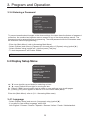
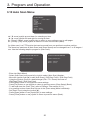
3.1 Getting Started
You should install and connect the dome to an interface device before using this operating guide.
Refer to {2. Installation and connection of this manual}.
Once installed, apply power to the dome and the start-up screen is displayed on the monitor.
X12 M INI SPEED DOM E
V x.xx.xx
RS485/2400
1080P 30HZ
ID001
CAM TEST ...PASS
Before installing and operating the dome camera, please read this user’s manual carefully.
This dome camera can be operated using two methods:
- Use hot keys [Refer to Appendix].
- Use OSD Menu on the monitor [Read this operation manual].
* Notice: You shall check the saving state of each step at sub menu or edit menu, after editing
functions or changing settings. You may save setting one function twice. For example, after {the
position or title of Preset} is saved at ‘Sub Menu’, {the status of Preset Setup} has to be saved at ‘Preset
Setup Menu’ again.
* Notice: To stop an action, press [ESC] button or [96+Preset]. In that case, the dome goes to
manual mode or is to be paused temporarily (about 10sec in Alarm mode)
3.1.1 ACCESSING MAIN MENU [95] + [Preset]/ [Menu]
When you use Pelco-D and Pelco-P protocol with your controller, you can access to the main
menu on your monitor by pressing the key [95] + [Preset] or pressing and holding the
[Menu] key for 2 seconds.
3.1.2 Editing TITLE
TITLE
ABCDEFGHIJKLMNOPQRSTUVWXYZ
0123456789/+-=;?#.,"~0
SELECT : (MOVE)
SET/CLEAR: (TELE/WIDE)
SAVE : (NEAR)
EXIT : (FAR)
The title edit menu can be used in the setup for Preset / Pattern / Tour / Scan commonly.
- Move the joystick right in Main Menu. The screen appears on the monitor:
- Move the joystick right, left, up or down to select a character.
- Press [Tele] button to input a character and [Wide] button to cancel the character.
- When the label is completed, use [Near] or move the joystick to save the selected title.
- If you want to cancel the selected title, return to the previous menu using [Far] button.
16
3. Program and Operation
3.2 Main Menu
MAIN MENU
SYST EM SET U P
D I SPLAY SET U P
C AMER A SET U P
D O ME MO T I O N
PR ESET SET U P
PAT T ER N SET U P
T O U R SET U P
SC AN SET U P
ALAR M SET U P
EXI T
▲ / ▼: move joystick up and down for selecting an item.
◀ / ▶: move joystick left and right for moving an item.
▶ / [Open] / [Near]: move joystick right to select or save values or go to edit pages.
▶ / [Close] / [Far]: move joystick to cancel or to exit current menu.
(Back to previous menu without saving)
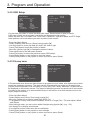
3.3 System Setup Menu
SYSTEM SETUP
INFO.
R EBO O T
I N I T I ALZ E
PASSWO R D
EXI T
▲ / ▼: move joystick up and down for selecting an item.
◀ / ▶: move joystick left and right for moving an item.
▶ / [Open] / [Near]: move joystick right to select or save values or go to edit page.
▶ / [Close] / [Far]: move joystick to cancel or to exit current menu (back).
3.3.1 System Information
SYSTEM INFORMATION
X12 MI N I SPEED D O ME
V x. xx. xx
R S485/ 2400
1080P 30H Z
I D 001
-EXI T : (F AR )
The system Information displays model name / Running Version / Protocol / Communication
Type / Camera ID No. / System. It is read only for reference. Use the following steps to display
the System Information screen: Camera ID changes with respect to ID switching setting
- Enter into {Main MENU}
- Select {System} using the joystick [▶].
- Move the joystick right [▶] for selecting {Info} in the sub menu of {System}.
- Press [Far] button or use joystick [▶] to return to previous menu (Back).
17
3. Program and Operation
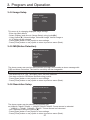
3.3.2 Reboot
REBOOT
C O N T I N U E?
YES : N EAR
N O : F AR
Reboot the system if there are some anomalous problems to control or operate the domes.
Rebooting the system will recycle power of dome and camera without changing settings of dome.
- Enter into {Main Menu}
- Select {System) using joystick and move to {Reboot} in the sub menu of {System}
- To {Reboot} the system, Press [Near] key.
- To cancel Reboot, Press [Far] key.
3.3.3 Initialize
INITIALIZE
ALL
:
C AM :
PR ESET :
TOUR
:
PAT T ER N :
SC AN :
ET C :
SAVE
BAC K
NO
NO
NO
NO
NO
NO
NO
C LR
C LR
C LR
C LR
C LR
C LR
C LR
: O PEN
: C LO SE
Use this function to initialize all or specific parameters of dome to factory default parameters.
- Enter into {Main Menu}
- Select {System} using joystick [▶] and move to {Initialize} in the sub menu of {System}
- Select items to be initialized.
- Press [Near] button or use joystick [▶] to select {Clear}
- Press [Far] button or use joystick [▶] to return to previous menu (back).
[ALL]: Clear All saved items (CAM / PRESET / TOUR / PATTERN / SCAN)
[CAM]: Clear Camera related settings.
[PRESET]: Clear saved presets. (To clear each preset, refer to PRESET Menu)
[TOUR]: Clear saved Tours.
[PATTERN]: Clear saved Patterns.
[SCAN]: Clear saved Scan items.
[ETC]: Clear other setting value except items of Camera & PTZs
(CAM status and saved data of PRESET, TOUR, PATTERN and SCAN)
18
3. Program and Operation
3.3.4 Entering a Password
PASSWDRD
C U R R EN T :
EN ABLE :
N EW
:
C O N F I R M :
...
D I SABLE
...
...
0123456789
-SET / C LEAR : (T ELE/ WI D E)
-EXI T : (F AR )
To prevent unauthorized changes to the dome settings, the dome have the feature of password
protection. An unauthorized operator cannot access to any of the dome settings menus. The
password must be entered before programming. The valid password with four characters must
be entered to continue programming.
- Enter into {Main Menu} (refer to Accessing Main Menu)
- Select {System} and move to {Password} in the sub menu of {System} using joystick [▶].
- Select numbers using joystick left / right and press [Tele] key.
- To lock the password, set Enable: Enable
* Note: 0000 is the default password.
3.4 Display Setup Menu
DISPLAY SETUP
OSD SETUP
PRIVACY ZONE SETUP
IMAGE SETUP
MOTION
RESOLUTION
LANGUAGE : ENGLISH
EXIT
▲ / ▼: move joystick up and down for selecting an item.
◀ / ▶: move joystick left and right for moving an item.
▶ / [Open] / [Near]: move joystick right to select or save settings or go to edit pages.
▶ / [Close] / [Far]: move joystick to cancel or to exit current menu (Back).
Enter into {Main Menu}: refer to {3.1.1 Accessing Main menu}.
3.4.1 Language
- Select {Display Setup} and move to {Language} using joystick [▶].
- If you want to use another language, select one
from English / Chinese / Russian / Spanish / German / Italian / French / Netherlandish.
19
3. Program and Operation
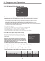
3.4.2 OSD Setup
OSD SETUP
- T I T LE
LA B E L P O S I T I O N : O F F
T I ME : ON
Z O O M
: OFF
ID
: ON
MO D E : ON
A N G LE : 3SEC
SAVE
: O PEN
BACK
: C LO SE
- CHANGE
: ( LE F T / R I G H T )
- TO SETUP
: ( TELE)
ER O O R MSG
- EXI T : F AR
ZOOM
- MO D E - D T I ME - ID - AN G L E -
You can see only video or some character with video. Each element is able to handle.
OSD setup allows you to program how labels are displayed on the monitor.
Labels are such as Title, Dwell Time, Zoom ratio, Camera ID, Operation Mode and PTZ Angle
Label position can be set where you want to place on the monitor.
- Enter into {Main Menu}
- Select {Display} and move to {Setup} using joystick [▶]
- Use the joystick to move the label up, down, left, and/or right.
- Press [Tele] button to edit the position of labels.
- Move the joystick right [▶] to change the status of labels.
- Other labels can be set with same method.
- Press [Far] button to return the previous menu (OSD setup).
- Press [Open] button or use joystick to save the status.
- Press [Close] button or use joystick to return to previous menu (Back).
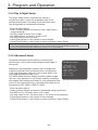
3.4.3 Privacy zone
PRIVACY ZONE SETUP
PRIVACY ZONE SETUP
P R I V A C Y . 00 : N O T U SED
EDIT
:
D I S P LA Y :
WIDTH
:
HEIGHT
:
C LE A R
PR ESS MO VE KEY
SAVE : N EAR
EXI T : F AR
SAVE : OPEN
B A C K : C LO S E
- C H A N G E : ( LE F T / L I G H T )
A Private mask zone allows an administrator to program one four-sided, user defined zone which
cannot be viewed by operators. The mask can be changed with pan angle and tilt angle using
joystick and be adjusted in size according to zoom ratio [Tele / Wide]. Maximum 15 positions can
be displayed on the monitor screen. The speed of displaying masks is proportional to the number
of masks on the screen. It is recommended that you set the size to at least twice the size of the
object (height and width)
- Enter into {Main Menu}
- Select Display and Privacy Zone using joystick [▶].
- Move the joystick left or right to select zone ID[00~14].
- To program a Privacy Zone, select Edit Mask, move to a Target (Pan / Tilt) and adjust a Mask
size (Zoom).
- After editing a mask, you can re-size width & height using joystick [▶]. (e.g. ~5X)
- Set display On to display saved mask.
- It is possible to clear saved zone No.xx individually.
- Press [Open] button or use joystick to save settings.
- Press [Close] button or use joystick to return to previous menu (Back).
20
3. Program and Operation
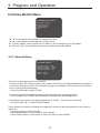
3.4.4 Image Setup
IMAGE SETUP
MI R R O R : N O R MAL
SAVE
BAC K
: O PEN
: C LO SE
This menu is for changing displayed image settings.
- Enter into {Main Menu}
- Select {Display} and move to {Image Setup} using joystick[▶].
- Using joystick [▶], Normal image, Horizontal image, Vertical image or
H / V image can be selected.
- Press [Open] button or use joystick to save settings.
- Press [Close] button or use joystick to return to previous menu (Back).
3.4.5 MD(Motion Detection)
MOTION DETECTION
MD : O F F
SEN SI T I VI T Y :
ALAR M :
AT I ME :
SAVE
BAC K
: O PEN
: C LO SE
The dome camera can monitor the movement of image, and it sends an alarm message with
OSD and Alarm Out action. The level for sensitivity can be changeable.
* Note: To stop alarming temporarily (about 10sec), press [ESC] button or [96+preset].
- Set sensitivity for 0~100. The higher value, the more sensitive.
- Set alarm mode for OSD/Alarm out/Both using joystick.
- Press [Open] button or use joystick to save settings.
- Press [Close] button or use joystick to return to previous menu (Back).
3.4.6 Resolution Setup
RESOLUTION SETUP
R ESO LU T I O N : 1080P30H z
SAVE
BAC K
: O PEN
: C LO SE
The dome camera can be rebooted by resolution set.
ex)1080p30,720p60,720p30 -> 1080p25,720p50,720p25 : Dome camera is rebooted.
1080p30 -> 720p60 , 1080p25->720p50 : Dome camera isn't rebooted.
- Set a Resolution using the joystick [▶].
- Press [Open] button or use joystick to save settings.
- Press [Close] button or use joystick to return to previous menu (Back).
21
3. Program and Operation
3.5 Camera Setup Menu
CAMERA SETUP
F O C U S/ Z O O M
W-BALAN C E
EXPO SU R E
D AY/ N I G H T
AD VAN C ED
EXI T
▲ / ▼: move joystick up and down for selecting an item.
◀ / ▶: move joystick left and right for moving an item.
▶ / [Open] / [Near]: move joystick right to select or save settings or go to edit pages.
▶ / [Close] / [Far]: move joystick to cancel or to exit current menu (Back).
3.5.1 Focus / Zoom
FOCUS/ZOOM SETUP
F O C U S
: AU T O
Z O O M SPD : F AST
D . Z O O M
: OFF
SAVE
BAC K
: O PEN
: C LO SE
Auto Focus allows the lens to remain in focus during zoom-in, zoom-out and motion functions
automatically.
Zoom speed allows the user to define how fast the dome will go from full wide zoom to the 12X
optical zoom. There are four modes (Slow, Normal and Fast).
And the default setting is ‘Fast’.
D.Zoom allows the user to use Digital Zoom. Default setting is Optical Zoom without Digital Zoom.
- Enter into {Main Menu}
- Select {Camera Setup} and move to {Focus/Zoom} using joystick[▶].
- Set Focus mode for Auto or Manual.
- Set Zoom Speed for Fast, Normal or Slow.
- Select On / Off to set a status of D.Zoom.
- Press [Open] button or use joystick to save settings.
- Press [Close] button or use joystick to return to previous menu (Back).
22
3. Program and Operation
3.5.2 WB Setup (White Balance Setup)
WB SETUP
MO D E
R G AI N B G AI N : AWB
:
:
SAVE
BAC K
: O PEN
: C LO SE
This feature automatically processes the viewed image to retain color balance over a color
temperature range.
In Manual mode, you can change the R or B gain value to adjust the color on a monitor.
* Auto Trace White balance (ATW): It aligns the white balance automatically. (2,300 to 11,000 K)
* Indoor : 3200K Base Mode. Red and Blue gain value can be set by user, 0~255.
* Outdoor : 5400K Base Mode. Red and Blue gain value can be set by user, 0~255.
* Push WB mode: The white balance is aligned during key input. (White balance push auto key)
* Auto White Balance mode (AWB): Wide range auto white balance mode. In this mode, the white balance is
performed at a faster operating speed than ATW.
- Enter into {Main Manu}
- Select {Camera Setup} and move to {WB Setup} using joystick[▶].
- Set WB mode for ATW, Indoor, Outdoor, Onepush or AWB.
- Press [Open] button or use joystick to save settings.
- Press [Close] button or use joystick to return to previous menu (Back).
3.5.3 AE Setup (Auto Exposure Setup)
Sharpness enhances picture detail by increasing the
aperture gain of the camera and sharpening the edges
in the picture.
AE SETUP
MODE : F UL L A UTO
SHUT :
AGC GAI N :
MAX DSS : O FF
BRI GHT : 0 3 0
When both high-brightness subjects and low-brightness
subjects have been shot at the same time, overexposure
SAVE : OP E N
in the high-brightness subjects or loss of dark detail in the
BACK : CL O S E
low-brightness subjects may occur.
The WDR (Wide Dynamic Range) function creates images
free from overexposure or loss of dark detail by combining
two images after tripping the shutter for a long exposure time and for a short exposure time in
one field.(One mode can be selected from BLC / WDR / HSBLC / DNR)
- Enter into {Main Manu}.
- Select {Camera Setup} and move to {AE Setup} using joystick[▶].
- Set AE mode for Full Auto, Manual, Shutter PRI.
- Press [Open] button or use joystick to save settings.
- Press [Close] button or use joystick to return to previous menu (Back).
AE Mode
Full Auto
Manual
SHUT FIX
Shutter(Auto, X2 ~ X64, 1/30(1/25)~1/10000)
X
O (Auto)
O (Auto)
AGC Gain(OFF, Low / Mid / High)
X
O (Mid)
X
DSS(OFF, X2 ~ X64)
O (x2)
X
X
Bright(0~100)
O (30)
O (30)
O (30)
23
3. Program and Operation
3.5.4 Day & Night Setup
The Day & Night function improves the camera’s
sensitivity at night or when the brightness level of the
ambient environment. According to the luminance level,
Day & Night filter is automatically switched.
D/N SETUP
D AY/ N I GH T : A U T O
D / N D ETE C T : V ID E O
D / N D T I M E : 0 3
- Enter into {Main Manu}
SAVE : O P E N
BAC K : C L O S E
- Select {Camera Setup} and move to {Day / Night Setup}
using joystick [▶].
- Set Day / Night for Auto, Day or Night.
- Set D&N Detector for Sensor, Video or EXT.
- Set switching time that you want.
- Press [Open] button or use joystick to save settings.
- Press [Close] button or use joystick to return to previous menu (Back)
* Notice:
If you connect Digital Input signal (High or Low) to the terminal of AL3 and set EXT in this menu,
you can use EXT D/N instead of Alarm Input. [Refer to 3.11 Alarm Menu]
3.5.5 Advanced Setup
Sharpness enhances picture detail by increasing the
aperture gain of the camera and sharpening the edges in
the picture.
When both high-brightness subjects and low-brightness
subjects have been shot at the same time, overexposure
in the high-brightness subjects or loss of dark detail in the
low-brightness subjects may occur.
The WDR (Wide Dynamic Range) function creates images
free from over-exposure or loss of dark detail by combining
two images after tripping the shutter for a long exposure time
and for a short exposure time in one field.(One mode can be
selected from BLC /WDR / HSBLC / DNR)
ADVANCED SETUP
SH AR PN E S S : 5 0
BLC LEVE L : O F F
WD R LEV E L : O F F
H SBLC L E V E L : O F F
D N R LEVE L : O F F
SAVE : OP E N
BAC K : CL O S E
- Enter into {Main Manu}
- Select {Camera Setup} and move to {Advanced} using joystick [▶].
- Set WDR for On / Off and a level in ‘On’ mode.
- Set other mode for On / Off and a level in ‘On’ mode in the same way.
- Press [Open] button or use joystick to save settings.
- Press [Close] button or use joystick to return to previous menu (Back).
24
3. Program and Operation
3.6 Dome Motion Menu
DOME MOTION SETUP
G EN ER AL SET U P
MO T I O N SET U P
H O ME AC T I O N
C ALI BR AT I O N
EXI T
▲ / ▼: move joystick up and down for selecting an item.
◀ / ▶: move joystick left and right for moving an item.
▶ / [Open] / [Near]: move joystick right to select or save settings or go to edit pages.
▶ / [Close] / [Far]: move joystick to cancel or to exit current menu (Back).
3.6.1 General Setup
GENERAL SETUP
PO WER -U P AC T . : O N
MAN U AL SPEED : 100D EG
PR ESET SPEED : F AST
PR ESET F R EEZ E : O F F
SAVE : O PEN
BAC K : C LO SE
This menu control general function of dome.
Power-up Action is a function (preset, tour, pattern and scan) to be performed when the power is
re-cycled or after alarm action. The following settings are available. Set the dome ‘On’ to resume
its prior activity.(Recommended)
- Use the joystick [▶] to select On/Off
You can change pan/tilt speed for manual operation with the manual speed item.
- Use the joystick [>] to select speed between 100degree/sec and 20degree/sec.
Preset Speed is possible to set preset speed with 3 options. : Fast, Normal, and Slow.
- Use the joystick [▶] to select {Preset Speed}
Preset freeze is a function to freeze the image while moving to specific preset from the view you
watch out.
- Use the joystick[>] to select On/Off
- Press [Open] button or use joystick to save settings.
- Press [Close] button or use joystick to return to previous menu (Back).
25
3. Program and Operation
3.6.2 Motion Setup
MOTION SETUP
PR O P. PAN / T I LT
AU T O F I LP
O VER T I LT
: ON
: ON
: MO D E 1
SAVE : O PEN
BAC K : C LO SE
Proportional Pan / Tilt is possible to set manual speed with Zoom
- Use the joystick [▶] to select On/Off
Auto-Flip is a function automatically reversing the image when zoom module camera passes
through the top of tilt direction (90 degree)
When tilt angle arrives at the top of tilt orbit (90degree), zoom camera module keep moving to
opposite direction of tilt to keep tracking targets. As soon as zoom camera module passes through
the top of tilt direction (90degree), image should be reversed automatically.
- Use the joystick [▶] to select On / Off
Over-Tilt is for restricting vertical view angle related to the operation range of IR sensor and some
blocking view angle mechanically.
To prevent horizontal view cut with tilt angle(with window bubble), it is to restrict vertical view
angle in each mode.
- Use the joystick [▶] to select Mode 0 / Mode 1 / Mode 2
3.6.3 Home Action Setup
HOME ACTION SETUP
AC T I O N N U MBER T I ME
MO D E
I N PR ESET
:
:
:
:
:
H O ME
010 MI N
OFF
D I SABLE
SAVE : O PEN
BAC K : C LO SE
Home Action can be set so that the dome automatically goes to a preset, a tour or auto scan after
the joystick control has been idle for some amount of time.
The dwell time can be set from 1 minute to 60 minutes.
- Using the joystick [▶], {Home Action} can be selected to Home, Preset, Scan and Tour.
- {Number} is the number of {Action}. For example, {Action: Preset/Number: 001} mean Preset [1]
- Set {Time} xx min using the joystick [▶].
- Using the joystick [▶] to select Auto(On) / Manual (Off).
- If you want to do the funtion in excuting preset, you can set enable.
- Press [Open] button or use joystick to save settings.
- Press [Close] button or use joystick to return to previous menu {Dome Motion Setup} (Back).
* Note: In order to call an action (Preset, Pattern, Tour or Scan), you must save Preset, Pattern, Tour,
or Scan first.
26
3. Program and Operation
3.6.4 Calibration Setup
CALIBRATION SETUP
CONTINUE?
A U T O C A L : A U T O
E R R O R MS G D I SP : O F F
C A LI B R A T I O N
R E F R E S H MO D E : O F F
R E F R E S H T I ME :
YES : N EAR
N O : F AR
SAVE : OPEN
B A C K : C LO S E
- Set calibration mode for Manual / Auto using the joystick [▶].
- In manual mode, select {Calibration} to execute {Calibration} using the joystick[▶],
and press [Near] button or use joystick to continue.
- Set {Error Message Display} for On / Off using the joystick [▶].
Refresh is a function that calibrates P/T/Z regularly.
- Using the joystick [>] to select on/off
- Using the joystick [>] to select time from 3 hours to 7 days every 3 hours.
- Press [Open] button or use joystick to save settings.
- Press [Close] button or use joystick to return to previous menu (Back).
* Note: {Calibration} is a function for correcting an error on the angle of Pan / Tilt automatically.
{Calibration} can be set for Manual/Auto. In Manual mode, if there is an error on the angle of the
dome, execute {Calibration} using the joystick [▶]. Press [Near] button to continue calibration
or press [Far] button to cancel calibration.In Auto mode, when there is an error on the angle of
the dome, the dome is corrected automatically. The motor of the Pan / Tilt will adjust its angle
automatically. {Error Message Display} is a function for displaying an error message to let a user
know {Sensing error} on the monitor.
3.7 Preset Menu
PRESET SETUP
N O . 001
ED I T T I T LE
D T I ME
C LEAR
: N O T U SED
:
:
:
SAVE : O PEN
BAC K : C LO SE
▲ / ▼: move joystick up and down for selecting an item.
◀ / ▶: move joystick left and right for moving an item.
▶ / [Open] / [Near]: move joystick right to select or save settings or go to edit pages.
▶ / [Close] / [Far]: move joystick to cancel or to exit current menu (Back).
27
3. Program and Operation
The dome has maximum 210 preset positions. Each of the user-defined presets includes
Pan / Tilt / Zoom. Use the following steps to program {Preset}.
PRESET SETUP
PR ESS MO VE KEY
SAVE : N EAR
BAC K : F AR
- Enter into {Main Manu}
- Select {Preset} and Move left or right to select Preset Number.
- Move the joystick right [▶] to edit a {Preset}
- Using the joystick, move to a desired target (Pan / Tilt / Zoom)
- Press [Near] button or use joystick to save settings.
- Press [Far] button or use joystick to return to previous menu {Preset Edit} (Back).
- To edit and clear the {Preset Title}, refer to Editing a Title section (3.2.1).
- It is possible to clear saved Preset No.xxx in the {Preset Setup Menu} individually.
- Set {Dwell Time} using the joystick [▶]
- Press [Open] button or use joystick to save settings.
- Press [Close] button or use joystick to return to previous menu (Back).
3.8 Pattern Menu
PATTERN SETUP
N O . 001 : N O T U SED
ED I T
:
T I T LE
:
T I ME
:
C LEAR
SAVE : O PEN
BAC K : C LO SE
▲ / ▼: move joystick up and down for selecting an item.
◀ / ▶: move joystick left and right for moving an item.
▶ / [Open] / [Near]: move joystick right to select or save settings or go to edit pages.
▶ / [Close] / [Far]: move joystick to cancel or to exit current menu (Back).
A {Pattern} is to display (or recall) a memorized, repeated and serial trace of pan, tilt, zoom.
The dome has maximum 8 {Patterns}. Each of the user-defined scans includes Pan / Tilt / Zoom.
28
3. Program and Operation
Use the following steps to program {Pattern}.
PTIME: 022
START POSITION SETUP
PATTERN SETUP
PR ESS MO VE KEY
ST AR T : (N EAR )
SAVE : (N EAR )
EXI T : (F AR )
- Enter into {Main Manu}
- Select {Auto Scan} and move left or right to select {Pattern} Number.
- Move the joystick right [▶] to edit {Pattern}
- Using the joystick, move to a desired target and press [Near] button to start programming {Pattern}
- Press [Near] button or use joystick to save settings.
- Press [Far] button or use joystick to return to previous menu {Pattern Setup} (Back).
- To edit and clear {Pattern Title}, refer to Editing a Title section (3.2.1).
- It is possible to clear saved Pattern No.xxx in the {Pattern setup} Menu individually.
- Press [Open] button or use joystick to save settings.
- Press [Close] or use joystick to return to previous menu (Back).
3.9 Tour Menu
TOUR SETUP
N O . 001 : N O T U SED
... ... ... ... ... ... ...
... ... ... ... ... ... ...
... ... ... ... ... ... ...
... ... ... ... ... ... ...
C LEAR
SAVE : O PEN
BAC K : C LO SE
- C H AN G E I D : (T ELE/ WI D E)
- C H AN G E AC T I O N : (N EAR )
▲ / ▼: move joystick up and down for selecting an item.
◀ / ▶: move joystick left and right for moving an item.
▶ / [Open] / [Near]: move joystick right to select or save settings or go to edit pages.
▶ / [Close] / [Far]: move joystick to cancel or to exit current menu (Back).
The dome can have 8 {Group Tours}. And each of the tour has 28 items.
Each item has pre-defined preset, pattern, and scan.
* Notice: In order to call an action (Preset, Pattern or Scan), you must save Preset, Pattern, or Scan first.
- Enter into {Main Manu}
- Select {Tour} and Move left or right to select {Tour} Number.
- Using the joystick [▲ / ▼ / ◀ / ▶], move to each item.
- Select an action/number (PRESET, TOUR, PATTERN and / or SCAN), with [Tele] button or
clear item with [Wide] button and change mode using [Near] button.
- It is possible to clear saved Tour No.xxx in the {Tour Setup Menu} individually.
- Press [Open] button or use joystick to save settings.
- Press [Close] button or use joystick to return to previous menu (Back).
29
3. Program and Operation
3.10 Auto Scan Menu
SCAN SETUP
N O . 001
: N O T U SED
ED I T :
SPEED :
D T I ME
:
D I R EC T I O N :
MO D E
:
C LEAR
SAVE : O PEN
BAC K : C LO SE
▲ / ▼: move joystick up and down for selecting an item.
◀ / ▶: move joystick left and right for moving an item.
▶ / [Open] / [Near]: move joystick right to select or save settings or go to edit pages.
▶ / [Close] / [Far]: move joystick to cancel or to exit current menu (Back).
An {Auto scan} is a PTZ function that can be moved from one position to another position.
The dome has maximum 8 {Auto Scan} and {Scan Speed} can be changed from 1 to 35 degree /
sec. Use the following steps to program a {Auto Scan}.
START POSITION SETUP
STOP POSITION SETUP
P R E S S MO V E K EY
PR ESS MO VE KEY
SAVE : (NEAR)
BACK : (FAR)
SAVE : (N EAR )
BAC K : (F AR )
- Enter into {Main Manu}
- Select {Auto Scan} and move left or right to select {Auto Scan} Number.
- Move the joystick right [▶] to edit {Auto Scan}: {Edit Start Point} / {Edit Stop Point}
- Using the joystick, move to a desired target (Pan / Tilt / Zoom) at screen of
{Edit Start Point} / {Edit Stop Point}
- Press [Near] button or use joystick to save settings.
- Press [Far] button or use joystick to return to previous menu {Scan Setup} (Back).
- To edit and clear the {Scan Title}, refer to Editing a Title section (3.2.1).
- It is possible to clear saved Scan No.xxx in the {Scan setup} Menu individually.
- Set {Dwell Time} using the joystick [▶].
- Press [Open] button or use joystick [▶] to save settings.
- Press [Close] button or use joystick to return to previous menu (Back).
30
3. Program and Operation
3.11 Alarm Menu
ALARM SETUP
N O . 001
: N O T U SED
IN
:
OUT
:
PR I O R I T Y :
AC T I O N :
N U MBER :
D T I ME
:
SAVE : O PEN
BAC K : C LO SE
- SET / C LEAR : (T ELE/ WI D E)
▲ / ▼: move joystick up and down for selecting an item.
◀ / ▶: move joystick left and right for moving an item.
▶ / [Open] / [Near]: move joystick right to select or save settings or go to edit pages.
▶ / [Close] / [Far]: move joystick to cancel or to exit current menu (Back).
- Enter into {Main Menu}
- Using the joystick [▶], select Alarm Input type (NO / NC).
- Using the joystick [▶], select Alarm Output (On / Off)
- Alarm priority can be set using the joystick [▶],
Change an action / number {Off, Preset, Pattern, Scan, or Tour}.
- Set Alarm action time (Dwell Time): 3~60sec / On, default setting is ‘ON’.
-> Time Out (3~60sec): This is activated during a period of a selected dwell
time when an alarm is triggered.
-> Momentary (On): When an alarm is triggered, the dome camera will
maintain alarm activation continuously, until it is stopped manually
(96+preset or / and changing in alarm menu).
- It is possible to clear saved {Alarm No.xxx}, pressing [Wide] button at a position of
{No.xxx} individually.
- Press [Open] button or use joystick [▶] to save settings.
- Press [Close] button or use joystick to return to previous menu (Back).
* Notice:
In order to call an action (Preset, Pattern, Tour or Scan), you must save Preset, Pattern, Tour, or
Scan first. To pause alarming (about 10sec) temporarily, press [ESC] button or [96+preset].
* Notice:
The dome camera normally supports 4 Alarm Input (AL0~3). But AL3 can be used as Digital input
for External D/N, so, in this case, Only AL0~2 are available for Alarm inputs.
31
4. Troubleshooting Guide
If problems occur, check the installation of the dome with the instructions in this manual.
And refer to this manual for further information.
Pr o b l e m
No video on the screen
Poor video quality.
Dome camera is not
working properly
(including wrong position of
dome camera)
So lu t io n
- Verify that power is connected to all components in the system.
- Verify that the power switches are ON.
- Verify the status of cables or connection of cables
- Check the power supply voltage (normal 24VAC)
- Check the setting of camera.
- If the lens or the dome is dirty, clean up the dome windows with
a clean cloth.
- Re-cycle the power supply re-connecting the power code.
Or reset the dome camera using the Dome configuration menus.
[Main > System > Reboot]
- Check that the connection of power cable and assembling status
of dome camera.
- Initialize the dome camera. [Main > System > Initialize]
- Check that RS-485 communication cable is not connected
The communication between
correctly. [Refer to 2.3 Connection Interface and Wire cables]
controller and cameras
- Check ID/Protocol/Baud rate / Termination Setting.
is not working properly.
[2.4 Setting Dome Camera]
(via 485 cable lines)
- See the configure of [1.3 Termination Settings]
The surface of the
dome case is hot.
The image on the
screen is flickers
The PTZ is calibrated
without user control.
- Check the voltage level of the dome camera and the assembling
status of dome camera.
- Check that the dome camera is connected to the proper power.
- Does the camera face directly into the sun or fluorescent lamp?
If so, reposition the dome. Check for flicker-less setting of the
dome.
- The PTZ will be back on the original position as tuned after
12 hours automatically
- It will prevent an errors by unexpected shock.
32
5. Specifications
Image Device
1/3" CMOS
Effective Pixels
About 2.1Mega Pixel
HD: 1920*1080(Full HD, 1080p @30fps,25fps)
1280*720(HD, 720p @60fps,50fps,30fps,25fps)
SD: NTSC, PAL
12X Optical /10X Digital Zoom (Auto Focus)
Approx.52.4° (Wide end) to 4.64° (Tele end)
0.1 Lux
On / Off
3DNR
Max. 8 zones
HD-SDI, CVBS Output
Video Signal
Lens
View Angle Approx.
Min. illumination
WDR
DNR
Privacy Masking
Video Output
Electrical
Power Supply
AC24V (±10%) Normal, Built-in Power Line Surge
Power Requirement
AC24VAC, 48W (with Heater)
Power Consumption
Maximum 25W (without Heater)
Alarm Output
1 Normal Relays 12VDC / 500mA Max (Selectable NC / NO)
Alarm Input
4 Normal Dry Contact (Selectable NC / NO)
Control
RS-485 baud rate: 2400~38.4Kbps (default: 2400bps)
Access Time
ID (Camera Address)
Mechanical
Weight
Dimension
Pan Angle
Tilt Range
Speed
0.75 second maximum preset recall time
Physical 255
360° Continuous rotation
0 ~ 180°
Maximum Preset Speed: 360°/sec
Flip
Rotate 180° at bottom of tilt
Auto Scan
8 Auto Scan include vector scan
Preset Position
210 Position with camera status
Tour
Pattern
On Screen Display
8 Tour (Preset, Pattern, Scan)
6 Pattern
Display camera ID, Title, Mode, and Angle on screen(Multi-Language)
English, Chinese, Russian, Spanish,
German, Italian, French, Netherlandish
Multi-language OSD
Environment
Certification
Operating Temperature
Heater(Bult-in)
Operating Humidity
Storage Temperature
IP Rating
3.5kg (with wall mount)
Ø166 x 341mm x 255mm (Bubble Dome Ø112)
CE / FCC / IP66 / HDcctv Alliance Base-Line Compliance
14°F ~ 122°F(-10 ~ +50°C)
Heater On: -4°F ~ 122°F(-20°C ~ +50°C)
On / Off: 0~10°C
80% RH
-4°F ~ 140°F(-20°C ~ 60°C / ~90%)
IP66 (Weatherproof)
Specifications and designs are subject to change for improving the functionality of this product without notice.
33
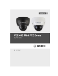
6. Dimensions
[Unit: mm]
341.2
254.9
140
161
258
Ø112
Ø120
Ø166.4
Ø138.4
0°
12
34
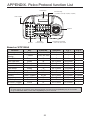
APPENDIX. Pelco Protocol function List
LCD Display
Function Keys
> F1(PSET), F2(TOUR), F3(PATT), F4(SCAN)
ESC / Power
Joystick
Number
Controller
Function Keys
Camera Focus Control
> NER / FAR, TELE / WIDE
Based on WTX1200A
Function
Preset
Preset Shortcut
Saving
Run PAN
Run PAN Zero
Scan Setup
Scan
Tour Setup
Tour
Pattern Setup
Pattern
Menu Key
ESC Key
D. Zoom (Toggle)
Key
Preset
Preset No.
1~59, 101~253
Operation
No.+Preset
e.g. 1
1+Preset
e.g. 2
-
* Preset
1~59, 101~253
*
*
-
Preset
Preset
Preset
Preset / Scan
Preset
Preset / Tour
Preset
Preset / Pattern
Preset / **Menu
Preset
Preset
33
34
60
61~68
70
71~78
80
81~88
95
96
97
No.+Preset
No.+Preset
No.+Preset
No.+Preset
No.+Preset
No.+Preset
No.+Preset
No.+Preset
No.+Preset
No.+Preset
No.+Preset
33+Preset
34+Preset
60+Preset
61+Preset
70+Preset
71+Preset
80+Preset
81+Preset
95+Preset
96+Preset
97+Preset
1+Scan
1+Tour
1+Pattern
**Menu
-
* Note:
- To save position of the dome, Press desired number of preset and hold [PRESET] key for 2 seconds.
- To go to OSD Main Menu, Press and hold [MENU] key for 2 seconds.
35
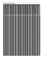
Camera ID Chart
ID
S301
S302
ID
S301
S302
ID
ID
S301
S302
ID
S301
S302
1
0
1
52
3
4
103
S301 S302
6
7
154
9
A
205
C
D
2
0
2
53
3
5
104
6
8
155
9
B
206
C
E
3
0
3
54
3
6
105
6
9
156
9
C
207
C
F
4
0
4
55
3
7
106
6
A
157
9
D
208
D
0
5
0
5
56
3
8
107
6
B
158
9
E
209
D
1
6
0
6
57
3
9
108
6
C
159
9
F
210
D
2
7
0
7
58
3
A
109
6
D
160
A
0
211
D
3
8
0
8
59
3
B
110
6
E
161
A
1
212
D
4
9
0
9
60
3
C
111
6
F
162
A
2
213
D
5
10
0
A
61
3
D
112
7
0
163
A
3
214
D
6
11
0
B
62
3
E
113
7
1
164
A
4
215
D
7
12
0
C
63
3
F
114
7
2
165
A
5
216
D
8
13
0
D
64
4
0
115
7
3
166
A
6
217
D
9
14
0
E
65
4
1
116
7
4
167
A
7
218
D
A
15
0
F
66
4
2
117
7
5
168
A
8
219
D
B
16
1
0
67
4
3
118
7
6
169
A
9
220
D
C
17
1
1
68
4
4
119
7
7
170
A
A
221
D
D
18
1
2
69
4
5
120
7
8
171
A
B
222
D
E
19
1
3
70
4
6
121
7
9
172
A
C
223
D
F
20
1
4
71
4
7
122
7
A
173
A
D
224
E
0
21
1
5
72
4
8
123
7
B
174
A
E
225
E
1
22
1
6
73
4
9
124
7
C
175
A
F
226
E
2
23
1
7
74
4
A
125
7
D
176
B
0
227
E
3
24
1
8
75
4
B
126
7
E
177
B
1
228
E
4
25
1
9
76
4
C
127
7
F
178
B
2
229
E
5
26
1
A
77
4
D
128
8
0
179
B
3
230
E
6
27
1
B
78
4
E
129
8
1
180
B
4
231
E
7
28
1
C
79
4
F
130
8
2
181
B
5
232
E
8
29
1
D
80
5
0
131
8
3
182
B
6
233
E
9
30
1
E
81
5
1
132
8
4
183
B
7
234
E
A
31
1
F
82
5
2
133
8
5
184
B
8
235
E
B
32
2
0
83
5
3
134
8
6
185
B
9
236
E
C
33
2
1
84
5
4
135
8
7
186
B
A
237
E
D
34
2
2
85
5
5
136
8
8
187
B
B
238
E
E
35
2
3
86
5
6
137
8
9
188
B
C
239
E
F
36
2
4
87
5
7
138
8
A
189
B
D
240
F
0
37
2
5
88
5
8
139
8
B
190
B
E
241
F
1
38
2
6
89
5
9
140
8
C
191
B
F
242
F
2
39
2
7
90
5
A
141
8
D
192
C
0
243
F
3
40
2
8
91
5
B
142
8
E
193
C
1
244
F
4
41
2
9
92
5
C
143
8
F
194
C
2
245
F
5
42
2
A
93
5
D
144
9
0
195
C
3
246
F
6
43
2
B
94
5
E
145
9
1
196
C
4
247
F
7
44
2
C
95
5
F
146
9
2
197
C
5
248
F
8
45
2
D
96
6
0
147
9
3
198
C
6
249
F
9
46
2
E
97
6
1
148
9
4
199
C
7
250
F
A
47
2
F
98
6
2
149
9
5
200
C
8
251
F
B
48
3
0
99
6
3
150
9
6
201
C
9
252
F
C
49
3
1
100
6
4
151
9
7
202
C
A
253
F
D
50
3
2
101
6
5
152
9
8
203
C
B
254
F
E
51
3
3
102
6
6
153
9
9
204
C
C
255
F
F