1
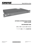
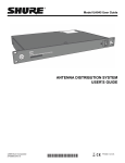
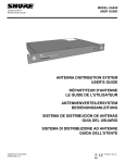
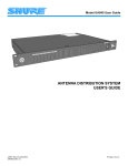
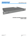
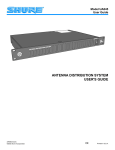
MODEL UA845 USER GUIDE ANTENNA DISTRIBUTION SYSTEM USER'S GUIDE RÉPARTITEUR D'ANTENNE LE GUIDE DE L'UTILISATEUR ANTENNENVERTEILERSYSTEM BEDIENUNGSANLEITUNG SISTEMA DE DISTRIBUCIÓN DE ANTENAS GUÍA DEL USUARIO SISTEMA DI DISTRIBUZIONE AD ANTENNE GUIDA DELL'UTENTE ©2009 Shure Incorporated 27F8635 (Rev. 11) Printed in U.S.A. POWERING ON/POWERING OFF THE UA845 Last powered on To avoid damaging internal components, the UA845 amplifier should be the last component in your system to be powered on. First powered off To avoid damaging internal components, the UA845 amplifier should be the first component in your system to be powered off. CONNECTING ANTENNA CABLES Accidentally connecting the center cable pin (power supply) to the cable housing (ground) may cause internal component damage. Use caution when installing cables. MISE SOUS TENSION/MISE HORS TENSION DU UA845 Pour éviter d'endommager les composants internes, l'amplificateur UA845 doit être le dernier composant du système à être mis sous tension. Pour éviter d'endommager les composants internes, l'amplificateur UA845 doit être le premier composant du système à être mis hors tension. RACCORDEMENT DES CÂBLES D'ANTENNE Le raccordement accidentel de la broche centrale du câble (alimentation) à la gaine du câble (masse) peut endommager les composants internes. Installer les câbles avec précaution. ENCENDIDO Y APAGADO DEL UA845 Para evitar dañar los componentes internos, el amplificador UA845 debe ser el último componente que se enciende en su sistema. Para evitar dañar los componentes internos, el amplificador UA845 debe ser el primer componente que se apaga en su sistema. CONEXION DE CABLES DE ANTENA La conexión accidental de la clavija central del cable (fuente de alimentación) a la caja del cable (tierra) puede causar daño a los componentes internos. Tenga cuidado al instalar los cables. AN-/AUSSCHALTEN DES UA845 Der Verstärker UA845 sollte als letzte Komponente Ihres System angeschaltet werden, um die Beschädigung interner Komponenten zu vermeiden. Der Verstärker UA845 sollte als erste Komponente Ihres System ausgeschaltet werden, um die Beschädigung interner Komponenten zu vermeiden. ANSCHLIESSEN DER ANTENNENKABEL Wenn der mittlere Kabelstift (Stromversorgung) versehentlich mit dem Kabelgehäuse (Masse) in Kontakt kommt, kann dies zur Beschädigung interner Komponenten führen. Beim Anschließen der Kabel vorsichtig vorgehen. ACCENSIONE/SPEGNIMENTO DEL MODELLO UA845 Per prevenire danni ai componenti interni, l'amplificatore UA845 va acceso per ultimo. Per prevenire danni ai componenti interni, l'amplificatore UA845 va spento per primo. COLLEGAMENTO DEI CAVI DELL'ANTENNA Il collegamento accidentale del piedino del cavo centrale (alimentazione) all'alloggiamento del cavo (massa) può provocare danni ai componenti interni. Fate attenzione durante l'installazione dei cavi. ! IMPORTANT SAFETY INSTRUCTIONS ! 1. 2. 3. 4. 5. 6. 7. 8. 9. 10. 11. READ these instructions. KEEP these instructions. HEED all warnings. FOLLOW all instructions. DO NOT use this apparatus near water. CLEAN ONLY with dry cloth. DO NOT block any ventilation openings. Install in accordance with the manufacturer's instructions. DO NOT install near any heat sources such as radiators, heat registers, stoves, or other apparatus (including amplifiers) that produce heat. DO NOT defeat the safety purpose of the polarized or grounding-type plug. A polarized plug has two blades with one wider than the other. A grounding type plug has two blades and a third grounding prong. The wider blade or the third prong are provided for your safety. If the provided plug does not fit into your outlet, consult an electrician for replacement of the obsolete outlet. PROTECT the power cord from being walked on or pinched, particularly at plugs, convenience receptacles, and the point where they exit from the apparatus. ONLY USE attachments/accessories specified by the manufacturer. 12. USE only with a cart, stand, tripod, bracket, or table specified by the manufacturer, or sold with the apparatus. When a cart is used, use caution when moving the cart/apparatus combination to avoid injury from tip-over. 13. UNPLUG this apparatus during lightning storms or when unused for long periods of time. REFER all servicing to qualified service personnel. Servicing is required when the apparatus has been damaged in any way, such as power-supply cord or plug is damaged, liquid has been spilled or objects have fallen into the apparatus, the apparatus has been exposed to rain or moisture, does not operate normally, or has been dropped. DO NOT expose the apparatus to dripping and splashing. DO NOT put objects filled with liquids, such as vases, on the apparatus. The MAINS plug or an appliance coupler shall remain readily operable. The airborne noise of the apparatus does not exceed 70dB (A). Apparatus with CLASS I construction shall be connected to a MAINS socket outlet with a protective earthing connection. To reduce the risk of fire or electric shock, do not expose this apparatus to rain or moisture. Do not attempt to modify this product. Doing so could result in personal injury and/or product failure. 14. 15. 16. 17. 18. 19. 20. This symbol indicates that dangerous voltage constituting a risk of electric shock is present within this unit. This symbol indicates that there are important operating and maintenance instructions in the literature accompanying this unit. WARNING: Voltages in this equipment are hazardous to life. No user-serviceable parts inside. Refer all servicing to qualified service personnel. The safety certifications do not apply when the operating voltage is changed from the factory setting. WARNING: This product contains a chemical known to the State of California to cause cancer and birth defects or other reproductive harm. MODEL UA845 ANTENNA DISTRIBUTION SYSTEM The Shure Model UA845 is an amplified, UHF Antenna Distribution System that expands a wireless microphone system by splitting one pair of antennas to multiple Shure UR4 or Shure ULX4 wireless receivers. It also amplifies RF signals to compensate for insertion loss due to splitting signal power to mulitple output connectors. Each UA845 allows up to four receivers to use the same antennas. CASCADE connectors allows connections to a fifth receiver or a second UA845. There are also power connectors for powering Shure UHF Wireless systems.Each system contains the following items: SYSTEM FEATURES • • • • • • • • • • UA845 Antenna Distribution System Rack-mounting hardware Surface-mounting hardware Front-mounting antenna hardware 18-in. Power OUTPUT Cord Power Cord Antenna cables for receiver connections The Shure Model UA845 ensures maximum sensitivity and signal processing capability, providing the widest radio range possible for the largest number of wireless receivers. To get the most from this system, follow these guidelines: • • • • • • When using long runs of cable for remote-mounted antennas, use the UA830 In-Line RF Amplifier and the Shure Model UA825 or UA850 Remote Antenna Extension cables (RG-8/X or equivalent), which have low loss at UHF operating frequencies Locate multiple transmitters more than 3 m [10 ft] from receiving antennas Expandability. The UA845 UHF Antenna Distribution System is designed for large UHF wireless systems. Each unit allows up to four wireless receivers to use the same two antennas, and the CASCADE ports allow connection to a fifth receiver or a second UA845. Compatibility. The UA845 is compatible with all Shure wireless microphone receivers operating within a compatible frequency range (see UHF Carrier Frequency Ranges in the Specifications section). CASCADE Ports. Two 50 , BNC-type antenna CASCADE ports allow an additonal UA845 unit or a fifth wireless receiver. A large wireless system can be run off of a single pair of antennas. Power OUTPUT and OUT Connectors. Up to five (5) UR4 receivers can be daisy-chained and powered from a single source via the Power OUTPUT connectors. Low Noise and Intermodulation Distortion. The UA845 maintains clean signals with minimal distortion. Insertion Loss Compensation. Whenever a signal is split to multiple output ports, there is a loss in signal strength. The UA845 amplifies signals to compensate, ensuring a strong signal to the receivers. Front-Mounted Antennas. The UA845 comes with hardware to front-mount the antennas, if desired. CONTROLS AND CONNECTORS FRONT PANEL UA845 UHF ANTENNA DISTRIBUTION SYSTEM 1 2 POWER ON/OFF SWITCH POWER INDICATOR BACK PANEL 1 1 2 2 3 4 5 3 AC Power INPUT Connector. 3 AC Power OUTPUT Connector. Each UA845 has a Power OUTPUT connector for daisy-chaining up to five (5) Shure Model UR4 UHF Diversity Single or Dual Receivers to a single power source. 4 NOTE: This connector does not work for Shure ULX4 Receivers. 5 ENGLISH 7 4 5 ANTENNA IN Ports, Channel A & B. BNC-type connectors for antennas. RF CASCADE Connectors (Output connector 5), Channel A & B. BNC-type connectors for adding a fifth receiver, or additional UA845's, permitting more wireless receivers to be connected. RF OUTPUT Connectors, Channel A & B. BNC-type connectors for up to four wireless receivers. SYSTEM INSTALLATION INSTALLING FRONT-MOUNTED ANTENNAS INSTALLING REMOTE ANTENNAS Remote-mounted antennas have the advantage of being free from the unit and closer to the transmitters. They can be placed anywhere within the recommended cable length, creating a much wider radio reception range and further reducing the possibility of signal dropout. When remote-mounted antennas are desirable, please ask your Shure dealer for information on the UA830 In-Line RF Amplifier. Cables are available in UA825 (7.5 m [25 ft]) and UA850 (15 m [50 ft]) versions. UA845 power UA845 UHF Antenna Distribution System power UA845 UHF Antenna Distribution System power UA845 UHF Antenna Distribution System RECEIVERS The UA845 comes equipped for front-mounted antennas. Front-mounting improves RF performance of the system by moving the antennas to the front of the rack. When a unit is located in a rack, antennas should be either frontor remote-mounted. 1. Insert the bulkhead adapters through the holes in each bracket, and secure them from each side, using the supplied hardware. 2. Connect the supplied antenna cables to the receiver antenna inputs and adapters. 3. Install the antennas onto the bulkhead adapters protruding through the front panel. NOTE: For the best results, point the antennas up and away from each other at 45angles from vertical. This ensures the best possible reception and greatly reduces the possibility of signal dropout. Always perform a walk-through test of the system in the performing area before using a wireless system. CONNECTING RECEIVERS SINGLE UA845 SETUP MULTIPLE UA845 SETUP 1. Using low-loss, 50 coaxial cables (RG-58 or equivalent), connect the right and left (Channels 1 through 4, A and B) RF OUTPUT ports on the UA845 to the corresponding left and right antenna inputs on each receiver. Use the CASCADE ports to connect a fifth receiver. 2. Using the supplied power cable, connect the UA845 to a power outlet. 3. To daisy-chain UR4 Receivers together with Power OUTPUT cables, connect the Power OUTPUT connector of the UA845 to the Power INPUT connector of one receiver. Connect the remaining receivers similarly. Connect the POWER INPUT of the unit to a power supply. 1. Connect the CASCADE ports (connector 5) for RF OUTPUT Channels A and B of one UA845 to the ANTENNA INPUT, channels A and B, of a UR4 receiver, or a second UA845. 2. If desired, connect additional units in the same manner. 3. To daisy-chain UR4 Receivers together with Power OUTPUT cables, connect the Power OUTPUT connector of the UA845 to the Power INPUT connector of one receiver. Connect the remaining receivers similarly. Connect the POWER INPUT of the unit to an AC power supply. WARNING: When adding additional UA845's to a system, each UA845 should be connected to a separate power supply. No more NOTE: No more than five (5) Shure UHF receivers should be powered through a daisy-chain from a single UA845. than five (5) receivers can be powered from a single UA845. Daisy-chaining multiple UA845's through the Power OUTPUT ports will overload a single power supply, possibly causing damage to the equipment. 8 ENGLISH SINGLE UA845 SETUP MULTIPLE UA845 SETUP ENGLISH 9 SPECIFICATIONS UHF Carrier Frequency Range UA845-SWB ............................................................... 470-952 MHz Certification UA845: LISTED by UL and CUL (U.S. and Canada), IC and FCC; IC Certified (Canada). Meets applicable European directives for CE marking eligibility. Meets Requirements of EMC Standard and 301 489 Parts 1 and 9. Meets the essential requirements of the European R&TTE Directive 99/5/EC and are eligible to carry the CE marking. Distributed Output Level (Gain) 3.5 dB typical, 2.0 dB to 5.0 dB from antenna input (Output ports 1–4). 0.5 dB typical, –1.0 dB to 2.0 dB from antenna input (Cascade port) Models: UA845 US, UK, E: 3 dB typical, 0 dB to 3.5 dB from antenna input (Output ports 1–4) 1 dB typical, –1.6 dB to +1.8 dB from antenna input (Cascade port) FURNISHED ACCESSORIES 2 ft. Coaxial Antenna Cable (RG-58) (12) .................................UA802 Output Connector Isolation .......................................................................... Greater than 25 dB OPTIONAL ACCESSORIES Third Order Intercept Point (3 OIP) ............................................................................... Typical 24 dBm Input/Output Antenna Connector Type ........................................................................................ BNC-type 1/2-Wave Antenna UA820A .....................................................................774–865 MHz UA820B.....................................................................690–746 MHz UA820D.....................................................................554–590 MHz UA820G..................................................................... 470-530 MHz UA820X ..................................................................... 944-952 MHz 25 ft. Coaxial Cable (RG-8/X)...................................................UA825 50 ft. Coaxial Cable (RG-8/X)...................................................UA850 30.4 m (100 ft.) Antenna Extension Cable.............................UA8100 In-Line RF Amplifier UA830A .....................................................................782–810 MHz UA830C .....................................................................800–830 MHz UA830KK...................................................................838–862 MHz UA830WB ..................................................................470–900 MHz UA830USTV ............................................................... 470-698 MHz UA830X ..................................................................... 944-952 MHz Active Directional Antenna UA870A ....................................................................782–810 MHz UA870MB ..................................................................800–830 MHz UA870KK...................................................................838–862 MHz UA870WB ..................................................................470–900 MHz UA870USTV ............................................................... 470-698 MHz UA870X ..................................................................... 944-952 MHz AC Power Consumption .......................................................................15 W per unit typical. REPLACEMENT PARTS Input/Output AC Line Voltage ............................................. 100 to 240 Vac, 50/60 Hz, unswitched DC Output Voltage ....................................................................... 12 Vdc, 4 connectors Maximun Current Supply from DC Outputs ........................................................................................ 1.1 Amps Impedance ...............................................................................................50 Operating Temperature Range .....................................................–7 C (+20 F) to 49C (+120 F) Overall Dimensions 44.5 mm high x 482.6 mm wide x 295.3 mm deep (1 3/4 x 19 5/8 x 11inches) Net Weight ........................................................................3.32 Kg (7 lbs, 5 oz) Hardware Kit....................................................................90XN1371 Bulkhead Adapters ............................................................. 95A8994 120 VAC Power Line Cord ...................................................95B8389 230 VAC Power Line Cord ................................................... 95C8247 240 VAC Power Line Cord (U.K.).......................................... 95A8713 120 VAC, 16-in. Power-Through Cord ...................................95B8576 230 VAC, 18-in. Power-Through Cord ...................................95B8678 THIS RADIO EQUIPMENT IS INTENDED FOR USE IN MUSICAL PROFESSIONAL ENTERTAINMENT AND SIMILAR APPLICATIONS. NOTE: THIS RADIO APPARATUS MAY BE CAPABLE OF OPERATING ON SOME FREQUENCIES NOT AUTHORIZED IN YOUR REGION. PLEASE CONTACT YOUR NATIONAL AUTHORITY TO OBTAIN INFORMATION ON AUTHORIZED FREQUENCIES FOR WIRELESS MICROPHONE PRODUCTS IN YOUR REGION LICENSING AND WARRANTY INFORMATION Warranty. Shure Incorporated (“Shure”) hereby warrants that these products will be free from defects in material and workmanship for a period of two years from the date of purchase. At its option, Shure will repair or replace the defective product and promptly return it to you, or refund the purchase price. Retain proof of purchase to validate the purchase date and return it with any warranty claim. If you believe this product is defective within the warranty period, carefully repack the unit, insure it, and return it postpaid to: Shure Incorporated Attention: Service Department 5800 W. Touhy Avenue Niles, IL 60714-4608 U.S.A. For service outside the United States, return the product to your authorized Shure Distribution Center. All claims of defects or shortage should be directed to the above address. Please furnish model number, operating frequency, and date, place and proof of purchase (such as a copy of your sales receipt) to establish warranty. Your letter should include all pertinent details including applicable model or part numbers and a brief description of the problem. Do not mail any units or parts to Shure unless requested to do so by Shure's Service Department. Any returned items must have prior authorization. Unauthorized returns are delayed in handling; these delays can be avoided by contacting Shure in advance and furnishing the necessary information. Shure reserves the right to make design changes and product improvements on any previously manufactured products. Shure also reserves the right to ship new and/or improved products which are similar to the form, fit and function of the originally ordered products. Licensing. Changes or modifications not expressly approved by Shure Incorporated could void your authority to operate the equipment. Licensing of Shure wireless microphone equipment is the user's responsibility, and licensability depends on the user's classification and application, and on the selected frequency. Shure strongly urges the user to contact the appropriate telecommunications authority concerning proper licensing, and before choosing and ordering frequencies other than standard frequencies. 10 ENGLISH EU DECLARATION OF CONFORMITY We, of Shure Incorporated 5800 Touhy Avenue Niles, Illinois, 60714-4608 U.S.A. Phone: (847) 600-2000 Web: www.Shure.com Declare under our sole responsibility that the following product Model: UA845SWB Description: Antenna Distribution Amplifier conforms to the essential requirements of European Low Voltage Directive 2006/95/EC European EMC Directive 2004/108/EC The product complies with the following product family, harmonized or national standards: EN 301 489-9 V1.4.1 (2007-11) EN61000-3-2:2006 EN 61000-3-3 Amendment: 1995, A1:2001, A2 2005 EN60065:2002 The technical documentation is kept at: Shure Incorporated, Corporate Quality Engineering Division SHURE Europe GmbH, EMEA Approval Manufacturer: Shure Incorporated Signed: __________________________________ Date: 13 July 2009 Name and Title: Craig Kozokar, EMC Project Engineer, Corporate Quality Engineering Division European Representative: SHURE Europe GmbH Signed: __________________________________ Date: 13 July 2009 Name and Title: Wolfgang Bilz, Dipl. Ing. (FH), EMEA Approval SHURE Europe GmbH Headquarters Europe, Middle East & Africa Wannenäcker Str. 28 D-74078 Heilbronn, Germany Phone: +49 - (0)7131 - 7214 - 0 Fax: +49 - (0)7131 - 7214 - 14 www.shure.com United States: Shure Incorporated 5800 West Touhy Avenue Niles, IL 60714-4608 USA Europe, Middle East, Africa: Shure Europe GmbH Wannenäckestr. 28, 74078 Heilbronn, Germany Phone: 847-600-2000 Fax: 847-600-1212 Email: [email protected] Phone: 49-7131-72140 Fax: 49-7131-721414 Email: [email protected] ©2009 Shure Incorporated Asia, Pacific: Shure Asia Limited Unit 301, 3rd Floor Citicorp Centre 18, Whitfield Road Causeway Bay, Hong Kong Phone: 852-2893-4290 Fax: 852-2893-4055 Email: [email protected] Canada, Latin America, Caribbean: Shure Incorporated 5800 West Touhy Avenue Niles, IL 60714-4608 USA Phone: 847-600-2000 Fax: 847-600-6446 Email: [email protected]