1
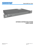
Model UA845
User Guide
UHF
POW ER
A NTEN
NA
UTION
DISTRIB
SYSTE
M
ANTENNA DISTRIBUTION SYSTEM
USER'S GUIDE
27E8635 (CE)
©2003 Shure Incorporated
Printed in U.S.A.
TABLE OF CONTENTS
SAFETY INFORMATION . . . . . . . . . . . . . . . . . . . . . . . . . . . . . . . . . . . . . . . . . . . . . . . . . . . . . . . . . . . . . . . . . . . . . 4
ENGLISH . . . . . . . . . . . . . . . . . . . . . . . . . . . . . . . . . . . . . . . . . . . . . . . . . . . . . . . . . . . . . . . . . . . . . . . . . . . . . . . . . 6
CONTROLS AND CONNECTORS . . . . . . . . . . . . . . . . . . . . . . . . . . . . . . . . . . . . . . . . . . . . . . . . . . . . . . . . . . 7
SYSTEM INSTALLATION . . . . . . . . . . . . . . . . . . . . . . . . . . . . . . . . . . . . . . . . . . . . . . . . . . . . . . . . . . . . . . . . . 8
CONNECTING RECEIVERS . . . . . . . . . . . . . . . . . . . . . . . . . . . . . . . . . . . . . . . . . . . . . . . . . . . . . . . . . . . . . . . 9
SPECIFICATIONS . . . . . . . . . . . . . . . . . . . . . . . . . . . . . . . . . . . . . . . . . . . . . . . . . . . . . . . . . . . . . . . . . . . . . . 11
LICENSING AND WARRANTY INFORMATION . . . . . . . . . . . . . . . . . . . . . . . . . . . . . . . . . . . . . . . . . . . . . . . 12
FRANÇAIS . . . . . . . . . . . . . . . . . . . . . . . . . . . . . . . . . . . . . . . . . . . . . . . . . . . . . . . . . . . . . . . . . . . . . . . . . . . . . . .
COMMANDES ET CONNECTEURS . . . . . . . . . . . . . . . . . . . . . . . . . . . . . . . . . . . . . . . . . . . . . . . . . . . . . . . .
INSTALLATION DU SYSTÈME . . . . . . . . . . . . . . . . . . . . . . . . . . . . . . . . . . . . . . . . . . . . . . . . . . . . . . . . . . . .
BRANCHEMENT DES RÉCEPTEURS . . . . . . . . . . . . . . . . . . . . . . . . . . . . . . . . . . . . . . . . . . . . . . . . . . . . .
FICHE TECHNIQUE . . . . . . . . . . . . . . . . . . . . . . . . . . . . . . . . . . . . . . . . . . . . . . . . . . . . . . . . . . . . . . . . . . . .
INFORMATIONS DE LICENCE ET DE GARANTIE . . . . . . . . . . . . . . . . . . . . . . . . . . . . . . . . . . . . . . . . . . . .
13
14
15
16
18
19
DEUTSCH . . . . . . . . . . . . . . . . . . . . . . . . . . . . . . . . . . . . . . . . . . . . . . . . . . . . . . . . . . . . . . . . . . . . . . . . . . . . . . .
BEDIENELEMENTE UND STECKVERBINDER . . . . . . . . . . . . . . . . . . . . . . . . . . . . . . . . . . . . . . . . . . . . . . .
SYSTEMINSTALLATION. . . . . . . . . . . . . . . . . . . . . . . . . . . . . . . . . . . . . . . . . . . . . . . . . . . . . . . . . . . . . . . . .
ANSCHLUSS DER EMPFÄNGER . . . . . . . . . . . . . . . . . . . . . . . . . . . . . . . . . . . . . . . . . . . . . . . . . . . . . . . . .
TECHNISCHE DATEN . . . . . . . . . . . . . . . . . . . . . . . . . . . . . . . . . . . . . . . . . . . . . . . . . . . . . . . . . . . . . . . . . .
LIZENZ- UND GARANTIEINFORMATIONEN . . . . . . . . . . . . . . . . . . . . . . . . . . . . . . . . . . . . . . . . . . . . . . . . .
20
21
22
23
25
26
ESPAÑOL . . . . . . . . . . . . . . . . . . . . . . . . . . . . . . . . . . . . . . . . . . . . . . . . . . . . . . . . . . . . . . . . . . . . . . . . . . . . . . .
CONTROLES Y CONECTORES . . . . . . . . . . . . . . . . . . . . . . . . . . . . . . . . . . . . . . . . . . . . . . . . . . . . . . . . . . .
INSTALACION DEL SISTEMA . . . . . . . . . . . . . . . . . . . . . . . . . . . . . . . . . . . . . . . . . . . . . . . . . . . . . . . . . . . .
CONEXION DE RECEPTORES . . . . . . . . . . . . . . . . . . . . . . . . . . . . . . . . . . . . . . . . . . . . . . . . . . . . . . . . . . .
ESPECIFICACIONES . . . . . . . . . . . . . . . . . . . . . . . . . . . . . . . . . . . . . . . . . . . . . . . . . . . . . . . . . . . . . . . . . . .
INFORMACION RESPECTO A LICENCIA DE USO Y GARANTIA . . . . . . . . . . . . . . . . . . . . . . . . . . . . . . . .
27
28
29
30
32
33
ITALIANO. . . . . . . . . . . . . . . . . . . . . . . . . . . . . . . . . . . . . . . . . . . . . . . . . . . . . . . . . . . . . . . . . . . . . . . . . . . . . . . .
COMANDI E CONNETTORI . . . . . . . . . . . . . . . . . . . . . . . . . . . . . . . . . . . . . . . . . . . . . . . . . . . . . . . . . . . . . .
INSTALLAZIONE DEL SISTEMA . . . . . . . . . . . . . . . . . . . . . . . . . . . . . . . . . . . . . . . . . . . . . . . . . . . . . . . . . .
COLLEGAMENTO DEI RICEVITORI. . . . . . . . . . . . . . . . . . . . . . . . . . . . . . . . . . . . . . . . . . . . . . . . . . . . . . . .
SCHEDA TECNICA . . . . . . . . . . . . . . . . . . . . . . . . . . . . . . . . . . . . . . . . . . . . . . . . . . . . . . . . . . . . . . . . . . . . .
INFORMAZIONI SUL RILASCIO DI LICENZA E GARANZIA . . . . . . . . . . . . . . . . . . . . . . . . . . . . . . . . . . . . .
34
35
36
37
39
40
3
SAFETY INFORMATION
safety information
! IMPORTANT SAFETY INSTRUCTIONS !
1.
2.
3.
4.
5.
6.
7.
8.
9.
10.
READ these instructions.
KEEP these instructions.
HEED all warnings.
FOLLOW all instructions.
DO NOT use this apparatus near water.
CLEAN ONLY with dry cloth.
DO NOT block any ventilation openings. Install in accordance with the manufacturer's instructions.
DO NOT install near any heat sources such as radiators, heat registers, stoves,
or other apparatus (including amplifiers) that produce heat.
DO NOT defeat the safety purpose of the polarized or grounding-type plug.
A polarized plug has two blades with one wider than the other. A grounding
type plug has two blades and a third grounding prong. The wider blade or
the third prong are provided for your safety. If the provided plug does not fit
into your outlet, consult an electrician for replacement of the obsolete outlet.
PROTECT the power cord from being walked on or pinched, particularly at plugs,
convenience receptacles, and the point where they exit from the apparatus.
11.
12.
13.
14.
15.
This symbol indicates that there are important operating and
maintenance instructions in the literature accompanying this unit.
ONLY USE attachments/accessories specified by the manufacturer.
USE only with a cart, stand, tripod, bracket, or table
specified by the manufacturer, or sold with the
apparatus. When a cart is used, use caution when
moving the cart/apparatus combination to avoid
injury from tip-over.
UNPLUG this apparatus during lightning storms or when unused for long periods of
time.
REFER all servicing to qualified service personnel. Servicing is required when the
apparatus has been damaged in any way, such as power-supply cord or plug is damaged, liquid has been spilled or objects have fallen into the apparatus, the apparatus
has been exposed to rain or moisture, does not operate normally, or has been
dropped.
DO NOT expose the apparatus to dripping and splashing. DO NOT put objects
filled with liquids, such as vases, on the apparatus.
This symbol indicates that dangerous voltage constituting a risk
of electric shock is present within this unit.
! CONSIGNES DE SÉCURITÉ IMPORTANTES !
1.
2.
3.
4.
5.
6.
7.
8.
9.
LIRE ces consignes.
CONSERVER ces consignes.
OBSERVER tous les avertissements.
SUIVRE toutes les consignes.
NE PAS utiliser cet appareil à proximité de l'eau.
NETTOYER UNIQUEMENT avec un chiffon sec.
NE PAS obstruer les ouvertures de ventilation. Installer en respectant les consignes du fabricant.
Ne pas installer à proximité d'une source de chaleur telle qu'un radiateur, une
bouche de chaleur, un poêle ou d'autres appareils (dont les amplificateurs) produisant de la chaleur.
NE PAS détériorer la sécurité de la fiche polarisée ou de la fiche de terre. Une
fiche polarisée comporte deux lames dont l'une est plus large que l'autre. Une
fiche de terre comporte deux lames et une troisième broche de mise à la terre.
La lame la plus large ou la troisième broche assure la sécurité de l'utilisateur. Si
la fiche fournie ne s'adapte pas à la prise électrique, demander à un électricien
de remplacer la prise hors normes.
10.
11.
12.
13.
14.
15.
Ce symbole indique que la documentation fournie avec
l'appareil contient des instructions d'utilisation et d'entretien
importantes.
PROTÉGER le cordon d'alimentation afin que personne ne marche dessus et que
rien ne le pince, en particulier au niveau des fiches, des prises de courant et du point
de sortie de l'appareil.
UTILISER UNIQUEMENT les accessoires spécifiés par le fabricant.
UTILISER uniquement avec un chariot, un pied, un trépied,
un support ou une table spécifié par le fabricant ou vendu
avec l'appareil. Si un chariot est utilisé, déplacer l'ensemble
chariot-appareil avec précaution afin de ne pas le renverser,
ce qui pourrait entraîner des blessures.
DÉBRANCHER l'appareil pendant les orages ou quand il ne sera pas utilisé pendant
longtemps.
CONFIER toute réparation à du personnel qualifié. Des réparations sont nécessaires
si l'appareil est endommagé de quelque façon que ce soit, comme par exemple : cordon ou prise d'alimentation endommagé, liquide renversé ou objet tombé à l'intérieur
de l'appareil, exposition de l'appareil à la pluie ou à l'humidité, appareil qui ne marche
pas normalement ou que l'on a fait tomber.
NE PAS exposer cet appareil aux égouttures et aux éclaboussements. NE PAS poser
des objets contenant de l'eau, comme des vases, sur l'appareil.
Ce symbole indique la présence d'une tension dangereuse
dans l'appareil constituant un risque de choc électrique.
4
! WICHTIGE SICHERHEITSHINWEISE !
1.
2.
3.
4.
5.
6.
7.
8.
9.
10.
Diese Hinweise LESEN.
Diese Hinweise AUFHEBEN.
Alle Warnhinweise BEACHTEN.
Alle Anweisungen BEFOLGEN.
Dieses Gerät NICHT in der Nähe von Wasser verwenden.
NUR mit einem sauberen Tuch REINIGEN.
KEINE Lüftungsöffnungen verdecken. Gemäß den Anweisungen des Herstellers einbauen.
Nicht in der Nähe von Wärmequellen, wie Heizkörpern, Raumheizungen,
Herden oder anderen Geräten (einschließlich Verstärkern) installieren, die
Wärme erzeugen.
Die Schutzfunktion des Schukosteckers NICHT umgehen. Bei Steckern für die
USA gibt es polarisierte Stecker, bei denen ein Leiter breiter als der andere ist;
US-Stecker mit Erdung verfügen über einen dritten Schutzleiter. Bei diesen
Steckerausführungen dient der breitere Leiter bzw. der Schutzleiter Ihrer
Sicherheit. Wenn der mitgelieferte Stecker nicht in die Steckdose passt, einen
Elektriker mit dem Austauschen der veralteten Steckdose beauftragen.
VERHINDERN, dass das Netzkabel gequetscht oder darauf getreten wird, insbesondere im Bereich der Stecker, Netzsteckdosen und an der Austrittsstelle
vom Gerät.
11.
12.
13.
14.
15.
Dieses Symbol zeigt an, dass gefährliche Spannungswerte,
die ein Stromschlagrisiko darstellen, innerhalb dieses Geräts
auftreten.
NUR das vom Hersteller angegebene Zubehör und entsprechende Zusatzgeräte verwenden.
NUR in Verbindung mit einem vom Hersteller angegebenen
oder mit dem Gerät verkauften Transportwagen, Stand, Stativ,
Träger oder Tisch verwenden. Wenn ein Transportwagen verwendet wird, beim Verschieben der Transportwagen-GeräteEinheit vorsichtig vorgehen, um Verletzungen durch Umkippen
Das Netzkabel dieses Geräts während Gewittern oder bei längeren Stillstandszeiten
aus der Steckdose ABZIEHEN.
Alle Reparatur- und Wartungsarbeiten von qualifiziertem Kundendienstpersonal
DURCHFÜHREN LASSEN. Kundendienst ist erforderlich, wenn das Gerät auf
irgendwelche Weise beschädigt wurde, z.B. wenn das Netzkabel oder der
Netzstecker beschädigt wurden, wenn Flüssigkeiten in das Gerät verschüttet wurden
oder Fremdkörper hineinfielen, wenn das Gerät Regen oder Feuchtigkeit ausgesetzt
war, nicht normal funktioniert oder fallen gelassen wurde.
Dieses Gerät vor Tropf- und Spritzwasser SCHÜTZEN. KEINE mit Wasser gefüllten
Gegenstände wie zum Beispiel Vasen auf das Gerät STELLEN.
Dieses Symbol zeigt an, dass das diesem Gerät beiliegende
Handbuch wichtige Betriebs- und Wartungsanweisungen enthält.
! INSTRUCCIONES IMPORTANTES DE SEGURIDAD !
1.
2.
3.
4.
5.
6.
7.
8.
9.
LEA estas instrucciones.
CONSERVE estas instrucciones.
PRESTE ATENCION a todas las advertencias.
SIGA todas las instrucciones.
NO utilice este aparato cerca del agua.
LIMPIESE UNICAMENTE con un trapo seco.
NO obstruya ninguna de las aberturas de ventilación. Instálese según lo
indicado en las instrucciones del fabricante.
No instale el aparato cerca de fuentes de calor tales como radiadores, registros
de calefacción, estufas u otros aparatos (incluyendo amplificadores) que
produzcan calor.
NO anule la función de seguridad del enchufe polarizado o con clavija de
puesta a tierra. Un enchufe polarizado tiene dos patas, una más ancha que la
otra. Un enchufe con puesta a tierra tiene dos patas y una tercera clavija con
puesta a tierra. La pata más ancha o la tercera clavija se proporciona para su
seguridad. Si el tomacorriente no es del tipo apropiado para el enchufe, consulte a un electricista para que sustituya el tomacorriente de estilo anticuado.
10.
11.
12.
13.
14.
15.
Este símbolo indica que la unidad contiene niveles de voltaje
peligrosos que representan un riesgo de choques eléctricos.
PROTEJA el cable eléctrico para evitar que personas lo pisen o estrujen, particularmente en sus enchufes, en los tomacorrientes y en el punto en el cual sale del
aparato.
UTILICE únicamente los accesorios especificados por el fabricante.
UTILICESE únicamente con un carro, pedestal, trípode,
escuadra o mesa del tipo especificado por el fabricante o vendido con el aparato. Si se usa un carro, el mismo debe moverse con sumo cuidado para evitar que se vuelque con el
aparato.
DESENCHUFE el aparato durante las tormentas eléctricas, o si no va a ser utilizado
por un lapso prolongado.
TODA reparación debe ser llevada a cabo por técnicos calificados. El aparato
requiere reparación si ha sufrido cualquier tipo de daño, incluyendo los daños al
cordón o enchufe eléctrico, si se derrama líquido sobre el aparato o si caen objetos
en su interior, si ha sido expuesto a la lluvia o la humedad, si no funciona de modo
normal, o si se ha caído.
NO exponga este aparato a chorros o salpicaduras de líquidos. NO coloque objetos
llenos con líquido, tales como floreros, sobre el aparato.
Este símbolo indica que la literatura que acompaña a esta
unidad contiene instrucciones importantes de funcionamiento
y mantenimiento.
! ISTRUZIONI IMPORTANTI PER LA SICUREZZA !
1.
2.
3.
4.
5.
6.
7.
8.
9.
EGGETE queste istruzioni.
CONSERVATE queste istruzioni.
OSSERVATE tutte le avvertenze.
SEGUITE tutte le istruzioni.
NON usate questo apparecchio vicino all'acqua.
PULITE l'apparecchio SOLO con un panno asciutto.
NON ostruite alcuna apertura per l'aria di raffreddamento. Installate l'apparecchio seguendo le istruzioni del costruttore.
NON installate l'apparecchio accanto a fonti di calore quali radiatori, aperture
per l'efflusso di aria calda, forni o altri apparecchi (amplificatori inclusi) che generino calore.
NON modificate la spina polarizzata o con spinotto di protezione. Una spina polarizzata è dotata di due lame, una più ampia dell'altra. Una spina con spinotto è dotata di due lame e di un terzo polo di messa a terra. La lama più ampia ed il terzo
polo hanno lo scopo di tutelare la vostra incolumità. Se la spina in dotazione non si
adatta alla presa di corrente, rivolgetevi ad un elettricista per far eseguire le modifiche necessarie.
10.
11.
12.
13.
14.
15.
Questo simbolo indica la presenza di alta tensione all'interno
dell'apparecchio, che comporta il rischio di folgorazione.
EVITATE di calpestare il cavo di alimentazione o di comprimerlo, specie in corrispondenza di spine, prese di corrente e punto di uscita dall'apparecchio.
USATE ESCLUSIVAMENTE i dispositivi di collegamento e gli accessori specificati
dal costruttore.
USATE l'apparecchio solo con carrelli, sostegni, treppiedi,
staffe o tavoli specificati dal costruttore o venduti insieme
all'apparecchio stesso. Se usate un carrello, fate attenzione
durante gli spostamenti per evitare infortuni causati da un
eventuale ribaltamento del carrello stesso.
SCOLLEGATE l'apparecchio dalla presa di corrente in caso di temporali o di non utilizzo per un lungo periodo.
RIVOLGETEVI a personale di assistenza qualificato per qualsiasi intervento. È necessario intervenire sull'apparecchio ogniqualvolta sia stato danneggiato, in qualsiasi
modo, ad esempio in caso di danneggiamento di spina o cavo di alimentazione, versamento di liquido sull'apparecchio o caduta di oggetti su di esso, esposizione
dell'apparecchio a pioggia o umidità, funzionamento irregolare o caduta.
NON esponetelo a sgocciolamenti o spruzzi. NON appoggiate sull'apparecchio
oggetti pieni di liquidi, ad esempio vasi da fiori.
Questo simbolo indica la presenza di istruzioni importanti per
l'uso e la manutenzione nella documentazione in dotazione
all'apparecchio.
5
ENGLISH
MODEL UA845 ANTENNA DISTRIBUTION SYSTEM
English
✓ Power Cord
✓ Antenna cables for receiver connections
✓ DC power cables for receiver connections to DC power con-
The Shure Model UA845 is an amplified, UHF Antenna Distribution
System designed to expand a wireless microphone system by splitting
one pair of antennas to multiple Shure U4 or Shure UC4 wireless receivers. It also amplifies RF signals to compensate for insertion loss
due to splitting signal power to mulitple output connectors. Each
UA845 allows up to four receivers to use the same antennas. CASCADE connectors allows connections to a fifth receiver or a second
UA845. There are also power connectors for powering Shure UHF
and UC Wireless systems.
Each system contains the following items:
nectors on UC receivers.
The Shure Model UA845 has been developed to ensure maximum
sensitivity and signal processing capability, providing the widest radio
range possible for the largest number of wireless receivers. To get the
most from this system, follow these guidelines:
•
When using long runs of cable for remote-mounted antennas, use the UA830 In-Line RF Amplifier and the Shure Model UA825 or UA850 Remote Antenna Extension cables
(RG-8/X or equivalent), which have low loss at UHF operating frequencies
•
Locate multiple transmitters more than 3 m [10 ft] from receiving antennas
✓ UA845 Antenna Distribution System
✓ Rack-mounting hardware
✓ Surface-mounting hardware
✓ Front-mounting antenna hardware
✓ 18-in. Power OUTPUT Cord
SYSTEM FEATURES
•
•
•
•
Expandability. The UA845 UHF Antenna Distribution System is designed for large UHF wireless systems. Each unit
allows up to four wireless receivers to use the same two antennas, and the CASCADE ports allow connection to a fifth
receiver or a second UA845.
Compatibility. The UA845 is compatible with all Shure wireless microphone receivers operating within a compatible frequency range (see UHF Carrier Frequency Ranges in the
Specifications section).
CASCADE Ports. Two 50 W, BNC-type antenna CASCADE
ports allow an additonal UA845 unit or a fifth wireless receiver. A large wireless system can be run off of a single pair of
antennas.
•
•
•
6
Power OUTPUT and OUT Connectors. Up to five (5) U4 receivers can be daisy-chained and powered from a single
source via the Power OUTPUT connectors. Up to four (4)
UC4 receivers can be powered from the UA845 using the 12
Vdc OUT connectors.
Low Noise and Intermodulation Distortion. The UA845
maintains clean signals with minimal distortion.
Insertion Loss Compensation. Whenever a signal is split
to multiple output ports, there is a loss in signal strength. The
UA845 amplifies signals to compensate, ensuring a strong
signal to the receivers.
Front-Mounted Antennas. The UA845 comes with hardware to front-mount the antennas, if desired.
ENGLISH
CONTROLS AND CONNECTORS
FRONT PANEL (FIGURE 1)
1
FRONT PANEL
FIGURE 1
2
Power Indicator
Power ON/OFF Switch
BACK PANEL (FIGURE 2)
6
1
2
3
6
4
5
3
4
5
BACK PANEL
FIGURE 2
1
AC Power INPUT Connector.
RF CASCADE Connectors (Output connector 5), Channel A & B. BNC-type connectors for adding a fifth receiver,
or additional UA845's, permitting more wireless receivers to
be connected.
4
AC Power OUTPUT Connector. Each UA845 has a Power
OUTPUT connector for daisy-chaining up to five (5) Shure
Model U4 UHF Diversity Single or Dual Receivers to a single power source. NOTE: This connector does not work for
Shure UC4 Receivers.
2
3
ANTENNA IN Ports, Channel A & B. BNC-type connectors for antennas.
7
5
RF OUTPUT Connectors, Channel A & B. BNC-type connectors for up to four wireless receivers.
6
12 Vdc OUT Connectors. These power connectors are
designed to power up to four (4) Shure UC4 Wireless systems.
ENGLISH
SYSTEM INSTALLATION
Installing Front-Mounted Antennas
The UA845 comes equipped for front-mounted antennas.
Front-mounting improves RF performance of the system by moving
the antennas to the front of the rack. When a unit is located in a rack,
antennas should be either front- or remote-mounted.
1.
dropout. Always perform a walk-through test of the system in the
performing area before using a wireless system.
Mounting the UA845 in an Equipment Rack
NOTE: If the antennas are to be front-mounted, Shure recommends
connecting them before mounting the UA845 in the rack. Once the
UA845 is in the rack, it is more difficult to insert the bulkhead
adapters and connect the antenna cables.
Insert the bulkhead adapters through the holes in each bracket,
and secure them from each side, using the supplied hardware.
See Figure 3.
1.
2.
INSERTING BULKHEAD ADAPTERS
FIGURE 3
2.
Insert the unit into a 19-inch equipment rack.
Using the screws supplied, secure the unit to the rack (Figure 6).
RACK MOUNTING
FIGURE 6
Connect the supplied antenna cables to the receiver antenna
inputs and adapters. See Figure 4.
3.
If the antennas are remote mounted from the back of the rack,
insert the supplied plastic plugs into the holes on the front of the
brackets.
Installing Remote Antennas (Figure 7)
Remote-mounted antennas have the advantage of being free from
the unit and closer to the transmitters. They can be placed anywhere
within the recommended cable length, creating a much wider radio reception range and further reducing the possibility of signal dropout.
When remote-mounted antennas are desirable, please ask your Shure
dealer for information on the UA830 In-Line RF Amplifier. Cables are
available in UA825 (7.5 m [25 ft]) and UA850 (15 m [50 ft]) versions.
UA845
CONNECT ANTENNA CABLES
FIGURE 4
3.
Install the antennas onto the bulkhead adapters protruding
through the front panel. See Figure 5.
RECEIVERS
ATTACH ANTENNAS TO THE ADAPTERS
FIGURE 5
REMOTE-MOUNTED ANTENNAS
FIGURE 7
NOTE: For the best results, point the antennas up and away from
each other at 45° angles from vertical. This ensures the best
possible reception and greatly reduces the possibility of signal
8
ENGLISH
CONNECTING RECEIVERS
SINGLE UA845 SETUP (FIGURE 8)
1.
2.
3.
Using low-loss, 50 W coaxial cables (RG-58 or equivalent), connect the right and left (Channels 1 through 4, A and B) RF OUTPUT ports on the UA845 to the corresponding left and right
antenna inputs on each receiver. Use the CASCADE ports to
connect a fifth receiver.
Using the supplied power cable, connect the UA845 to a power
outlet.
To daisy-chain U4 Receivers together with Power OUTPUT
cables, connect the Power OUTPUT connector of the UA845 to
the Power INPUT connector of one receiver. Connect the remaining receivers similarly. Connect the POWER INPUT of the unit to
a power supply.
NOTE: No more than five (5) Shure UHF receivers should be
powered through a daisy-chain from a single UA845.
4.
UA845
12 VDC POWER CONNECTOR
ANT B IN
To power Shure UC4 receivers, connect the power input ports of
the UC4 receivers to the 12 Vdc OUT of the UA845. Up to four
UC4 Receivers can be powered.
CASCADE B
12 VDC POWER CONNECTOR
CASCADE A
ANT A IN
ANT B OUTS
AC PWR OUTPUT
ANT A OUTS
AC PWR INPUT
TO POWER SUPPLY
ANT B IN
AC PWR OUTPUT
U4 RECEIVER
ANT A IN
AC PWR INPUT
U4 RECEIVER
U4 RECEIVER
UC4 RECEIVER
UC4 RECEIVER
12 VDC PWR INPUT
ANT A IN
ANT B IN
SINGLE UA845 SETUP
FIGURE 8
9
ANT A IN
ANT B IN
ENGLISH
MULTIPLE UA845 SETUP (FIGURE 9)
1.
2.
3.
Connect the CASCADE ports (connector 5) for RF OUTPUT
Channels A and B of one UA845 to the ANTENNA INPUT, channels A and B, of a U4 receiver, a UC4 receiver, or a second
UA845.
If desired, connect additional units in the same manner.
To daisy-chain U4 Receivers together with Power OUTPUT
cables, connect the Power OUTPUT connector of the UA845 to
the Power INPUT connector of one receiver. Connect the remain-
ing receivers similarly. Connect the POWER INPUT of the unit to
an AC power supply.
WARNING: When adding additional UA845's to a system, each
UA845 should be connected to a separate power supply. No more
than five (5) receivers can be powered from a single UA845.
Daisy-chaining multiple UA845's through the Power OUTPUT ports
will overload a single power supply, possibly causing damage to the
equipment.
4.
To power Shure UC4 receivers, connect the power input ports of
the UC4 receivers to the 12 Vdc OUT of the UA845. Up to four
UC4 Receivers can be powered.
UA845
12 VDC POWER CONNECTOR
12 VDC POWER CONNECTOR
ANT A IN
ANT B IN
CASCADE B
AC PWR OUTPUT
CASCADE A
ANT A OUTS
ANT B OUTS
AC PWR INPUT
TO POWER SUPPLY
TO
RECEIVERS
TO
RECEIVERS
AC PWR OUTPUT
ANT B IN
AC PWR INPUT
U4 RECEIVER
ANT A IN
U4 RECEIVER
12 VDC PWR INPUT
ANT A IN
ANT B IN
UA845
UC4 RECEIVER
TO POWER SUPPLY
TO
RECEIVERS
TO RECEIVERS
U4 RECEIVER
TO UA845
ANT A IN
TO UA845 ANT B IN
MULTIPLE UA845 SETUP
FIGURE 9
10
Certification
UA845: Listed by UL and CUL (U.S. and Canada), IC and
FCC; IC Certified (Canada). Meets applicable European directives for CE marking eligibility. VDE GS-Certified. Meets
Requirements of EMC Standard and 301 489 Parts 1 and 9.
Meets the essential requirements of the European R&TTE
Directive 99/5/EC and are eligible to carry the CE marking.
UHF Carrier Frequency Range
UA845-UA ................................................... 782–806 MHz
UA845-UB ................................................... 692–716 MHz
UA845-MA .................................................. 782–810 MHz
UA845-MB .................................................. 800–830 MHz
UA845-KK ................................................... 838–862 MHz
UA845-MC .................................................. 774–782 MHz
UA845 US ................................................... 500–900 MHz
UA845 UK ................................................... 500–900 MHz
UA845 E...................................................... 500–900 MHz
Distributed Output Level (Gain)
Models UA845-UA, UB, MA, MB, KK, MC:
3.5 dB typical, 2.0 dB to 5.0 dB from antenna input
(Output ports 1–4).
0.5 dB typical, –1.0 dB to 2.0 dB from antenna input
(Cascade port)
ModelsUA845 US, UK and E:
3 dB typical, 0 dB to 3.5 dB from antenna input
(Output ports 1–4)
1 dB typical, –1.6 dB to +1.8 dB from antenna input
(Cascade port)
Output Connector Isolation
Greater than 25 dB
Third Order Intercept Point (3 OIP)
Typical 24 dBm
Input/Output AC Line Voltage
100 to 240 Vac, 50/60 Hz, unswitched
DC Output Voltage
12 Vdc, 4 connectors
Impedance
50 W
Operating Temperature Range
–7° C (+20° F) to 49° C (+120° F)
Overall Dimensions
44.5 mm high x 482.6 mm wide x 295.3 mm deep (1 3/4 x 19
x 11 5/8 inches)
Net Weight
3.32 Kg (7 lbs, 5 oz)
Input/Output Antenna Connector Type
BNC-type
AC Power Consumption
15 W per unit typical. When used with 4 UC4's, 55 W max.
Furnished Accessories
2 ft. Coaxial Antenna Cable (RG-58) (12) ................. UA802
Optional Accessories
1/ -Wave Antenna
2
UA820A........................................................(774–865 MHz)
UA820B........................................................(690–746 MHz)
UA820C .......................................................(662–698 MHz)
UA820D .......................................................(554–590 MHz)
UA820E........................................................(746–784 MHz)
25 ft. Coaxial Cable (RG-8/X) ................................... UA825
50 ft. Coaxial Cable (RG-8/X) ................................... UA850
30.4 m (100 ft.) Antenna Extension Cable ............. UA8100
In-Line RF Amplifier
UA830A........................................................(782–810 MHz)
UA830UB .....................................................(692–716 MHz)
UA830C .......................................................(800–830 MHz)
UA830D .......................................................(774–782 MHz)
UA830KK .....................................................(838–862 MHz)
UA830WB ....................................................(470–900 MHz)
Active Directional Antenna
UA870A .......................................................(782–810 MHz)
UA870MB.....................................................(800–830 MHz)
UA870MC ....................................................(774–782 MHz)
UA870KK .....................................................(838–862 MHz)
UA870UB .....................................................(692–716 MHz)
UA870WB ....................................................(470–900 MHz)
Replacement Parts
Hardware Kit ........................................................ 90VL1371
Bulkhead Adapters................................................. 95A8647
120 VAC Power Line Cord ..................................... 95A8389
230 VAC Power Line Cord ..................................... 95A8247
240 VAC Power Line Cord (U.K.)........................... 95A8713
120 VAC, 16-in. Power-Through Cord ................... 95A8576
230 VAC, 18-in. Power-Through Cord ................... 95A8678
12 Vdc Power Cables ............................................ 95A8420
THIS RADIO EQUIPMENT IS INTENDED FOR USE IN MUSICAL PROFESSIONAL ENTERTAINMENT AND SIMILAR APPLICATIONS.
NOTE: THIS RADIO APPARATUS MAY BE CAPABLE OF OPERATING ON SOME FREQUENCIES NOT AUTHORIZED IN YOUR REGION. PLEASE CONTACT YOUR NATIONAL AUTHORITY TO OBTAIN INFORMATION ON AUTHORIZED FREQUENCIES FOR WIRELESS MICROPHONE PRODUCTS IN YOUR REGION
11
ENGLISH
SPECIFICATIONS
ENGLISH
LICENSING AND WARRANTY INFORMATION
Warranty. Shure Incorporated (“Shure”) hereby warrants that
these products will be free from defects in material and workmanship
for a period of one year from the date of purchase. At its option, Shure
will repair or replace the defective product and promptly return it to you,
or refund the purchase price. Retain proof of purchase to validate the
purchase date and return it with any warranty claim. If you believe this
product is defective within the warranty period, carefully repack the
unit, insure it, and return it postpaid to:
cluding applicable model or part numbers and a brief description of the
problem. Do not mail any units or parts to Shure unless requested to
do so by Shure's Service Department. Any returned items must have
prior authorization. Unauthorized returns are delayed in handling;
these delays can be avoided by contacting Shure in advance and furnishing the necessary information.
Shure reserves the right to make design changes and product improvements on any previously manufactured products. Shure also reserves the right to ship new and/or improved products which are
similar to the form, fit and function of the originally ordered products.
Licensing. Changes or modifications not expressly approved by
Shure Incorporated could void your authority to operate the equipment. Licensing of Shure wireless microphone equipment is the user's
responsibility, and licensability depends on the user's classification
and application, and on the selected frequency. Shure strongly urges
the user to contact the appropriate telecommunications authority concerning proper licensing, and before choosing and ordering frequencies other than standard frequencies.
Shure Incorporated
Attention: Service Department
222 Hartrey Avenue
Evanston, IL 60202-3696 U.S.A.
For service outside the United States, return the product to your authorized Shure Distribution Center.
All claims of defects or shortage should be directed to the above address. Please furnish model number, operating frequency, and date,
place and proof of purchase (such as a copy of your sales receipt) to
establish warranty. Your letter should include all pertinent details in-
12
41
SHURE Incorporated Web Address: http://www.shure.com
5800 W. Touhy Avenue, Niles, IL 60714-4608, U.S.A.
Phone: 800-257-4873 Fax: 847-866-2279
In Europe, Phone: 49-7131-72140 Fax: 49-7131-721414
In Asia, Phone: 852-2893-4290 Fax: 852-2893-4055
Elsewhere, Phone: 847-866-2200 Fax: 847-866-2585