1
SAFETY PRECAUTIONS
(Read these precautions before using this product.)
Before using this product, please read this manual and the relevant manuals carefully and pay full
attention to safety to handle the product correctly.
In this manual, the safety precautions are classified into two levels: "
DANGER" and "
CAUTION".
DANGER
Indicates that incorrect handling may cause hazardous conditions,
resulting in death or severe injury.
CAUTION
Indicates that incorrect handling may cause hazardous conditions,
resulting in medium or slight personal injury or physical damage.
Under some circumstances, failure to observe the precautions given under "
CAUTION" may lead to
serious consequences.
Make sure that the end users read this manual and then keep the manual in a safe place for future
reference.
[Design Precautions]
DANGER
Configure safety circuits external to the programmable controller to ensure that the entire system
operates safely even when a fault occurs in the external power supply or the programmable
controller. Failure to do so may result in an accident due to an incorrect output or malfunction.
(1) Configure external safety circuits, such as an emergency stop circuit, protection circuit, and
protective interlock circuit for forward/reverse operation or upper/lower limit positioning.
(2) The programmable controller stops its operation upon detection of the following status, and the
output status of the system will be as shown below.
Status
Output
Overcurrent or overvoltage protection of the power supply module
is activated.
All outputs are turned off.
The CPU module detects an error such as a watchdog timer error
by the self-diagnostic function.
All outputs are held or turned off according to
the parameter setting.
All outputs may turn on when an error occurs in the part, such as I/O control part, where the CPU
module cannot detect any error. To ensure safety operation in such a case, provide a safety
mechanism or a fail-safe circuit external to the programmable controller. For a fail-safe circuit
example, refer to Chapter 10 LOADING AND INSTALLATION in the QCPU User's Manual
(Hardware Design, Maintenance and Inspection).
(3) Outputs may remain on or off due to a failure of an output module relay or transistor. Configure
an external circuit for monitoring output signals that could cause a serious accident.
A-1
[Design Precautions]
DANGER
In an output module, when a load current exceeding the rated current or an overcurrent caused by a
load short-circuit flows for a long time, it may cause smoke and fire. To prevent this, configure an
external safety circuit, such as a fuse.
Configure a circuit so that the programmable controller is turned on first and then the external power
supply.
If the external power supply is turned on first, an accident may occur due to an incorrect output or
malfunction.
For the operating status of each station after a communication failure, refer to relevant manuals for
the network.
Incorrect output or malfunction due to a communication failure may result in an accident.
When changing data of the running programmable controller from a peripheral connected to the
CPU module or from a personal computer connected to an intelligent function module, configure an
interlock circuit in the sequence program to ensure that the entire system will always operate safely.
For program modification and operating status change, read relevant manuals carefully and ensure
the safety before operation.
Especially, in the case of a control from an external device to a remote programmable controller,
immediate action cannot be taken for a problem on the programmable controller due to a
communication failure.
To prevent this, configure an interlock circuit in the sequence program, and determine corrective
actions to be taken between the external device and CPU module in case of a communication
failure.
CAUTION
Do not install the control lines or communication cables together with the main circuit lines or power
cables.
Keep a distance of 100mm (3.94 inches) or more between them.
Failure to do so may result in malfunction due to noise.
When a device such as a lamp, heater, or solenoid valve is controlled through an output module, a
large current (approximately ten times greater than normal) may flow when the output is turned from
off to on.
Take measures such as replacing the module with one having a sufficient current rating.
A-2
[Installation Precautions]
CAUTION
Use the programmable controller in an environment that meets the general specifications in the
QCPU User's Manual (Hardware Design, Maintenance and Inspection).
Failure to do so may result in electric shock, fire, malfunction, or damage to or deterioration of the
product.
To mount the module, while pressing the module mounting lever located in the lower part of the
module, fully insert the module fixing projection(s) into the hole(s) in the base unit and press the
module until it snaps into place.
Incorrect mounting may cause malfunction, failure or drop of the module.
When using the programmable controller in an environment of frequent vibrations, fix the module
with a screw.
Tighten the screw within the specified torque range.
Undertightening can cause drop of the screw, short circuit or malfunction.
Overtightening can damage the screw and/or module, resulting in drop, short circuit, or malfunction.
When using an extension cable, connect it to the extension cable connector of the base unit
securely.
Check the connection for looseness.
Poor contact may cause incorrect input or output.
When using a memory card, fully insert it into the memory card slot.
Check that it is inserted completely.
Poor contact may cause malfunction.
Shut off the external power supply for the system in all phases before mounting or removing the
module. Failure to do so may result in damage to the product.
A module can be replaced online (while power is on) on any MELSECNET/H remote I/O station or in
the system where a CPU module supporting the online module change function is used.
Note that there are restrictions on the modules that can be replaced online, and each module has its
predetermined replacement procedure.
For details, refer to the relevant sections in the QCPU User's Manual (Hardware Design,
Maintenance and Inspection) and in the manual for the corresponding module.
Do not directly touch any conductive part of the module.
Doing so can cause malfunction or failure of the module.
When using a Motion CPU module and modules designed for motion control, check that the
combinations of these modules are correct before applying power.
The modules may be damaged if the combination is incorrect.
For details, refer to the user's manual for the Motion CPU module.
A-3
[Wiring Precautions]
DANGER
Shut off the external power supply for the system in all phases before wiring.
Failure to do so may result in electric shock or damage to the product.
After wiring, attach the included terminal cover to the module before turning it on for operation.
Failure to do so may result in electric shock.
CAUTION
Ground the FG and LG terminals to the protective ground conductor dedicated to the programmable
controller.
Failure to do so may result in electric shock or malfunction.
Use applicable solderless terminals and tighten them within the specified torque range. If any spade
solderless terminal is used, it may be disconnected when the terminal screw comes loose, resulting
in failure.
Check the rated voltage and terminal layout before wiring to the module, and connect the cables
correctly.
Connecting a power supply with a different voltage rating or incorrect wiring may cause a fire or
failure.
Connectors for external connection must be crimped or pressed with the tool specified by the
manufacturer, or must be correctly soldered.
Incomplete connections could result in short circuit, fire, or malfunction.
Tighten the terminal screw within the specified torque range.
Undertightening can cause short circuit, fire, or malfunction.
Overtightening can damage the screw and/or module, resulting in drop, short circuit, or malfunction.
Prevent foreign matter such as dust or wire chips from entering the module.
Such foreign matter can cause a fire, failure, or malfunction.
A protective film is attached to the top of the module to prevent foreign matter, such as wire chips,
from entering the module during wiring.
Do not remove the film during wiring.
Remove it for heat dissipation before system operation.
A-4
[Wiring Precautions]
CAUTION
Mitsubishi programmable controllers must be installed in control panels.
Connect the main power supply to the power supply module in the control panel through a relay
terminal block.
Wiring and replacement of a power supply module must be performed by maintenance personnel
who is familiar with protection against electric shock. (For wiring methods, refer to the QCPU User's
Manual (Hardware Design, Maintenance and Inspection)).
[Startup and Maintenance Precautions]
DANGER
Do not touch any terminal while power is on.
Doing so will cause electric shock.
Correctly connect the battery connector.
Do not charge, disassemble, heat, short-circuit, solder, or throw the battery into the fire.
Doing so will cause the battery to produce heat, explode, or ignite, resulting in injury and fire.
Shut off the external power supply for the system in all phases before cleaning the module or
retightening the terminal screws or module fixing screws.
Failure to do so may result in electric shock.
Undertightening the terminal screws can cause short circuit or malfunction.
Overtightening can damage the screw and/or module, resulting in drop, short circuit, or malfunction.
CAUTION
Before performing online operations (especially, program modification, forced output, and operation
status change) for the running CPU module from the peripheral connected, read relevant manuals
carefully and ensure the safety.
Improper operation may damage machines or cause accidents.
Do not disassemble or modify the modules.
Doing so may cause failure, malfunction, injury, or a fire.
Use any radio communication device such as a cellular phone or PHS (Personal Handy-phone
System) more than 25cm (9.85 inches) away in all directions from the programmable controller.
Failure to do so may cause malfunction.
A-5
[Startup and Maintenance Precautions]
CAUTION
Shut off the external power supply for the system in all phases before mounting or removing the
module. Failure to do so may cause the module to fail or malfunction.
A module can be replaced online (while power is on) on any MELSECNET/H remote I/O station or in
the system where a CPU module supporting the online module change function is used.
Note that there are restrictions on the modules that can be replaced online, and each module has its
predetermined replacement procedure.
For details, refer to the relevant sections in the QCPU User's Manual (Hardware Design,
Maintenance and Inspection) and in the manual for the corresponding module.
After the first use of the product, do not mount/remove the module to/from the base unit, and the
terminal block to/from the module more than 50 times (IEC 61131-2 compliant) respectively.
Exceeding the limit of 50 times may cause malfunction.
Do not drop or apply shock to the battery to be installed in the module.
Doing so may damage the battery, causing the battery fluid to leak inside the battery.
If the battery is dropped or any shock is applied to it, dispose of it without using.
Before handling the module, touch a grounded metal object to discharge the static electricity from
the human body.
Failure to do so may cause the module to fail or malfunction.
[Disposal Precautions]
CAUTION
When disposing of this product, treat it as industrial waste.
When disposing of batteries, separate them from other wastes according to the local regulations.
(For details of the Battery Directive in EU countries, refer to the QCPU User's Manual (Hardware
Design, Maintenance and Inspection).)
[Transportation Precautions]
CAUTION
When transporting lithium batteries, follow the transportation regulations.
(For details of the regulated models, refer to the QCPU User's Manual (Hardware Design,
Maintenance and Inspection).)
A-6
REVISIONS
*The manual number is given on the bottom left of the back cover.
Print date
*Manual number
Dec., 2008
SH(NA)-080811ENG-A
Revision
First edition
Japanese manual version SH-080806-A
This manual confers no industrial property rights or any rights of any other kind, nor does it confer any patent licenses.
Mitsubishi Electric Corporation cannot be held responsible for any problems involving industrial property rights which may
occur as a result of using the contents noted in this manual.
2008 MITSUBISHI ELECTRIC CORPORATION
A-7
Memo
A-8
INTRODUCTION
This manual describes the function of the Universal model QCPU using Ethernet communication.
Before using this product, please read this manual and the relevant manuals carefully and develop familiarity with the
functions and performance of the Q series programmable controller to handle the product correctly.
Relevant CPU module
CPU module
Universal model QCPU
Model
Q03UDECPU, Q04UDEHCPU, Q06UDEHCPU, Q10UDEHCPU,
Q13UDEHCPU, Q20UDEHCPU, Q26UDEHCPU
Remark
This manual does not describe any functions other than the functions of CPU module using Ethernet communication.
For details of functions other than the functions of CPU module using Ethernet communication, refer to the following
manual.
QnUCPU User's Manual (Function Explanation, Program Fundamentals)
A-9
CONTENTS
CONTENTS
SAFETY PRECAUTIONS...................................................................................................................... A - 1
REVISIONS ........................................................................................................................................... A - 7
INTRODUCTION ................................................................................................................................... A - 9
MANUALS ............................................................................................................................................. A - 12
MANUAL PAGE ORGANIZATION ......................................................................................................... A - 14
GENERIC TERMS AND ABBREVIATIONS .......................................................................................... A - 15
CHAPTER1 OVERVIEW
1.1
1-1 to 1-1
Features................................................................................................................................. 1 - 1
CHAPTER2 COMMUNICATION SPECIFICATIONS
2-1 to 2-1
CHAPTER3 COMMUNICATION FUNCTION VIA BUILT-IN ETHERNET PORTS OF
CPU MODULE
3-1 to 3-47
3.1
3.2
3.3
3.4
3.5
3.6
A - 10
GX Developer/GOT Connection ............................................................................................ 3 - 2
3.1.1
Setting for CPU module .................................................................................................... 3 - 3
3.1.2
Setting on GX Developer side........................................................................................... 3 - 5
3.1.3
Precautions ....................................................................................................................... 3 - 7
3.1.4
Communication via routers ............................................................................................... 3 - 9
GX Developer Direct Connection (Simple Connection) ......................................................... 3 - 10
3.2.1
Communication setting in GX Developer .......................................................................... 3 - 11
3.2.2
Precautions ....................................................................................................................... 3 - 12
MC Protocol Communication ................................................................................................. 3 - 13
3.3.1
Setting for MC protocol communication ............................................................................ 3 - 14
3.3.2
Command list .................................................................................................................... 3 - 15
3.3.3
Available devices............................................................................................................... 3 - 16
3.3.4
Precautions ....................................................................................................................... 3 - 17
3.3.5
Error codes for communication using MC protocol ........................................................... 3 - 19
Time Setting Function (SNTP Client) ..................................................................................... 3 - 21
3.4.1
Setting for time setting function......................................................................................... 3 - 22
3.4.2
Precautions ....................................................................................................................... 3 - 23
File Transfer Function (FTP) .................................................................................................. 3 - 24
3.5.1
Setting for FTP communication......................................................................................... 3 - 25
3.5.2
List of transferable files ..................................................................................................... 3 - 28
3.5.3
List of FTP commands ...................................................................................................... 3 - 29
3.5.4
How to read FTP commands ............................................................................................ 3 - 31
3.5.5
Detail of FTP commands................................................................................................... 3 - 32
3.5.6
Precautions ....................................................................................................................... 3 - 40
Remote Password.................................................................................................................. 3 - 42
3.6.1
Communication method when a remote password is set.................................................. 3 - 43
3.6.2
Remote password setting.................................................................................................. 3 - 44
3.6.3
Precautions ....................................................................................................................... 3 - 46
3.6.4
Detection and corrective action of unauthorized access ................................................... 3 - 47
APPENDICES
App-1 to App-3
Appendix 1 Specifications Comparison with Ethernet Module ....................................................... App- 1
INDEX
Index-1 to Index-1
A - 11
MANUALS
To understand the main specifications, functions, and usage of the CPU module, refer to the basic manuals.
Read other manuals as well when using a different type of CPU module and its functions.
Order each manual as needed, referring to the following list.
The numbers in the "CPU module" and the respective modules are as follows.
Number
CPU module
1)
Basic model QCPU
2)
High Performance model QCPU
3)
Process CPU
4)
Redundant CPU
5)
Universal model QCPU
: Basic manual
Manual name
Description
< Manual number (model code) >
Userís manual
Specifications of the hardware (CPU modules,
QCPU Userís Manual (Hardware Design,
power supply modules, base units, extension
Maintenance and Inspection)
cables, and memory cards), system
< SH-080483ENG (13JR73) >
maintenance and inspection, troubleshooting,
and error codes
QnUCPU Userís Manual (Function Explanation,
Program Fundamentals)
< SH-080807ENG (13JZ27) >
Qn(H)/QnPH/QnPRHCPU Userís Manual (Function
Explanation, Program Fundamentals)
< SH-080803ENG (13JZ28) >
Functions, methods, and devices for
programming
Functions, methods, and devices for
programming
Information for configuring a multiple CPU
QCPU Userís Manual (Multiple CPU System)
< SH-080485ENG (13JR75) >
system (system configuration, I/O numbers,
communication between CPU modules, and
communication with the input/output modules
and intelligent function modules)
QnPRHCPU Userís Manual (Redundant System)
< SH-080486ENG (13JR76) >
QCPU Userís Manual (Communication via Built-in
Ethernet Port)
< SH-080811ENG (13JZ29) >
Redundant system configuration, functions,
communication with external devices, and
troubleshooting
Functions of communication via a Ethernet port
built in a CPU module
Programming manual
QCPU Programming Manual (Common
Instructions)
< SH-080809ENG (13JW10) >
QCPU (Q Mode)/QnACPU Programming Manual
(SFC)
< SH-080041 (13JF60) >
QCPU (Q Mode) Programming Manual (MELSAP-L)
How to use sequence instructions, basic
instructions, and application instructions
System configuration, performance
specifications, functions, programming,
debugging, and error codes for SFC
(MELSAP3) programs
Programming methods, specifications, and
< SH-080076 (13JF61) > functions for SFC (MELSAP-L) programs
QCPU (Q Mode) Programming Manual (Structured
Text)
< SH-080366E (13JF68) >
Programming methods using structured
languages
QCPU (Q Mode) / QnACPU Programming Manual
(PID Control Instructions)
Dedicated instructions for PID control
< SH-080040 (13JF59) >
A - 12
: Other CPU module manuals
CPU module
1)
2)
3)
4)
5)
Manual name
Description
< Manual number (model code) >
CPU module
1)
2)
3)
4)
5)
QnPHCPU/QnPRHCPU Programming Manual
(Process Control Instructions)
Dedicated instructions for process control
< SH-080316E (13JF67) >
Other relevant manuals
Manual name
CC-Link IE Controller Network Reference Manual
< SH-080668ENG (13JV16) >
Description
Specifications, procedures and settings before system operation, parameter setting,
programming, and troubleshooting of the CC-Link IE controller network module
Q Corresponding MELSECNET/H Network System
Specifications, procedures and settings before system operation, parameter setting,
Reference Manual (PLC to PLC network)
programming, and troubleshooting of a MELSECNET/H network system (PLC to
< SH-080049 (13JF92) >
PLC network)
Q Corresponding MELSECNET/H Network System
Specifications, procedures and settings before system operation, parameter setting,
Reference Manual (Remote I/O network)
programming, and troubleshooting of a MELSECNET/H network system (remote I/O
< SH-080124 (13JF96) >
network)
Q Corresponding Ethernet Interface Module Userís
Specifications, procedures for data communication with external devices, line
Manual (Basic)
connection (open/close), fixed buffer communication, random access buffer
< SH-080009 (13JL88) >
communication, and troubleshooting of the Ethernet module
Q Corresponding Ethernet Interface Module Userís
E-mail function, programmable controller CPU status monitoring function,
Manual (Application)
communication via MELSECNET/H or MELSECNET/10, communication using the
< SH-080010 (13JL89) >
CC-Link System Master/Local Module Userís
Manual
< SH-080394E (13JR64) >
data link instructions, and file transfer function (FTP server) of the Ethernet module
System configuration, performance specifications, functions, handling, wiring, and
troubleshooting of the QJ61BT11N
Q Corresponding Serial Communication Module
Overview, system configuration, specifications, procedures before operation, basic
Userís Manual (Basic)
data communication method with external devices, maintenance and inspection, and
< SH-080006 (13JL86) >
Q Corresponding Serial Communication Module
Userís Manual (Application)
< SH-080007 (13JL87) >
Q Corresponding MELSEC Communication
Protocol Reference Manual
< SH-080008 (13JF89) >
GX Developer Version 8 Operating Manual
< SH-080373E (13JU41) >
troubleshooting for using the serial communication module
Special functions (specifications, usage, and settings and data communication
method with external devices of the serial communication module
Communication method using the MC protocol, which reads/writes data to/from the
CPU module via the serial communication module or Ethernet module
Operating methods of GX Developer, such as programming and printout
A - 13
MANUAL PAGE ORGANIZATION
Reference
Chapter
The section in this manual or another
relevant manual that can be referred
to is shown with .
The chapter of the current page can be
easily identified by this indication on the
right side.
Section title
The section number and title of the current
page can be easily identified.
In addition, this manual uses the following types of explanations.
In addition to description of the page, notes or functions that require special attention are described here.
Remark
The reference related to the page or useful information are described here.
A - 14
GENERIC TERMS AND ABBREVIATIONS
Unless otherwise specified, this manual uses the following generic terms and abbreviations.
* indicates a part of the model or version.
(Example) : Q33B, Q35B, Q38B, Q312B
Q3 B
Generic term/abbreviation
Description
Series
Q series
Generic term for Mitsubishi MELSEC-Q series programmable controller
CPU module type
CPU module
Generic term for the Basic model QCPU, High Performance model QCPU, Process CPU,
Redundant CPU, Universal model QCPU
Generic term for the Q00UJCPU, Q00UCPU, Q01UCPU, Q02UCPU, Q03UDCPU,
Universal model QCPU
Q04UDHCPU, Q06UDHCPU, Q10UDHCPU, Q13UDHCPU, Q20UDHCPU, Q26UDHCPU,
Q03UDECPU, Q04UDEHCPU, Q06UDEHCPU, Q10UDEHCPU, Q13UDEHCPU,
Q20UDEHCPU, and Q26UDEHCPU
Built-in Ethernet port QCPU
Generic term for the Q03UDECPU, Q04UDEHCPU, Q06UDEHCPU, Q10UDEHCPU,
Q13UDEHCPU, Q20UDEHCPU, and Q26UDEHCPU
CPU module model
Generic term for the Q00UJCPU, Q00UCPU, Q01UCPU, Q02UCPU, Q03UDCPU,
QnUCPU
Q04UDHCPU, Q06UDHCPU, Q10UDHCPU, Q13UDHCPU, Q20UDHCPU, Q26UDHCPU,
Q03UDECPU, Q04UDEHCPU, Q06UDEHCPU, Q10UDEHCPU, Q13UDEHCPU,
Q20UDEHCPU, and Q26UDEHCPU
QnUDE(H)CPU
Generic term for the Q03UDECPU, Q04UDEHCPU, Q06UDEHCPU, Q10UDEHCPU,
Q13UDEHCPU, Q20UDEHCPU, and Q26UDEHCPU
Others
GX Developer
GOT
Product name for SW
D5C-GPPW-E GPP function software package compatible with the Q
series
Generic term for Mitsubishi Graphic Operation Terminal, GOT-A*** series, GOT-F*** series, and
GOT1000 series
A - 15
CHAPTER1 OVERVIEW
1.1 Features
The features specific to the Built-in Ethernet port QCPU are described below.
(1) GX Developer/GOT connection (
Section 3.1)
• The Find CPU function makes it possible to find the Built-in Ethernet port QCPU connected to the same hub
as GX Developer and displays a list.
• MELSOFT connection allows access to CPU modules on the network, such as internal LAN, via routers.
(2) GX Developer direct connection (simple connection) (
Section 3.2)
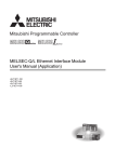
When connecting the Built-in Ethernet port QCPU with GX Developer, the direct connection (simple connection),
which connects them using only one Ethernet cable (not using a hub) is available. The direct connection enables
communication with only specifying connection target. IP address setting is not required.
Built-in Ethernet port QCPU
GX Developer
Ethernet cable
Figure 1.1 Direct connection (simple connection)
(3) MC protocol communication (
Section 3.3)
External devices such as personal computers and display devices read/write device data from/to the Built-in
Ethernet port QCPU. This enables external devices to monitor the operation of the CPU module, analyze data,
and manage production.
(4) Time setting function (SNTP client) (
Section 3.4)
• The time setting function enables automatic time setting for the Built-in Ethernet port QCPU, resulting in
reducing the maintenance cost for time setting.
• By synchronizing the Built-in Ethernet port QCPU connected via Ethernet, error occurrence order for each
process can be checked and troubleshooting becomes easy.
• Since time setting can be performed automatically at programmable controller CPU power ON, the CPU
module can start operation with accurate time data.
(5) File transfer function (FTP) (
Section 3.5)
An external device with a FTP client function can read/write files from/to the Built-in Ethernet port QCPU in units
of files, so that data such as in the program file and/or file register can be transferred easily.
(6) Remote password (
Section 3.6)
The Built-in Ethernet port QCPU can prevent unauthorized access from outside of the system and enhance the
security by setting the remote password.
1-1
CHAPTER2 COMMUNICATION SPECIFICATIONS
CHAPTER2 COMMUNICATION SPECIFICATIONS
Table2.1 shows the communication specifications for built-in Ethernet ports of the CPU module.
2
Table2.1 Ethernet communication specifications
Item
Specifications
Data transfer speed
100/10Mbps
Communication mode
Full-duplex/Half-duplex
Transmission method
Base band
Maximum distance between hub
Transmission
100m (328.08feet)
and node
specifications
Maximum
10BASE-T
Cascade connection: Four stages at maximum
100BASE-TX
Cascade connection: Two stages at maximum
number of
nodes/
connections
Number of
TCP/IP
connections
UDP/IP
10BASE-T
Cable used*1
100BASE-TX
16 for MELSOFT connections and MC protocols, 1 for FTP
Ethernet-compliant cable Category 3 or more (STP/UTP cable)*2
Ethernet-compliant cable Category 5 or more (STP cable)
*1 : Straight cables can be used.
Crossing cables can also be used for connecting the Built-in Ethernet port QCPU with GOT directly using an Ethernet
cable.
*2 : STP cables are recommended for the use under noisy environment.
Hubs with 10BASE-T or 100BASE-TX ports*3 can be used.
The maximum number of devices that can access to one CPU module simultaneously is 16.
*3 : The ports must comply with the IEEE802.3 10BASE-T or IEEE802.3 100BASE-TX standards.
●
When connecting with a hub, the Built-in Ethernet port QCPU determines the cable used (10BASE-T or 100BASE-TX)
and the communication mode (full-duplex or half-duplex).
Set the communication mode to the half-duplex mode on the hub side when the hub that does not have the autonegotiation function is used.
●
The module operation is not guaranteed if any of the following connection is used.
Check the module operation on the user side.
• Connections using the Internet (general public line) (Connections using Internet connection service provided by
Internet service providers and telecommunications carriers)
• Connections using devices in which a firewall is installed
• Connections using broadband routers
• Connections using wireless LAN
2-1
CHAPTER3 COMMUNICATION FUNCTION VIA BUILT-IN
ETHERNET PORTS OF CPU MODULE
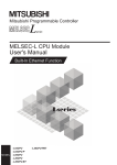
The Built-in Ethernet port QCPU can communicate data by connecting built-in Ethernet ports of the CPU module with
personal computers and/or display devices using an Ethernet cable (100BASE-TX, 10BASE-T).
Ethernet
Hub
GX Developer
MC protocol
FTP
GOT
Figure 3.1 Connection example using built-in Ethernet ports of CPU module
For the comparison with the conventional MELSEC-Q series Ethernet module (QJ71E71-100), refer to Appendix 1.
The following table lists the functions using built-in Ethernet ports of the CPU module.
Table3.1 List of functions
Function
3-1
Reference
GX Developer/GOT connection
Section 3.1
GX Developer direct connection (simple connection)
Section 3.2
MC protocol communication
Section 3.3
Time setting function (SNTP client)
Section 3.4
File transfer function (FTP server)
Section 3.5
Remote password
Section 3.6
CHAPTER3 COMMUNICATION FUNCTION VIA BUILT-IN ETHERNET PORTS OF CPU MODULE
3.1 GX Developer/GOT Connection
The following describes the setting method for connecting the Built-in Ethernet port QCPU with GX Developer and/or
GOT
3
Ethernet
Hub
GX Developer GX Developer
GOT
Figure 3.2 Connection example using hub
●
The Built-in Ethernet port QCPU can be connected directly with GX Developer using one Ethernet cable.
(Direct connection (simple connection))
The direct connection (simple connection) enables the QnUDE(H)CPU and GX Developer to communicate without
setting IP addresses. For details, refer to Section 3.2.
●
For setting on the GOT side, refer to following manual.
GOT1000 Series Connection Manual
3.1 GX Developer/GOT Connection
3-2
3.1.1 Setting for CPU module
The setting for the CPU module is described below.
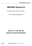
(1) PLC parameter setting
Set the items in the Built-in Ethernet port tab of the PLC parameter dialog box as shown in Figure 3.3.
2)
1)
Figure 3.3 Built-in Ethernet port tab
1) Set the CPU module IP address.
2) Set the connection for GX Developer (MELSOFT connection). (Refer to Figure 3.4)
Figure 3.4 Built-in Ethernet port open settings screen
• Protocol : Select the protocol to be used, "TCP" or "UDP" in accordance with the external device.
Select "TCP" to emphasize communication reliability.
• Open system : Select "MELSOFT connection".
(For the MELSOFT connection, refer to Section 3.3.)
• Host station port No. :Set the number when "MC Protocol" is selected.
3-3
CHAPTER3 COMMUNICATION FUNCTION VIA BUILT-IN ETHERNET PORTS OF CPU MODULE
(2) Operation for validating parameters
Using Ethernet direct connection or USB connection, write the settings in PLC parameter to the CPU module by
selecting [Online]
[Write to PLC] in GX Developer. After writing the parameter settings, power the
programmable controller OFF
ON or perform the reset operation of the CPU module using the RUN/STOP/
RESET switch so that the parameters become valid.
For the Ethernet direct connection, refer to the following section.
(
3
Section 3.2)
For the reset operation using the RUN/STOP/RESET switch, refer to the following manual.
QCPU Userís Manual (Hardware Design, Maintenance and Inspection)
3.1 GX Developer/GOT Connection
3.1.1 Setting for CPU module
3-4
3.1.2 Setting on GX Developer side
Setting on GX Developer side is described below.
1)
2)
3)
Figure 3.5 Transfer Setup screen
1) Select "Ethernet board" for "PC side I/F".
Select a protocol to be used in the Ethernet board setting screen as shown in Figure 3.6.
Figure 3.6 PC side I/F Ethernet board setting screen
• Network No., Station No.: Not used.
• Protocol: Select the protocol to be used, "TCP" or "UDP".
(Select the same protocol which has been set under the Open settings at Section 3.1.1.)
2) Select "PLC module" for "PLC side I/F".
Enter the IP address or host name of the CPU module in the Detailed setting of PLC module screen as
shown in Figure 3.7.
(For the host name, enter the name set in Microsoft
or Windows
hosts files.)
Figure 3.7 PLC side I/F Detailed setting of PLC module screen
3) Make the setting for "Other station".
3-5
CHAPTER3 COMMUNICATION FUNCTION VIA BUILT-IN ETHERNET PORTS OF CPU MODULE
The Find CPU function can be used for specifying the CPU IP address in the connection using a hub.
This function can be activated on the PLC side I/F Detailed setting of PLC module screen, finds the CPU modules connected
to the same hub as GX Developer, and displays a list.
3
Figure 3.8 PLC side I/F Detailed setting of PLC module screen
A list of the CPU modules found is displayed.
The IP address of the
corresponding CPU is input
automatically by clicking
the OK button.
Figure 3.9 Find CPU (Built-in Ethernet port) screen
Figure 3.10 Built-in Ethernet port tab
3-6
3.1 GX Developer/GOT Connection
3.1.2 Setting on GX Developer side
• CPU modules connected to a cascade connected hub are also found and displayed in the list.
• CPU modules connected via a router cannot be found.
• CPU modules connected via wireless LAN may not be found since the Ethernet communication does not stabilize
due to lost packets.
• If CPU modules with same IP address are found in the list, re-examine the parameter settings of the CPU IP
address. If communication is performed with the situation left as is, a communication error occurs.
• CPU modules may not be found if service processing load on CPU modules is heavy.
In that case, extend the response waiting time in the Find CPU (Built-in Ethernet port) screen as shown above, or
extend the service processing time in the PLC parameter dialog box.
• Select the checkbox as shown in Figure 3.10 in the Built-in Ethernet port tab of the PLC parameter dialog box so
that CPU modules to be searched do not respond on the network.
3.1.3 Precautions
The following are the precautions must be taken when connecting the Built-in Ethernet port QCPU with GX Developer
or GOT.
(1) Existence check using the KeepAlive function
When the protocol is set to "TCP", existence check using the KeepAlive function is performed.
The CPU module sends an existence check message five seconds after the last message from the external
device is received and waits to see whether a response from the external device is received.
If there is no response, the CPU module keeps sending an existence check message in five-second intervals.
When a response has not been confirmed within 45 seconds, the connection is disconnected, considering that no
external device exists.
The connection may be disconnected if the external device does not support the TCP KeepAlive function
(response to ACK messages for KeepAlive).
(2) Number of connections exceeding setting range
Establish connections within the number of protocols set for open settings of PLC parameter.
If TCP connections exceeding the set number of connections are made with a personal computer, the status of
some applications may change as described below.
• The status of application may change into the wait status, making the application inoperable.
• The time period causing a time-out error may increase.
(3) Retransmission processing in TCP connection
In TCP connection, if no ACK response message for TCP protocol is received from the external device,
retransmission processing is performed.
Resend processing is performed six times, 0.3, 0.6, 1.2, 2.4, 4.8, and 9.6 seconds after the first message.
If there is no ACK response within a period of 19.2 seconds after the last message is resent, the connection is
disconnected, considering that the external device is not operating normally.
(The connection is disconnected within the total period of 38.1 seconds.)
3-7
CHAPTER3 COMMUNICATION FUNCTION VIA BUILT-IN ETHERNET PORTS OF CPU MODULE
(4) Communication with MELSOFT devices in UDP protocol
To communicate with multiple MELSOFT devices using the UDP protocol, set the same number of protocols as
MELSOFT devices in PLC parameter.
3
Ethernet
Hub
Personal computer Personal computer
Personal computer
Set the same number
of protocols as MELSOFT
devices.
Figure 3.11 Setting for MELSOFT connection using UDP protocol
(5) Sampling trace
of the CPU module, stop the function before powering OFF the programmable controller or resetting the CPU
module.
(6) Remote STOP or remote PAUSE
To execute the remote STOP or remote PAUSE to a CPU module on another station using GX Developer which is
connected with built-in Ethernet ports of the CPU module, execute the remote STOP or remote PAUSE before
powering OFF the programmable controller or resetting the CPU module.
3-8
3.1 GX Developer/GOT Connection
3.1.3 Precautions
When the sampling trace function is executed using GX Developer which is connected with built-in Ethernet ports
3.1.4 Communication via routers
MELSOFT connection allows access to CPU modules on the network, such as internal LAN, via routers.
Routers
Internal RUN
Factory
Personal computer
Control room
Figure 3.12 Example of router use
When accessing a CPU module via routers, set the items in parameter as shown in Figure 3.13.
For other settings, refer to Section 3.1.1.
Set the Subnet mask
pattern and the Default
router IP address.
Figure 3.13 Built-in Ethernet port tab
3-9
CHAPTER3 COMMUNICATION FUNCTION USING BUILT-IN ETHERNET PORTS OF CPU MODULE
3.2 GX Developer Direct Connection (Simple Connection)
When connecting the Built-in Ethernet port QCPU with GX Developer, the direct connection (simple connection), which
connects them using only one Ethernet cable (not using a hub) is available.
The direct connection enables communication with only specifying connection target (Broadcasting). IP address
setting is not required.
3
GX Developer
Ethernet cable
Figure 3.14 Direct connection (simple connection)
When directly connecting the Built-in Ethernet port QCPU with GX Developer using an Ethernet cable, the wired cable is
longer than when using a USB cable. Therefore, the Built-in Ethernet port QCPU can be connected with a device located at
distant locations improperly.
Unauthorized connection to the Built-in Ethernet port QCPU can be prevented by selecting the checkbox as shown in Figure
3.15 in the Built-in Ethernet port tab of the PLC parameter dialog box.
3.2 GX Developer Direct Connection (Simple Connection)
Figure 3.15 Setting for preventing direct connection
3 - 10
3.2.1 Communication setting in GX Developer
Set the items on the Transfer Setup screen in GX Developer as shown in Figure 3.16.
1)
2)
3)
Figure 3.16 Transfer Setup screen
1) Select "Ethernet board" for "PC side I/F".
2) Select "PLC module" for "PLC side I/F".
Check the "Ethernet port direct connection" checkbox on the detailed setting screen as shown in Figure 3.17.
Figure 3.17 PLC side I/F Detailed setting of PLC module screen
3) Make the setting for "Other station".
3 - 11
CHAPTER3 COMMUNICATION FUNCTION USING BUILT-IN ETHERNET PORTS OF CPU MODULE
3.2.2 Precautions
The following are the precautions must be taken when directly connecting the Built-in Ethernet port QCPU with GX
Developer.
(1) Connection to LAN line
When the CPU module is connected to LAN line, do not perform communication using direct connection. If
performed, the communication may put a load to LAN line and adversely affect communications of other devices.
3
(2) Indirect connection
Do not select the "Ethernet port direct connection" checkbox in the Detailed setting of PLC module screen in the
system configuration that connects a Built-in Ethernet port QCPU with an external device using a hub as shown in
Figure 3.18.
Hub
Figure 3.18 Non-direct connection
(3) Conditions that disallow direct connection
Under the following conditions, direct connection communication may not be available. In that case, check the
setting of the CPU module and/or personal computer.
or all OFF.
Example
CPU module IP address
: 64. 64. 255. 255
Personal computer IP address
: 64. 64.
1.
1
Personal computer subnet mask
: 255. 255.
0.
0
2) In the CPU module IP address, bits corresponding to the host address for each class in the personal
computer IP address are all ON or all OFF.
Example
CPU module IP address
: 64. 64. 255. 255
Personal computer IP address
: 192. 168.
0.
1
Personal computer subnet mask
: 255.
0.
0
0.
Remark
●
The IP addresses for each class are described below.
Class A :0.x.x.x to 127.x.x.x
Class B :128.x.x.x to 191.x.x.x
●
The host addresses for each class are described below.
Class A :255. 0. 0. 0
Class B :255.255. 0. 0
Class C :192.x.x.x to 223.x.x.x
Class C :255.255.255. 0
3 - 12
3.2 GX Developer Direct Connection (Simple Connection)
3.2.2 Precautions
1) In the CPU module IP address, bits corresponding to "0" in the personal computer subnet mask are all ON
3.3 MC Protocol Communication
Built-in Ethernet ports of the Built-in Ethernet port QCPU enable communication using the MC protocol*1.
External devices such as personal computers and display devices read/write device data from/to the CPU module
using the MC protocol.
External devices monitor the operation of the CPU module, analyze data, and manage production by reading/writing
device data.
Besides, the remote password function can prevent unauthorized access to the CPU module from outside of the
system.(
Section 3.6)
*1 : The MC protocol is an abbreviation for the MELSEC communication protocol.
The MELSEC communication protocol is a name of the communication method used to access CPU modules from
external devices in accordance with the communication procedure of Q series programmable controllers (such as serial
communication modules, Ethernet modules).
For details on the MC protocol, refer to the following manual.
Q Corresponding MELSEC Communication Protocol Reference Manual
Personal computer, display device
Hub
Communication with MC protocol
Figure 3.19 MC protocol communication
External devices such as personal computers and display devices can communicate with only the connected CPU module
using the MC protocol.
An access to any of the following CPU modules is not available.
• CPU modules on another station via network
• Other CPU modules in a multiple CPU system
3 - 13
CHAPTER3 COMMUNICATION FUNCTION USING BUILT-IN ETHERNET PORTS OF CPU MODULE
3.3.1 Setting for MC protocol communication
Setting for communication using the MC protocol is described below.
Set the items of following (a) to (c) in the Built-in Ethernet port tab of the PLC parameter dialog box.
3
(c)
(a)
(b)
Figure 3.20 Built-in Ethernet port tab
(a) Communication data code
Select a communication data code used for the MC protocol, "Binary code" or "ASCII code".
(b) Enable online change (FTP, MC protocol)
Check the checkbox to enable online change when writing data to the CPU module from the external device
that communicates using the MC protocol.
For details on the available functions with this setting, refer to Section 3.3.2.
3.3 MC Protocol Communication
3.3.1 Setting for MC protocol communication
(c) Open settings
• Protocol :Select a connection used as MC protocol. (Up to 16 CPU modules can be connected.)
• Open system : Select "MC protocol".
• Host station port No. : Set the host station port number (in hexadecimal). (Required)
(Setting range : 0401H to 1387H, 1392H to FFFEH)
Figure 3.21 Open settings screen
When the "Enable online change (FTP, MC protocol)" box is unchecked, if a data write request is sent from an external
device to the CPU module which is in the RUN status, data will not be written to the CPU module and the module returns the
NAK message.
3 - 14
3.3.2 Command list
When the Built-in Ethernet port QCPU communicates using the MC protocol, commands listed in Table3.2 can be
executed.
Table3.2 List of MC protocol commands supported in MC protocol communication function of Built-in Ethernet port QCPU
Status of CPU module
Command
(Subcomm
and)*1
Function
Batch read
Batch write
Device
memory
Random
read *2
0401
(0001)
In units
of words
0401
(0000)
In units
of bits
1401
(0001)
In units
of words
1401
(0000)
Description
Reads bit devices in units of one point.
ASCII: 3584 points
BIN: 7168 points
Reads bit devices in units of 16 points.
960 words
(15360 points)
Reads word devices in units of one point.
960 points
Writes bit devices in units of one point.
ASCII: 3584 points
BIN: 7168 points
Writes bit devices in units of 16 points.
960 words
(15360 points)
Writes word devices in units of one point.
960 points
Reads bit devices in units of 16 or 32 points by
randomly specifying a device or device number.
In units
of words
0403
(0000)
In units
of bits
1402
(0001)
In units
of words
*2
1402
(0000)
Monitor
registration
*2*3*4
In units
of words
0801
(0000)
Monitor
In units
of words
0802
(0000)
Monitors devices registered.
Unlock
1630
(0000)
Specifies the remote password and changes the
status from locked to unlocked.
---
Lock
1631
(0000)
Specifies the remote password and changes the
status from unlocked to locked.
---
Test
(Random
write)
Remote
password
In units
of bits
Number of
processed points
Reads word devices in units of one or two points by
randomly specifying a device or device number.
Sets/resets bit devices in units of one point by
randomly specifying a device or device number.
Sets/resets bit devices in units of 16 or 32 points by
randomly specifying a device or device number.
Writes word devices in units of one or two points by
randomly specifying a device or device number.
Registers bit devices to be monitored in units of 16
or 32 points.
Registers word devices to be monitored in units of
one or two points.
RUN
STOP
Write
enabled
192 points
188 points
*5
192 points
Number of
registered points
: Available,
*1 : Subcommand is for the QnA-compatible 3E frame.
*2 : Devices such as TS, TC, SS, SC, CS, and CC cannot be specified in units of words.
For the monitor registration, an error (4032H) occurs during the monitor operation.
*3 : During monitor registration, monitor condition cannot be set.
*4 : Do not execute monitor registration from multiple external devices. If executed, the last monitor registration becomes valid.
*5 : Set the number of processed points so that the following condition is satisfied.
(Number of word access points)
12 + (Number of double-word access points)
14
1920
Bit devices are regarded as 16 bits during word access and 32 bits during double-word access.
Word devices are regarded as one word during word access and two words during double-word access.
3 - 15
Write
disabled
: Not available
CHAPTER3 COMMUNICATION FUNCTION USING BUILT-IN ETHERNET PORTS OF CPU MODULE
3.3.3 Available devices
Table3.3 lists the devices available in commands used in the MC protocol communication function.
Table3.3 List of available devices in Built-in Ethernet port QCPU
Classification
Internal system
device
internal user
device
Device
Special relay
Device code
Device number range(Default)
SM
000000 to 002047
Special register
SD
000000 to 002047
Decimal
Input
X
000000 to 001FFF
Hexadecimal
Output
Y
000000 to 001FFF
Hexadecimal
Internal relay
M
000000 to 008191
Decimal
Latch relay
L
000000 to 008191
Decimal
Annunciator
F
000000 to 002047
Decimal
Edge relay
V
000000 to 002047
Decimal
Link relay
B
000000 to 001FFF
Hexadecimal
Data register
D
000000 to 012287
Decimal
Link register
W
000000 to 001FFF
Hexadecimal
Timer
Retentive timer
Counter
Contact
TS
Coil
TC
Current value
TN
Contact
SS
Coil
SC
Current value
SN
Contact
CS
Coil
CC
Current value
000000 to 002047
Decimal
000000 to 002047
Decimal
000000 to 001023
Decimal
000000 to 0007FF
Hexadecimal
Link special register
SW
000000 to 0007FF
Hexadecimal
S
000000 to 008191
Decimal
Direct input
DX
000000 to 000FFF
Hexadecimal
Direct output
DY
000000 to 000FFF
Hexadecimal
Index register
Index register
Z
000000 to 000019
Decimal
File register
File register
R
000000 to 032767
Decimal
ZR
000000 to 3FD7FF
Hexadecimal
Extended link
register
Extended link register
• When the device number
range is changed, access is
possible up to the largest
device number after the
change.
• Local devices cannot be
accessed.
D
• Binary:
000000 to 4184063 (4086k
points maximum)
• ASCII:
000000 to 999999 (976.6k
points maximum)
W
000000 to 3FD7FF
(4086k points maximum)
3.3 MC Protocol Communication
3.3.3 Available devices
SB
Extended data register
3
---
CN
Link special relay
Step relay
Extended data
register
Remarks
Decimal
*1
---
Decimal
If the number of points is set on
the PLC file tab of PLC
parameter, access is possible
up to the largest device number
after the setting.
However, in the ASCII code
communication, the number of
points described on the left is
the access limit.
Hexadecimal
If the number of points is set on
the PLC file tab of PLC
parameter, access is possible
up to the largest device number
after the setting.
*1 : Devices of DX/DY1000 or later are not available. Use X/Y devices to access devices of X/Y1000 or later.
3 - 16
3.3.4 Precautions
(1) Number of connected modules
In the connection with external devices using the MC protocol, the number of CPU modules set as "MELSOFT
connection" in the open settings on Built-in Ethernet port tab of PLC parameter can be connected simultaneously.
(2) Data communication frame
Table3.4 shows the frames available in the Built-in Ethernet port QCPU.
Table3.4 Available frames in Built-in Ethernet port QCPU
Communication frame
Built-in Ethernet port QCPU
4E frame
QnA-compatible 3E frame
A-compatible 1E frame
(3) Access range
• Only connected CPU module can be accessed.
Accessing a CPU module not connected results in an error.
• In a multiple CPU system, other CPU modules not connected to Ethernet cannot be accessed.
• Accessing a CPU module on another station in CC-Link IE controller network, MELSECNET/H, Ethernet or
CC-Link via a connected CPU module is not possible.
(4) Precautions when UDP protocol is selected
• If a new request message is sent to the same UDP port while the port waits for a response message, the
new request message is discarded.
• Setting same host station port number to multiple UDP ports is regarded as one setting. When
communicating with multiple external devices using the same host station port number, select TCP protocol.
3 - 17
CHAPTER3 COMMUNICATION FUNCTION USING BUILT-IN ETHERNET PORTS OF CPU MODULE
(5) Response message receive processing
Figure 3.22 shows an example of the response message receive processing on the external device side.
Communication processing
on the external device side
3
Request message send processing
Response message receive processing
Is TCP connection open?
TCP connection is closed.
Receive the rest of
response messages.
Has the data
been received within the
monitoring timer?
The monitoring timer has run over.
The receive data exceeds
the size limit.
Check the receive data size.
Processing for response messages
The response message
for the following request
has been received.
Has processing
for all received messages
completed?
Error processing
Figure 3.22 Example of the response messages receive processing on the external device side
Remark
Personal computers use the TCP socket functions internally for Ethernet communication.
These functions do not have boundary concept. Therefore, when data is sent by executing the "send" function once, the
"recv" function needs to be executed once, twice or more to receive the same data.
(One execution of the "send" function does not correspond to one execution of the "recv" function.)
For this reason, receive processing described above is required on the external device side.
If the "recv" function is used in blocking mode, data may be read by executing the function once.
3 - 18
3.3 MC Protocol Communication
3.3.4 Precautions
End
3.3.5 Error codes for communication using MC protocol
Table3.5 shows the error codes, error descriptions, and corrective actions that will be sent from the CPU module to an
external device when an error occurs during communication using the MC protocol.
Table3.5 List of available devices in CPU module
No.
Error code
(Hexadecimal)
Description
CPU detected error (Error that occurred in other than
communication using the MC protocol)
Corrective action
Refer to the QCPU User's Manual (Hardware Design,
Maintenance and Inspection) and take corrective action.
1
4000H to 4FFFH
2
0055H
When the setting for online change is disabled on the Built-in
Ethernet port tab of PLC parameter in GX Developer, an
external device requested online change to the CPU module.
• When enabling online change, write data.
• Change the status of the CPU module to STOP and write
data.
3
C050H
When the communication data code setting is set to ASCII code
in the Built-in Ethernet port QCPU, ASCII code data that cannot
be converted to binary code was received.
• Set the communication data code to binary code and restart
the Built-in Ethernet port QCPU for communication.
• Correct the send data on the external device side and resend
the data.
4
C051H to C054H
The number of device points for reading/writing is outside the
allowable range.
Correct the number of device points for reading/writing and
resend the data to the Built-in Ethernet port QCPU.
Correct the start address or the number of device points for
reading/writing, and resend the data to the Built-in Ethernet port
QCPU.
(Do not exceed the allowable address range.)
Check and correct the text data or the request data length of the
header data, and resend the data to the Built-in Ethernet port
QCPU.
5
C056H
The read/write request data exceeds the allowable address
range.
6
C058H
The request data length after the ASCII to binary conversion
does not match the data size of the character area (a part of
text data).
7
C059H
• The command and/or subcommand are specified incorrectly.
• The command and/or subcommand not supported in the
Built-in Ethernet port QCPU are specified.
8
C05BH
The Built-in Ethernet port QCPU cannot read/write data from/to
the specified device.
Check the device for reading/writing data.
9
C05CH
The request data is incorrect. (ex. specifying data in units of bits
for reading/writing of word devices)
Correct the request data (such as subcommand correction) and
resend the data to the Built-in Ethernet port QCPU.
10
C05DH
Monitor registration is not performed.
Perform the monitor registration before monitor operation.
11
C05FH
The external device sent a request that cannot be executed in
the target CPU module.
12
C060H
The request data is incorrect. (ex. incorrect specification of data
for bit devices)
Correct the request data and resend the data to the Built-in
Ethernet port QCPU.
13
C061H
The request data length does not match the data size of the
character area (a part of text data)
Check and correct the text data or the request data length of the
header data, and resend the data to the Built-in Ethernet port
QCPU.
14
C06FH
The CPU module received a request message in ASCII when
the communication data code setting is set to binary code, or
received a request message in binary when the data code
setting is set to ASCII code.
(As for this error code, only error history is registered. The error
response message is not returned.)
15
C070H
The device memory extension cannot be specified for the target
station.
16
C0B5H
Data that cannot communicate in the CPU module or Ethernet
module is specified.
17
C200H
The remote password is incorrect.
Check the remote password and perform unlock/lock
processing again.
C201H
The communication target port is in the remote password
locked status.
Or, when the communication data code setting is set to ASCII
code, any data of subcommands and later cannot be converted
to binary code since the remote password is locked.
Perform remote password unlock processing before
communication.
18
3 - 19
• Check the request data.
• Use commands and/or subcommands supported in the Builtin Ethernet port QCPU.
• Correct the network number, PC number, request destination
module I/O number, and request destination module station
number.
• Correct the read/write request data.
• Send request messages corresponding to the communication
data code setting.
• Set the communication data code corresponding to the
request message.
Read/Write data to the device memory without specifying the
extension.
• Check the request data.
• Stop the current request.
CHAPTER3 COMMUNICATION FUNCTION USING BUILT-IN ETHERNET PORTS OF CPU MODULE
No.
19
Error code
(Hexadecimal)
C204H
Description
The external device is different from the one that quested
remote password unlock processing.
Corrective action
Have the same external device which has requested unlock
processing request remote password lock processing.
3
3.3 MC Protocol Communication
3.3.5 Error codes for communication using MC protocol
3 - 20
3.4 Time Setting Function (SNTP Client)
The Built-in Ethernet port QCPU collects time information from a time information server connected to LAN, making it
possible to set the CPU time automatically.
The Built-in Ethernet port QCPU time setting function queries a time information server to get the time at the specified
timing and sets the time sent from the time information server as clock data for the CPU module.
The time setting operation is executed based on the following timing.
• At programmable controller power ON or CPU module reset.
• Execution at a specified time interval (Execution interval)
• Execution at a specified time (Execution time)
• At special relay ON.*1
*1 : Time is set when the special relay (SM1270) is turned ON for one scan.
Querying a time server
to get the time
LAN
Setting the time in a server to the CPU
Ethernet
Personal computer
Figure 3.23 Image of time setting function
3 - 21
●
Check the connection of the hub or the external device first when executing a time setting operation at programmable
controller power ON or CPU module reset.
●
The time setting result details can be checked with the special registers (SD1270 to SD1275).
●
Other time setting operations are ignored during execution of the time setting function.
CHAPTER3 COMMUNICATION FUNCTION USING BUILT-IN ETHERNET PORTS OF CPU MODULE
3.4.1 Setting for time setting function
Set the time in the Built-in Ethernet port tab of the PLC parameter dialog box.
3
Figure 3.24 Time settings screen
Table3.6 Setting items on the time settings screen
Item
Description
SNTP
Select whether to use the time setting function. (Required)
SNTP server IP address
Specify the SNTP server IP address. (Required)
Specify the time zone in which the time is to be synchronized. (Required)
Default is set to Japan Standard Time "GMT + 9:00".
Execute time setting at turn ON/
Select whether to execute the time setting function when the programmable
reset
controller is powered ON or when the CPU module is reset.
Used or Not used
(GMT-12:00 to
GMT+13:00)
-
Select whether to stop or continue when a time setting error occurs when
At error occurrence
the programmable controller is powered ON or when the CPU module is
Continue or Stop
reset.
Execution interval *2
Execution time *2
Select to execute the time setting function at a specified time interval.
Select to execute the time setting function at a specified time.
(in increments of 30 minutes)
1 to 1440 min.
00:00 to 23:30
*2 : Either of the two options must be selected.
3 - 22
3.4 Time Setting Function (SNTP Client)
3.4.1 Setting for time setting function
Time zone
Setting range
3.4.2 Precautions
(1) Communication time-out
A communication time-out occurs when the Built-in Ethernet port QCPU has not received time information for 20
seconds from when querying a time information server.
Besides, when a communication time-out occurs, the value in SD1270 changes to 0FFFFH.
(2) Time information server
To use the time setting function, an SNTP server personal computer (time information server) is required on LAN.
(3) Delay resulted from the time required for communication
A delay occurs with respect to the time set in the CPU module as a result of the time required for communication
with the server. Specify the closest SNTP server possible on the network.
(4) For multiple CPU system configuration
In a multiple CPU system, enable the time setting function of only the Built-in Ethernet port QCPU No.1.
When a CPU module other than the Built-in Ethernet port QCPU No. 1 is enabled, the clock data of the Built-in
Ethernet port QCPU No. 1 is automatically set.
3 - 23
CHAPTER3 COMMUNICATION FUNCTION USING BUILT-IN ETHERNET PORTS OF CPU MODULE
3.5 File Transfer Function (FTP)
The Built-in Ethernet port QCPU supports the FTP (File Transfer Protocol) server function. FTP is a protocol for
transferring files between CPU modules and external devices.
An external device with a FTP client function can simply access to files within the CPU module directly by using this
FTP server function.
3
Built-in Ethernet port QCPU (FTP server)
Parameter
Program
Data
External device (FTP client)
Storage file
Read
Write
Ethernet
Figure 3.25 File transfer function (FTP)
The following accesses can be performed to files in the Built-in Ethernet port QCPU from an external device with a
FTP client function.
(a) Reading (downloading) files from Built-in Ethernet port QCPU
A function for storing CPU module files in an external device.
(b) Writing (uploading) files to Built-in Ethernet port QCPU
3.5 File Transfer Function (FTP)
A function for registering files stored in an external device to the CPU module.
(c) Browsing Built-in Ethernet port QCPU file names
A function for checking files registered in the CPU module on the external device side.
In a multiple CPU system, only the CPU module connected with an Ethernet cable can transfer files.
3 - 24
3.5.1 Setting for FTP communication
Setting for communication using the FTP is described below.
(1) Operation for CPU module
Set the items in the Built-in Ethernet port tab of the PLC parameter dialog box.
(c)
(a)
(b)
Figure 3.26 Built-in Ethernet port tab
(a) IP address
Set an IP address for CPU module.
(b) Enable online change (FTP, MC protocol)
Check this checkbox to enable online change.
(c) FTP setting
Set the FTP parameters as shown below.
Figure 3.27 FTP settings screen
Table3.7 Setting items on the FTP settings screen
Item
FTP
Log-in name
Set the login name for an external device to request file transfer (log in).
Password
Set the FTP password for an external device to request file transfer (log in). To change the password, enter both the old
and the new passwords for confirmation.
Command input
monitoring timer
3 - 25
Description
Set to "Used".
Set the monitoring time for command input performed by the CPU module. When no command is input within the set
period of time, the FTP connection is disconnected. (Setting range : 1 to 32767 (
time will be larger than the time required for file transfer.
500ms)) Set the value so that the
CHAPTER3 COMMUNICATION FUNCTION USING BUILT-IN ETHERNET PORTS OF CPU MODULE
Remark
To access the CPU module via a router, set the "Subnet mask pattern" and the "Default router IP address" settings as
well.(
Section 3.1.4)
(2) Operation on external device (FTP client) side
The procedure and required processing on the external device side when using the FTP server function of Built-in
3
Ethernet port QCPU are described below.
FTP operation commands used in each operation and their input methods are also described.
(<ret> indicates an input of the CR, Enter or Return key.)
Start
Start up FTP client.
(ftp<ret>)
Log-in to the QnUDE(H)CPU. (open IP address of the QnUDE(H)CPU<ret>)
NO
Is the FTP
targeted for the remote
password check?
YES
Unlock the remote password. (quote password-unlock Remote password<ret>)
Has the file
transfer operation
completed?
YES
NO
Is the FTP
NO
targeted for the remote
password check?
YES
File write
File read or file write?
File read
Notify that the file will
not be converted.
Check the file list in the CPU. (dir<ret> or Is<ret>)
(quote password-lock
Lock the remote password. <ret>)
NO
Notify that the file will
not be converted.
NO
Does the write
target file exist?
NO
3.5 File Transfer Function (FTP)
3.5.1 Setting for FTP communication
Does the read
target file exist?
(binary<ret>)
Check the file list in the CPU. (dir<ret> or Is<ret>)
YES
Disconnect the connection (bye<ret>)
with the QnUDE(H)CPU.
End
(binary<ret>)
YES
Is a file
password set for
the target file?
Is it OK to overwrite?
NO
YES
YES
Enter the file password.
(quote keyword-set
File password<ret>)
Read the file.
(get File name<ret>)
NO
Is a file
password set for
the target file?
YES
Enter the file password.
(quote keyword-set
File password<ret>)
(delete File name<ret>
Delete the file with the same
name. Or change the file name. rename Current file name
New file name<ret>)
Write the file.
(put File name<ret>)
Figure 3.28 FTP client side operation procedure
3 - 26
(a) Logging in to Built-in Ethernet port QCPU
Operations from starting the FTP to logging in to the Built-in Ethernet port QCPU are described below.
Example) Start up the FTP from the MS-DOS prompt of a Microsoft
Windows
XP Operating System.
1
2
3
3
Figure 3.29 Example of screen for logging in to Built-in Ethernet port QCPU
Start FTP (FTP<ret>)
Connect to FTP server (open Built-in Ethernet port QCPU IP address<ret>)
Specify login name (Login name (Default: QNUDECPU)<ret>)
Specify password (Password (Default: QNUDECPU)<ret>)
(b) Unlocking/Locking remote password
When the FTP communication port is specified for a remote password check target in remote password
settings, the remote password needs to be unlocked using the following command.
(quote password-unlock Remote password<ret>)
At the end of the operation, change the remote password to the locked status using the following command.
(quote password-lock<ret>)
When the FTP communication port is specified for a remote password check target in remote password settings, other
commands cannot be used until the remote password is unlocked.
(c) Entering file password
When a file password is set for the target file, the file password needs to be entered using the following
command before accessing the file.
(quote keyword-set File password<ret>)
3 - 27
CHAPTER3 COMMUNICATION FUNCTION USING BUILT-IN ETHERNET PORTS OF CPU MODULE
3.5.2 List of transferable files
Table3.8 lists the transferable files using the file transfer function.
Table3.8 List of transferable files
Target memory
File storage drive
number
0
Program
File type
Memory
Built-in memory
memory
*2 *3
card (RAM)
3
4
1
Standard
Standard
SRAM card
RAM
ROM *4
*4
Memory card (ROM)
2
2
File name or
3
extension
Flash card
ATA card *4
Parameter
PARAM.QPA
Intelligent function module
parameter
IPARAM.QPA
Program
.QPG
Device comment
.QCD
Device initial value
.QDI
Device data
.QST
File register
.QDR
Local device
.QDL
Sampling trace file
.QTD
Error history data
.QFD
Programmable controller user
Arbitrary file
name
data *1
-
:Transferable,
:Not transferable
*1 : A file for reading/writing data by a sequence program using the following instructions:
SP.FREAD (Batch-reads data from the specified file in the memory card.)
SP.FWRITE (Batch-writes data to the specified file in the memory card.)
For details on the SP.FREAD/SP.FWRITE instructions, refer to the following manual.
QCPU Programming Manual (Common Instructions)
*2 : Writing files to the program memory is enabled only when the CPU module is in the STOP status.
*3 : Write destination is the program cache memory.
The user should back up files using the "pm-write" command as required.(
Section 3.5.5)
*4 : The number of files written using the File transfer function (FTP) is up to the number described below.
[The maximum number of files can be stored in the corresponding drive -1]
3 - 28
3.5 File Transfer Function (FTP)
3.5.2 List of transferable files
User setting area
3.5.3 List of FTP commands
Table3.9 lists the FTP client commands can be used in the Built-in Ethernet port QCPU.
Table3.9 List of FTP client side user interface commands
CPU module status
Remote password
RUN
Command
Function
binary
Notifies that a file is to be transferred to the FTP server without conversion.
bye
Disconnects the FTP server connection and ends the FTP function.
close
Disconnects the FTP server connection.
delete
Deletes a file stored in the Built-in Ethernet port QCPU.
dir
Displays file information stored in the Built-in Ethernet port QCPU.
get
Reads a file from the Built-in Ethernet port QCPU.
ls
Displays the file names of files stored in the Built-in Ethernet port QCPU.
mdelete
Deletes a file stored in the Built-in Ethernet port QCPU.
mdir
Saves information of files stored in the Built-in Ethernet port QCPU.
mget
Reads a file from the Built-in Ethernet port QCPU.
mls
Saves names of files stored in the Built-in Ethernet port QCPU.
mput
Writes a file to the Built-in Ethernet port QCPU.
open
Connects to the FTP server.
put
Writes a file to the Built-in Ethernet port QCPU.
pwd
Displays the current directory name of the Built-in Ethernet port QCPU.
STOP
Write
enabled
Write
disabled
*1
*1
Unlocked
Locked
*2
*2
Remarks
-
quit
Disconnects the FTP server connection and ends the FTP function.
quote
Sends an FTP server subcommand.
rename
Renames a Built-in Ethernet port QCPU file.
user
Inputs the user name and password of Built-in Ethernet port QCPU.
*3
-
: PerformableI,
: Not performable
*1 : These indicate the online change enable and disable settings made in the Built-in Ethernet port tab of the PLC parameter dialog box.
*2 : These indicate the remote password execution status when FTP communication port specified for remote password check target on the
Remote password detail settings screen in GX Developer.
For details of the remote password, refer to Section 3.6.
*3 : Table3.10 lists the subcommands that can be used with the "quote" command.
3 - 29
CHAPTER3 COMMUNICATION FUNCTION USING BUILT-IN ETHERNET PORTS OF CPU MODULE
Table3.10 Subcommands that can be used with "quote" command
CPU module status
Command
Function
change
Displays/changes the Built-in Ethernet port QCPU file attribute.
keyword-set
Sets/displays/clears the Built-in Ethernet port QCPU file
access password.
password-lock
Specifies the remote password and changes the status from
unlocked to locked.
password-unlock
Specifies the remote password and changes the status from
locked to unlocked.
status
Displays the operation information of the Built-in Ethernet port
QCPU.
run
Changes the Built-in Ethernet port QCPU status to RUN.
stop
Changes the Built-in Ethernet port QCPU status to STOP.
pm-write
Writes files to the program memory.
Remote password
RUN
STOP
Write
enabled
Write
disabled
Unlocked
Locked
Remarks
3
*1
-
: PerformableI,
: Not performable
*1 : Even if the subcommand is executed, the remote password status remains locked and an error does not occur.
3.5 File Transfer Function (FTP)
3.5.3 List of FTP commands
3 - 30
3.5.4 How to read FTP commands
(1) FTP command descriptions
The FTP operation commands (on the FTP client (external device) side) which can be used in the Built-in
Ethernet port QCPU are described below.
How to read descriptions
Sections in brackets at [Specification format] can be omitted.
(2) File specification methods
File specification method which is specified during execution of an FTP operation command (on the FTP client
side) is described below.
• For the Built-in Ethernet port QCPU, files are specified using drive names and file names.
• When specifying a file in the Built-in Ethernet port QCPU using the FTP function, specify the target file in the
following order.
[Specification format]
Drive name : \ File name . extension
[Specification example] 3:\MAINSEQ1.QDR
[Specification details]
Refer to the following 1) and 2).
1) Drive name (Drive No.)
Specify the drive name of the file transfer target memory.
For the correspondence between Built-in Ethernet port QCPU target memory and drive name, refer to
Table3.8.
2) File name, extension
• Specify the file transfer target file.
• Specify the file name according to the rules for naming files using GX Developer.
Characters that can be used are one-byte alphabets (uppercase), numbers, and symbols. Lowercase
alphabets cannot be used.
File name
: 8 characters maximum (one-byte)
Extension
: 3 characters maximum (one-byte)
Alphabets are not case-sensitive. Lowercase alphabets are treated as uppercase alphabets.
• For the extension, the name fixed by the Built-in Ethernet port QCPU must be used.
Specify the extension for the target file in accordance with Table3.8.
• For details of the file names and extensions, refer to the following manual.
GX Developer Version 8 Operating Manual
• When using FTP operation commands which can target multiple files, specify the file names and
extensions within the file path name using a wild card (* and/or ?).
* : Used for specifying all files having arbitrary characters (including no characters) after the location
where "*" is used.
? : Used for specifying all files having arbitrary characters (including no characters) at the location
where the "?" is used. (Multiple "?" can be used.)
Some FTP clients have restrictions on characters that can be used for file names other than those
described above.
3 - 31
CHAPTER3 COMMUNICATION FUNCTION USING BUILT-IN ETHERNET PORTS OF CPU MODULE
3.5.5 Detail of FTP commands
Functions and usages of FTP operation commands (on the FTP client side) which can be used in the Built-in Ethernet
port QCPU are described below.
Note that some FTP operation commands (on the FTP client side) which can be used in the Built-in Ethernet port QCPU
may not operate as described in this manual, depending on the FTP application used on the FTP client side.
Check the functions and operation methods, referring to the manuals on the FTP client side.
3
(1) FTP server support commands
binary
[Function]
Notifies that a file is to be transferred to the FTP server without conversion.
Neither return codes nor kanji codes are converted.
This command is set automatically in the Built-in Ethernet port QCPU.
[Specification format]
binary (abbreviated format bin)
bye
[Function]
Disconnects the FTP server connection and ends the FTP function.
[Specification format]
bye
[Identical function]
quit
[Function]
Disconnects the FTP server connection.
[Specification format]
close
3.5 File Transfer Function (FTP)
3.5.5 Detail of FTP commands
close
delete
[Function]
Deletes a file stored in the Built-in Ethernet port QCPU.
[Specification format]
delete File path name
[Specification example]
When deleting a file stored in the ATA card
[Similar function]
mdelete
delete2:\MAINSEQ1.USR
dir
[Function]
Displays the names, created dates, and sizes of files stored in the Built-in Ethernet port
QCPU.
[Specification format]
dir [Drive name:\]
[Specification example]
When displaying the detailed information of files stored in the RAM area of the memory card
[Similar function]
ls
dir1:\
3 - 32
get
[Function]
Reads a file from the Built-in Ethernet port QCPU.
[Specification format]
get Transfer source file path name [Transfer destination file path name]
[Specification example1]
When reading a file stored in the SRAM card and saving that file under the same file name
get1:\MAINSEQ1.QDR
[Specification example2]
When reading a file stored in the SRAM card and saving that file under a different file name
get1:\SEQ1BAK.QDR\SEQ10LD.QDR
[Note]
• When the transfer destination file path name (FTP client side) is not specified, the file is
saved on the FTP client side using the same file name as the transfer source file name
(Built-in Ethernet port QCPU side).
• The transfer destination is on the current directory of which when FTP is started up and
connected to the server.
ls
[Function]
Displays the names of files stored in the Built-in Ethernet port QCPU.
[Specification format]
Is [Drive name:\]
[Specification example]
When displaying the names of files stored in the SRAM card
[Similar function]
dir
ls1:\
mdelete
[Function]
Deletes a file stored in the Built-in Ethernet port QCPU.
To delete multiple files, specify the file names and extensions within the file path name using
a wild card (* and/or ?).
[Specification format]
mdelete File path name (abbreviated format: mdel)
[Specification example]
When deleting all files whose extensions are "QPG" among the files stored in the ATA card
[Similar function]
delete
mdelete2:\*.QPG
mdir
[Function]
Saves detailed information (file names, created dates, and sizes) of files stored in the Builtin Ethernet port QCPU as log data in a file on the FTP client side.
[Specification format]
mdir Transfer source drive name:\ Transfer destination file path name
[Specification example]
When saving detailed information of files stored in the SRAM card to the S990901.LOG file
mdir1:\S990901.LOG
[Note]
• Specify "\" immediately after the transfer source drive name.
• Specify the transfer source drive name when specifying the transfer destination file path
name (FTP client side).
• When the transfer destination file path name is not specified, the file is saved using a file
name determined by the FTP application on the FTP client side.
• The transfer destination is on the current directory of which when FTP is started up and
connected to the server.
[Similar function]
3 - 33
mls
CHAPTER3 COMMUNICATION FUNCTION USING BUILT-IN ETHERNET PORTS OF CPU MODULE
mget
[Function]
Reads a file from the Built-in Ethernet port QCPU.
To read multiple files, specify the file names and extensions within the file path name using
a wild card (* and/or ?).
When reading multiple files, receive status is checked for each file transfer.
[Specification format]
mget File path name
[Specification example]
When reading all files whose extensions are "USR" among the files stored in the ATA card
mget2:\*.USR
[Note]
The read file is saved on the FTP client side under the same file name.
3
The save destination is on the current directory of which when FTP is started up and
connected to the server.
mls
[Function]
Saves the names of files stored in the Built-in Ethernet port QCPU as log data in a file on the
FTP client side.
[Specification format]
mls Transfer source drive name:\ Transfer destination path name
[Specification example]
When saving the names of files stored in the SRAM card to the S990901F.LOG file
mls1:\S990901F.LOG
[Note]
• Specify "\" immediately after the transfer source drive name.
• Specify the transfer source drive name when specifying the transfer destination file path
name (FTP client side).
• When the transfer destination file path name is not specified, the file is saved using a file
name determined by the FTP application on the FTP client side.
• The transfer destination is on the current directory of which when FTP is started up and
connected to the server.
[Similar function]
mdir
[Function]
Writes a file to the Built-in Ethernet port QCPU.
To write multiple files, specify the file names and extensions within the file path name using
a wild card (* and/or ?).
When writing multiple files, send status is checked for each file transfer.
[Specification format]
mput Transfer source file path name
[Specification example]
When writing all files whose extensions are "USR"
mput*.USR
[Note]
The save destination file name is the same as that on the FTP client side.
The transfer destination is the memory in which the parameter files used during the current
operation are stored.
open
[Function]
Connects to the FTP server based on a specified host name or IP address and port number
on the FTP server side.
[Specification format]
open Host name [Port number]
open IP address [Port number]
• Host name : Host name set in Microsoft
Windows
hosts file
• IP address: Built-in Ethernet port QCPU IP address
• Port number: Port number to be used
[Specification example1]
When connecting to the FTP server by specifying a host name
[Specification example2]
When connecting to the FTP server by specifying an IP address
open HOST
open 192.0.1.254
[Note]
Connection is also possible by specifying an IP address when FTP is started up.
3 - 34
3.5 File Transfer Function (FTP)
3.5.5 Detail of FTP commands
mput
put
[Function]
Writes a file to the Built-in Ethernet port QCPU.
[Specification format]
put Transfer source file path name [Transfer destination file path name]
[Specification example1]
When writing the MAINSEQ1.QDR file to the SRAM card with the same file name
put MAINSEQ1.QDR1:\MAINQDR1.QDR
[Specification example2]
When writing the MAINSEQ.QDR file to the SRAM card with a different file name
put MAINSEQ.QDR1:\MAINQDR1.QDR
[Note]
• When the transfer destination file path name (FTP client side) is not specified, the files on
the current directory of which when FTP is started up and connected to the server are
written.
• When the transfer destination file path name (FTP server side) is not specified, the files
are saved in the memory in which the parameter files used during the current operation
are stored.
pwd
[Function]
Displays the current directory name of the Built-in Ethernet port QCPU.
[Specification format]
pwd
[Note]
"\" is displayed as the execution result of the "pwd" command.
quit
[Function]
Disconnects the FTP server connection and ends the FTP function.
[Specification format]
quit
[Identical function]
bye
quote
[Function]
Sends an FTP server subcommand (Built-in Ethernet port QCPU dedicated subcommand).
[Specification format]
quote
[Specification example]
quote password-lock
[Note]
Only Built-in Ethernet port QCPU dedicated subcommands can be specified. Refer to (2).
rename
[Function]
Renames a Built-in Ethernet port QCPU file.
[Specification format]
rename Old file path name New file path name (abbreviated format: ren)
[Specification example]
When renaming a file stored in the SRAM card
[Note]
The following response codes are displayed upon normal completion.
rename 1:\MAINSEQ1.QDR1:\SEQ1OLD.QDR
350 Need more info.
250 Rename successful.
user
[Function]
Inputs the user name and password of the connected FTP server.
[Specification format]
user User name [FTP password]
• User name: Login name set in Built-in Ethernet port QCPU parameter
• FTP password: FTP password set in Built-in Ethernet port QCPU parameter
[Specification example1]
When specifying a user name
user CPU
[Specification example2]
When specifying a user name and password
user CPU CPU
3 - 35
CHAPTER3 COMMUNICATION FUNCTION USING BUILT-IN ETHERNET PORTS OF CPU MODULE
(2) Built-in Ethernet port QCPU dedicated subcommands
The Built-in Ethernet port QCPU dedicated subcommands added to and sent with the FTP operation "quote"
command are described below.
change
[Function]
Displays/changes Built-in Ethernet port QCPU file attribute.
[Specification format1]
When displaying file attribute
3
quote change File path name
One of the following is displayed as the execution result upon normal completion.
• When the specified file is a read-only file
: ----- R
• When the specified file is a read/write-enabled file : ----- W
[Specification format2]
When changing file attribute
quote change File path name Attribute
Use one of the following for specifying the attribute.
• To change the file to read-only file
:r
• To change the file to a read/write-enabled disk file : w
[Specification example1]
When displaying file attribute stored in the SRAM card
[Specification example2]
When changing file attribute stored in the SRAM card
quote change 1:\MAINSEQ1.QDR
quote change 1:\MAINSEQ1.QDR r
keyword-set
[Function]
Sets a file password registered in the file transfer target file into the Built-in Ethernet port
QCPU.*1
Or, displays/clears the password set for FTP settings in parameter.
[Specification format]
quote keyword-set [File password]
To clear the set file password, specify "****".
One of the following is displayed as the execution result upon normal completion.
• When setting a file password
: 200 Command successful
• When displaying a file password: 200 Keyword is "File password"
• When clearing a file password
: 200 Command successful
[Specification example1]
When setting the password (1234)
[Specification example2]
When displaying the password currently set for FTP settings in parameter
[Specification example3]
When clearing the password currently set for FTP settings in parameter
quote keyword-set 1234
quote keyword-set
quote keyword-set ****
[Note]
• One file password can be set for the FTP settings in Built-in Ethernet port QCPU
parameter.
When the file targeted for file transfer changes, re-set the file password of the target file
when a file password is also registered for the change target file.
• When logging in to the Built-in Ethernet port QCPU, the file password is initialized
(cleared) to "****".
* 1 : This command is used only when a file password is registered in the file transfer target file. When accessing the specified
file, the Built-in Ethernet port QCPU checks the file password.
3 - 36
3.5 File Transfer Function (FTP)
3.5.5 Detail of FTP commands
• File password :Specify the file password registered in the Built-in Ethernet port QCPU file.
password-unlock
[Function]
Specifies the remote password set in the Built-in Ethernet port QCPU and performs unlock
processing.*2
[Specification format]
quote password-unlock [Remote password]
• Remote password: Specify the remote password set in Built-in Ethernet port QCPU
parameter.
The following is displayed as the execution result upon normal completion.
200 Command 0key
The following is displayed when the entered remote password and set remote password do
not match.
556 Password Error
The following is displayed when another command is requested before unlock processing of
the remote password is performed.
555 Password Locked
[Specification example]
When specifying the remote password (1234)
quote password-unlock 1234
[Note]
• The remote password is locked when logged in to the Built-in Ethernet port QCPU if the
FTP communication port is specified for a remote password check target.
• Performing unlock processing by executing this command before the various FTP
operations enables file operations in the Built-in Ethernet port QCPU.
• Processing completes normally if the remote password unlock processing is performed
when the FTP communication port is not specified for a remote password check target.
*2 : This command is used only when FTP communication port is specified for a remote password check target.
password-lock
[Function]
[Specification format]
Performs lock processing of the remote password set in the Built-in Ethernet port QCPU.*3
quote password-lock
The following is displayed as the execution result upon normal completion.
200 Command 0key
[Specification example]
When locking the remote password
quote password-lock
*3 : This command is used only when FTP communication port is specified for a remote password check target.
3 - 37
CHAPTER3 COMMUNICATION FUNCTION USING BUILT-IN ETHERNET PORTS OF CPU MODULE
run
[Function]
Changes the Built-in Ethernet port QCPU status to RUN. (Executes remote RUN.)
When changing the Built-in Ethernet port QCPU status to RUN, device memory clear can be
specified.
[Specification format]
quote run [Mode [Clear mode]]
• Mode: Specify whether to execute remote RUN forcibly.
0 : Normal RUN (default)
3
1 : Forced RUN
• Clear mode:
Specify the clear (initialization) processing of the Built-in Ethernet port QCPU device
memory when an operation starts by executing remote RUN.
0 : Do not clear device (default)
1 : Clear all devices excluding latch range
2 : Clear all devices including latch range
The following message is displayed as the execution result upon normal completion.
200 Command successful
[Specification example1]
When executing remote RUN, specifying "Normal RUN" and "Do not clear device"
[Specification example2]
When executing remote RUN, specifying "Forced RUN" and "Do not clear device"
[Specification example3]
When executing remote RUN, specifying "Forced RUN" and "Clear all devices excluding
quote run
quote run 1
latch range"
quote run 1 1
[Note]
• Forced RUN mode is used to forcibly execute remote RUN to the Built-in Ethernet port
QCPU from other devices when a trouble occurs in the device which executed remote
STOP to the Built-in Ethernet port QCPU (the device can no longer execute remote RUN
to the Built-in Ethernet port QCPU).
When Normal RUN mode is specified, the status will not change to RUN if the Built-in
Ethernet port QCPU is already set in the STOP/PAUSE status by another device.
After the specified clear processing is performed, the Built-in Ethernet port QCPU
changes to the RUN status in accordance with the parameter settings ("Initial Device
value" setting on the PLC file tab of PLC parameter).
status
[Function]
Displays the operation information of the Built-in Ethernet port QCPU.
This command checks the Built-in Ethernet port QCPU operation information when
executing file transfer to the Built-in Ethernet port QCPU.
[Specification format]
quote status
One of the following is displayed as the execution result upon normal completion.
• When the Built-in Ethernet port QCPU is in the RUN status: "RUN"
• When the Built-in Ethernet port QCPU is in the STOP status: "STOP"
• When the Built-in Ethernet port QCPU is in the PAUSE status: "PAUSE"
3 - 38
3.5 File Transfer Function (FTP)
3.5.5 Detail of FTP commands
• Specify the clear mode at the start of an operation based on the system arrangement.
stop
[Function]
Changes the Built-in Ethernet port QCPU status to STOP. (Executes remote STOP.)
[Specification format]
quote stop
The following message is displayed as the execution result upon normal completion.
200 Command successful
[Note]
Write files to the program memory after the Built-in Ethernet port QCPU status is changed to
STOP using this command.
pm-write
[Function]
Transfers files in the program cache memory to the program memory.
[Specification format]
quote pm-write
The following message is displayed as the execution result upon normal completion.
200 Command successful
[Note]
3 - 39
Write files after the Built-in Ethernet port QCPU status is changed to STOP.
CHAPTER3 COMMUNICATION FUNCTION USING BUILT-IN ETHERNET PORTS OF CPU MODULE
3.5.6 Precautions
Precautions for using the file transfer function are described below.
(1) FTP clients
• FTP command specifications may differ from those described in this manual, depending on the FTP client. In
such a case, check the functions and operation methods, referring to the manuals on the FTP client side.
• FTP operations cannot be performed from Microsoft
3
Internet Explorer. If performed, an error occurs with
Internet Explorer.
(2) Processing in Built-in Ethernet port QCPU
• Files only in the drives of the host station Built-in Ethernet port QCPU can be accessed.
• During file access, do not turn OFF the power supply, reset the CPU module or install/remove a memory
card. If any of these operations are performed, files may corrupt.
• During file access, do not perform any file operations from peripherals such as GX Developer. When a file
operation is performed from another peripheral during FTP function operation, an error may occur on the
peripheral side.
• During online change, do not perform any file operations using the FTP function. When a file operation is
performed, an error may occur.
• During file access using the FTP function, do not perform any online operations from peripherals such as GX
Developer. When an online operation is performed, an error may occur on the peripheral side.
• During backup or restoration of the CPU module change function using a memory card, an error occurs in
file access from FTP clients.
In that case, access the file again after the backup or restoration operation is completed.
Moreover, if the backup or restoration operation is performed during file access from FTP clients, an error
In that case, perform the backup or restoration operation again after blocking the communication with FTP
clients.
(3) Communication processing
• When a time-out error occurs during file transfer, the TCP connection will be closed (disconnected). To
restart the file transfer, log in to the Built-in Ethernet port QCPU once again from an FTP client.
• In a communication using FTP connections, an existence check of external devices is performed. For
operation details, refer to Section 3.1.3.
• The file transfer processing time depends on the following factors.
1) Load rate of the Ethernet line (line traffic)
2) Number of connections simultaneously used (communication processing of other connections)
3) System configuration
• The number of external devices (FTP clients) that can be simultaneously logged in to the Built-in Ethernet
port QCPU is only one. When another FTP client attempts the connection to the Built-in Ethernet port QCPU
which is in the logged-in status, connection cannot be established and an error occurs.
• If the File transfer function using the FTP is executed simultaneously with other communication functions
(MELSOFT connection, MC protocol) using the UDP, an error, such as a time-out error, may occur. Execute
other communication functions after file transfer is completed or communicate using the TCP.
3 - 40
3.5 File Transfer Function (FTP)
3.5.6 Precautions
occurs.
(4) Precautions for writing files
• Operation to overwrite an existing file cannot be performed.
Either delete the file using a file delete command (delete, mdelete) or rename the file using a file name
change command (rename) before writing the file.
• Files whose attribute is read-only or files which are locked by other devices/functions cannot be written. If
files are written, a write error occurs.
• File transfer (writing files) cannot be executed when a write-protected memory card is used. If files are
written, a write error occurs.
• When a file is written, a temporary file (FTP_I***.TMP) is created automatically. The name of this file is
changed to the name of written file upon normal completion. However, if the power failure or reset of the
CPU module occurs during the file write, this temporary file may remain. If this occurs, delete the temporary
file.
• When file registers are used in the standard RAM or SRAM card, change the CPU status to STOP first, and
then write /delete files to/in these drives.
• When file registers used in the standard RAM or SRAM card are set as auto refresh devices, do not write/
delete files to/in these drives.
• If large-capacity files are written to the ATA card during RUN, a load on write processing increases and a
communication error may occur. Change the CPU status to STOP to write large-capacity files.
(5) Precautions for deleting files
• The timing for deleting files is to be arranged by the user considering the overall system, including Built-in
Ethernet port QCPU and GX Developer.
• Files whose attribute is read-only or files which are locked by other devices/functions cannot be deleted. If
files are deleted, a delete error occurs.
• Deleting files cannot be executed when a write-protected memory card is used. If files are deleted, a delete
error occurs.
3 - 41
CHAPTER3 COMMUNICATION FUNCTION USING BUILT-IN ETHERNET PORTS OF CPU MODULE
3.6 Remote Password
This function checks a remote password when the communication using the following connections is requested.
• Communication using GX Developer
• Communication using the MC protocol
• File transfer
3
The remote password function is a function to prevent unauthorized access (ex. corrupting data and programs) from external
devices.
However, this function cannot completely prevent unauthorized access.
Users should incorporate safety measures by themselves if security of the programmable controller system needs to be
maintained against unauthorized access from external devices. We cannot be held responsibility for any problems caused
by unauthorized access.
[Examples of measures against unauthorized access]
• Install a firewall.
• Set up a personal computer as a relay station and control the relay of communication data using an application
program.
• Set up an external device that control access authority as a relay station.
Please consult a network provider or equipment sales company regarding external devices that can control
access authority.
3.6 Remote Password
3 - 42
3.6.1 Communication method when a remote password is set
The communication procedure with the Built-in Ethernet port QCPU with a preset remote password is described below.
(1) Access enable processing (unlock processing)
An external device such as a personal computer performs remote password unlock processing for the CPU
module.
When unlock processing is not performed, an error occurs in the external device since the CPU module does not
accept access.
(2) Access processing
Access is enabled after the remote password unlock processing is completed normally.
(3) Access disable processing (lock processing)
Remote password lock processing is performed from the external device to disable subsequent access after the
access is completed.
<Accessing the CPU on host station>
(a) Unlock processing
(c) Lock processing
Ethernet
(b) Access
Enable/
Disable
Remote password
check
Remote password
parameter
<Accessing the CPU on another station>
(a) Unlock processing
(c) Lock processing
Ethernet
(b) Access
Enable/
Disable
Network, such as CC-Link IE controller network
Remote password
check
Remote password
parameter
Figure 3.30 Remote password operation overview
3 - 43
CHAPTER3 COMMUNICATION FUNCTION USING BUILT-IN ETHERNET PORTS OF CPU MODULE
3.6.2 Remote password setting
Setting method for remote password is described below.
(1) Setting remote password and writing parameters to CPU module
Set the remote password and the connection target in GX Developer and write the parameter settings to the CPU
3
module.
Figure 3.31 Screens for setting remote password
Table3.11 Setting items on the screens for setting remote password
Item
Description
Setting range
Enter the remote password to be set in the QCPU.*1
Password
active
module
settings
Model name
Select the CPU model to enable the remote password for built-in
Ethernet ports of the QCPU module.
Only one CPU model is available.
QnUDE(H)CPU
Condition
Click this to display the Remote password detail settings screen.
Detail
Connection 1 to 16
Select the connection port for which the remote password is to be
enabled.
(Setting to the unused connection or to the MELSOFT connection is
ignored.)
User
connection
No.
MELSOFT transmission port (TCP/IP) *2
System
connection
MELSOFT transmission port (UDP/IP) *2*3
FTP transmission port (TCP/IP)
Select the connection port for which the remote password is to be
enabled.
Check the checkbox
of target connection.
MELSOFT direct connection
Get an error when remote password mismatch count reaches
the upper limit
Check the checkbox to perform this operation.
Mismatch limit
Set the number of mismatch limits.
1 to 65535
Clear mismatch count when remote password matches
Check the checkbox to perform this operation.
(To ignore the entry error.)
Check the checkbox
of target connection.
(To detect unauthorized access.)(
Section 3.6.4)
*1 : Characters that can be used for remote passwords are one-byte alphanumeric characters and one-byte special characters.
(Case-sensitive)
Refer to the following when setting a remote password.
Avoid using character strings having simple numbers or letters only.
Combine numbers, letters, and special characters.
Avoid using character strings, including userís name or date of birth.
*2 : To enable the remote password for the port for which the open system is set to "MELSOFT connection" in PLC parameter, check the
checkbox as follows.
When protocol is set to "TCP", check "MELSOFT transmission port (TCP/IP)".
When protocol is set to "UDP", check "MELSOFT transmission port (UDP/IP)".
*3 : When connecting GOT with the Built-in Ethernet port QCPU via Ethernet, do not check "MELSOFT transmission port (UDP/IP)".
3 - 44
3.6 Remote Password
3.6.2 Remote password setting
Password settings
Up to four one-byte
characters
(2) Enabling parameter settings
After writing parameter settings to the CPU module, settings are enabled by powering the programmable
controller ON or resetting the CPU module.
(3) Performing remote password unlock/lock processing
Perform the remote password unlock/lock processing from an external device using respective protocol as
follows.
(a) Using MELSOFT connection
Enter the remote password in the following dialog box that appears during communication.
GX Developer performs unlock processing upon entering the remote password and then access the CPU
module.
Figure 3.32 Password confirmation screen
(b) Using MC protocol
Use the dedicated commands for the MC protocol.
(c) Using file transfer (FTP server) function
Use the "password-lock"/"unlock" commands.(
3 - 45
Section 3.5.5)
CHAPTER3 COMMUNICATION FUNCTION USING BUILT-IN ETHERNET PORTS OF CPU MODULE
3.6.3 Precautions
Precautions for the remote password check function are described below.
(1) Setting remote password to UDP connections
• Determine the communication target external device and do not communicate with unspecified external
devices. (The communication target external device needs to be determined since UDP/IP connections can
communicate with any other devices, including the device that has performed unlock processing, after the
3
remote password unlocking processing is completed normally.)
• At the end of data communication, always perform the remote password lock processing.
(If lock processing is not performed, unlock status is held until a time-out occurs. When there is no
communication for 10 minutes, the CPU module automatically performs time-out based lock processing.)
To prevent unauthorized access more strictly using the remote password, it is recommended to set all connection
protocols to TCP/IP and disable GX Developer direct connection in parameter.
(2) Performing close processing before lock processing for TCP/IP connections
The CPU module automatically performs lock processing.
(3) Remote password valid range
The remote password is valid only for access from the Built-in Ethernet port QCPU for which the parameter
settings were made.
When multiple CPU modules are used in a multiple CPU system, set a remote password for each setting target
CPU module respectively.
Enable/
Disable
3.6 Remote Password
3.6.3 Precautions
1)
2)
3)
4)
Ethernet
Remote password
check
Remote password
parameter
No.1
No remote password
parameter
No.2
Remote password is checked in
access 1) and 2),
but not checked in access 3) and 4).
Figure 3.33 Remote password in multiple CPU system
3 - 46
3.6.4 Detection and corrective action of unauthorized access
When remote password mismatch count reaches the upper limit during unlock processing, an error (error code: 2700)
occurs in the Built-in Ethernet port QCPU.
The error cause is considered to be unauthorized access from outside of the system.
Perform the following corrective action as needed.
1) Monitor the Remote password count (SD979 to SD999) and check the connection that remote mismatch
count reaches the upper limit during unlock processing.
2) Disable the communication by making the corresponding connection invalid. The corresponding connection
can be set to invalid by the operation described below.
• By selecting the target connection on the Status of each connection tab, which is displayed by clicking
the "Built-in Ethernet port diagnostics" button on the PLC diagnostics screen in GX Developer.
(
QCPU Userís Manual (Hardware Design, Maintenance and Inspection))
Figure 3.34 Ethernet diagnosis screen
• By turning ON the forced invalidation flag (bit) of the corresponding connection using the special
registers (SD1276, SD1277).
3) Clear the error (error code: 2700).
The remote password count (SD979 to SD999) is cleared in accordance with clearing of the error.
4) Inform the system manager that the number of error completions of unlock processing is exceeding the
mismatch limit and take appropriate corrective actions.
To prevent such errors, perform the following operations.
• Check the checkbox of "Clear mismatch count when remote password matches" on the Remote password detail
settings screen in GX Developer.
• Clear the accumulated count of remote password mismatches using the special relay (SM1273).
3 - 47
APPENDICES
APPENDICES
Appendix 1 Specifications Comparison with Ethernet Module
TableApp.1 shows the specifications comparison between the Ethernet port of the Built-in Ethernet port QCPU and the
Ethernet module (QJ71E71-100).
TableApp.1 Specifications Comparison between Built-in Ethernet port QCPU and Ethernet module
Availability
Item
Description
QnAcompatible
3E frame
Reading/Writing
data in device
memory
Reads/writes data (device) in the CPU module from/to an
external device.
Other
Reads/writes data (file) in the CPU module from/to an
external device.
A-compatible 1E frame
Communication
using fixed buffer
With procedure ("Procedure
exist")
Without procedure ("No
procedure")
Sends/receives arbitrary data between the CPU module
and an external device using the fixed buffer of the
Ethernet module.
Data communication (sending/receiving) by e-mail
Sends/receives data by e-mail.
• Sending/receiving e-mail by the CPU module
• Sending/receiving e-mail using the CPU module
monitoring function (the automatic notification function)
of the Ethernet module
Communication using data link instructions
Reads/writes data in the CPU module on another station
via Ethernet using data link instructions.
File transfer (FTP server function)
Reads/writes data in the CPU module in file units from/to
an external device using FTP commands.
Communication using Web function
Accesses the CPU module from a personal computer in
remote locations via the Internet using a commercially
available Web browser.
CC-Link IE controller network, MELSECNET/H,
MELSECNET/10 relay communication
Communicates data in the Ethernet, regarding the system
as equivalent to CC-Link IE controller network,
MELSECNET/H or MELSECNET/10.
Router relay communication (Router relay function)
Communicates data via a router or gateway. (The router
relay function is not a function by which the Ethernet
module works as a router.)
IEEE802.3
Appendix 1 Specifications Comparison with Ethernet Module
Reads/writes data from in the random access buffer of the
Ethernet module from/to multiple external devices.
Ethernet (V2.0)
*1
• Reads/writes data in the CPU module from/to an
external device.
• A frame format that is compatible with A series E71.
Communication using random access buffer
Send frame setting
QJ71E71-100
• Reads/writes data in the CPU module from/to an
external device.
• A frame format that can receive multiple request
messages at a time.
4E frame
Communication
using MC protocol
Built-in Ethernet
port QCPU
APPENDIX
*2
*3
Sends data using the frame format selected for the
Ethernet header of the data link layer.
: Function available,
: Function not available
(To the next page)
App - 1
TableApp.1 Specifications Comparison between Built-in Ethernet port QCPU and Ethernet module(Continued)
Availability
Item
Existence check of
external device
(Existence check
function)
Description
Built-in Ethernet
port QCPU
Check with Ping ("Use the
Ping")
Checks the connection status of an external device by
sending a Ping message (ICMP Echo) to an external
device. Closes the corresponding connection if no
response message is received.
Check with KeepAlive ("Use
the KeepAlive")
Checks the connection status of an external device by
sending an ACK message, which notifies an open status
of the connection opened using the TCP protocol to an
external device.
Communication using pairing open method
Pairs the receiving and sending connections and opens
as one connection. (For communication using the fixed
buffer.)
Communication using automatic open UDP port
setting
Enables communication after the station in which an
Ethernet module is mounted has been powered ON.
(Open/close processing for communication by a
sequence program is not required.)
Remote password check
Prevents unauthorized access to the CPU module by
users in remote locations.
Simultaneous broadcast
Sends/receives data for all external devices on the
same Ethernet where the Ethernet module is mounted in
data communication using the UDP/IP protocol.
MELSOFT product (such as GX Developer) and/or
GOT connection
Connects a MELSOFT product and/or GOT using the
TCP/IP or UDP/IP protocol. Multiple MELSOFT products
and/or GOTs can be connected simultaneously.
Find CPU function
Finds the CPU modules connected to the same hub as
GX Developer, and displays a list.
Time setting function
Collects time information from the time information
server and sets time in the CPU module automatically.
User connection
Connection which is used by user during
communications using the MC protocol or the fixed
buffer.
Can be used as MELSOFT communication port of
system connection by setting parameters.
Up to 16 connections can be used.
QJ71E71-100
*4
Auto open UDP port
FTP transmission port
System connection
MELSOFT transmission port
(UDP/IP)
MELSOFT transmission port
(TCP/IP)
*5
*6
*5
*6 *7
Connection which is used by the system only.
HTTP port
MELSOFT direct connection
: Function available,
*1 : Available commands are restricted. (
*2 :
*3 :
*4 :
*5 :
*6 :
*7 :
: Function not available
Section 3.3)
The "quote cpuchg" command is not supported. (
Section 3.5)
Only a default router can be specified.
Settings are fixed to the following: Interval timer: 5 seconds, Resend timer: 8 times.
Up to 16 MELSOFT products can be connected by setting "MELSOFT connection" for user connections in PLC parameter.
"MELSOFT transmission port" corresponds to "GX Developer transmission port" of the QJ71E71-100.
Up to 17 MELSOFT products can be connected by setting "MELSOFT connection" for user connections (including one system
connection) in Network parameter.
App - 2
APPENDICES
Remark
For details on Ethernet modules, refer to the following manuals.
Q Corresponding Ethernet Interface Module User's Manual (Basic)
Q Corresponding Ethernet Interface Module User's Manual (Application)
APPENDIX
Appendix 1 Specifications Comparison with Ethernet Module
App - 3
INDEX
[B]
Built-in Ethernet port QCPU . . . . . . . . . . . . . . . . A-15
[C]
CPU module . . . . . . . . . . . . . . . . . . . . . . . . . . . . A-15
Communication function via built-in Ethernet ports
of CPU module . . . . . . . . . . . . . . . . . . . . . . . . . . . 3-1
Communication specifications . . . . . . . . . . . . . . . 2-1
Communication via routers. . . . . . . . . . . . . . . . . . 3-9
[F]
File transfer function (FTP) . . . . . . . . . . . . . . . . . 3-24
[G]
GOT . . . . . . . . . . . . . . . . . . . . . . . . . . . . . . . . . . A-15
GX Developer . . . . . . . . . . . . . . . . . . . . . . . . . . . A-15
[K]
KeepAlive . . . . . . . . . . . . . . . . . . . . . . . . . . . . . . . 3-7
[L]
List of FTP commands . . . . . . . . . . . . . . . . . . . . 3-29
[M]
MC protocol communication . . . . . . . . . . . . . . . . 3-13
[Q]
Q series . . . . . . . . . . . . . . . . . . . . . . . . . . . . . . . A-15
QnUCPU. . . . . . . . . . . . . . . . . . . . . . . . . . . . . . . A-15
QnUDE(H)CPU. . . . . . . . . . . . . . . . . . . . . . . . . . A-15
[R]
Remote password. . . . . . . . . . . . . . . . . . . . . . . . 3-42
[T]
Time setting function (SNTP client) . . . . . . . . . . 3-21
[U]
Universal model QCPU . . . . . . . . . . . . . . . . . . . A-15
Index - 1
Warranty
Please confirm the following product warranty details before using this product.
1. Gratis Warranty Term and Gratis Warranty Range
If any faults or defects (hereinafter "Failure") found to be the responsibility of Mitsubishi occurs during use of the
product within the gratis warranty term, the product shall be repaired at no cost via the sales representative or
Mitsubishi Service Company.
However, if repairs are required onsite at domestic or overseas location, expenses to send an engineer will be
solely at the customer's discretion. Mitsubishi shall not be held responsible for any re-commissioning,
maintenance, or testing on-site that involves replacement of the failed module.
[Gratis Warranty Term]
The gratis warranty term of the product shall be for one year after the date of purchase or delivery to a designated
place.
Note that after manufacture and shipment from Mitsubishi, the maximum distribution period shall be six (6) months,
and the longest gratis warranty term after manufacturing shall be eighteen (18) months. The gratis warranty term of
repair parts shall not exceed the gratis warranty term before repairs.
[Gratis Warranty Range]
(1) The range shall be limited to normal use within the usage state, usage methods and usage environment, etc.,
which follow the conditions and precautions, etc., given in the instruction manual, user's manual and caution
labels on the product.
(2) Even within the gratis warranty term, repairs shall be charged for in the following cases.
1. Failure occurring from inappropriate storage or handling, carelessness or negligence by the user. Failure
caused by the user's hardware or software design.
2. Failure caused by unapproved modifications, etc., to the product by the user.
3. When the Mitsubishi product is assembled into a user's device, Failure that could have been avoided if
functions or structures, judged as necessary in the legal safety measures the user's device is subject to or
as necessary by industry standards, had been provided.
4. Failure that could have been avoided if consumable parts (battery, backlight, fuse, etc.) designated in the
instruction manual had been correctly serviced or replaced.
5. Failure caused by external irresistible forces such as fires or abnormal voltages, and Failure caused by force
majeure such as earthquakes, lightning, wind and water damage.
6. Failure caused by reasons unpredictable by scientific technology standards at time of shipment from
Mitsubishi.
7. Any other failure found not to be the responsibility of Mitsubishi or that admitted not to be so by the user.
2. Onerous repair term after discontinuation of production
(1) Mitsubishi shall accept onerous product repairs for seven (7) years after production of the product is
discontinued.
Discontinuation of production shall be notified with Mitsubishi Technical Bulletins, etc.
(2) Product supply (including repair parts) is not available after production is discontinued.
3. Overseas service
Overseas, repairs shall be accepted by Mitsubishi's local overseas FA Center. Note that the repair conditions at
each FA Center may differ.
4. Exclusion of loss in opportunity and secondary loss from warranty liability
Regardless of the gratis warranty term, Mitsubishi shall not be liable for compensation of damages caused by any
cause found not to be the responsibility of Mitsubishi, loss in opportunity, lost profits incurred to the user by Failures
of Mitsubishi products, special damages and secondary damages whether foreseeable or not , compensation for
accidents, and compensation for damages to products other than Mitsubishi products, replacement by the user,
maintenance of on-site equipment, start-up test run and other tasks.
5. Changes in product specifications
The specifications given in the catalogs, manuals or technical documents are subject to change without prior notice.
6. Product application
(1) In using the Mitsubishi MELSEC programmable controller, the usage conditions shall be that the application will
not lead to a major accident even if any problem or fault should occur in the programmable controller device,
and that backup and fail-safe functions are systematically provided outside of the device for any problem or
fault.
(2) The Mitsubishi programmable controller has been designed and manufactured for applications in general
industries, etc. Thus, applications in which the public could be affected such as in nuclear power plants and
other power plants operated by respective power companies, and applications in which a special quality
assurance system is required, such as for Railway companies or Public service purposes shall be excluded
from the programmable controller applications.
In addition, applications in which human life or property that could be greatly affected, such as in aircraft,
medical applications, incineration and fuel devices, manned transportation, equipment for recreation and
amusement, and safety devices, shall also be excluded from the programmable controller range of
applications.
However, in certain cases, some applications may be possible, providing the user consults their local
Mitsubishi representative outlining the special requirements of the project, and providing that all parties
concerned agree to the special circumstances, solely at the users discretion.
Microsoft, Windows, Windows NT, Windows Vista are registered trademarks of Microsoft Corporation in the United States
and other countries.
Pentium and Celeron are trademarks of Intel Corporation in the United States and other countries.
Ethernet is a trademark of Xerox Co., Ltd. in the United States.
CompactFlash is a trademark of SanDisk Corporation.
VxWorks, Tornado, WindPower, WindSh and WindView are registered trademarks of Wind River Systems, Inc.
Other company names and product names used in this document are trademarks or registered trademarks of respective
owners.
SH(NA)-080811ENG-A