1
Proteus 2000
Operations Manual
© 1998 E-MU Systems, Inc.
All Rights Reserved
FI634 Rev. E
E-MU World Headquarters
E-MU Systems, Inc. U.S.A.
1600 Green Hills Road
Scotts Valley, CA USA
95067-0015
Telephone: 831-438-1921
Fax: 831-438-8612
Internet: www.emu.com
Europe, Africa, Middle East
E-MU Systems, Ltd.
Suite 6, Adam Ferguson House
Eskmills Industrial Park
Musselburgh, East Lothian
Scotland, EH21 7PQ
Tel: +44 (0) 131-653-6556
Fax: +44 (0) 131-665-0473
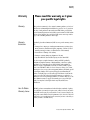
Important Notice:
In order to obtain warranty service on your Proteus 2000 unit, the serial number
sticker must be intact and you must have a sales receipt or other proof of
purchase. If there is no serial number sticker on the Proteus 2000, please contact
E-MU Systems at once.
This product is covered under one or more of the following U.S. patents:
4,404,529; 4,506,579; 4,699,038; 4,987,600; 5,013,105; 5,072,645;
5,111,727; 5,144,676; 5,170,367; 5,248,845; 5,303,309; 5,317,104;
5,342,990; 5,430,244 and foreign patents and/or pending patents. Proteus
2000 is a registered trademarks of E-MU Systems, Inc. All other trademarks
belong to their respective companies.
Proteus 2000 Operation Manual i
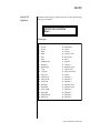
Table of Contents
Table of Contents
Introduction ............................................................................. 1
Product Description ............................................................................. 1
Overview ............................................................................................. 2
Important Safety Instructions .................................................. 3
Setup ...................................................................................... 13
Unpacking ......................................................................................... 13
Connection Instructions ..................................................................... 14
Basic Setup ...............................................................................................14
Studio Setup .............................................................................................15
Performance Setup ...................................................................................16
Power Up! ................................................................................................17
Instant Gratification ........................................................................... 18
Playing Demo Sequences ..........................................................................18
Auditioning Presets ...................................................................................18
Selecting and Quick Editing Presets ..........................................................19
Basic Operations .................................................................... 21
Front Panel ........................................................................................ 21
Volume Control ........................................................................................21
Master Button ..........................................................................................21
Edit Button ...............................................................................................21
Control Button .........................................................................................21
Audition Button ........................................................................................22
Left/Right Cursor Buttons .........................................................................22
Multimenu Button ....................................................................................22
Save/Copy Button ....................................................................................22
Home/Enter Button ..................................................................................23
Data Entry Control ....................................................................................23
Controller Knobs ......................................................................................23
Front Panel Controller Modes ............................................................ 23
Real-time Control .....................................................................................23
Quick Edit .................................................................................................24
Deep Edit Mode .......................................................................................25
ii E-MU Systems
Table of Contents
Main Screen ....................................................................................... 26
MIDI Channel Selection ............................................................................ 26
Preset Selection ........................................................................................ 26
Channel Volume ....................................................................................... 27
Channel Pan ............................................................................................. 28
Sound Navigator ................................................................................ 29
Preset Category ........................................................................................ 29
Instrument Category ................................................................................ 29
Multitimbral Operation ...................................................................... 30
Multimenu ..............................................................................31
Restoring Multisetups ............................................................................... 32
Multitimbral Sequencing.................................................................... 34
Master Menu ...........................................................................35
Defining Master Parameters ............................................................... 36
Transpose/Tune ........................................................................................ 36
Bend Range .............................................................................................. 36
Velocity Curve .......................................................................................... 37
Mix Output .............................................................................................. 38
Master Effects..................................................................................... 40
Effects Mode ............................................................................................ 40
Effects Multi Mode Control ....................................................................... 40
Master FXA Algorithm .............................................................................. 41
A Effect Types ....................................................................................... 41
FXA Parameters: Decay/HF Damping FxB -> FxA ...................................... 42
FXA Send Amounts ................................................................................... 42
Master FXB Algorithm .............................................................................. 42
B Effect Types ....................................................................................... 43
FXB Parameters: Feedback/LFO Rate Delay Time ...................................... 43
FXB Send Amounts ................................................................................... 43
MIDI Parameters ................................................................................ 44
MIDI Mode .............................................................................................. 44
MIDI SysEx ID ........................................................................................... 44
MIDI Enable ............................................................................................. 45
MIDI Program Change -> Preset ............................................................... 45
Receive Program Change ......................................................................... 46
Real-time Controller Assignment .............................................................. 46
MIDI Footswitch Assign ............................................................................ 47
Tempo Controller ..................................................................................... 48
Knob Preset Quick-Edit ............................................................................. 48
Knobs Deep Edit ....................................................................................... 49
Knobs/Riff MIDI Out ................................................................................. 49
Preset Edit All Layers Enable ...................................................................... 49
Front Panel Knob Calibration .................................................................... 50
MIDI SysEx Packet Delay ........................................................................... 51
Proteus 2000 Operation Manual iii
Table of Contents
Send MIDI System Exclusive Data .............................................................51
User Key Tuning .......................................................................................53
Output Format .........................................................................................53
Base Tempo ..............................................................................................54
Screen Viewing Angle ...............................................................................54
Programming Basics .............................................................. 55
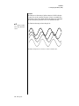
Modulation........................................................................................ 56
Modulation Sources ........................................................................... 57
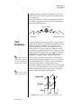
Random Sources .......................................................................................58
Modulation PatchCords ..................................................................... 58
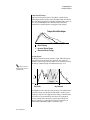
Envelope Generators .......................................................................... 59
Tempo-based Envelopes .......................................................................60
Envelope Repeat ...................................................................................60
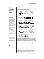
Low Frequency Oscillators (LFOs)....................................................... 61
Clock Modulation .............................................................................. 62
Modulation Destinations.................................................................... 64
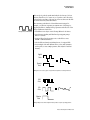
Modulation Processors ....................................................................... 65
Preset Modulation Processors............................................................. 67
Using the Modulation Processors ..............................................................69
More Examples .........................................................................................71
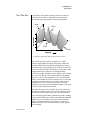
Dynamic Filters .................................................................................. 73
What is a Filter? ........................................................................................74
Parametric Filters ......................................................................................77
The Z-Plane Filter ......................................................................................78
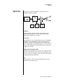
Signal Flow ........................................................................................ 79
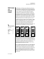
MIDI Channels and Real-time Controls............................................... 80
Bank Select Commands ............................................................................82
Stereo Mix Outputs ........................................................................... 83
Edit Menu ............................................................................... 85
Preset Name .............................................................................................86
Four Layer Architecture ...................................................................... 87
Selecting Layers ........................................................................................87
Defining Layer Parameters ................................................................. 88
Selecting an Instrument ............................................................................88
Sound Navigator ..................................................................................88
Defining Key Range ..................................................................................89
Defining the Velocity Crossfade Range ......................................................92
Defining the Real-time Crossfade Range ...................................................94
Transposing the Instrument ......................................................................97
iv E-MU Systems
Table of Contents
Tuning ..................................................................................................... 98
Background: Transpose vs. Coarse Tuning ............................................ 98
Amplifier .................................................................................................. 98
Volume Envelope ..................................................................................... 99
Selecting the Mode .............................................................................. 99
Defining the Volume Envelope ........................................................... 100
Chorusing the Layer ............................................................................... 101
Sound Start Offset and Delay ................................................................. 101
Non-Transpose Mode ............................................................................. 102
Solo Mode ............................................................................................. 102
Assign Group .......................................................................................... 103
Glide ...................................................................................................... 104
Z-Plane Filters ......................................................................................... 104
Proteus 2000 Filter Types ....................................................................... 108
Filter Parameters ................................................................................ 108
Filter Envelope ........................................................................................ 108
Envelope Repeat ................................................................................. 109
Defining the Filter Envelope ............................................................... 110
Auxiliary Envelope .................................................................................. 110
Low Frequency Oscillators (LFOs) ........................................................... 110
Shape ................................................................................................. 111
Sync ................................................................................................... 112
Rate ................................................................................................... 112
Delay ................................................................................................. 113
Variation ............................................................................................ 114
PatchCords ............................................................................................. 115
Modulator Polarity ............................................................................. 116
Pitch Bend Range ................................................................................... 118
Mix Output ............................................................................................ 118
Common Preset Parameters ............................................................. 119
Preset Effects ......................................................................................... 119
FXA Algorithm ........................................................................................ 121
A Effect Types ..................................................................................... 121
FXA Parameters ...................................................................................... 122
FXA Send Amounts ................................................................................. 122
FXB Algorithm ........................................................................................ 122
B Effect Types ..................................................................................... 122
FXB Parameters ...................................................................................... 123
FXB Send Amounts ................................................................................. 123
Preset Patchcords ................................................................................... 123
Initial Controller Amount ........................................................................ 125
Keyboard Tuning .................................................................................... 126
Preset Links ........................................................................................ 128
Preset Tempo Offset ............................................................................... 129
Audition Riff Selection ............................................................................ 129
Play Solo Layers ...................................................................................... 129
Proteus 2000 Operation Manual v
Table of Contents
Programming Tutorial ......................................................... 131
Editing Presets ................................................................................. 131
Changing the Instrument .......................................................................131
Changing the Tuning of an Instrument ...................................................132
Chorus ...................................................................................................133
Volume Envelope ....................................................................................133
Working with Filters ................................................................................135
Adding the Filter Envelope ..................................................................136
Changing Filter Types .........................................................................138
Envelope Repeat .................................................................................139
Practice Modulating ...............................................................................139
Troubleshooting .....................................................................................140
Linking Presets ................................................................................. 141
Using External Processing .......................................................................142
Effects ................................................................................... 143
Effects Overview .............................................................................. 143
The Effects Sends ....................................................................................143
Effect Types...................................................................................... 145
Effect Parameters ....................................................................................145
Decay .................................................................................................146
High Frequency Damping ..................................................................146
Feedback ............................................................................................146
LFO Rate ............................................................................................146
Delay ..................................................................................................146
Effects Programmed in the Preset..................................................... 147
Master Effects .................................................................................. 148
Effects Mode ...........................................................................................150
Flexible Effects Control ...........................................................................150
Using the Effects Channel Settings in Multi Mode ...............................152
Effect B Into Effect A ...............................................................................152
General Effect Descriptions .............................................................. 154
Reverb ....................................................................................................154
Chorus ...................................................................................................155
Doubling ................................................................................................155
Slapback .................................................................................................155
Stereo Flanger ........................................................................................155
Delay ......................................................................................................156
Stereo Delay ...........................................................................................156
Panning Delay ........................................................................................156
Dual Tap .................................................................................................156
Vibrato ...................................................................................................156
Distortion ...............................................................................................156
vi E-MU Systems
Table of Contents
Save/Copy Menu ..................................................................157
Saving a Preset ................................................................................. 157
Copying Information........................................................................ 158
Copy Preset ............................................................................................ 158
Copy Layer ............................................................................................. 158
Copy PatchCords ................................................................................... 159
Copy Preset PatchCords ......................................................................... 160
Copy Preset Bank ................................................................................... 160
Create Random Preset ............................................................................ 161
Copy User Bank to Flash ......................................................................... 162
Rename Flash SIMM ............................................................................... 163
Duplicate Flash ....................................................................................... 164
Appendix ...............................................................................165
Front Panel Knob Functions.............................................................. 165
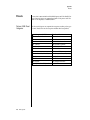
Presets ............................................................................................. 166
Proteus 2000 Preset Categories .............................................................. 166
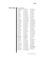
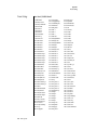
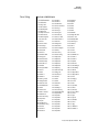
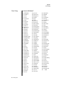
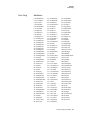
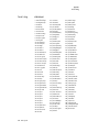
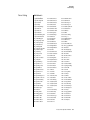
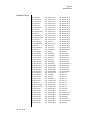
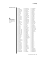
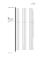
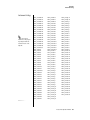
Preset Listing.................................................................................... 167
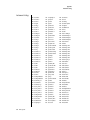
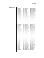
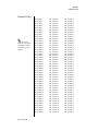
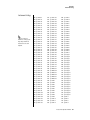
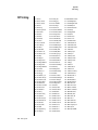
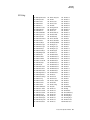
Instrument Listing ............................................................................ 175
Riff Listing ........................................................................................ 184
Velocity Curves................................................................................. 187
PatchCord Amount Chart................................................................. 189
MIDI ................................................................................................ 190
Received Channel Commands ................................................................ 191
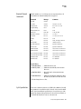
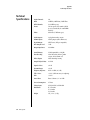
Technical Specifications.................................................................... 192
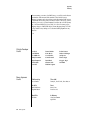
Warranty .......................................................................................... 193
Index .....................................................................................195
Proteus 2000 Operation Manual vii
Table of Contents
viii E-MU Systems
Introduction
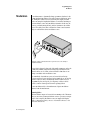
Congratulations on your purchase of the E-MU Proteus 2000 – the
composer’s dream machine. The power of Proteus 2000 begins with 128
voice polyphony, which means that 128 different instrument lines can be
played at once! With all these voices, 16 MIDI channels didn’t seem to be
quite enough, so we added another MIDI input jack to allow 32 MIDI
channel operation. As long as we were going for the gold, we decided to
add the ability to access 128MB of sound memory on user upgradable
SIMMs. And there’s much more as you will soon discover.
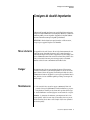
Product
Description
Proteus 2000 contains four user-upgradable sound SIMM sockets, allowing
you to mix and match sound sets according to your needs. New sounds can
be added as easily as plugging in a new 16MB or 32MB SIMM module and
up to 128MB of sounds can be added! Each sound set has been meticulously
crafted to be the best of its kind. Samples are matched across the keyboard,
perfectly looped, and rich in harmonic texture.
Proteus contains 512 user presets and can hold literally thousands of
factory presets. (ROM presets are automatically added when sound SIMMs are
installed. As an example, a 32 MB SIMM may contain up to 1024 ROM presets.)
Proteus 2000’s Sound Navigator is a major improvement to the main screen
that makes it easy to find the exact sound you want from the thousands
available. It’s powerful, yet simple to use.
Of course the real power of Proteus 2000 becomes apparent when you
synthesize your own sounds. The extremely flexible yet easy to use, 4-layer
synthesizer voices make it easy to build sounds of any kind. Layers can be
switched or crossfaded using key position, velocity, real-time controllers or
any modulation source. Proteus 2000 also contains 50 different types of
2nd to 6th order resonant & modeling filters which are used to shape and
modify the raw waveforms.
The 64 modulation sources include three multistage envelopes and two
LFOs per layer, as well as full MIDI control over virtually every parameter.
The digital patch bay, with 24 cords per layer, (and 12 more cords per
preset) lets you connect modulation sources to 64 destinations in any
imaginable way.
Proteus 2000 Operation Manual 1
Introduction
Overview
The patch bay contains a set of arithmetic modifiers, letting you create
complex synthesis models.
Four front panel real-time controllers give you control over 12 userselectable parameters. The real-time knobs can adjust multiple synthesizer
functions at once, allowing complex levels of control. For example, one
knob can simultaneously turn up filter cutoff, while detuning one sample,
and adjusting the release time of the volume envelope. Virtually every
synth parameter in the Proteus 2000 is controllable using the real-time
knobs or by any internal or external control source.
Six 20-bit analog outputs let you process separate sounds and integral effect
sends externally. Returns allow the addition of external effects units
without the need for a separate mixer.
Once you have created your preset, you can add richness to your sound
using Proteus 2000’s 24-bit stereo effects. You can choose a different effects
setup for each preset from over 60 algorithms. Proteus 2000’s effects section
is actually two separate effects processors with control over each wet/dry
mix level. Effects Processor “A” contains primarily ambiance algorithms
like reverb and delays, while effects processor “B” contains primarily
spectral algorithms such as chorus, flange, phase, distortion, and delay.
Effects can be linked to each preset or used globally to further enhance your
sound.
The S/PDIF digital stereo output lets you connect to other digital
equipment, such as digital mixers or external effects devices, keeping your
signal entirely in the digital domain.
Other features include multiple solo, voice assignment and performance
modes for expressive control, 12 user-definable alternate tunings, an
extremely easy to use interface and, of course, an extensive MIDI implementation.
Overview
This is the Operations Manual for setting up and playing Proteus 2000. The
first part of the manual describes how to unpack and setup the hardware.
The next chapters provide step-by-step instructions for the most common
and widely used features of Proteus 2000. This section also defines each of
the parameters (by menu) and provides information on how to use them.
The appendix provides technical information, product specifications and
the Index.
2 E-MU Systems
Important Safety Instructions
Use in countries other than the U.S.A. may require the use of a different
line cord or attachment plug, or both. Refer all servicing to qualified service
personnel. There are no user serviceable parts or adjustments inside the
unit. There are no user serviceable parts inside the power supply enclosure.
WARNING: To reduce the risk of fire or electric shock, do not expose this
product to rain or moisture.
Grounding
Instructions
Danger!
User
Maintenance
Instructions
This product must be grounded. If it should malfunction or break down,
grounding provides a path of least resistance for electric current, reducing
the risk of electric shock. This product is equipped with a cord having an
equipment-grounding conductor and a grounding plug. The plug must be
plugged into an appropriate outlet properly installed and grounded in
accordance with all local codes and ordinances.
Improper connection of the equipment’s grounding conductor can result in
the risk of electric shock. Check with a qualified electrician or service
personnel if you are in doubt as to whether the product is properly
grounded. Do not modify the plug provided with this product. If it will not
fit the outlet, have a proper outlet installed by a qualified technician.
1.
2.
The Proteus 2000 should be kept clean and dust free. Periodically wipe
the unit with a clean, dry, lint free cloth. Do not use solvents or
cleaners.
There are no user lubrication or adjustment requirements.
Caution -Servicing instructions are for use by qualified personnel only. To reduce
the risk of electric shock, do not perform any servicing other than that contained
in these operating instructions unless you are qualified to do so. Refer all servicing
to qualified service personnel.
Proteus 2000 Operation Manual 3
Important Safety Instructions
Overview
INSTRUCTIONS PERTAINING TO A RISK OF FIRE,
ELECTRIC SHOCK, OR INJURY TO PERSONS
READ THESE INSTRUCTIONS: When using electric products, basic precautions should always be adhered to, including the following:
1.
2.
This symbol is intended to
alert you to the presence of
important operating and
maintenance (servicing)
instructions in the literature
accompanying the unit.
3.
4.
5.
6.
7.
8.
9.
This symbol is intended to
alert you to the presence of
uninsulated dangerous
voltage within the product’s
enclosure that may be of
sufficient magnitude to
constitute a risk of electric
shock to persons.
10.
11.
12.
13.
14.
This symbol is intended to
alert you to use caution when
moving a cart/apparatus
combination to avoid injury.
4 E-MU Systems
15.
16.
Read all instructions before using Proteus 2000 .
Keep these instructions.
Heed all warnings.
Follow these instructions.
Do not use this apparatus near water.
Clean only with a dry cloth.
Install in accordance with E-MU’s instructions. Do not block any
openings. This apparatus should be situated so that its location or
position does not interfere with proper ventilation. The ventilation
should not be impeded by covering the ventilation openings with items
such as newspapers, tablecloths, curtains, etc.
Do not install near any heat sources such as radiators, heat registers,
stoves, or other apparatus (including amplifiers) which produce heat.
Do not defeat the safety purpose of the polarized or grounding-type
plug. A polarized plug has two blades with one wider than the other. A
grounding-type plug has two blades and a third grounding prong. The
wide blade or the grounding prong are provided for your safety. If the
provided plug does not fit into your outlet, consult an electrician for
replacement of the obsolete outlet.
Protect the power cord from being walked on or pinched, particularly at
plugs, convenience receptacles, and at the point where they exit from
the apparatus.
Use only attachments/accessories specified by E-MU Systems.
Use only with the cart, stand, tripod, bracket, or table specified by
E-MU or sold with the apparatus. When a cart is used, use caution when
moving the cart/apparatus combination to avoid injury from tip-over.
It is recommended that Proteus 2000 be rack mounted. You’ll need (4)
rack spaces to fit Proteus 2000 into your rack.
Unplug the Proteus 2000 apparatus from the power outlet during
lightning storms or when left unused for a long period of time.
Refer all servicing to qualified service personnel. Servicing is required
when the apparatus has been damaged in any way, such as power
supply cord or plug is damaged, liquid has been spilled or objects have
fallen into the apparatus, the apparatus has been exposed to rain or
moisture, the apparatus does not operate normally or has been
dropped.
No open flame sources, such as lit candles, should be placed on the
apparatus.
The apparatus is designed for use in moderate climates.
Important Safety Instructions
Overview
17.
18.
19.
20.
Radio and
Television
Interference
The apparatus shall not be exposed to dripping or splashing. No objects
filled with liquids, such as vases, shall be placed on the apparatus.
To reduce the risk of injury, close supervision is necessary when using
the apparatus near children.
The apparatus should be connected only to a power supply of the type
described in the operating instructions and marked on the product.
This product, in combination with an amplifier and headphones and
speakers, may be capable of producing sound levels that could cause
permanent hearing loss. Do not operate for a long period of time at a
high volume level or at a level that is uncomfortable. If you experience
any hearing loss or ringing in the ears, consult an audiologist.
The equipment described in this manual generates and uses radiofrequency energy. If it is not installed and used properly —that is, in strict
accordance with our instructions— it may cause interference with radio
and television reception.
This equipment has been tested and complies with the limits for a Class B
computing device in accordance with the specifications in Subpart J of Part
15 of the FCC rules. These rules are designed to provide reasonable
protection against such interference in a residential installation. However,
there is no guarantee that the interference will not occur in a particular
installation, especially if a “rabbit ear” TV antenna is used.
If Proteus 2000 does cause interference to radio or television reception, you
can try to correct the interference by using one or more of the following
measures:
•
•
•
•
Turn the television or radio antenna until the interference stops.
Move Proteus 2000 to one side or the other of the television or radio.
Move Proteus 2000 farther away from the television or radio.
Plug Proteus 2000 into an outlet on a different circuit than the television
or radio.
• Consider installing a rooftop antenna with a coaxial lead-in between the
antenna and television set.
Proteus 2000 Operation Manual 5
Wichtige Sicherheitsvorschriften
Overview
Wichtige Sicherheitsvorschriften
In Ländern außerhalb der U.S.A. können andere Kabel oder Stecker
notwendig werden. Überlassen Sie die Wartung qualifiziertem Fachpersonal. Im Geräteinnern befinden sich keine Bauteile oder Steuerungen, die
vom Anwender gewartet werden können. Das Gleiche gilt für das
Netzteilgehäuse.
VORSICHT: Um die Gefahr eines Brandes oder Stromschlags zu verringern,
sollten Sie das Gerät weder Regen noch Feuchtigkeit aussetzen.
Erdungsinstruktionen
Gefahr!
Wartungsinstruktionen
für Anwender
Das Gerät muss geerdet sein. Bei einem Defekt oder Ausfall bietet die
Erdung dem elektrischen Strom den Weg des geringsten Widerstandes und
reduziert das Risiko eines Stromschlages. Dieses Gerät ist mit einem
geerdeten Leiter und Stecker ausgerüstet. Der Stecker muss in eine passende,
einwandfrei montierte und geerdete Steckdose in Übereinstimmung mit
den örtlichen Vorschriften eingeführt werden.
Unvorschriftsmäßiger Anschluss des Gerätes kann zum Risiko eines
elektrischen Schlages führen. Im Zweifel über die ordnungsgemäße Erdung
sollte ein qualifizierter Elektriker oder eine Serviece-Stelle hinzugezogen
werden. Ändern Sie den mitgelieferten Stecker nicht. Falls er nicht in die
Steckdose passt, sollte die Installation einer neuen Steckdose nur durch
einen qualifizierten Techniker erfolgen.
1.
2.
Der sollte sauber und staubfrei gehalten werden. Das Gerät mit einem
sauberen und säurefreien Tuch periodisch abreiben. Keine Lösungsoder Reinigungsmittel anwenden.
Schmieren und Justieren sind nicht notwendig.
Vorsicht: Diese Gebrauchsanweisungen sind nur für qualifizierte Techniker
bestimmt. Um die Gefahr eines elektrischen Schlages zu vermeiden, sollten Sie
keine Arbeiten vornehmen, die nicht in diesen Instruktionen beschrieben sind.
Wenden Sie sich bei weiteren Servicefragen nur an eine qualifizierte Servicestelle.
6 E-MU Systems
Wichtige Sicherheitsvorschriften
Overview
INSTRUKTIONEN ZUM BRANDRISIKO, STROMSCHLAG ODER PERSONENSCHADEN
BITTE LESEN: Beim Einsatz elektrischer Geräte sollten folgende Vorsichtsmaßregeln stets beachtet werden:
1.
2.
3.
Dieses Symbol weist Sie auf
wichtige Bedienungs- und
Wartungsanleitungen in den
beiliegenden Drucksachen
hin.
4.
5.
6.
7.
8.
9.
10.
11.
Diese Symbol warnt Sie vor
nicht-isolierten gefährlichen
Spannungen im
Gehäuseinnern. Diese
können so hoch sein, dass
die Gefahr eines Stromschlags besteht..
12.
13.
14.
15.
16.
Lesen Sie vor dem Einschalten des Proteus 2000 alle Instruktionen.
Zur Vermeidung von Verletzungsrisiken müssen Kinder bei eingeschaltetem Proteus 2000 sorgfältig überwacht werden.
Den Proteus 2000 nicht in der Nähe von Wasser in Betrieb nehmen – z.
B. in der Nähe von Badewannen, Waschschüsseln, auf nassen Gestellen
oder am Swimmingpool.
Den Proteus 2000 keiner tröpfelnden oder spritzenden Feuchtigkeit
aussetzen. Keine mit Flüssigkeit gefüllten Objekte, wie Vasen, auf das
Gerät stellen.
Den Proteus 2000 stets so aufstellen, dass seine Belüftung nicht beeinträchtigt wird.
Den Proteus 2000 nicht in der Nähe von Hitzequellen aufstellen, wie
Heizkörper, offenem Feuer, Öfen oder von Backöfen.
Keine offenen Feuerquellen, wie Kerzen, auf dem Proteus 2000
abstellen.
Der Proteus 2000 ist nicht für den Einsatz in extremen
Klimaverhältnissen konzipiert.
Den Proteus 2000 ausschließlich mit einem Netzgerät gemäß Bedienungsanleitung und Gerätemarkierung verwenden.
Achten Sie darauf, dass keine Objekte oder Flüssigkeiten durch
Öffnungen ins Proteus 2000 Gehäuse gelangen.
Der Proteus 2000 ist mit einem polarisierten Kabelstecker (mit zwei
flachen Polen und einem Erdungsstift) ausgerüstet. Das geschieht zu
Ihrer Sicherheit. Können Sie den Stecker nicht in die Steckdose
einführen, ändern Sie nicht den Stecker ab, sondern wenden Sie sich an
einen Elektriker, um die veraltete Steckdose ersetzen zu lassen.
Verlegen Sie das Stromkabel so, dass niemand darüber laufen oder
stolpern und es nicht durch schwere Gegenstände geknickt werden
kann. Achten Sie besonders auf Netzstecker, Mehrfachsteckdosen und
den Kabelanschluss am Gerät.
Das Netzkabel bei Gewittern oder längerem Nichtgebrauch aus der
Steckdose ziehen.
Dieses Gerät kann bei Verwendung von Kopfhörern und Verstärkern
hohe Lautstärkepegel erzeugen, welche zu bleibenden Gehörschäden
führen. Arbeiten Sie nicht während längerer Zeit mit voller Lautstärke
oder hohem Pegel. Stellen Sie Gehörverlust oder Klingeln in den Ohren
fest, wenden Sie sich an einen Ohrenarzt.
Verwenden Sie nur die von E-MU Systems empfohlenen Befestigungen
und Zubehörteile.
Überlassen Sie die Wartung qualifiziertem Fachpersonal. Das Gerät soll
durch qualifizierte Fachkräfte gewartet werden, wenn:
Proteus 2000 Operation Manual 7
Wichtige Sicherheitsvorschriften
Overview
A.
B.
C.
D.
E.
das Netzkabel beschädigt wurde oder
Gegenstände oder Flüssigkeit in das Gerät gelangten,
das Gerät Regen ausgesetzt war oder
das Gerät stürzte oder sein Gehäuse beschädigt wurde
das Gerät nicht normal oder einwandfrei arbeitet oder Betriebsstörungen auftreten
Diese Instruktionen aufbewahren
Alle Warnungen beachten
Alle Instruktionen befolgen
Radio und TVInterferenzen
Das in diesem Handbuch beschriebene Equipment verwendet und erzeugt
Frequenzen im Radio/Fernsehbereich. Wird das Gerät nicht entsprechend
den hier beschriebenen Regeln installiert, können Störungen im Rundfunkund Fernsehempfang entstehen.
Das Gerät wurde getestet und entspricht den Regeln für Class B Computer
entsprechend den Spezifikationen in Subpart J von Part 15 der FCC Bestimmungen. Diese sollten angemessenen Schutz vor solchen Interferenzen in
Wohngebieten liefern. Es kann aber nicht garantiert werden, dass diese
Interferenzen bei bestimmten Installationen nicht doch auftreten –
besonders bei Verwendung von bestimmten TV-Zimmerantennen. Sollte
der Proteus 2000 den Radio- oder TV-Empfang stören, versuchen Sie mit
folgenden Maßnahmen, die Ursache zu beheben.
• Bewegen Sie den Fernseher oder die Antenne, bis die Störungen verschwinden.
• Stellen Sie den Proteus 2000 auf die jeweils andere Seite des TVs oder
Radios.
• Stellen Sie den Proteus 2000 weiter entfernt vom Radio oder TV auf.
• Verwenden Sie einen anderen Stromkreis für den Proteus 2000.
• Installieren Sie eine Dachantenne mit einer koaxialen Antenneneinführung zwischen Antenne und TV-Gerät.
Urheberrechts- Informationen
8 E-MU Systems
Die Firmenpolitik von E-MU / ENSONIQ gestattet allen Anwendern freie, vollständige und
uneingeschränkte Nutzung aller Presets, Beats, Riffs, Patterns und Audition-Dateien, die in
unseren Produkten enthalten sind. Wir können Ihnen allerdings nicht erlauben, die
Demo-Dateien erneut zu verwenden, zu modifizieren, darauf aufzubauen oder diese zu
verkaufen/vertreiben. Meistens sind diese Kompositionen von den jeweiligen Autoren
urheberrechtlich geschützt und an E-MU / ENSONIQ nur zur Produktdemonstration lizensiert. Setzen Sie sich bei weiteren Fragen bitte mit E-MU / ENSONIQ in Verbindung.
Consignes de sécurité importantes
Overview
Consignes de sécurité importantes
L’utilisation de l’appareil dans d’autres pays que les États-Unis peut nécessiter
l’usage d’un cordon d’alimentation et/ou d’une prise différent(s). Consultez un
technicien qualifié pour toute réparation. L’appareil et le dispositif d’alimentation ne contiennent aucune pièce réparable par l’utilisateur.
ATTENTION : Afin de réduire les risques d’incendie ou d’électrocution,
n’exposez pas cet appareil à la pluie ou à l’humidité.
Mise à la terre
Danger
Maintenance
Cet appareil doit être relié à la terre. En cas de dysfonctionnement, la terre
fournit un passage de moindre résistance pour le courant électrique et
réduit ainsi les risques d’électrocution. L’appareil Proteus 2000 équipé d’un
cordon d’alimentation muni d’un conducteur et d’une fiche polarisés. Cette
fiche doit être insérée dans une prise secteur appropriée correctement
installée et reliée à la terre conformément aux normes locales.
Une mauvaise mise à la terre peut entraîner des risques d’électrocution.
Consultez un électricien ou un technicien qualifié si vous avez des doutes
quant à la mise à la terre de l’appareil. Ne modifiez pas la fiche du cordon
d’alimentation fourni avec l’appareil. Si vous ne pouvez pas l’insérer dans la
prise, adressez-vous à un technicien qualifié pour faire poser une prise du
modèle adapté.
1.
2.
Le Proteus 2000 doit toujours être propre et maintenu à l’abri de la
poussière. Nettoyez-le régulièrement à l’aide d’un chiffon sec, propre et
non-pelucheux. N’utilisez pas de solvants ni de produits de nettoyage.
Aucune lubrification et aucun réglage ne sont nécessaires de votre part.
Attention : Les instructions de maintenance sont uniquement destinées à un
personnel qualifié. Afin d’éviter tout risque d’électrocution, n’intervenez pas audelà des instructions décrites dans ce mode d’emploi. Confiez toute réparation à
un technicien qualifié.
Proteus 2000 Operation Manual 9
Consignes de sécurité importantes
Overview
CONSIGNES RELATIVES AUX RISQUES D’INCENDIE,
D’ÉLECTROCUTION OU DE BLESSURES CORPORELLES
LISEZ CES CONSIGNES : Lorsque vous utilisez des appareils électriques,
certaines précautions élémentaires doivent toujours être respectées. En
voici quelques-unes:
1.
2.
3.
Ce symbole attire l’attention
de l’utilisateur sur la présence
d’instructions d’utilisation et
de maintenance importantes
dans le mode d’emploi fourni
avec l’appareil
4.
5.
6.
7.
8.
9.
10.
11.
Ce symbole attire l’attention
de l’utilisateur sur la présence
de tensions élevées dans
l’appareil, susceptibles de
constituer un risque
d’électrocution.
12.
13.
14.
15.
10 E-MU Systems
Lisez toutes les instructions avant d’utiliser le Proteus 2000.
Afin de limiter les risques de blessures, une surveillance particulière est
nécessaire lorsque vous utilisez le Proteus 2000 en présence d’enfants.
N’utilisez pas le Proteus 2000 près de l’eau (près d’une baignoire, d’un
lavabo, d’un évier, dans un sous-sol humide, sur une surface mouillée
ou près d’une piscine, par exemple).
N’exposez pas l’appareil aux éclaboussures. Ne posez aucun récipient
contenant de l’eau (vases, par exemple) sur le Proteus 2000.
Le Proteus 2000 doit être placé de sorte que sa position ou son emplacement ne gênent pas sa ventilation.
Ne placez pas le Proteus 2000 à proximité de sources de chaleur
(radiateur, cheminée ou four, par exemple).
Ne posez aucune source incandescente (bougies, par exemple) sur le
Proteus 2000.
Le Proteus 2000 ne doit pas être utilisé dans des environnements à
températures extrêmes.
Le Proteus 2000 doit uniquement être connecté à une alimentation du
type décrit dans le mode d’emploi et sérigraphié sur l’appareil.
Veillez à ce qu’aucun corps ou liquide étranger ne s’introduise dans le
Proteus 2000.
Le Proteus 2000 est équipé d’une fiche polarisée (une broche plus large
que l’autre). Ce type de fiche constitue une mesure de sécurité. Si vous
ne pouvez pas insérer la fiche dans la prise, contactez un électricien
pour faire poser une prise du modèle adapté.
Faites circuler le cordon d’alimentation de sorte qu’il ne puisse pas être
écrasé ou pincé par d’autres objets. Soyez particulièrement vigilant au
niveau des connexions à l’appareil ou aux prises secteur.
En cas d’orage ou si l’appareil doit rester inutilisé pendant une période
prolongée, débranchez le cordon d’alimentation du Proteus 2000 de la
prise secteur.
Cet appareil, associé à un amplificateur et à un casque ou des enceintes,
est capable de délivrer des niveaux sonores susceptibles d’entraîner des
pertes auditives irrémédiables. Ne l’utilisez pas de manière prolongée à
un niveau élevé ou inconfortable. En cas de troubles de l’audition ou de
bourdonnement d’oreilles, consultez un spécialiste.
Utilisez uniquement les accessoires préconisés par E-MU Systems.
Consignes de sécurité importantes
Overview
16.
Confiez l’appareil à un technicien qualifié dans chacun des cas
suivants :
A. Le cordon d’alimentation ou la prise a été endommagé.
B. Des corps étrangers ou du liquide se sont introduits dans
l’appareil.
C. Le Proteus 2000 a été exposé à la pluie ou à l’humidité.
D. Le Proteus 2000 est tombé ou a été endommagé d’une manière
ou d’une autre.
E. Le Proteus 2000 ne fonctionne pas normalement ou présente une
baisse sensible de ses performances.
Conservez ces instructions.
Respectez tous les avertissements
Suivez toutes les instructions
Interférences
radio et TV
L’appareil décrit dans ce mode d’emploi génère et utilise des fréquences
radio/TV. S’il n’est pas installé conformément aux instructions décrites, il
peut interférer avec la réception TV ou radio.
Cet appareil a été testé et est conforme aux normes de Classe B selon les
spécifications du paragraphe J de la section 15 des dispositions FCC. Ces
dispositions sont conçues pour protéger les installations résidentielles
contre ce type d’interférences. Toutefois, l’absence d’interférences ne saurait
être totalement garantie avec certains types d’installations, en particulier si
vous utilisez certaines antennes TV internes.
Si le Proteus 2000 interfère avec la réception TV ou radio, vous pouvez
essayer les mesures suivantes:
• Réorientez l’antenne ou le poste de télévision jusqu’à ce que les interférences disparaissent.
• Placez le Proteus 2000 de l’autre côté du poste de télévision ou de la
radio.
• Eloignez le Proteus 2000 du poste de télévision ou de la radio.
• Branchez le Proteus 2000 sur une prise différente de celle de la télévision
ou de la radio.
• Installez une antenne sur le toit par le biais d’une connexion coaxiale
entre l’antenne et le poste de télévision.
Proteus 2000 Operation Manual 11
Consignes de sécurité importantes
Overview
12 E-MU Systems
Setup
This section thoroughly describes how to set up your new Proteus 2000 for
use. Setup includes unpacking instructions and how to connect the Proteus
2000 cables.
Unpacking
Carefully remove Proteus 2000 from the packaging material. Take care to
save the packing materials in case you need to transport the unit. Check to
make sure all components are included and in good condition. If there are
missing or damaged components, contact E-MU Systems immediately for
replacement or repair.
The Proteus 2000 box should include the following components:
•
•
•
•
Proteus 2000 unit
Power cable
Rack mounting ears
This Operations Manual
Proteus 2000 Operation Manual 13
Setup
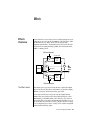
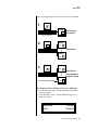
Connection Instructions
Connection
Instructions
MIDI Controller
(MIDI Keyboard, Sequencer, etc.)
REAL
TIME
The Headphone
Output is located
on the Front Panel
CONTROLLERS
ASSIGNABLE
KEYS
PRESET
LEVEL
EXIT
ENTER
SAMPLE
PAGE
SEQUENCER
PRESET SELECT
1
2
3
4
5
6
RETURN
7
8
9
0
.
EMULATOR
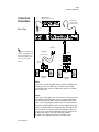
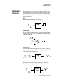
Basic Setup
Control
Pedal
MIDI Out
~
B
A
To
Main Outs
If Proteus 2000 does not
seem to be responding correctly,
make sure that both Proteus
2000 and your MIDI controller
are set to the same MIDI
channel.
THRU
SCOTTS VALLEY CA. U.S.A.
Main Outs to Mixer In
IN
Male RCA plug
to
Male Phono Plug
Mixer
Aux. or
Tape In
Amp
Speakers
Home Stereo
System
Home Studio
System
MIDI In
Proteus 2000 is controlled by MIDI messages received at the MIDI A jack.
Normally you will connect MIDI Out of a controller such as a MIDI
keyboard, MIDI wind controller or MIDI guitar controller to the MIDI A
jack of Proteus 2000.
Outputs
Proteus 2000 is a high quality, stereo audio device. In order to reproduce its
wide dynamic range and frequency response, use a high quality amplification and speaker system such as a keyboard amplifier or home stereo
system. A stereo setup is highly desirable because of the added realism of
stereophonic sound. Headphones can be used if an amplifier and speaker
system is not available. Plug stereo headphones into the headphone jack
located on the left side of the front panel. The Right Main output jack
serves as a mono output when the Left Main plug is not plugged in. The
Left Main output jack is a stereo jack carrying both channels.
The S/PDIF output duplicates the function of the main output.
14 E-MU Systems
Setup
Connection Instructions
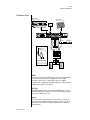
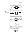
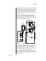
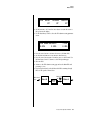
Studio Setup
MIDI Controller
(MIDI Keyboard, Sequencer, etc.)
REAL
TIME
Computer
CONTROLLERS
ASSIGNABLE
KEYS
PRESET
LEVEL
EXIT
ENTER
SAMPLE
PAGE
SEQUENCER
PRESET SELECT
1
2
3
4
5
6
RETURN
7
8
9
0
.
Computer
EMULATOR
Additional
MIDI
Devices
MIDI Out
MIDI In
In
MIDI
Interface
Out
In
Out
Out
“A” MIDI
channels
1-16
~
“B” MIDI
channels
1-16
B
A
IN
THRU
SCOTTS VALLEY CA. U.S.A.
Mixer
Amp
MIDI In
In this setup, Proteus 2000 is controlled by MIDI messages, received at both
MIDI A and MIDI B inputs, which are routed by the MIDI interface. Each
MIDI input handles 16 MIDI channels for a total of 32 channels. The MIDI
interfaces allow any MIDI controller, such as a MIDI keyboard or a
computer, to control the module.
MIDI Out
The MIDI Out jack transmits program data to a computer or other device.
Outputs
Three sets of programmable stereo outputs (Main, Sub 1, and Sub 2) are
provided. The internal effects are available only on the Main outputs.
Specific presets (or MIDI channels) can be routed to one of these stereo
pairs in order to be processed further or mixed separately. The S/PDIF
output duplicates the function of the main output.
Proteus 2000 Operation Manual 15
Setup
Connection Instructions
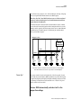
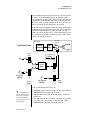
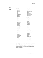
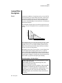
Performance Setup
MIDI Controller
MIDI Controller
(MIDI Keyboard, Sequencer)
REAL
TIME
(MIDI Percussion Controller)
CONTROLLERS
ASSIGNABLE
KEYS
PRESET
LEVEL
EXIT
ENTER
SAMPLE
PAGE
SEQUENCER
PRESET SELECT
1
2
3
4
5
6
RETURN
7
8
9
0
.
EMULATOR
Additional
MIDI
Device
MIDI In
MIDI Out
~
MIDI Out
B
A
Effect Device
Main Outs to Mixer In
Send/Return
Send
IN
THRU
SCOTTS VALLEY CA. U.S.A.
S/PDIF In
Volume
Mix
Digital Effect
Data Entry
Control 1
Control 2
Control 3
Control 4
Effect: Swirling Reverb
Parameter Edit
Analog Out
Sub Output
Return
(To Main Output)
Tip
To Effect
Ring
From Effect
SEND/RETURN CABLE
Signal is sent out on tip of plug and
returned to main outputs via ring of plug.
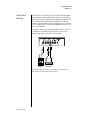
MIDI In
Proteus 2000 is controlled by MIDI messages received at either MIDI input.
In a live performance situation, you might want to use two MIDI
controllers as shown above. Connect MIDI outputs of your MIDI
controllers such as a MIDI keyboard, MIDI drum pads or a MIDI sequencer
to MIDI Inputs A and B of Proteus 2000.
MIDI Thru
The MIDI Thru jack is used to connect additional MIDI devices onto the
MIDI chain. MIDI Thru transmits an exact copy of the messages received at
the respective MIDI In jack (A or B).
Outputs
The Sub 1 and Sub 2 output jacks are stereo jacks. The tip of each jack
(accessed when a standard phone plug is inserted) connects to the left or
right output of that group. The S/PDIF output duplicates the function of
the main output.
16 E-MU Systems
Setup
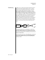
Connection Instructions
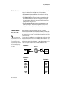
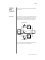
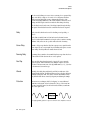
If you insert a stereo plug into one of the Sub Outputs, the ring of the plug
serves as a signal Return which sums into the Main outputs.
Therefore, the Sub 1 and Sub 2 jacks can serve as effect sends and
returns in order to further process selected instruments and then
return them to the main mix.
You can use the Sub 1 and Sub 2 jacks as send/returns in order to further
process selected Proteus 2000 presets without using the effects bus on the
mixing board. In a pinch, the effect returns can be used to sum additional
instruments into the main outputs. It’s like having an extra line mixer
when you need more inputs!
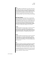
Output Section
Effects
Processors
L Bus
R Bus
Tip
Tip
Tip
Tip
Ring
Ring
Ring
Ring
R
L
R
L
SUB 2
SUB 1
R
L
MAINS
You can use the Sub 1 and Sub 2 jacks as effect returns to the Main Outputs.
Note that the Effects Processors are only routed to the Main Outputs.
Power Up!
The power switch is located on the right side of the front panel. You can
turn on the Proteus 2000 and its MIDI controller in any order. When power
is applied the liquid crystal display will light, indicating that Proteus 2000
is operating. You may have noticed that there is no 110/220 Volt power
selector switch on Proteus 2000.
Proteus 2000 automatically switches itself to the
proper line voltage.
Proteus 2000 Operation Manual 17
Setup
Instant Gratification
Instant
Gratification
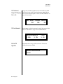
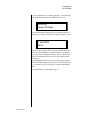
Playing Demo
Sequences
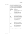
This section presents step-by-step instructions for the most fundamental
operations to get you up and making sounds quickly.
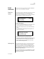
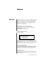
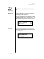
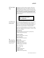
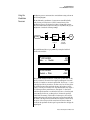
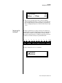
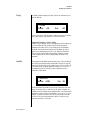
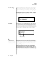
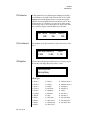
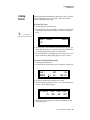
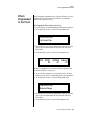
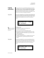
Proteus 2000 has several factory demonstration sequences that let you hear
what this incredible machine can do. The actual number of demo
sequences depends on which ROM sounds sets are installed. You can play
these demo sequences by accessing the Demo Sequence page.
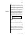
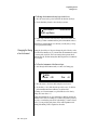
DEMO SEQUENCES
P2K GonzoPop
1.
2.
3.
CMPSR
To Play a Demo Sequence
Press and hold the Master and Edit buttons at the same time to enter
the Demo Sequence page. The screen shown above appears.
Select a sequence using the data entry control. The Enter LED will be
flashing.
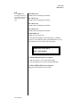
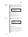
Press the Enter button to begin playing the selected sequence. The
screen shown below appears.
PLAYING: P2K GonzoPop
Press ENTER to stop
4.
Press the Enter button again to stop playing the sequence.
5.
When a demo sequence plays to the end, the next demo will automatically begin playing. The screen will display the new demo name.
With the sequence stopped, press either the Master, Edit or Multi
button to Exit the demo sequence mode.
6.
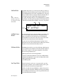
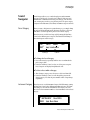
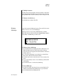
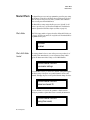
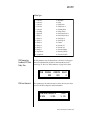
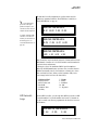
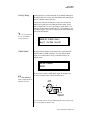
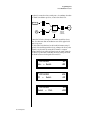
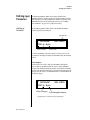
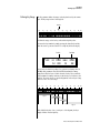
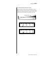
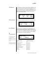
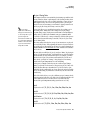
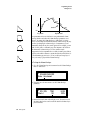
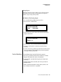
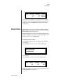
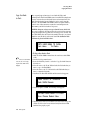
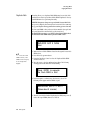
Auditioning Presets
The front panel audition button allows you to hear any preset in Proteus
2000 without even hooking up a MIDI keyboard! When the Audition
button is pressed, the LED next to the button will illuminate and a short
“Riff” (programmed as part of the preset) will play. The Riff is latched on
and plays continuously until the button is pressed again. Presets can be
changed while Audition is latched on.
The top line of the display changes to show the MIDI Bank Select controller
values needed to select the preset being auditioned. This is an extremely
handy feature when sequencing.
18 E-MU Systems
Setup
Instant Gratification
BankSel 0:00
32:2
2
058
syn: Big Planet
1.
2.
3.
4.
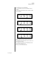
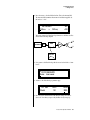
Selecting and Quick
Editing Presets
User
To Audition a Preset
Select a preset by turning the data entry control while the cursor is
anywhere on the lower line. The preset number field (shown above) is
the normal position of the cursor and pressing the Enter button will
return the cursor to this position.
Press the Audition button on the front panel. The Audition LED will
illuminate and a short riff will play the selected preset.
Continue to select and audition presets.
Press the Audition button again to turn Audition mode off. The LED
will extinguish.
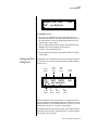
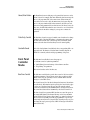
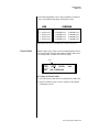
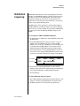
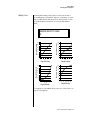
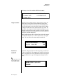
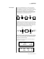
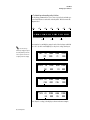
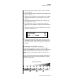
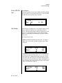
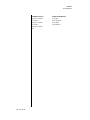
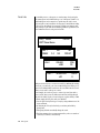
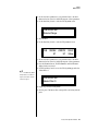
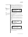
The first thing you’ll do with the Proteus 2000 is select and play the factory
provided presets. Proteus 2000 comes standard with 12 banks containing
128 presets each.
Channel
Number
C01
0000
Preset
Number
Initial
Volume
Setting
Initial
Pan
Setting
Preset
Location
Vol127
Pan01R
bas: Interference
Bank
Number
Preset
Category
User
Preset
Name
The first four banks are User locations that can be overwritten and used to
store your own presets. The presets that come stored in the User presets are
duplicated in banks 4-7 of the “CMPSR” ROM bank, so feel free to overwrite
them with your own presets. You won’t be losing anything.
The ROM Card identifier is shown in the top right of the display. The preset
is identified in the bottom line of the main screen (the screen that appears
when you first power up the unit).
Proteus 2000 Operation Manual 19
Setup
Instant Gratification
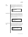
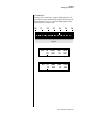
Each bank of 128 presets is identified by a superscripted Bank Number to the
right of the preset number. The bank numbers reset to 0 at the start of each
ROM card you have installed. So with the composer ROM installed, the
User banks will go from 0-3, then start over from 0-7 for the CMPSR banks.
To the right of the preset number and bank is the preset Category name
followed by the Preset Name.
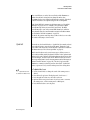
1.
O
You can select presets
from the Preset Number, Bank
Number, Preset Category or
Preset Name fields.
2.
3.
4.
To Change the Preset
Place the cursor under the first character in the Preset Number field.
This is the “Home” position which is selected instantly when you press
the Home/Enter button. Pressing either of the two cursor buttons
repeatedly also gets you there.
Turn the Data Entry Control knob on the front panel to select a new
preset number. If you turn the knob slowly, the presets advance one
number for each “click” of the knob. If you spin the knob quickly, the
numbers advance much faster (more than one number per click).
Play the keyboard (or press the Audition button) and listen to the
sounds made by your Proteus 2000!
TURN THE FOUR KNOBS on the front panel and note how they
change the sound of each preset! The button to the left of the knobs
changes the knob’s function. Don’t worry about ruining the sound, the
values are automatically reset as soon as you select a new preset.
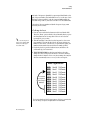
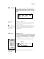
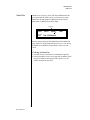
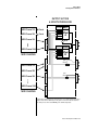
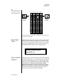
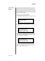
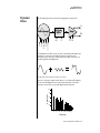
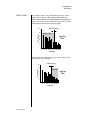
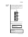
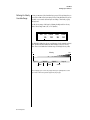
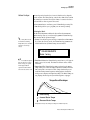
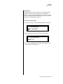
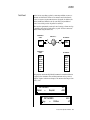
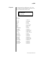
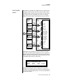
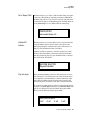
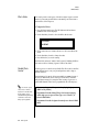
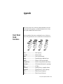
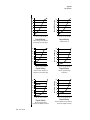
Bank Organization
The User Banks
are duplicated
in the Composer
ROM bank.
}
USER
USER
USER
USER
Bank 0
Bank 1
Bank 2
Bank 3
128 Presets
128 Presets
128 Presets
128 Presets
CMPSR
CMPSR
CMPSR
CMPSR
CMPSR
CMPSR
CMPSR
CMPSR
Bank 0
Bank 1
Bank 2
Bank 3
Bank 4
Bank 5
Bank 6
Bank 7
128 Presets
128 Presets
128 Presets
128 Presets
128 Presets
128 Presets
128 Presets
128 Presets
The four User Banks can hold 512 custom presets. Feel free to overwrite these
since the factory user presets are duplicated in nonvolatile ROM.
20 E-MU Systems
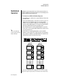
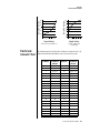
Basic Operations
Control
Button
A-D
E-H
I-L
Volume
Control
TONE
ATTACK
DYNAMIC 1
PRESENCE
DECAY/RLS
DYNAMIC 2
Edit
Menu
Master
Menu
SHAPE
MOVEMENT
FX A
IMAGE
RATE
FX B
MASTER
Cursor
Controls
Power
Switch
EDIT
CO 1 A Vo l 1 27 Pan0 1 R CMPSR
022 3 s t r : Ba r oqueQua r t e t
VOLUME
A/E
B/F
C/G
POWER
D/H
AUDITION
MULTI
SAVE/COPY
HOME/ENTER
MIDI
Display
Headphone
Jack
Realtime
Control Knobs
Front Panel
Audition
Button
Multimode
Button
Save/
Copy
Home/
Enter
Data
Entry
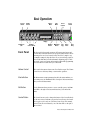
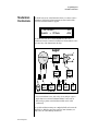
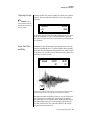
The Proteus 2000 front panel contains an LCD screen, nine buttons and
four real-time controllers. Functions are grouped logically and the controls
are arranged for ease of use. Precisely because Proteus is so simple to use,
you might be tempted to skip this section. If you just can’t help yourself, at
least read the Real-time Controller information beginning page 23. There
are several “power user” features in the interface which make programming
even easier and we wouldn’t want you to miss them.
Volume Control
This control is the master volume control for all audio outputs. The Volume
Control does not affect any editing or user interface operations.
Master Button
The Master menu contains parameters that affect the entire machine, not
just certain presets. An illuminated LED to the right of the button indicates
that you are in the Master menu.
Edit Button
Use the Edit menu when you want to create or modify a preset. An illuminated LED to the right of the button indicates that you are in the Edit
menu.
Control Button
The Control button is used to change the function of the Controller knobs
(see the next section). Each time you press the Control button, the Control
Mode toggles to select only one of the three Control Rows. The currently
selected Control Row is indicated by one of the three LEDs to the right of
the row’s label.
Proteus 2000 Operation Manual 21
Basic Operations
Front Panel
Audition Button
O
See “Bank Select
Commands“ on page 82 for
more information on selecting
banks via MIDI.
The Audition button allows you to hear any preset without hooking up a
MIDI keyboard. When the Audition button is pressed, the LED next to the
button will illuminate and a short “Riff” (programmed as part of the preset)
will play. The Riff is latched on and plays continuously until the button is
pressed again. Presets can be changed while Audition is latched on.
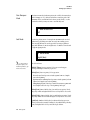
The top line of the display changes to show the MIDI Bank Select controller
values needed to select the preset being auditioned. This handy feature lets
you know the exact Bank and Preset number to enter into your sequencer.
MSB
Preset #
Left/Right Cursor
Buttons
LSB
BankSel 0:004 32:3
0023 pad: RiffTrippin’
CMPSR
These buttons move the cursor to the next parameter on the display. (The
cursor is a little flashing line underneath one of the parameters in the
display.) Press either cursor button until the cursor is underneath the
desired parameter. The cursor buttons have an auto-repeat feature which
advances the cursor when the button is held continuously.
The cursor can be moved bidirectionally using the Data Entry Control
while either cursor select button is held down (for example, press and hold
the right cursor button and turn the Data Entry Control).
Multimenu Button
The Multimenu button allows you to select a Multi-setup. A Multi-setup is a
group of parameters that you might associate with a particular sequence or
song. It is like a “snapshot” of the current configuration of the module.
There are 128 setups numbered 0-127.
A Multisetup includes all of the following parameters:
• The Preset/Volume/Pan assignments for each of the 32 MIDI channels.
• All Master menu parameters, except for the User Tuning Tables and the
MIDI program change->preset map.
• The Multisetup name.
Save/Copy Button
The Save/Copy button is used to save or copy presets and to copy data.
Selected groups of parameters, such as PatchCord settings, can be copied
between Presets and/or between Layers using this menu.
The LED to the right of the button illuminates to indicate that you are in
the Save/Copy menu. The LED also illuminates when any preset parameter
has been changed in the Edit menu (or if the front panel knobs have been
moved with Quick-Edit mode enabled).
22 E-MU Systems
Basic Operations
Front Panel Controller Modes
Home/Enter Button
The Home/Enter button is dual purpose. In general, this button acts as the
“Home” button. For example, when in an Edit menu, this button snaps the
cursor to the page name field of the current screen. When viewing the
Preset Select screen (we also call it the main screen), this button snaps the
cursor to the preset number field. In these instances, the LED is not used.
Some screens and parameter fields use this button as the “Enter” button. In
these cases, the LED blinks when the cursor is moved to one of these fields
indicating that the module is waiting for your response to initiate the
operation.
Data Entry Control
The Data Entry Control is a stepped, variable control switch used to change
parameter values. The wheel increments or decrements the current value
one unit with each click. This control incorporates acceleration, which
advances the value faster if the Data Entry Control is turned quickly.
Controller Knobs
Each of the four Real-time Controller knobs has a corresponding LED to its
upper right side. The function of the Real-time Controllers depends on
which row is currently selected and the programming of the preset.
Front Panel
Controller
Modes
The Real-time Controller Knobs serve three purposes:
1.
2.
3.
Real-time control of synthesizer parameters
“Quick Editing” the initial settings of the real-time controllers
“Deep Editing” the parameters
This section describes each of the three uses.
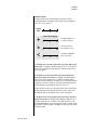
Real-time Control
The Real-time controller knobs provide direct control of the Proteus 2000’s
synthesizer parameters. They are always active when on the Preset Select
(main) screen. They can optionally be used to transmit MIDI controller
messages to other MIDI devices.
The Control button (left of the knobs) changes the function of the real-time
controller knobs. Each time the button is pressed, the Control Mode toggles
to select one of the three Control Row groups. The currently selected
Control Row is indicated by the illuminated LED to the right of the button.
The control knob functions are determined by the selected Control Row.
The three Control Rows generate MIDI data that can control the preset on
the current MIDI channel (the channel showing on the Preset and main
screen. The labels (Tone, Presence, Shape, Image, etc.) printed on these rows
show how the factory ROM presets may be programmed to respond. (The
controls might not conform to the front panel labels depending on the preset.) You
can change the way a preset responds to MIDI A-L messages from the Edit
menu (PatchCords).
Proteus 2000 Operation Manual 23
Basic Operations
Front Panel Controller Modes
There is an LED next to each of the control knobs which illuminates to
indicate that the knob setting has been changed from the value
programmed in the preset (when Quick Edit mode is enabled). If the knob
position is returned to the original setting, the LED is extinguished.
If the “Knobs MIDI Out” parameter in the Master menu (see “Knobs/Riff
MIDI Out” on page 49) is set to “transmit,” the system sends a MIDI
controller message when you turn off the Control knob. The MIDI
controller message is sent on the current MIDI channel (also called the
basic channel) using the controller number assigned in the Master menu
(see “Real-time Controller Assignment” on page 46).
The knobs only generate a message when you move a knob to a new value.
The current value jumps to the new value.
Quick Edit
This mode uses the Controller knobs to “Quick-Edit” the currently selected
preset without having to enter the Preset Edit menu. This mode is only
active when on the Preset Select screen and when “Quick-Edit” is enabled in
the Master menu (see “Knob Preset Quick-Edit” on page 48).
Initial controller values can be stored in every preset. When you move a
knob with Quick-Edit enabled, the Initial Controller Value is updated with
the knob’s new value. The knob’s LED lights indicating that the preset value
has been changed. The three Control Rows’ MIDI A-L values are stored in
the corresponding Initial Controller Amount parameter in the Edit menu (see
“Initial Controller Amount” on page 125). The Save/Copy button LED
illuminates to remind you that the preset has been edited. “Quick-Edits”
made to a preset are lost if you select another preset before saving them.
_
Quick-Edit mode must
be enabled in the Master menu.
1.
2.
3.
4.
5.
24 E-MU Systems
To Quick-Edit a Preset
Use the Control Knobs to change the sound of the current preset as
desired.
Press the Save/Copy button. The display reads, “Save Preset to.”
Press the right cursor button to select the bottom row.
Optional: Select a new preset location if you don’t want to overwrite
the current preset, or if the current preset is a ROM preset.
Press the Enter button to save the preset.
Basic Operations
Front Panel Controller Modes
Deep Edit Mode
When in the Master, or Edit menus, you can use the Controller Knobs to
edit parameters. Using the Controller Knobs is a faster method for entering
data, but the Data Entry Control offers finer precision.
1.
To Enable Deep Edit Mode:
Press the Master button and use the Data Entry Control to advance to
the “Knobs Deep Edit” screen as shown in the following illustration.
KNOBS DEEP EDIT
disabled
2.
3.
4.
Press either Cursor key to move the cursor to the bottom line in the
display.
Use the Data Entry Control to change the value to “enabled.”
Press the Master menu button to exit the Master menu.
When you enter any of the Edit menus:
1.
2.
3.
The four Controller Knobs are used for editing.
All the Controller LEDs are off.
All the Control Row LEDS are off.
When you turn a knob, the field value jumps to the current knob value.
You can still use the Data Entry Control for editing by moving the cursor to
the desired field.
L1
A/E/I
KEY: LO
C-2
FADE
000
B/F/J
HIGH
G8
C/G/K
FADE
000
D/H/L
To move through menus horizontally, use the Data Entry Control (the
page’s title field is the default cursor position). To move through menus
vertically (preset layers), press the left cursor to get to the layer field, then
change layers with the Data Entry Control.
• Use the Data Entry Control to move through menus (horizontally) or
layers (vertically).
• Use the Controller Knobs to change parameter values within each page.
Proteus 2000 Operation Manual 25
Basic Operations
Main Screen
Main Screen
The Preset Select screen is Proteus 2000’s default screen (also called the
main screen) and is active when you have not selected any of the other
button-activated menus. From this screen you can change or examine the
Preset, Volume, Pan Position and Preset Location for each of the 32 MIDI
channels.
ROM or RAM Preset Location
MIDI Channel
C01A
0322
MIDI Channel
Selection
The channel number
shown in the main screen is the
“basic MIDI channel” when in
Omni or Poly modes.
Preset Selection
1.
2.
1.
2.
Contents
128 RAM Presets
128 RAM Presets
128 RAM Presets
128 RAM Presets
128 ROM Presets
128 ROM Presets
128 ROM Presets
??
Depending on
ROM sets installed
ROM 1
USER
Bank
0
1
2
3
0
1
2
The User preset banks can
be modified or replaced with
your own sounds.
26 E-MU Systems
Vol127
Pan01R
User
bas: Interference
To Change the MIDI Channel
Press either cursor button until the cursor is underneath the channel
number. (The cursor is the little flashing line underneath one of the
parameters in the display.)
Rotate the Data Entry Control to select a MIDI channel (01A-16A,
01B-16B). As the channel number changes, the display changes to show
the preset, volume, pan and preset location associated with the
displayed channel.
To Change the Preset
Press either cursor key until the cursor is underneath the preset number.
(The cursor is a little flashing line underneath one of the parameters in
the display.) As you rotate the Data Entry Control, the preset number
and name changes.
The displayed preset is assigned to the displayed MIDI channel. Presets
are arranged into banks of 128, as shown in the diagram at left.
Bank Number
Preset
Number
C01A
0322
Vol127
Pan01R
User
bas: Interference
Using the screen above as an example, the superscripted number 2 in the
second line of the display identifies the current bank number.
Basic Operations
Main Screen
• Select banks independently of the of the preset number by locating the
cursor on the Bank field and turning the Data Entry Control.
USER
COMPOSER
Bank
Bank
Bank
0
128 User Presets
0 128 ROM Presets
4 128 ROM Presets
1
2
128 User Presets
128 User Presets
1 128 ROM Presets
2 128 ROM Presets
5 128 ROM Presets
6 128 ROM Presets
3
128 User Presets
3 128 ROM Presets
7 128 ROM Presets
The Bank numbers start at zero for each ROM sound set installed in Proteus 2000.
Channel Volume
Channel Volume sets the volume of the selected MIDI channel in relation
to the other channels. This is the same parameter as MIDI volume control
#7, and changes made over MIDI are shown in the display.
Volume
C01A
0322
1.
2.
Vol127
Pan01R
User
bas: Interference
To Change the Channel Volume
Press either cursor key until the cursor is underneath the volume value.
Rotate the Data Entry Control to select a volume level. The Channel
Volume range is 000-127.
Proteus 2000 Operation Manual 27
Basic Operations
Main Screen
Channel Pan
Channel Pan sets the stereo position of the selected MIDI channel. This
control operates like the balance control on your home stereo system.
Channel Pan is the same parameter as MIDI pan controller #10, and
changes made over MIDI are shown in the display.
Pan Position
C01A
0322
Vol127
Pan01R
User
bas: Interference
Note: Pan settings in the preset ADD algebraically with the Channel Pan
setting. Therefore, if the pan setting in the preset were set to “63R,” moving
the Channel Pan setting full left would return the sound to the center
position.
1.
2.
28 E-MU Systems
To Change the Channel Pan
Press either cursor key until the cursor is underneath the pan field.
Rotate the Data Entry Control to select a pan value. 64L indicates a hard
left pan, 63R indicates a hard right pan. With a setting of “00,” the
sound is centered in the stereo field.
Basic Operations
Sound Navigator
Sound
Navigator
Preset Category
Sound Navigator allows you to search through preset and instrument
categories to find the type of sound you’re looking for. Each preset and
instrument has a name and a three letter preset category. You can create
your own categories in order to group favorite presets. The preset category
is assigned in the Edit menu (Preset Name). Instrument categories are fixed.
When you want to find presets in a particular category, you simply change
the category field in the main screen, then move the cursor to the preset
name field to scroll through all the presets in the selected category.
When the cursor is on the Preset Category field, turning the Data Entry
Control selects different preset categories. The Name Field will change to
show the first preset in each category.
C01
Vol127
2
032
Pan00
bas: Interference
Preset Category
1.
2.
1.
2.
Instrument Category
User
Preset Name
To Change the Preset Category
Press either cursor key repeatedly until the cursor is underneath the
preset category field.
Rotate the Data Entry Control to select one of the preset categories.
Preset Categories are displayed in alphabetical order.
To Select a Preset within a Category
After selecting a category, move the cursor to the Preset Name field.
Rotate the Data Entry Control to scroll through the presets in the
selected category. Note that the preset numbers will no longer change
sequentially.
When the cursor is on the Instrument Category field (Edit menu), turning
the Data Entry Control selects different instrument categories. The Name
Field changes to show the first instrument in each category. Move the
cursor back to the instrument number to select instruments in the selected
category.
L1
INSTRUMENT
0322
Rom:ORCH
bas: Buzz Bass
Proteus 2000 Operation Manual 29
Basic Operations
Multitimbral Operation
Multitimbral
Operation
Multitimbral operation means that Proteus 2000 can play more than one
sound at the same time. Follow these instructions to access multiple presets
on different MIDI channels simultaneously.
1.
2.
3.
O
Save the Multisetup
using the instruction provided in
Chapter 3:Multisetup.
4.
To Set Up Proteus 2000 for Multitimbral Operation
Set the MIDI mode to “multi mode,” using the MIDI mode function in
the Master menu.
Decide which MIDI channels you want the Proteus 2000 to receive (32
channels can be used simultaneously). If you are using 16 MIDI
channels or less, just use the “A” MIDI port. Use both MIDI ports if you
need more than 16 MIDI channels. You can turn any unused channels
OFF using the MIDI Enable function in the Master menu.
Select the desired preset for each of the MIDI channels you want the
Proteus 2000 to receive using the MIDI Channel/Preset selection screen
(see previous instructions).
Proteus 2000 now responds multitimbrally on each of the MIDI
channels you have specified. The volume and pan position parameters
can be adjusted over MIDI (for each MIDI channel) or using the Cursor
and Data Entry Control in the Preset Select screen.
~
B
A
IN
“A” MIDI
channels 1-16
Channel 01
A
Channel 02
A
Channel 03
A
Channel 16
A
THRU
IN
Preset
Volume
Pan
Preset
Volume
Pan
Preset
Volume
Pan
Preset
Volume
Pan
SCOTTS VALLEY CA. U.S.A.
“B” MIDI
channels 1-16
Channel 01
B
Channel 02
B
Channel 03
B
Channel 16
B
Preset
Volume
Pan
Preset
Volume
Pan
Preset
Volume
Pan
Preset
Volume
Pan
Proteus 2000 has two MIDI inputs with 16 MIDI channels each. Each of the 32 MIDI
channels can be assigned to play a specific preset with unique volume and pan settings.
30 E-MU Systems
Multimenu
Multisetups
The Multimenu button allows you to save and restore Multisetups. A Multisetup is a group of parameters that you might associate with a particular
sequence or song. It is like a “snapshot” of the current MIDI channel
configuration of the module. There are 128 setups numbered 0-127. All
Multisetups are user programmable.
A Multisetup includes ALL the following parameters:
• Preset/Volume/Pan assignments for each of the 32 MIDI channels.
• Multisetup Name
• ALL MASTER MENU PARAMETERS except…
• MIDI Program Change->Preset map
• User Key Tuning Tables
RESTORE MULTISETUP
003
Song for Alex
Multisetups can also be restored (selected) via MIDI Bank and Program
change commands. Select: cc00 = 80, cc32 = 00, (dec) then send a Program
Change command corresponding to the Multisetup you wish to select.
To Enable the Multisetup Menu
Press the Multi button, lighting the LED. The Multisetup screen displays the
menu page most recently selected since powering up Proteus 2000. The
cursor appears below the first character of the screen heading on line one.
To Select a New Screen
Press the Home/Enter button or press the Cursor button repeatedly until
the cursor is below the screen title heading. Rotate the Data Entry Control
to select another screen.
Proteus 2000 Operation Manual 31
Multimenu
Multisetups
To Modify a Parameter
Press either Cursor button repeatedly (or hold down the left or right cursor
button while turning the Data Entry Control) until the cursor is below the
desired parameter value. Rotate the Data Entry Control to change the value.
To Return to the Main Screen
Press the Multi button, turning off the LED.
Restoring
Multisetups
Proteus 2000 contains 128 Multisetup locations. These are all User locations
which you can use to store your own Multisetups.
Multisetups can also be restored using a MIDI Bank Select command.
Select: cc00 = 80, cc32 = 00, (dec) then send a Program Change command
corresponding to the Multisetup you wish to select.
RESTORE MULTISETUP
003
1.
2.
3.
4.
5.
1.
2.
32 E-MU Systems
Song for Alex
To Restore (Select) a Multisetup:
Press the Multi menu button lighting the LED. The Multi menu screen
displays the menu page most recently selected since powering up
Proteus 2000. The cursor appears below the first character of the screen
heading on line one.
Go to the “Restore Multisetup” screen (shown above) using the Data
Entry Control. This is the first screen in the menu.
Press either cursor button to move the cursor to the bottom line of the
screen.
Now, use the Data Entry Control to select a Multisetup. The Enter LED
will be flashing.
Press the Enter button to load the selected Multisetup.
To Save a Multisetup:
Set the Preset, Volume, Pan settings the way you want them for all 32
channels. Set the Master menu parameters the way you want them.
Press the Multi menu button lighting the LED.
Multimenu
Multisetups
3.
4.
If you wish to Name your new Multisetup continue on, otherwise skip
to step 8.
Scroll to the “Setup Name” screen (shown below) using the Data Entry
Control.
SETUP NAME
020 User Setup 23
5.
6.
Press either cursor button to move the cursor to the bottom line of the
screen.
Scroll to the “Save Multisetup” screen (shown below) using the Data
Entry Control.
SAVE MULTISETUP to
020 Destination Multisetup
7.
8.
9.
Press either cursor button to move the cursor to the bottom line of the
screen.
Now, use the Data Entry Control to select the destination location. The
Enter LED will be flashing.
Press the Enter button to save the Multisetup.
Proteus 2000 Operation Manual 33
Multimenu
Multitimbral Sequencing
Multitimbral
Sequencing
“Multitimbral” means that Proteus 2000 can play multiple sounds at the
same time. For a multitimbral sequence to play back correctly, the proper
preset must be selected for each MIDI channel. This could be done by
inserting preset changes into each track of your sequence before the
sequence starts. Proteus 2000 also provides another way to store this “presequence setup” using the Multisetup menu.
Using Multisetups, you’ll set up the preset, volume and pan settings for
each MIDI channel as you build your sequence, then save the Multisetup
when it’s the way you want it. Sending one preset change command before
the sequence starts selects the Multisetup and MIDI settings for all 32
channels.
1.
2.
3.
Set the MIDI mode to “multi mode,” using the MIDI mode function in
the Master menu.
Decide which MIDI channels you want Proteus 2000 to receive (32
channels can be used simultaneously). If you are using 16 MIDI
channels or less, just use one of the MIDI ports. Use both MIDI ports if
you need more than 16 MIDI channels. You can turn any unused
channels OFF using the MIDI Enable function in the Master menu.
Select the desired preset for each of the MIDI channels you want the
Proteus 2000 to receive using the MIDI Channel/Preset selection screen.
You can also set the initial Volume and Pan settings for each channel.
1. Select Channel
C01
Vol127
2. Select Preset
0322
bas: Interference
Pan00R
User
4.
Proteus 2000 now responds multitimbrally on each of the MIDI
channels you have specified. The volume and pan position parameters
can be adjusted dynamically over MIDI (during the sequence).
5.
Save the Multisetup.
1.
2.
34 E-MU Systems
To Set up Proteus 2000 for Multitimbral Operation
To Link a Multisetup with your Sequence
Insert a MIDI bank and program change in the lead-in measure of your
sequence to select the proper Multisetup before the sequence starts.
The Multisetup will now be selected before the sequence starts.
Master Menu
The Master menu contains functions that affect the overall operation of
Proteus 2000. For example, changing the Master Tune parameter changes
the tuning of all the presets, not just the one currently displayed.
To enable the Master menu
Press the Master button, lighting the LED. The Master Menu screen displays
the menu page most recently selected since powering up Proteus 2000. The
cursor appears below the first character of the screen heading on line one.
_
Warning: Master Menu
changes are automatically saved
when you exit the module. If the
power is turned off before you
exit the module any changes you
have made will be lost.
To select a new screen
Press the Home/Enter button or press the Cursor button repeatedly until
the cursor is below the screen title heading. Rotate the Data Entry Control
to select another screen.
To modify a parameter
Press either Cursor button repeatedly (or hold down the right cursor button
while turning the Data Entry Control) until the cursor is below the desired
parameter value. Rotate the Data Entry Control to change the value.
To return to the main screen
Press the Master button, turning off the LED.
Proteus 2000 Operation Manual 35
Master Menu
Defining Master Parameters
Defining
Master
Parameters
Transpose/Tune
Master setup parameters affect overall performance, range, and global
effects. This section describes the Master parameters and how to define
them.
The Transpose parameter transposes the key of all presets, in semitone
intervals. The transpose range is ± 24 semitones.
Master Tune adjusts the fine tuning of all presets so that you can tune
Proteus 2000 to other instruments. The master tuning range is ± 1 semitone
in 1/64th semitone increments (1.56 cents). A master tune setting of “+00”
indicates that Proteus 2000 is perfectly tuned to concert pitch (A=440 Hz).
MASTER TRANSPOSE
+00 semitones
Bend Range
The Bend Range parameter sets the range of the pitch wheel. This affects
only presets that have their individual Pitch Bend range (defined in the Edit
menu) set to Master. The maximum pitch bend range is ±12 semitones or
one octave in each direction.
MASTER BEND RANGE
+/- 7 semitones
36 E-MU Systems
TUNE
+00
Master Menu
Defining Master Parameters
You can modify incoming velocity data by a velocity curve in order to
provide different types of dynamics in response to your playing, or to better
adapt to a MIDI controller. The Master Velocity Curve page lets you select
one of thirteen master velocity curves or to leave the data unaltered
(linear).
MASTER VELOCITY CURVE
13
120
Result Velocity
Result Velocity
120
100
Linear
80
60
40
20
100
Curve 2
80
60
40
20
0
0
0
20
40
60
0
80 100 120
20
40
60
80 100 120
Played Velocity
Played Velocity
120
Result Velocity
120
Result Velocity
Velocity Curve
100
Curve 9
80
60
40
20
100
80
60
Curve 13
40
20
0
0
0
20
40
60
80 100 120
Played Velocity
0
20
40
60
80 100 120
Played Velocity
For a complete list of all available velocity curves, see “Velocity Curves” on
page 187 of the Appendix.
Proteus 2000 Operation Manual 37
Master Menu
Defining Master Parameters
Mix Output
The Mix Output parameter allows you to override the routing assignments
made in each preset and instead assign the outputs according to MIDI
channel. For each of the 32 MIDI channels, you can select Send 1-4, or
Preset. When Preset is selected, the output assignment defined in the Preset
Edit menu is used.
MIX OUTPUT
channel 16A: Send2->main
Indicates that the dry signal is
routed to the Main output jacks.
The Output Routing field (pointed to by the arrow) reflects the true
routing of Send 2 or Send 3 to either:
1) the effects processor input or… 2) the rear panel submix jacks.
Since the Sub 1 output is NOT being used, the signal is routed through the
effects processors, then on to the main outputs. If a plug were inserted into
one of the Sub 1 jacks the destination field would read “Sub1” and the dry
signal would be routed directly to the Sub 1 outputs on the back panel.
MIX OUTPUT
channel 15A: use preset
Send Routings
Send 1 - Main Outputs
Send 2 - Subout 1 or Main Outs
Send 3 - Subout 2 or Main Outs
Send 4 - Main Outputs
The Sends function as effect processor inputs (effect sends). Send 2 and
Send 3 are also used to route sounds to the Sub 1 and 2 outputs on the back
panel. When a plug is inserted into the associated Submix jack on the back
panel, the Dry portion of the Send is disconnected from the effects
processor and the signal is routed directly to the output jack. The actual
output routing is shown in parentheses in the display. If you don’t want
the wet portion of the signal in the main mix, turn down the Send Level.
The entire Send is disconnected from the Effects Processors even if only one plug is
inserted into the Submix jack.
The four Effect Sends allow you to get the most out of the two effect
processors. For example, with Effect B set to an echo algorithm, you could
route one MIDI channel to Send 3 and set the effect amount to 80%.
Another MIDI channel could be routed to Send 4 with an effect amount of
only 5%. This is almost like having two different effects!
The Mix Output function is also useful when sequencing since it lets you
route specific MIDI channels (and thus sequencer tracks) to specific Sub
outputs (on the back panel) where there they can be processed with EQ or
other outboard effects.
38 E-MU Systems
Master Menu
Defining Master Parameters
OUTPUT SECTION
& EFFECTS PROCESSORS
MIDI Channel 1A
FX Sends
Preset
Send 2 10%
MIDI Channel 2A
Preset
Send 3 0%
Send 4 0%
MIDI Channel 3A
S
E
N
D
MIDI Channel 16A
1
FX Sends
Send 4 15%
S
E
Chorus
M
A
I
N
Send 1 0%
Send 3 20%
MIDI CHANNEL
Effect
A
B➟A
Send 2 0%
MIDI Channel 1B
Hall 1
Send 1 15%
Effect
B
Jack
Detect
N
D
2
S
U
B
1
MIDI Channel 2B
MIDI Channel 3B
S
E
N
D
3
MIDI Channel 16B
S
E
MIDI CHANNEL
N
D
Jack
Detect
S
U
B
2
4
Sends 2 and 3 can be routed to the effects processors or to rear panel submix jacks. When
a plug is inserted into a Submix jack, the dry portion of the Send is disconnected from
the effects processor and is routed directly to the Submix output jacks.
Proteus 2000 Operation Manual 39
Master Menu
Master Effects
Master Effects
The digital effect processors can be programmed as part of the preset (using
the Edit menu) so that effects will change along with the preset. However,
there are only two effect processors, and so you cannot have a different
effect on each preset when in Multi mode.
The Master Effects settings assign the effect processors “globally” for all
presets to provide a way to use the effects in Multi mode. Detailed information is presented in the Effects chapter (see Effects on page 143).
Effects Mode
The FX Mode page enables or bypasses the effects. When the FX Mode is set
to “bypass,” the effects are turned off on a global scale. This includes Effects
programmed in the preset.
FX MODE
enabled
Effects Multi Mode
Control
The routing scheme for the two stereo effects processors provides a lot of
versatility. When in multi mode, you can “use master settings” which
applies the Master menu effects settings to all 32 MIDI channels.
FX MULTIMODE CONTROL
use master settings
If you want more control, you can use the “channel” setting which applies
the effects settings of the preset on a specified channel to all the other
channels. Changing the preset on the specified channel changes the effect.
FX MULTIMODE CONTROL
preset on channel 1A
If you are in Omni or Poly modes this parameter is disabled and the
message in parentheses explains that Proteus is currently in Omni mode.
FX MULTIMODE CONTROL
(using Omni mode)
40 E-MU Systems
Master Menu
Master Effects
Master FXA
Algorithm
This function selects the type of effect used for the “A” effect. The following
effect types are available.
MASTER FXA ALGORITHM
Room 1
A Effect Types
1.
Room 1
23.
BBall Court
2.
Room 2
Room 3
Hall 1
Hall 2
Plate
Delay
Panning Delay
Multitap 1
Multitap Pan
3 Tap
3 Tap Pan
Soft Room
Warm Room
Perfect Room
Tiled Room
Hard Plate
Warm Hall
Spacious Hall
Bright Hall
Bright Hall Pan
Bright Plate
24.
Gymnasium
Cavern
Concert 9
Concert 10 Pan
Reverse Gate
Gate 2
Gate Pan
Concert 11
Medium Concert
Large Concert
Large Concert Pan
Canyon
DelayVerb 1
DelayVerb 2
DelayVerb 3
DelayVerb 4 Pan
DelayVerb 5 Pan
DelayVerb 6
DelayVerb 7
DelayVerb 8
DelayVerb 9
3.
4.
5.
6.
7.
8.
9.
10.
11.
12.
13.
14.
15.
16.
17.
18.
19.
20.
21.
22.
25.
26.
27.
28.
29.
30.
31.
32.
33.
34.
35.
36.
37.
38.
39.
40.
41.
42.
43.
44.
Proteus 2000 Operation Manual 41
Master Menu
Master Effects
FXA Parameters:
Decay/HF Damping
FxB -> FxA
This page lets you define the parameters of the selected Effects algorithm.
Use this page to setup the effect decay, high frequency damping amount
and to route “B” effects through the “A” effects. See “Effect Parameters” on
page 145 for more details.
FXA
FXA Send Amounts
DECAY
040
HFDAMP
096
These parameters set the effects amounts for each of the four stereo effects
busses. See “Master Effects” on page 148 for detailed information.
FXA SEND AMOUNTS
2: 50%
3: 10%
Master FXB
Algorithm
1:100%
4: 0%
This parameter selects the type of effect used for the “B” effect. The
following effect types are available.
MASTER FXB ALGORITHM
Chorus 1
42 E-MU Systems
FxB>FxA
001
Master Menu
Master Effects
B Effect Types
1.
2.
3.
4.
5.
6.
7.
8.
9.
10.
11.
12.
13.
14.
15.
16.
FXB Parameters:
Feedback/LFO Rate
Delay Time
Chorus 1
Chorus 2
Chorus 3
Chorus 4
Chorus 5
Doubling
Slapback
Flange 1
Flange 2
Flange 3
Flange 4
Flange 5
Flange 6
Flange 7
Big Chorus
Symphonic
18.
19.
20.
21.
22.
23.
24.
25.
26.
27.
28.
29.
30.
31.
32.
Ensemble
Delay
Delay Stereo
Delay Stereo 2
Panning Delay
Delay Chorus
Pan Delay Chorus 1
Pan Delay Chorus 2
Dual Tap 1/3
Dual Tap 1/4
Vibrato
Distortion 1
Distortion 2
Distorted Flange
Distorted Chorus
Distorted Double
The FXB parameters setup the characteristics of the effect. Use this page to
define the feedback amount, the LFO rate and delay amount for the
selected type “B” effect. See “Effect Parameters” on page 145 for details.
FXB
FXB Send Amounts
17.
FEEDBK
000
LFORATE
003
DELAY
0
These parameters set the effects amounts for each of the four stereo effects
busses. See the Effects chapter for detailed information.
FXB SEND AMOUNTS
2: 50%
3: 10%
1:100%
4: 0%
Proteus 2000 Operation Manual 43
Master Menu
MIDI Parameters
MIDI
Parameters
MIDI Mode
MIDI parameters control how the Proteus 2000 sends and receives MIDI
data.
MIDI Mode selects one of the three MIDI modes: Omni, Poly or Multi
mode.
MIDI MODE
omni
CHANGE
ignored
The MIDI Mode Change parameter specifies whether mode changes made
through an external MIDI controller are accepted or ignored.
The MIDI modes are as follows:
Omni
Responds to note information on all MIDI channels and plays the preset
currently displayed in the main screen.
Poly
Responds only to note information received on the currently selected MIDI
channel (on the preset selection screen) and plays that channel’s associated
preset.
Multi
Responds to data on any combination of MIDI channels and plays the
specific preset associated with each of the MIDI channels. You must select
multi mode for multitimbral operation.
MIDI SysEx ID
_
WARNING: When
transferring SysEx data from one
Proteus 2000 to another, the ID
numbers of both units must be
the same.
44 E-MU Systems
This page defines the MIDI system exclusive (SysEx) device ID number. The
SysEx ID lets an external programming unit to distinguish between
multiple Proteus 2000 units connected to the same preset editor. In this
case each unit must have a unique SysEx ID number.
MIDI SYSEX ID
000
Master Menu
MIDI Parameters
MIDI Enable
MIDI Enable lets you turn each MIDI channel on and off independently
when in Multi mode. This feature is helpful when you have other devices
connected to the same MIDI line and do not want the Proteus 2000 unit to
respond to the MIDI channels reserved for the other devices.
MIDI ENABLE
channel 01A: On
Because the MIDI Enable function only makes sense if you are in Multi
mode, Proteus 2000 disables this feature when in Omni or Poly mode.
MIDI Program
Change -> Preset
In Multi
Mode
MIDI ENABLE
channel 16B: On
In Omni
Mode
MIDI ENABLE
(using Omni mode)
You can also remap incoming MIDI program changes to a different
numbered preset. This is a handy feature when your master keyboard
cannot send a bank change or you want to reorder preset numbers. Any
preset can be mapped to any incoming MIDI program change number.
For example, you could set up the Program -> Preset map to call up preset
#12 whenever Proteus 2000 receives MIDI program change #26.
The Program->Preset
Change only works for program
changes received in Bank 0.
The four fields shown below are editable.
MIDI PROG CHNG
000
Incoming Program
Change in Bank 0
ROM Bank
->
PRESET
User
0000
Program No.
Bank No.
Proteus 2000 Operation Manual 45
Master Menu
MIDI Parameters
O
Programs and presets are
the same thing. “Preset” is the
E-MU term for MIDI Program.
0
1
2
3
4
5
6
7
8
9
0
0
0
0
0
0
0
0
0
0
2
0
1
0
0
0
1
0
4
0
1
0
0
0
2
0
0
0
0
0
0
0
0
0
0
0
0
0
0
0
0
0
0
0
0
0
0
0
0
0
0
0
0
0
0
0
0
0
0
0
0
0
0
0
0
0
0
0
0
0
0
0
0
0
0
0
0
0
0
0
0
0
0
0
0
0
0
0
0
0
0
0
0
0
0
0
0
0
0
00 01 02 03 04 05 06 07 08 09
10 44 91 50 01 15 88 99 78 32 88
2
20 34 73 106 55 43 75 12 120 121 100
Selected
Program
30 30 31 32 33 34 35 36 37 38 39
40 40 41 42 43 44 45 46 47 48 49
Mapped
Program
50 50 51 52 53 54 55 56 57 58 59
60 60 61 62 63 64 65 66 67 68 69
70 70 71 72 73 74 75 76 77 78 79
80 80 81 82 83 84 85 86 87 88 89
90 90 91 92 93 94 95 96 97 98 99
0
0
0
0
0
0
0
0
0
0
0
0
0
0
0
0
0
0
0
0
0
0
0
0
0
0
0
0
100 100 101 102 103 104 105 106 107 108 109
110 110 111 112 113 114 115 116 117 118 119
120 120 121 122 123 124 125 126 127
In this chart, program changes 10-29 have been remapped to new preset numbers. All
other presets are selected normally.
Receive Program
Change
Use this function to instruct the Proteus 2000 to utilize or ignore incoming
MIDI preset changes or Bank Select commands for each channel. Use the
cursor buttons to select the channel number field, then use the Data Entry
Control to select a channel number. Use the cursor button again to select
the On/Off field and the Data Entry Control to change the value.
RECEIVE PROGRAM CHANGE
channel 01A : on
Real-time Controller
Assignment
46 E-MU Systems
Use these three pages to assign twelve real-time control sources. Each MIDI
Controller is assigned a letter (A - L). The front panel Controller Knobs and
twelve MIDI controller numbers share the A-L controller routings. These
screens let you select which MIDI real-time controllers numbers will be
received (from 1 to 31 and from 64 to 119) and which controller
numbers will be transmitted over MIDI if the front panel controls are
turned.The PatchCord routing and amount in the Edit menu determine
what effect the controller has on each preset. Real-time controllers are
shown in the PatchCord menu as MIDI A through MIDI L.
Master Menu
MIDI Parameters
O
Proteus 2000 factory
presets have certain synth
parameters assigned to each
controller letter and so these are
“Global” controller assignments.
For example, assigning a MIDI
controller to “A” in this screen
would let you control filter Fc for
all the factory presets. See
“Front Panel Knob Functions” on
page 165.
The Real-time Controller assignment also specifies which controller
numbers are transmitted when the “Knobs MIDI Out” is enabled (see
“Knobs/Riff MIDI Out” on page 49).
REALTIME CONTROLLER #
A: 21 B: 22 C: 23 D: 24
REALTIME CONTROLLER #
E: 25 F: 26 G: 27 H: 28
REALTIME CONTROLLER #
I: 80 J: 81 K: 91 L: 93
Note: Controllers 7 and 10 are already assigned to Volume and Pan for each
MIDI channel. Controllers 91 & 93 are the standard controller numbers for
reverb and chorus send amounts.
Following are a few of the standardized MIDI Controller numbers as
defined by the MIDI manufacturers association. The controllers shown in
Bold are automatically routed to the destination (volume & pan) or have
their own PatchCord source. Others, such as Portamento Time, can be
routed using a PatchCord to have the desired effect.
1 - Modulation Wheel
2 - Breath Controller
3 - Old DX7 Aftertouch
4 - Foot Pedal
5 - Portamento Time
6 - Data Entry
MIDI Footswitch
Assign
7 - Volume
8 - Balance
9 - Undefined
10 - Pan
11 - Expression
Like the MIDI Controllers, you can assign three MIDI footswitches to MIDI
footswitch numbers. Footswitches numbers are from 64-79. Destinations
for the footswitch controllers are programmed in the PatchCord section of
the Edit menu.
FOOTSWITCH CONTROLLER #
1: 64
2: 65
3: 66
Proteus 2000 Operation Manual 47
Master Menu
MIDI Parameters
Following are a few of the standardized MIDI Switch numbers.
64 - Sustain Switch (on/off)
67 - Soft Pedal (on/off)
65 - Portamento (on/off)
69 - Hold Pedal 2 (on/off)
66 - Sostenuto (on/off)
Tempo Controller
This function allows a MIDI controller to change the Master Tempo. The
Global Tempo is used for the clock divisor PatchCords, tempo-based
envelopes and synced LFOs. You can assign any controller number from
0-31, mono key pressure, or the pitch wheel to change the Global Tempo.
A different controller can be used to change the tempo up or down. The
Pitch Wheel can be assigned to both the up and down parameters to vary
the tempo up and down from a single controller. If any other controller is
assigned to both the up and down parameters, Proteus 2000 redefines the
center of the controller’s range as zero.
MIDI Controller values are added to the Base Tempo with an offset range of
±64. When the controller is set to “off” the tempo returns to its original
setting. This control has no effect when using an external clock.
TEMPO CONTROLLER#
Up: 03
Knob Preset
Quick-Edit
Down: 09
48 E-MU Systems
16A
“Quick-Edit” changes the initial controller setting in the preset whenever
you move a Control Knob. This parameter selects whether or not the front
panel Controller Knobs are used to Quick-Edit the currently selected preset.
See “Controller Knobs” on page 23 in the Operations chapter for more
details.
Quick Edit does not work
while in the Edit menu with
“Knobs Deep Edit” enabled.
CHAN
KNOBS PRESET QUICK-EDIT
disabled
Master Menu
MIDI Parameters
Knobs
Deep Edit
This parameter specifies whether or not the front panel controller knobs
can be used to edit parameter values in the Master or Edit menus. This is
called “Deep-Editing.” With Knob Deep Edit disabled, the front panel
controller knobs retain their function as real-time controllers even when in
the Master or Edit modes.
KNOBS DEEP EDIT
disabled
Knobs/Riff MIDI Out
This function allows you to select whether or not MIDI controller data is
transmitted when you turn the front panel Controller knobs. The knobs
transmit on the controller numbers defined by the Real-time Controller
Assign parameter (see page 46). This function also enables or disables transmission of Riff note data over MIDI when the Audition button is pressed.
If Deep Edit is enabled, “Knobs MIDI Out” does not work while in any of
the editing menus (Master, Edit, Save/Copy).
KNOBS/RIFF MIDI OUT
don’t transmit
Preset Edit All Layers
Enable
This function allows you to turn the Edit All Layers feature on or off. “Edit
All Layers” is an Edit menu feature which allows you to select all layers (A)
in order to edit all four layers simultaneously. Because this feature can be
confusing to the beginning programmer, it can be disabled here in the
Master menu. Check this feature out when you’re ready. It’s great!
PRESET EDIT ALL LAYERS
enabled
Proteus 2000 Operation Manual 49
Master Menu
MIDI Parameters
Front Panel Knob
Calibration
This function calibrates the minimum and maximum values for the five
front panel knobs. The controls should be calibrated periodically in order to
compensate for normal wear and tear on the controls themselves or if the
controls behave strangely. Before calibration, it’s usually a good idea to let
the unit warm up for about half an hour to ensure you have the maximum
range on all the front panel controls.
1.
To Calibrate the Front Panel Control Knobs
Press the Master menu button and advance to the Calibrate Knobs page.
CALIBRATE KNOBS
Start
2.
Press the Enter button to begin the calibration process. The following
screen appears.
Turn all knobs to MIN
Press Enter when ready
3.
Turn all knobs to their minimum value (which is pegged in the counterclockwise direction), then press the Enter button. The screen briefly
flashes, “Reading Values…,” then displays:
Turn all knobs to MAX
Press Enter when ready
4.
50 E-MU Systems
Turn all knobs to their maximum value (pegged in the clockwise
position), then press the Enter button. The display shows, “Reading
Values… Done.” Calibration is complete.
Master Menu
MIDI Parameters
MIDI SysEx Packet
Delay
Sometimes errors occur if the computer or sequencer to which you are
sending MIDI SysEx data is faster or slower than the Proteus 2000. The
MIDI SysEx Packet Delay command lets you specify the amount of delay
between MIDI SysEx packets so the input buffer of your computer does not
overflow, causing an error. The value range is from 0 through 8000 milliseconds. A delay value of zero allows full speed MIDI transfer. If you are
experiencing data transmission errors, try increasing the delay value until
the problem disappears.
MIDI SYSEX PACKET DELAY
300 milliseconds
Send MIDI System
Exclusive Data
This command transmits MIDI System Exclusive (SysEx) data to the MIDI
Out port of Proteus 2000. The MIDI data can be sent to a computer,
sequencer or to another Proteus 2000. When transferring data between two
Proteus 2000s be sure both units have the same SysEx ID number! See
“MIDI SysEx ID” on page 44 to learn how to change the SysEx ID.
Using the cursor key and the Data Entry Control, select the type of MIDI
data you want to transmit. Following are descriptions of the types of MIDI
data that can be transmitted.
Current Multisetup
Transmits all parameters in the Master menu except Tuning Tables,
Program/Preset Map and Viewing Angle.
Program /Preset Map
Transmits the MIDI Program -> Preset Map.
All User Tuning Tables
Transmits all 12 user User Tuning Tables.
O
The Preset, Volume,
and Pan information for all 32
channels is included when the
Multi mode Map settings are
transmitted or received.
Multimode Map
Transmits the following parameters:
• Multimode Basic Channel
• Multimode Effects Control Channel
• Multimode Tempo Control Channel
and for each MIDI Channel…
•
•
•
•
•
Preset, Volume, & Pan
Mix Output
Multimode Channel Enable
Multimode Bank Map
Multimode Receive Program Change
Proteus 2000 Operation Manual 51
Master Menu
MIDI Parameters
_
WARNING: When
transferring SysEx data from one
Proteus 2000 to another, the ID
numbers of both units must
match.
Bank 0 User Presets
Transmits all the user defined presets in Bank 0.
Bank 1 User Presets
Transmits all the user defined presets in Bank 1.
Bank 2 User Presets
Transmits all the user defined presets in Bank 2.
Bank 3 User Presets
Transmits all the user defined presets in Bank 3.
Any Individual Preset
Transmits only the selected preset.
The Enter LED will be flashing. Press the Enter button to confirm the
operation. To receive MIDI data, simply send the MIDI data into Proteus
2000 from another Proteus or from a computer/sequencer.
SEND MIDI SYSEX DATA
bank 1 user presets
1.
2.
To Record MIDI SysEx Data into a Sequencer:
Setup the sequencer to receive system exclusive data.
Place the sequencer into record mode, then Send MIDI Data.
To Receive MIDI SysEx Data from a Sequencer:
Simply play back the sequence into Proteus 2000.
52 E-MU Systems
Master Menu
MIDI Parameters
User Key Tuning
O
The user key tuning can
be used to tune individual
percussion instruments.
Output Format
User Key Tuning lets you create and modify 12 user definable tuning tables.
The initial frequency of every key can be individually tuned, facilitating the
creation of alternate or microtonal scales.
Using the cursor keys and the Data Entry Control, select the user table
number, the key name, the coarse tuning and the fine tuning. The key
name is variable from C-2 to G8. Coarse Tuning is variable from 0 to 127
semitones. The fine tuning is variable from 00 to 63 in increments of 1/64
of a semitone (approx. 1.56 cents). For each preset, the specific tuning table
is selected in the Edit menu.
USER KEY TUNING Table:1
Key: C1 Crs: 036 Fine: 00
The Output Format parameter sets the digital audio output format. The
available formats are S/PDIF, and AES pro. If you are using the digital
output, choose either S/PDIF or AES pro to match the format of the
receiving device.
OUTPUT FORMAT
S/PDIF
_
The Proteus 2000 contains a S/PDIF digital output. The diagram below
shows how an adapter cable for AES pro should be wired.
DON’T CHEAP OUT!
Always use high quality cable for
digital audio connections.
To AES
Device
1
2
N.C.
3
-
+
Pin
RCA
Shield
From
Proteus 2000
Digital OUT
If you use an adapter cable to connect the S/PDIF digital audio output to AES gear, make
sure to use high quality, low capacitance cable.
Proteus 2000 Operation Manual 53
Master Menu
MIDI Parameters
Base Tempo
Proteus 2000 contains an internal master clock which can be used to:
synchronize the LFOs when in Tempo-based mode, control the times of
Tempo-based envelopes or used as a modulation source in the PatchCords
section. There are two tempo values shown in the display.
• Base Tempo - The base tempo is the value to which the MIDI controller
specified in the Tempo Controller screen will be applied. (See “Tempo
Controller” on page 48.)
• Current Tempo - The current tempo is equal to the base tempo modulated by the MIDI controller specified in the Tempo Controller screen. If
no MIDI Tempo controller message has been received since the last Base
Tempo change, the Current Tempo will be equal to the Base Tempo.
Current Tempo is NOT displayed when the Base Tempo is set to “MIDI
Clock”.
1.
2.
To Change the Master Tempo:
Move the cursor to the lower line of the display.
Adjust the Base Tempo using the Data Entry Control.
BASE TEMPO
120 bpm (current: 182)
The Master Tempo values range from 1 through 300 beats per minute
(BPM) or you can select “use MIDI clock” to use an external MIDI clock
source.
Screen Viewing
Angle
This function changes the viewing angle of the display so that you can read
it easily from either above or below the unit. The angle is adjustable from
+7 to -8. Positive values will make the display easier to read when viewed
from above. Negative values make the display easier to read from below.
VIEWING ANGLE
+0
54 E-MU Systems
Programming Basics
This chapter explains how Proteus 2000 sounds are constructed and
contains important background information on how to create your own
custom presets.
Your initial involvement with Proteus 2000 will most likely be using the
existing presets and selecting MIDI channels. While the factory presets are
very good, there are some things you will probably want to change
eventually, perhaps the LFO speed, the filter frequency or the attack time.
You may also want to make your own custom presets using complex
modulation routings. There are 512 user locations (User Banks 0-3)
available to store your own creations or edited factory presets. Best of all,
it’s easy to edit or create new presets using the Edit menu.
Each preset can consist of up to four instrument layers. Each of the four
layers can be placed anywhere on the keyboard and can be crossfaded or
switched according to key position, velocity, or by using a real-time control
such as a wheel, slider, pedal, LFO or envelope generator. A preset can also
be “linked” with up to 2 more presets creating additional layering or splits.
Proteus 2000 has an extensive modulation implementation using two
multi-wave LFO’s (Low Frequency Oscillators), three multi-stage envelope
generators and the ability to respond to multiple MIDI controllers. You can
simultaneously route any combination of these control sources to multiple
destinations.
Proteus 2000 Operation Manual 55
Programming Basics
Modulation
Modulation
To modulate means to dynamically change a parameter, whether it be the
volume (amplitude modulation), the pitch (frequency modulation), and so
on. Turning the volume control on your home stereo rapidly back and
forth is an example of amplitude modulation. To modulate something we
need a modulation source and a modulation destination. In this case, the
source is your hand turning the knob, and the destination is the volume
control. If we had a device that could turn the volume control automatically, we would call that device a modulation source.
Turning the volume control back and forth on your home stereo is an example of
Amplitude Modulation.
Proteus 2000 is designed so that each of the variable parameters, such as the
volume, has an initial setting which is changed by a modulation source.
Therefore in the case of volume, we have an initial volume that we can
change or modulate with a modulation source.
Two main kinds of modulation sources on Proteus 2000 are Envelope
Generators and Low Frequency Oscillators. In the example above, an envelope
generator could be routed to automatically turn the volume control as
programmed by the envelope. Or, a low frequency oscillator could be
routed to turn the volume up and down in a repeating fashion.
Positive modulation adds to the initial amount. Negative modulation
subtracts from the initial amount.
Summing Nodes
All the modulation inputs on Proteus 2000 are summing nodes. This means
that you can connect as many modulation sources as you want to an input
(such as Pitch or AmpVol). Modulation sources are simply added algebraically— connecting two knobs, one set to -100 and the other set to +100
yields a net value of zero.
56 E-MU Systems
Programming Basics
Modulation Sources
Modulation
Sources
Modulation sources include Envelope Generators, Performance Controllers and
Low Frequency Oscillators. In the previous example, an envelope generator
was routed to automatically turn the volume control as programmed by the
envelope, or, a low frequency oscillator could be routed to turn the volume
control up and down in a repeating fashion. The following is a list of the
modulation sources used in Proteus 2000.
Keyboard Key
Which key is pressed.
Key Velocity
How fast the key is pressed.
Release Velocity
How fast the key is released.
Gate
High if the key is pressed, low when the key is released.
O
Tip: Try routing Key
Glide to Filter Frequency if you
want the filter to smoothly
follow pitch in solo mode.
Routing Key Glide to Pan creates
another interesting effect.
Key Glide
A smoothly changing control source based on the Glide Rate and the
interval between the last two notes played.
Pitch and Mod Wheels
Synthesizer pitch bend and modulation wheels.
Keyboard Pressure (mono aftertouch)
Key Pressure applied after the key is initially pressed.
Pedal
A continuously variable pedal controller.
Miscellaneous Controllers A -L
Any type of MIDI continuous controller data.
Low Frequency Oscillators (2 per layer)
Generate repeating waves.
Envelope Generators (3 per layer)
Generate a programmable “contour” which changes over time when a key
is pressed.
Noise & Random Generators
Generate spectrums of noise and random signals.
Footswitches
Change a parameter when the switch is pressed.
Clock Divisor
The master tempo clock can be divided and used as a modulation source.
Proteus 2000 Operation Manual 57
Programming Basics
Modulation PatchCords
Random Sources
Random modulation sources can be used when you want the timbre of the
sound to be “animated” in a random or non-consistent manner.
• Key Random 1 & 2 generate different random values for each layer
which do not change during the note.
• The White & Pink Noise Generators produce varying random values.
Both white and pink noise sources are low frequency noise designed
for control purposes. Either noise source can be filtered even more by
passing it through a lag processor.
• The Crossfade Random function generates the same random value
for all layers in a preset. This source is designed to be used for crossfading and cross-switching layers, although you may find other uses.
Modulation
PatchCords
The controller Knobs
assignments printed on the front
panel are the system defaults.
You can change any of these
assignments using the Real-time
Controller Assignment page in
the Master menu (see page 46
for details).
When setting up modulation with the Proteus 2000, you define a
modulation source and a modulation destination. Then, you connect the
source to the destination using “PatchCords.” Proteus 2000’s PatchCords
are connected in the software. Proteus 2000 has 24 general purpose PatchCords for each layer.
You can connect the modulation sources in almost any possible way to the
modulation destinations. You can even modulate other modulators. Each
PatchCord also has an amount parameter which determines “how much”
modulation is applied to the destination. The modulation amount can be
positive or negative. Negative values invert the modulation source.
Modulation
Source
LFO 1
58 E-MU Systems
Amount +/-
-
+
Destination
Amp
Volume
Modulation
Source
Destination
LFO 1
LFO 2
Amp Env
Filt Env
Aux Env
Wheel
Pressure
etc.
Amp Vol
Pitch
Pan
LFO Rate
Aux Env
Env Atk
Glide
etc.
Programming Basics
Envelope Generators
Envelope
Generators
_
An envelope can be described as a “contour” which is used to shape the
sound over time in a pre-programmed manner. There are three envelope
generators per layer and all of them are the rate/level type.
This is how the rate/level (time based) envelopes work: When a key is
pressed, envelope starts from zero and moves toward the Attack 1 Level at
the Attack 1 Rate. As soon as it reaches this first level, it immediately begins
the next phase and moves toward the Attack 2 level at the Attack 2 rate. As
long as the key is held down, the envelope continues on through the Decay
1 and Decay 2 stages. If the key is still held when the envelope reaches the
end of Decay 2, it simply waits there for you to release the key. When you
release the key, the envelope continues into the Release 1 and Release 2
stages, stopping at the end of the Release 2 stage. Proteus 2000’s envelope
generators provide great flexibility for programming both complex and
simple envelopes.
2
y1
Dcy2
Rl
s1
At
k1
Atk
Dc
If two adjacent
segments have the same level in
a “time-based” envelope, the
segment will be skipped.
Adjacent segments must have
different levels for the rate control
to work.
Rls2
level
time
Sustain
Key
Down
Key
Released
All three envelope generators have the six stages described above. The
Volume Envelope generator controls the volume of the voice over time.
The Filter Envelope generator is a general purpose envelope most often
used to control the filter frequency. Unlike the Volume Envelope, however,
the Filter Envelope can have a negative level value as well as a positive
level. There is also an Auxiliary Envelope generator which is a general
purpose envelope. The Auxiliary Envelope is identical to the Filter Envelope
and can have negative as well as positive levels. You can adjust the time of
each stage to create myriad envelope shapes, which in turn shape the
sound over time.
O
By routing the Auxiliary
or Filter Envelopes to control the
pitch (PatchCords) you can
easily hear the shape of the
envelopes you are creating.
• Volume envelopes contour the way the volume of a sound changes
over time determining how we perceive that sound. For example, a
bell struck with a hammer is instantly at full volume, then slowly dies
away. A bowed violin sound fades in more slowly and dies away
slowly. Using Proteus 2000’s Volume Envelope, you can simulate the
different types of natural instrument volume envelopes by programming them appropriately.
Proteus 2000 Operation Manual 59
Programming Basics
Envelope Generators
Tempo-based Envelopes
Tempo-based envelopes are based on Time which is controlled by the
Master Tempo (located in the Master menu). The Master Tempo rate scales the
time of the Tempo-based envelope segments. The Master Tempo can also be
set to use an external MIDI clock so that the envelope times can be
synchronized to external sequencer or arpeggiator tempo changes.
Tempo-Based Envelopes
= Initial Setting
= Increase Master Tempo
= Decrease Master Tempo
Envelope Repeat
The Envelope Generators can also be made to repeat. When the envelope
repeat function is On, the Attack (1&2) and Decay (1&2) stages will
continue to repeat as long as the key is held. As soon as the key is released,
the envelope continues through its normal Release stages (1 & 2).
Only the Filter and
Auxiliary Envelopes have the
repeating feature.
1
Dcy
1
s1
Atk
Rl
2
Dcy
2
Atk
Rl
s1
level
Repeat
Re..
time
Key Down
Key Released
The diagram above show how the looping envelopes work. When the key is
pressed the envelope goes through its regular Attack 1, Attack 2, Decay 1
and Decay 2 stages. In non-looping mode, the envelope would hold at the
end of the Decay 2 stage until the key was released. In looping mode
however, it jumps back to the Attack 1 stage and repeats the first four
stages. It continues to loop through these four stages until the key is
released where it immediately jumps to the Release 1 stage.
60 E-MU Systems
Programming Basics
Low Frequency Oscillators (LFOs)
Low
Frequency
Oscillators
(LFOs)
A Low Frequency Oscillator or LFO is simply a wave which repeats at a slow
rate. The Proteus 2000 has two multi-wave LFOs for each channel. The LFO
waveforms are shown in the following illustration.
Random
Triangle
Sawtooth
Sine
Squ are
33% Pulse
2 5 % Pu lse
1 6 % Pu lse
12% Pulse
LFO Tricks & Tips:
• The Random LFO wave is
truly random and is different
for each voice and layer.
• The Pattern (Pat) waveforms
will sound the same on
different layers and voices.
• Sine + Noise is very useful for
simulating trumpet and flute
vibrato.
Pat: Octaves
(two cords)
Pat: Sus4 trip
C
F
G
★ When routing Hemi-quaver
to Pitch:
+38 = major scale
-38 = phrygian scale
+76 = whole tone scale
(+38) + (+76) = diminished
Pat: Fifth+Octave
+ Octave
- Octave
Pat: Neener
C
G
C
Sine 1 ,2
Sine 1,3,5
C
A#
G
odd amount = S+H sound
Sine + Noise
Note: References to musical
intervals in the pattern LFO
shapes are with the LFO
routed to pitch and a
PatchCord amount of +38.
Try combining the
Pattern LFOs, or controlling the
amount of one with another, or
combining them with the clock
divisors.
Hemi-qu aver
By examining the diagram of the LFO waveforms, you can see how an LFO
affects a modulation destination. The shape of the waveform determines
the result. Suppose we are modulating the pitch of an instrument. The sine
wave looks smooth, and changes the pitch smoothly. The square wave
changes abruptly and abruptly changes from one pitch to another. The
sawtooth wave increases smoothly, then changes back abruptly. The
sound’s pitch follows the same course. Controlling the pitch of an
instrument is an easy way to hear the effects of the LFO waves.
Like the Auxiliary Envelope, LFOs can be routed to control any real-time
function such as Pitch, Filter, Panning, or Volume. A common use for the
LFO is to control the pitch of the sound (LFO -> Pitch). This effect is called
vibrato and is an important performance effect. Many presets use this
routing with the modulation wheel controlling “how much” LFO
modulation is applied. Another common effect, Tremolo, is created by
controlling the volume of a sound with the LFO (LFO -> Volume).
Proteus 2000 Operation Manual 61
Programming Basics
Clock Modulation
You might use the LFOs to add a slight bit of animation to the sound by
routing the LFO to control the filter. For this effect, set the LFO “amount”
low for a subtle effect.
When a PatchCord amount is a negative value, the LFO shape is inverted.
For example, inverting the sawtooth wave produces a wave that increases
abruptly, then smoothly glides down.
Negative Amount
-
Sawtooth
Clock
Modulation
Envelopes are triggered
on the positive going edge of the
clock. LFOs are triggered on the
negative going edge of the clock.
+
I n v e rt e d S a w t o o t h
You can use the Master Clock as a modulation source, to trigger the Filter or
Auxiliary Envelope generators, trigger Sample Start, synchronize the LFOs,
or directly as a square wave modulation source. The Clock source is
available in eight divisions (octal whole note, quad whole note, double
whole note, whole note, half note, quarter note, eighth note, sixteenth
note). You can use the different rates separately or in conjunction to create
complex “synchro-sonic” rhythm patterns. You can also use a MIDI Clock
as the Master Clock to synchronize to an external MIDI device such as a
drum machine or sequencer. (See Master Tempo in the Master menu.)
Clocks are routed exactly like the other modulations sources using the
PatchCords. The PatchCord Amount MUST be positive (+) for the clock to
pass. By modulating the PatchCord Amount, you can route the divided
clocks using real-time controllers or other modulation sources.
When an LFO is triggered by a clock, the LFO wave resets to zero every time
the clock wave goes low. If the LFO rate is close to the clock rate, the LFO
virtually synchronizes with the clock. If the two rates are far apart, the
waveform of the LFO will be mildly or radically altered.
The tempo of the master
clock is set in the Master menu.
Triggered LFO
LFO Wave
Clock
LFO Trigger causes the LFO to reset each time the clock waveform goes low.
62 E-MU Systems
Programming Basics
Clock Modulation
LFOs can also be perfectly synchronized with the clock at any of 25 note
divisions. This allows you to create very cool “synchro-sonic” effects that
work perfectly at any tempo. Choosing one of the note divisors in the LFO
rate screen selects the synced LFO function.
There are many possibilities for clock modulation and retrigger. For
example, you can create a repeating six segment curve of any shape by
triggering the Filter or Auxiliary Envelope generators with the clock. A few
other possibilities are listed below.
LFO Synced to 1/4 Note Clock
• Turn different voice layers on and off using different clock divisors.
• Switch between Auxiliary and Filter Envelope retriggering using a
slider or footswitch.
• Retrigger LFOs or Envelopes using noise or other LFOs to create
random or semi random effects.
• Alter the LFO waveform by modulating the rate of a triggered LFO.
• Route multiple clocks with different divisors to the same destination
(such as pitch) to create complex patterns. (Hint: Adjust the PatchCord
Amounts.)
Eighth
Note
Quarter
Note
Adding these two clocks together in equal amounts produces a stairstep waveform.
16th
Note
8th
Note
Quarter
Note
Adding multiple clocks with unequal amounts produces complex repeating patterns.
Proteus 2000 Operation Manual 63
Programming Basics
Modulation Destinations
Modulation
Destinations
The PatchCords section of the Edit menu is where you connect sources to
destinations. Each PatchCord has an amount associated with it which
controls how much modulation is applied.
L1
PATCHCORD
ModWhl -> RTXfade
#01
+036
The PatchCords screen above and the diagram below show how
modulation sources are connected to destinations. The modulation sources
can control any of the destinations in the layer.
Layer
L
Z-Plane
Filter
Instrument
R
Gain
Envelope
Gen.
LFOs
Vol
Pan
Chorus
Pitch
Glide
Start Offset
Freq.
Amp
Mod
Wheel
Envelope
Gen.
MIDI
Controls
Envelope
Gen.
Key #
Velocity
Gate
Mod.
Proc.
• Note-on modulation sources, such as key, velocity and gate output a
single value at note-on time. Realtime modulation sources such as
LFOs, envelope generators and modulation wheels can be varied
continuously.
The possible modulation routings are completely flexible as shown in the
diagram above. Multiple sources can control the same destination, or a
single source can control multiple destinations.
64 E-MU Systems
Programming Basics
Modulation Processors
Modulation
Processors
Modulation processors are devices which can modify modulation sources
such as LFOs and envelope generators before they are applied to a destination. Modulation processors let you create patches and do tricks which
would not be possible otherwise. Proteus 2000 implements the following
modulation processors:
Switch
Outputs full value when the input is greater than “0”.
Switch
(above zero)
Summing Amp
Lets you add several modulation signals together before applying them to a
destination. This processor can save PatchCords when routing the output
to multiple destinations.
DC
Sum
Lag Processors
Slows down rapid changes in the input signal. The output “lags” behind the
input at a pre-programmed rate. There are two lag processors, Lag 0 and Lag
1. Lag 1 has a longer lag time than Lag 0.
Lag
Processor
Absolute Value
This function inverts negative input values and outputs only positive
values. This device is also called a full wave rectifier.
Absolute
Value
Proteus 2000 Operation Manual 65
Programming Basics
Modulation Processors
Diode
The diode blocks negative input values, passing only positive values.
Diode
Flip-Flop
The value of a digital
“1” is equal to the PatchCord
amount.
The output of this processor alternates between full value and zero each
time the input goes positive from zero or a negative value. With an LFO
input, the output will be a square wave of half the input frequency.
x
x
Flip-Flop
y
y
Quantizer
With the input PatchCord set to 100%, the output value is limited to 16
discrete values. The value of the input PatchCord controls the number of
steps. The value of the output PatchCord controls the size of the steps.
# of
Steps
Size of
Steps
Quantizer
4x Gain
This processor amplifies the modulation source by a factor of 4.
4x
Gain
Lag Inputs
The Lag processors can be used as 2 additional summing amps. Lag0sum
and Lag1sum are modulation sources which equal the sum of PatchCords
connected to the Lag in destination. The summing amp is located before
the lag processor as shown in the following illustration.
Sum Node
Lag
Lag 0 sum
66 E-MU Systems
Lag 0
Programming Basics
Preset Modulation Processors
Preset Modulation
Processors start working as soon
as the preset is selected. The
Layer Modulation Processors
take effect only when a key is
pressed.
Preset Lag
Like the Layer Lag processors (described on page 65) the Preset Lag slows
down rapid changes in the input signal. The output “lags” behind the input
at a pre-programmed rate. Unlike the layer level lag processors, the preset lag
takes effect as soon as the preset is selected. In contrast, the layer level lag
processors begin acting only after a keyboard key has been depressed. The
Preset Lag also has a Lag Amount input which controls the lag time. Positive
lag amounts increase the lag time. A MIDI controller (such as a front panel
knob) is commonly used to control lag amount.
The preset lag could be used to “spin-up” and “spin-down” an LFO, which
is controlling some other effect, perhaps left/right panning, pitch, or the
filter. A MIDI footswitch could be used as the input to the lag which acts to
slow down the instantaneous change of the switch. The slowly changing
output value is then routed using a layer patchcord to crossfade between
layers or change the speed of an LFO.
Preset
Lag
ex. footswitch
Lag Amount
(+ value = longer)
Preset Ramp
This processor generates a positive or negative going slope whenever the
first key is depressed on the MIDI channel.
1st Note
Played
Preset Ramp
Preset Ramp
Positive Rate
Negative Rate
original
value
original
value
time
decrease
O
There are also two “Preset Level” modulation processors located in the
“Preset Patchcords” screen of the Edit menu. It is important to understand
that although the preset processors originate at the Preset Level PatchCords,
their output is used in the Layer PatchCords.
increase
Preset
Modulation
Processors
time
1st Note
Played
Proteus 2000 Operation Manual 67
Programming Basics
Preset Modulation Processors
The preset ramp instantly resets when all notes have been released and the
next first key on the MIDI channel is pressed. The Ramp Rate polarity
(+ or -) determines if the ramp will be positive or negative going. The value
of the ramp rate sets the increment. Large values produce fast ramps and
small values produce slow ramps. Multiple inputs can be connected to the
ramp rate (just like all the other destinations in Proteus 2000).
The patch below shows an application for the Preset Ramp which generates
an adjustable decay envelope ONLY on the first note played to bring in the
sound from another layer. Instead of routing the output to the Amp
Volume you could just as easily route it to control Pitch, LFO Speed or any
other destination you can think of. Study this patch if you want to learn a
few new tricks using the patchcords.
One Layer
Real Rocket Science
Initial Setting
-96 dB (off)
Percussion
Instrument
Z-Plane
Filter
R
Amp
Vol
Pan
L
Cord
+100
Invert
DC
Rate
Preset
Ramp
Out
Cord
-100
Decay Time
(MIDI G)
Cord
-100
Perc. Amount
(MIDI H)
Preset
Cords
1.
O
The combination of the
DC & Perc. Decay Time Cords
has the effect of reversing the
Percussion Decay Time knob.
The decay time increases as the
knob is turned up.
2.
3.
4.
5.
6.
68 E-MU Systems
Cord
+100
Layer
Cords
DC - Sets initial ramp Fast-Positive (+100)
Decay Knob - Inverted value slows ramp as the knob value is increased.
Ramp Out Cord - Inverts Ramp slope (downward).
Amp Vol - Initial setting is Off (-96dB). Ramp cannot overcome this
negative bias.
Perc. Amt - When this knob is turned up, the positive bias on the Amp
is restored so that so that the Ramp can now affect Amp Volume.
Volume Envelope - Fast Attack, Full Sustain, No Release
Programming Basics
Preset Modulation Processors
Using the
Modulation
Processors
Modulation processors are inserted into a modulation routing as shown in
the following diagram.
The modular analog synthesizers of yesteryear were incredibly flexible,
partly because processing devices could be connected in any order.
Modulation processors are designed according to this modular concept.
They can be linked and used in a wide variety of ways limited only by your
imagination. Consider the following example:
Velocity ~
Switch
Pitch
Cord
Cord
Switch On when
Velocity > 0
Switch value
is Scaled by
Cord Amount
The patch illustrated above is programmed by setting the PatchCord
screens as shown below.
L1
#01
+100
L1
#02
+022
PATCHCORD
Vel+- -> Switch
PATCHCORD
Switch -> Pitch
This particular modulation shifts the overall pitch up a fifth when the key
velocity exceeds 64. Velocities below 64 play at normal pitch. Notes with
velocities of 64 and above are raised a perfect fifth. The Velocity “~” source
scales the played velocity around zero. In other words, low velocities (below
64) will have negative values and high velocities (64 and above) will be
positive. A velocity of 64 would be zero. The Switch module only outputs a
“1” if the input value is greater than zero. This digital “1” value can be
scaled through the attenuator on the PatchCord to raise or lower the pitch
by any amount. In this case, a scaling value of +22 raises the pitch by a
perfect fifth. The amount of the PatchCord on the input to the switch is
unimportant because ANY velocity value equal or greater than 64 will flip
the switch. If the input PatchCord amount were a negative value however,
the action of the velocity would be reversed and velocities less than 64
would raise the pitch and velocities equal or greater than 64 would play the
original pitch.
Proteus 2000 Operation Manual 69
Programming Basics
Preset Modulation Processors
But what if you want the velocity switch point to be something other than
64? Thanks to modulation processors, it can be done. Here's how.
Velocity ~
Cord
Switch
21
DC
Pitch
Cord
Switch On when
Velocity > 0
Cord
Switch value
is Scaled by
Cord Amount
Connect the DC level to the input of the switch along with the velocity
value. Note that more than one modulation source can be applied to the
input of a processor.
DC offset adds a fixed value based on the PatchCord Amount setting. If
applied to the switch along with the velocity, it changes the velocity value
required to trip the switch. By setting the DC amount to a negative
amount, higher velocity values are required to trip the switch. Setting the
DC value to a positive value would bring the velocity switch point down.
The PatchCord screens for this patch are shown below.
L1
#01
+100
L1
#02
-021
L1
#03
+022
PATCHCORD
Vel+- -> Switch
PATCHCORD
DC ->
Switch
PATCHCORD
Switch -> Pitch
70 E-MU Systems
Programming Basics
Preset Modulation Processors
More Examples
To derive a smooth random function you could route the Pink Noise
generator through one of the Lag Processors. A smooth random wave is
useful in small amounts to add a degree of natural variation to timbre when
routed to filter cutoff. Normal pink noise is low pass filtered audio
frequency noise with a 3 dB/octave slope to give equal energy per octave.
Proteus 2000 pink noise is actually more like very low frequency filtered
noise, but it is perfect for use as a random control source.
Pink
Noise
Lag
Processor
Cord
Filter
Cutoff
Cord
Lag Smooths
Pink Noise
Smooth
Random Function
The Quantizer can generate interesting whole-tone scales when envelope
generators or LFOs are routed to the input. The quantizer turns a smoothly
changing input signal into a series of steps. By routing the output of the
quantizer to Pitch and adjusting the PatchCord amounts, you can control
both the number of steps and the pitch interval of each step.
Number
of
Steps
Size
of
Steps
Quantizer
Cord
Cord
The input PatchCord amount controls how many steps will be generated.
With a sawtooth wave (LFO+) feeding the input and the PatchCord amount
set to 100%, sixteen steps are generated. The output PatchCord amount
controls the size (or interval) of the steps.
Try setting up the following patch exactly as shown below using your
favorite preset as a starting point.
L1
LFO1
SHAPE
sawtooth
L1
LFO1
RATE
0.35Hz
SYNC
key sync
DELAY
000
VAR
000
Proteus 2000 Operation Manual 71
Programming Basics
Preset Modulation Processors
O
The 4x Amp can be used
to get more steps or increase the
interval of the Quantizer.
L1
#01
+030
L1
PATCHCORD
Quantize -> Pitch
#02
+100
L1
#03
-050
PATCHCORD
LFO1+ -> Quantize
O
Experiment with this
patch by connecting other
sources and destinations to the
Quantizer.
PATCHCORD
DC ->
Pitch
This patch generates an ascending arpeggio every time a key is pressed. A
diagram of the patch is shown below. The patch is very straightforward
except for the DC offset which was added to bring the pitch down into
tune. (Sometimes you have to fix a problem, but using the mod processors
there's usually a way around it to achieve the desired result.)
LFO+
Number
100%
Size
100%
Quantizer
Pitch
Cord
Cord
Cord
DC
-50%
You can start to see some of the possibilities (and there are many).
Whenever you find yourself wishing for some esoteric type of control, take
a minute to think and see if there is a way to achieve the desired result
using the modulation processors.
72 E-MU Systems
Programming Basics
Modulation Processors
The block diagram of the Proteus 2000’s signal path is shown below.
L
Z-Plane
Filter
Instrument
Amp
R
Q
Vol Pan
Start Offset
Glide
Retrigger
Glide
Freq.
Pitch
To understand how a filter works, we need to understand what makes up a
sound wave. A sine wave is the simplest form of sound wave. Any
waveform, except a sine wave, can be analyzed as a mix of sine waves at
specific frequencies and amplitudes.
Any waveform can be analyzed as a mixture of sine waves.
One way to represent complex waveforms is to use a chart with frequency
on one axis and amplitude on the other. Each vertical line of the chart
represents one sine wave at a specific amplitude and frequency.
100
80
Amplitude
Dynamic
Filters
60
40
20
40
80
160
360
720 1440 2880 ...
Frequency
Proteus 2000 Operation Manual 73
Programming Basics
Dynamic Filters
What is a Filter?
Most sounds are complex waves containing many sine waves of various
amplitudes and frequencies. A filter is a device which allows us to
remove certain components of a sound depending on its frequency. For
example, a low-pass filter lets the low frequencies pass and removes only the
high frequencies as illustrated in the following diagram.
Cutoff Frequency
100
Amplitude
80
Output of Filter
Low Pass
Filter
60
40
20
40
80
160 360 720 1440 2880 ...
Frequency
A filter that lets only the high frequencies pass is called a high-pass filter as
illustrated in the following diagram.
Initial Frequency
100
Amplitude
80
Filter Output
High Pass
Filter
60
40
20
40
80
160 360 720 1440 2880 ...
Frequency
74 E-mu Systems
Programming Basics
Dynamic Filters
A filter which only lets a certain band of frequencies pass is called a
band-pass filter.
Center Frequency
100
Filter
Output
Amplitude
80
Band Pass
Filter
60
40
20
40
80
160 360 720 1440 2880 ...
Frequency
A notch filter is just the opposite of a band-pass filter and is used to
eliminate a narrow band of frequencies.
Amplitude
Another control found on traditional filters is called Q or resonance. A
lowpass filter with a high Q emphasizes the frequencies around the cutoff
frequency. The following chart shows how different amounts of Q affect
the low-pass filter response. In terms of sound, frequencies around the
cutoff tend to “ring” with high Q settings. If a filter with high Q is slowly
swept back and forth, various overtones are “picked out” of the sound and
amplified as the resonant peak sweeps over them. Bells and gongs are real
world examples of sounds which have a high Q.
Low Q
Med Q
High Q
Frequency
Proteus 2000 Operation Manual 75
Programming Basics
Dynamic Filters
Another characteristic of a filter is the number of poles it contains. Traditional synthesizer filters were usually either 2-pole or 4-pole filters. The
Proteus 2000 has selectable 2, 4, and 6-pole low-pass filters. The number of
poles in a filter describes the steepness of its slope. The more poles, the
steeper the filter's slope and the stronger the filtering action. The tone
controls on your home stereo are probably one-pole or two-pole filters.
Parametric equalizers are usually either two-pole or three-pole filters.
Amplitude
In terms of vintage synthesizers, Moog and ARP synthesizers used 4-pole
filters, Oberheim and E-MU synthesizers were famous for their 2-pole filter
sound.
6-pole
4-pole
Lowpass Lowpass
2-pole
Lowpass
Frequency
Using a filter, we have a way to control the harmonic content of a sound.
As it turns out, even a simple low-pass filter can simulate the response of
many natural sounds.
For example, when a piano string is struck by its hammer, there are initially
a lot of high frequencies present. If the same note is played softer, there are
fewer high frequencies generated by the string. We can simulate this effect
by routing keyboard velocity to control the low-pass filter. The result is
expressive, natural control over the sound.
If you use an envelope generator to control the cutoff frequency of a filter,
the frequency content can be varied dynamically over the course of the
note. This adds animation to the sound as well as simulates the response of
many natural instruments.
76 E-MU Systems
Programming Basics
Dynamic Filters
A more complex type of filter is called a parametric filter or Swept EQ. A
parametric filter allows control over three basic parameters of the filter. The
three parameters are: Bandwidth, Frequency and Gain. The Bandwidth allows
you to select the width of the range of frequencies to be boosted or cut, the
Frequency defines the center frequency of the bandwidth, and the Gain
parameter either boosts or cuts the frequencies within the selected band by
a specified amount. Frequencies not included in the selected band are left
unaltered. This is different from a band-pass filter which attenuates
(reduces) frequencies outside the selected band.
Freq.
+18 dB
Boost
Amplitude
Parametric
Filter
0 dB
Bandwidth
Cut
-18 dB
Frequency
The parametric filter is quite flexible. Any range of frequencies can be either
amplified or attenuated. Several parametric sections are often cascaded in
order to create complex filter response curves.
If four parametric filter sections were cascaded, it would be possible to
create the following complex filter response.
4 Parametric Equalizers
20
dB Magnitude
Parametric Filters
15
10
5
0
-5
500
10,000
15,000
20,000
Linear Frequency - Hertz
Many natural instruments have complex resonances which are based on
their soundboard or tube size. The resonance shown above would be impossible to create using a normal synthesizer filter.
Proteus 2000 Operation Manual 77
Programming Basics
Dynamic Filters
The Z-Plane Filter
A Z-plane filter is a filter which can change its function over time. In a
Z-plane filter, we start with two complex filter types and interpolate
between them using a single parameter. See the following diagram.
Morph
Amplitude
B Filter
A Filter
Morph
Frequency
The Z-plane filter has the unique ability to change its function over time.
Filters A and B represent two different complex filters or “frames.”
Changing a single parameter, the Morph, changes many complex filter
parameters simultaneously. Following along the Morph axis you can see
that the filter response smoothly interpolates between the two filters. This
is the essence of the Z-plane filter. Through the use of interpolation, many
complex parameters are condensed into one manageable entity.
Consider, as an example, the human vocal tract, which is a type of complex
filter or resonator. There are dozens of different muscles controlling the
shape of the vocal tract. When speaking, however, we don't think of the
muscles, we just remember how it feels to form the vowels. A vowel is really
a configuration of many muscles, but we consider it a single object. In
changing from one vowel to another, we don't need to consider the
frequencies of the resonant peaks. You remember the shape of your mouth
for each sound and interpolate between them.
This Z-plane filter sweep can be controlled by an envelope generator, an
LFO, modulation wheels or pedals, keyboard velocity, key pressure, and so
on. In fact, any of the modulation sources can control the Z-plane filter.
Because creating the complex filtering is difficult and very time consuming,
we have created 50 different types of filters and installed them permanently
in ROM for your use. You simply select and use the filters in a manner
similar to choosing an instrument. Because there are so many types of
instruments and filters to choose from, the number of possible permutations is staggering.
78 E-MU Systems
Programming Basics
Signal Flow
Signal Flow
Going back to the Signal Path diagram for a single channel we can
reexamine the complete signal path.
Instrument
Sample
Pitch Start
Z-Plane
Filter
Freq
R
DCA
Pan
Q
L
Volume
Filter
Envelope
Velocity
Volume
Envelope
Instrument
This is the sampled sound wave. The pitch of the instrument can be
modulated by any modulation source. The sample start point can be
changed only at the time the note is played.
Z-Plane Filter
The Z-Plane Filter is used to shape the harmonic content of an instrument.
The filter envelope is commonly used to shape the harmonic content
dynamically over time but the filter frequency can be modulated by any
source. The Q parameter can be modulated only at note-on time. There are
50 types of filters available. See “Proteus 2000 Filter Types” on page 108 for
a complete list of the filters.
Digitally Controlled Amplifier (DCA)
Together with the Volume Envelope, the DCA is used to shape the volume
contour of a sound. The DCA can be controlled by any modulation source.
Velocity is often used as a modulation source for the DCA so that the harder
you play, the louder the sound becomes.
Pan
Adjusts the balance of sound to the left and right channels. Pan can be
modulated by any modulation source.
Proteus 2000 Operation Manual 79
Programming Basics
MIDI Channels and Real-time Controls
MIDI Channels
and
Real-time
Controls
Your MIDI keyboard sends out real-time controller information on separate
continuous controller numbers. There is a set of 32 continuous controller
numbers for each MIDI channel. Some of the controllers, such as the
modulation wheel, volume, and pan have standardized numbers. For
example, volume is usually sent on continuous controller #7. Your
keyboard may have other real-time controls such as a control pedal or data
sliders which can also be programmed to control the Proteus 2000.
The following MIDI
controls are automatically routed
in Proteus 2000:
Pitch Wheel
Modulation Wheel
Pedal
Volume
Pan
Expression
The MIDI real-time controllers may seem confusing at first, but they are
really very simple once you understand them. You already know that there
are 16 MIDI channels per MIDI cable. (Proteus 2000 has two MIDI input ports
and so can accept a total of 32 MIDI channels.) Each MIDI channel uses three
basic types of messages; note on/off, preset changes, and continuous
controller messages. Your MIDI keyboard, in addition to telling Proteus
2000 which note was played, can also send real-time control information,
which simply means control occurring in real-time or “live.” (You may be
using a MIDI device other than a keyboard, but for simplicity's sake we'll
presume that you are using a keyboard.) Real-time control sources include
such things as pitch wheels or levers, modulation wheels or levers, control
pedals and aftertouch and are used to add more expression or control.
pwh
01
04
07
10
11
MIDI
Channel 1
MIDI
Channel 2
MIDI
Channel 3
MIDI
Channel 16
Note
On/Off
Note
On/Off
Note
On/Off
Note
On/Off
Program
Change
Program
Change
Program
Change
Program
Change
Continuous
Controllers
Continuous
Controllers
Continuous
Controllers
Continuous
Controllers
Any MIDI controller can be routed to any modulation destination. First,
you have to know which controller numbers your keyboard transmits. Most
modern MIDI keyboards let you select a controller number for each control
on the keyboard. For example, it may let you select a number from 0-31 for
the data slider. The realtime controller numbers that the keyboard
transmits must match the numbers Proteus 2000 is receiving, otherwise
nothing will happen when you move the controls.
Suppose you wanted to send the four data sliders on your master keyboard.
Proteus can handle 12 MIDI controllers (A-L) of your choosing. “MIDI A-L”
are simply names for the internal connections that link external MIDI
continuous controllers to the PatchCord section of Proteus. There are two
parts to the connection. First, MIDI controller numbers are assigned to the
letters A-L in the Master menu. Next, the letters A-L are connected to
synthesizer control parameters in the PatchCord section of the Edit menu.
The PatchCord Amount scales the amount of each controller by a positive
or negative value.
80 E-MU Systems
Programming Basics
MIDI Channels and Real-time Controls
The factory presets have the MIDI A-L controls connected to standard
synthesizer functions (marked on the front panel of Proteus 2000). By
choosing any four of the eight standard functions, your four sliders will
work the same on every preset. The chart below shows how this might work
if your keyboard transmitted the slider settings on MIDI controllers 12-15.
MIDI Controller # Routing Standard Function
12
A
Controls Filter Frequency
13
B
Controls Filter Resonance
14
G
Controls Movement
15
L
Controls FXB Amount
Master
Menu
Control
Knobs
Edit
Menu
A
31
MIDI
A/E/I
-
+
Controller
A
Cord
0
1
2
3
B
0
1
2
3
MIDI
B/F/J
-
+
Controller
B
31
MIDI
C/G/K
-
Cord
C
0
1
2
3
+
Controller
C
Cord
MIDI
31
H
0
1
2
3
31
Patchcord Destinations
Cord
Control
Slider 1
Slider 2
Slider 3
Slider 4
MIDI
Controller
L
D/H/L
-
+
Amount
Key Sustain
Fine Pitch
Pitch
Glide
Chorus Amount
Sample Start
Sample Loop
Sample Retrigger
Filter Frequency
Filter Q
Amplifier Volume
Amplifier Pan
Amplifier Crossfade
Volume Envelope Rates
Volume Envelope Attack
Volume Envelope Decay
Volume Envelope Release
Filter Envelope Rates
Filter Envelope Attack
Filter Envelope Decay
Filter Envelope Release
Aux. Envelope Rates
Aux. Envelope Attack
Aux. Envelope Decay
Aux. Envelope Release
LFO 1 & 2 Rates
LFO 1 & 2 Trigger
Lag Processor
Summing Amp
Switch
Absolute Value
Diode
Quantizer
4x Gain
Cord 1-24 Amount
MIDI A-L are internal connections which simultaneously carry front panel controller knob
data and MIDI continuous controller data.
The four controller knobs on the Proteus 2000 front panel work just like
MIDI real-time controllers. The four controller knobs are permanently
assigned to controllers A-L. Pressing the control button adjacent to the row
of knobs selects A-D, E-H or I-L functions for the knobs. The front panel
knob (A-L) and incoming MIDI controller messages assigned to that letter,
both control the same parameter that you select in the PatchCord screen.
Proteus 2000 Operation Manual 81
Programming Basics
MIDI Channels and Real-time Controls
Bank Select
Commands
When the original MIDI specification was developed, synthesizers had only
8 to 40 preset locations. At that time being able to select up to 128 presets
didn’t seem like much of a limitation. So it was that the original MIDI
specification provided for the selection of up to 128 presets.
Musicians screamed for MORE and so the MIDI specification was later
amended to include Bank Select Commands. It was decided that Bank
Select Commands would use Continuous Controllers 0 and 32 to allow the
selection of up to 16,384 banks of 128 presets (over two million presets).
Because Bank Selects are implemented using Continuous Controllers, the
Bank Selections can be made per channel. (This is getting better and better.)
For each MIDI channel, you can select any of 16,384 banks and then one of
the 128 presets in the bank. Of course no synthesizer has 16,384 banks
(yet), but hey, it’s nice to know it’s possible (for that really BIG project).
When you press the
Audition button, the Bank Select
MSB and LSB are displayed on
the top line of the display.
Continuous Controller (CC) 0 is the MSB (most significant byte) and CC 32
is the LSB (least significant byte). Normally you send both the MSB and LSB
controllers to implement a bank change.
Proteus 2000 remembers the MSB and the LSB that were last sent (or last
changed from the front panel). For example, if you have already set the
Bank MSB to 04, you need only send the LSB to change banks within the
Composer sound set. See the MIDI Bank Select chart below.
The selected bank remains selected until you change it (either via MIDI or
by changing the bank from the front panel). Standard MIDI Program
Change commands select from 128 presets within the selected bank.
MIDI BANK SELECT
MSB LSB
cc00 cc32
82 E-MU Systems
USER
USER
USER
USER
00
00
00
00
00
01
02
03
Bank 0
Bank 1
Bank 2
Bank 3
CMPSR
CMPSR
CMPSR
CMPSR
CMPSR
CMPSR
CMPSR
CMPSR
04
04
04
04
04
04
04
04
00
01
02
03
04
05
06
07
Bank 0
Bank 1
Bank 2
Bank 3
Bank 4
Bank 5
Bank 6
Bank 7
Programming Basics
Stereo Mix Outputs
Stereo Mix
Outputs
Proteus 2000 has three sets of polyphonic stereo outputs (Main, Sub 1 and
Sub 2). The channels used by a particular preset (or a particular MIDI
channel) can be directed to appear at any one of these three stereo outputs.
This feature is useful for adding signal processing (EQ, reverb, etc.) of
individual sounds prior to final mixdown. By panning a preset completely
left or right, it can be routed to a single output jack.
All presets are automatically routed to the Main outputs unless plugs are
inserted into the Sub 1 or Sub 2 outputs.
MIX
OUTPUT
Preset
000
L
Main
Preset
022
R
Preset
012
L
Preset
127
R
Preset
018
L
Preset
120
R
Sub1
Sub2
etc.
Each preset can be routed to one (and only one) set of stereo outputs. A preset can be
routed to a single output using the pan control.
The routing can be performed according to MIDI channel from the Mix
Output screen in the Master menu. Simply assign each channel to the
desired output.
MIX OUTPUT
channel 01A: Send 2
Sends DO NOT correspond to the same numbered Submix output numbers.
SEND ROUTINGS
Send 1 - Main Outputs
Send 2 - Submix 1 (or Main Outs if no plug is inserted into Submix jack)
Send 3 - Submix 2 (or Main Outs if no plug is inserted into Submix jack)
Send 4 - Main Outputs
Proteus 2000 Operation Manual 83
Programming Basics
Stereo Mix Outputs
To route a particular preset to a Submix output, first go to the Mix Output
screen in the Master menu and set the MIDI channel to “Preset”.
MIX OUTPUT
channel 01A: Preset
Next set the Mix Output routing in the preset to the desired output (for
each layer). Yes, you can send each layer to a different output if you want.
L1
MIX OUTPUT
Send 2
Why have a Send 4 routing at all if it only goes to the Main output? The
answer lies in the dual function of the Sends. Sends can be used either as
Effect Sends or as External Output routing busses. Send 4 is only used as an
effect send, while Sends 2 and 3 can be used as effect sends or external
routing busses.
By sending different amounts of presets to the effects, subtle or striking
effects can be achieved using the two effect processors. This feature allows
you to get the most out of two effects since you can have eight different
mixes.
For more information, See “Mix Output” on page 38.
84 E-MU Systems
Edit Menu
The Edit Menu contains four layers of preset parameters that you can
modify and then save as preset information in one of the user preset
locations.
There are four instrument layers in the Edit menu. See the illustration on
page 87 for a description of the Preset Layer model.
While the Edit menu is
activated, all incoming MIDI
preset changes on the selected
channel are ignored.
Press the Edit button, lighting the LED. The Edit Menu screen displays the
menu page most recently selected since powering up Proteus 2000. The
cursor appears below the first character of the screen heading on line one.
_
If there is no “A” option
in the Layer field, you must
enable the “Edit All Layers”
function in the Master Menu.
To Access the Edit Menu
To Scroll through Layers
Place the cursor below the layer field. Rotate the Data Entry Control to
select a layer (1-4).
You can also select All Layers by choosing “A” in the layer field. When All
Layers is selected, the existing parameter value for any field will be
displayed if the values of all four layers are equal. If the values of all four
layers are NOT equal, the value of layer 1 will be displayed with flashing
characters. If you change the parameter value, all layers will assume the
new value and the display will stop flashing.
To Scroll through Pages
Place the cursor below the page title field. This will automatically be done
when you press the Home/Enter button. Rotate the Data Entry Control to
scroll through the pages.
To Change a Parameter
Place the cursor below the parameter field. Rotate the Data Entry Control to
change the parameter value.
Proteus 2000 Operation Manual 85
Edit Menu
Preset Name
The Preset names consists of two parts: a 3 letter preset category and a 12
letter preset name. Position the cursor under the character location and use
the data entry control to change the character.
The preset category is used in conjunction with the Sound Navigator
feature. Using the Sound Navigator, a category is selected and the presets in
that category are listed in alphabetical order. Creating categories makes it
easier to find specific sounds when you need them. For more information
on Sound Navigator, see Sound Navigator in Chapter 2: Operations.
PRESET NAME
0001 syn: VOSIM-Voc
The keyboard can also be used to select character. The charts below show
the keyboard character assignments.
%
#
*
1
(
6
/
!
=
4
;
-
B
I
@
G
9
N
U
L
S
E
Z
a
X
Q
f
_
m
d
k
]
r
y
p
i
w
->
|
u
b
&
+
0
5
:
?
D
J
O
T
Y
^
c
h
n
s
x
}
l "
'
,
2
7
<
A
F
K
P
V
[
`
e
j
o
t
z
<a $
)
.
3
8
>
C
H
M
R
W
¥
b
g
l
q
v
{
n
k
C C# D D# E
-2
F# G G# A A# B
blank
!
"
#
$
%
&
-1
'
(
)
*
+
,
-
.
/
0
1
2
0
3
4
5
6
7
8
9
:
;
<
=
>
1
?
@
A
B
C
D
E
F
G
H
I
J
2
K
L
M
N
O
P
Q
R
S
T
U
V
3
W
X
Y
Z
[
¥
]
^
_
`
a
b
4
c
d
e
f
g
h
i
j
k
l
m
n
5
o
p
q
r
s
t
u
v
w
x
y
z
6
{
|
}
Octave
86 E-MU Systems
F
Pitch
Edit Menu
Four Layer Architecture
Four Layer
Architecture
Proteus 2000 provides a 4 layer instrument structure. Each layer is a
complete synthesizer voice with 50 filter types, over 64 modulation sources,
more than 64 modulation destinations and 24 patchcords to connect everything together. In addition, the four layers can be crossfaded or switched by
key position, velocity or any real-time modulation source.
Instrument
Z-Plane Filter
Layer 1
R
DCA
Pan
L
Instrument
Z-Plane Filter
Layer 2
R
DCA
Pan
L
Instrument
Z-Plane Filter
Layer 3
R
DCA
Pan
L
Instrument
Z-Plane Filter
Layer 4
R
DCA
Pan
L
Selecting Layers
In most of the Edit screens, the selected layer is shown in the upper left
corner of the display. Layers 1-4 or All can be selected by positioning the
cursor on this field and using the Data Entry Control to change the layer. In
the screen shown below, Layer 1 is selected.
L1
INSTRUMENT
0305 wav:ES Rag
ROM:CMPSR
When “All Layers” (A) is selected, the existing parameter value for any field
will be displayed if all layers are equal. If the layer parameter values are
NOT equal, the value of Layer 1 will be displayed with flashing characters.
If you move the Data Entry Control all values will be equal to this new
value and the parameter value will no longer flash.
Proteus 2000 Operation Manual 87
Edit Menu
Defining Layer Parameters
Defining Layer
Parameters
Selecting an
Instrument
The Edit menu parameters define the four layers and include the
instrument assigned to the layer, the ranges of the layer, tuning, envelopes,
filters, and patch cords. These parameters are defined for each layer on an
individual basis (based on the currently selected layer). See “Common
Preset Parameters” on page 119 for global preset settings.
The Instrument parameter defines which of the available instrument
sounds is played by the current layer.
ROM SIMM Name
L1
INSTRUMENT
0330 gtr : Nylon
Instrument Category
ROM: CMPSR
Instrument Name
To select an instrument for the selected layer(s), move the cursor to the
bottom line of the display and change the instrument using the Data Entry
Control.
Sound Navigator
Sound Navigator also works to help select Instruments although the
category names are predefined. When the cursor is on the Instrument
Category field, turning the Data Entry Control selects different instrument
categories. The Name Field will change to show the first instrument in each
category. Move the cursor to the instrument name to select instruments in
the selected category.
L1
INSTRUMENT
0330 gtr : Nylon
1. Choose Category
ROM: CMPSR
2. Scroll through Instruments
Selecting Categories of Instruments using Sound Navigator.
88 E-MU Systems
Edit Menu
Defining Layer Parameters
Defining Key Range
The Key parameter defines the range on the keyboard used by the current
layer. The Key range is from C-2 through G8.
Middle C
C-2
C-1
C0
C1
C2
C3
C4
C5
C6
C7
C8
G8
To define the range, set the low key value and the high key value.
You can select key numbers by simply pressing the desired keyboard key
when the cursor is positioned on the low or high key field n the display.
Fade In
L1
KEY:
LO FADE
C-2 000
Fade Out
HIGH
C2
FADE
012
Layers can be crossfaded according to key position by adjusting the Low
and High Fade parameters. The first Fade field determines how many
semitones it takes the layer to Fade In from the low key. The second Fade
field determines how many semitones it takes the layer to Fade Out to the
high key. The screen shot above and the diagram below show Layer 1 being
faded out over a one octave range.
C-2
C-1
C0
C1
C2
C3
C4
C5
C6
C7
C8
G8
Layer 1
Layer 2
Layer 3
Switch
Layer 4
With a High Fade value of zero (as in layer 3 of the diagram), the layer
simply switches off at the high key.
Proteus 2000 Operation Manual 89
Edit Menu
Defining Layer Parameters
To Switch Layers According to Key Position
The Key Range parameter allows you to create a “split” keyboard with up to
four sounds adjacent to each other on the keyboard. This is shown in the
diagram below.
C0
C1
C2
Layer 1
Layer 2
Switch
You can select key
numbers by simply pressing the
desired keyboard key when the
cursor is positioned on the low
or high key field n the display.
C3
C4
C5
Layer 3
Switch
Layer 4
Switch
Just assign the low and high key range for each of the four layers with Fade
set to zero. Set the Low and High Keys so they don’t overlap other layers.
L1
KEY:
LO
C0
FADE
000
HIGH
F1
FADE
000
L2
KEY:
LO
F#1
FADE
000
HIGH
C3
FADE
000
L3
KEY: LO
C#3
FADE
000
HIGH
F#4
FADE
000
L4
KEY: LO
G4
FADE
000
HIGH
C6
FADE
000
If two layers do overlap, both will play as shown in the next example.
90 E-MU Systems
C6
Edit Menu
Defining Layer Parameters
To Stack Layers
If the ranges of two or more Layers overlap it is called stacking layers. All
Layers assigned to a key sound when the key is played. This is shown in the
following diagram. It’s very easy to stack layers. Simply duplicate the key
ranges for any layers you want to stack.
C0
C1
C2
C3
C4
C5
C6
Layer 1
Layer 2
L1
L2
KEY: LO
C0
FADE
000
HIGH
C6
FADE
000
KEY: LO
C0
FADE
000
HIGH
C6
FADE
000
Proteus 2000 Operation Manual 91
Edit Menu
Defining Layer Parameters
Defining the Velocity
Crossfade Range
Velocity is a measure of how hard the key is pressed. Velocity Range lets you
control the volume of the layers using velocity. Using this function you can
crossfade or cross-switch between layers according to how hard you play
the keyboard.
Set the velocity range of the layer by defining the high and low velocity
values. Values range from 0 (off) to 127 (hardest).
L2
VEL: LO
36
FADE
012
HIGH
96
FADE
012
The Fade fields define the velocity crossfade range for the currently selected
layer. The first Fade field defines the Fade In range for the low velocity
value. The second defines the Fade Out range for the high velocity value.
Velocity
0
Layer 1
Layer 2
Fade
36
127
Layer 3
Fade
Layer 4
Switch
96
With soft playing, Layer 1 sounds. As you play harder, Layer 1 gradually fades out and
Layer 2 fades in. When the keyboard is played hard, Layer 3 plays.
92 E-MU Systems
Edit Menu
Defining Layer Parameters
To Set Up a Velocity Crossfade Between Layers
Set the velocity fades so that layer 1 fades out with higher key velocity,
while layer 2 fades in. At a velocity of 64, the two sounds are equal volume.
You may want to adjust the fade in and fade out points to achieve a natural
sounding crossfade. These parameters vary depending on the sounds.
127
Increasing Velocity
0
Layer
Layer 1
1
Layer
2 2
Layer
L1
L2
VEL: LO
000
FADE
000
HIGH
127
FADE
127
VEL: LO
000
FADE
127
HIGH
127
FADE
000
Proteus 2000 Operation Manual 93
Edit Menu
Defining Layer Parameters
Defining the
Real-time Crossfade
Range
The Real-time Crossfade window lets you control the volume of the four
layers using a real-time controller such as a front panel knob, a pedal or an
LFO or Envelope generator. The controller is defined by the PatchCord
parameter (see “PatchCords” on page 115).
The Fade fields define the crossfade range in velocity for the currently
selected layer. The first Fade field defines the Fade In amount for the low
Real-time Control value. The second defines the Fade Out amount for the
high Real-time Control value. The Fade value range is from 0 to 127.
Realtime Control Value
0
Layer 1
Layer 2
Fade
Layer 3
Fade
127
Layer 4
Switch
After the Ranges and Fades have been adjusted for each layer in the Realtime Crossfade screen, you must assign a real-time controller to RTXfade
(Real-time Crossfade) on each Layer in the PatchCord screen. Set the
PatchCord Amounts to +100.
To Set Up a Real-time Crossfade Between Two Layers
As the real-time control (knob, pedal, LFO, etc.) is increased, Layer 1 fades
out as Layer 2 fades in. This example only uses two of the possible four
layers. Refer to the screen diagrams below.
L1
L2
1.
2.
3.
94 E-MU Systems
RT: LO
000
RT: LO
000
FADE
000
FADE
127
HIGH
127
HIGH
127
FADE
127
FADE
000
Select a preset.
Press the Edit button to access the Edit menu.
Go to the Instrument page and select instruments for Layers 1 and 2.
Edit Menu
Defining Layer Parameters
4.
5.
6.
7.
8.
9.
Press Enter, then use the Data Entry Control to advance to the Realtime Crossfade page.
Define the High and Low range of each Layer. In this example the entire
range of 0-127 is used.
Define the Fades for each Layer. This is just an initial setting. The Range
and Fade parameters may have to be adjusted later to get a smooth
crossfade.
Press Home/Enter and use the Data Entry Control to advance to the
PatchCord page. Select Layer 1.
Select the modulation source for the crossfade (knob, pedal, LFO,
Envelope) and set the destination to RTXfade. Set the Cord Amount to
+100.
Select Layer 2. Select the same source and destination for the crossfade
and set the Cord Amount to +127.
L1
PATCHCORD
MidiA
->
RTXfade
10.
#01
+100
Play the keyboard while adjusting the real-time controller. Go back to
the Real-time Crossfade screens to fine tune the crossfade if necessary.
Decreasing the fade size will narrow the region where both layers are
sounding.
To Randomly Cross-Switch Between Four Layers
In certain situations, you may want to switch between several layers
randomly. Crossfade Random is a modulation source specifically designed
to handle this situation. Unlike the other random sources, Crossfade
Random generates one random number for all layers each time a key is
pressed.
To set up a four layer Cross-Switch, simply assign each of the four layers to
a different Real-time Crossfade range, then assign XfdRnd to RTXfade in
the PatchCords for each layer.
Realtime Control Value
0
16
32
Layer 1
48
64
Layer 2
Switch
80
96
Layer 3
Switch
112
127
Layer 4
Switch
Proteus 2000 Operation Manual 95
Edit Menu
Defining Layer Parameters
1.
2.
3.
Press the Edit button to access the Edit menu.
Go to the Instrument screen and select Instruments for Layers 1
through 4.
Press Enter, then use the Data Entry Control to advance to the Realtime Crossfade page.
L1
4.
5.
6.
7.
96 E-MU Systems
RT: LO
000
FADE
000
HIGH
031
FADE
000
L2
RT: LO
032
FADE
000
HIGH
063
FADE
000
L3
RT: LO
064
FADE
000
HIGH
095
FADE
000
L4
RT: LO
096
FADE
000
HIGH
127
FADE
000
Define the High and Low range of each Layer as shown above.
Press Home/Enter and use the Data Entry Control to advance to the
PatchCord page. Select Layer 1.
Select XfdRnd as the modulation source and RTXfade as the destination. Set the Cord Amount to +100.
Repeat step 6 for the remaining three layers.
Edit Menu
Defining Layer Parameters
L1
PATCHCORD
XfdRand -> RTXfade
8.
Transposing the
Instrument
#01
+100
That’s it! Now set each Layer up the way you want. Try radically
different instruments, filter settings, or tunings. Or you can make each
layer just slightly different for a more natural effect. Try adjusting the
Fades or overlapping the ranges if you want more than one layer to play
at once.
The Transpose parameter lets you transpose the key of the current layer’s
Instrument. Transpose works by shifting the keyboard position in semitone
intervals relative to middle C. Use this parameter to transpose different
layers apart by semitone intervals. For example, by transposing one layer by
+7 semitones, it will track other layers at a perfect fifth interval.
C-2
C-1
C0
C1
C2
C3
C4
C5
C6
C7
C8
G8
The range of transposition is -36 to +36 semitones.
L1
TRANSPOSE
+36 semitones
Proteus 2000 Operation Manual 97
Edit Menu
Defining Layer Parameters
Tuning
The Tuning parameter changes the pitch of the key in semitone and 1/64
semitone intervals.
L1
TUNING
Coarse:
+36
Fine:
+63
Use the Coarse field to shift the tuning by semitone intervals. Use the Fine
field to shift tuning by 1/64 semitones (or 1.56 cents) intervals.
Background: Transpose vs. Coarse Tuning
Transpose works by shifting the keyboard assignment of the Instrument (as
if you were sliding the keyboard up and down with the Instrument
remaining in the same position). Coarse Tuning keeps the instrument
placement on the keyboard and actually tunes the samples up using a
digital process called interpolation. Use Course Tuning on drum instruments to change the pitch while keeping sample placement constant.
Coarse Tuning can also be useful to slightly change the timbre of the
instrument.
Amplifier
This parameter sets the initial volume and pan position of the current layer.
These values can be changed using any Real-time Controller set up in the
PatchCords. The value range for the volume is from -96 dB to +10 dB. 0 dB
is the default setting. Routinely turning the volume up to +10 dB is not
recommended because it doesn’t allow other modulation sources to
increase the volume further.
L1
AMPLIFIER
Volume: +10dB
Pan: 48L
This field determines the initial Pan value for the current layer. The value
range for Pan is from 64L to 0 (left) and 0 to 63R (right). Pan adjusts the
volume into the left and right output channels relative to the Pan setting in
the main Preset Select screen (see “Channel Pan” on page 28). So, if you, for
example, set the Pan value in the Preset Select screen to 64L and set this
Pan value to 63R, the actual pan amount would be 0 as these two pan
parameters are relative to each other.
98 E-MU Systems
Edit Menu
Defining Layer Parameters
Volume Envelope
An envelope can be described as a “contour” which is used to shape the
sound over time. The Volume Envelope controls the volume of the sound in
the current layer over time. The way the volume of a sound evolves has a
profound effect on how we perceive the sound.
Each instrument has its own Factory preset Volume Envelope setting. The
Volume Envelope allows you to program your own envelope settings.
Selecting the Mode
O
Factory Mode is useful
for Instruments containing
multiple drums, since each drum
can have its own envelope
settings.
The Mode field determines whether the layer will use the instrument’s
default envelope (Factory) or use the user-programmed Volume Envelope.
There are three mode options and repeat.
• Factory: Uses the factory preset envelope contained in each instrument.
If you select the “Factory” mode, the Volume Envelope parameters are
disabled and the factory defined settings are used instead.
L1
VOLUME ENVELOPE
Mode: factory
_
If two adjacent segments
have the same level in a “timebased” envelope, the segment
will be skipped. Adjacent
segments must have different
levels for the rate control to work.
• Time-based: Defines the Volume Envelope rates from 0 to 127 (approximately 1 ms to 160 seconds). The Master clock has no affect on timebased rates.
• Tempo-based: The Volume Envelope times vary based on the master
tempo setting. Note values are displayed instead of a number when the
time corresponds to an exact note value. Tempo-based envelopes are
useful when using external sequencers and arpeggiators because the
envelope rates compress and expand according to the Master Tempo setting, keeping the envelopes in sync with the sequence or arpeggio.
Tempo-Based Envelopes
= Initial Setting
= Increase Master Tempo
= Decrease Master Tempo
Tempo-based envelope rates change according to the Master Tempo rate.
Proteus 2000 Operation Manual 99
Edit Menu
Defining Layer Parameters
See the Programming
Basics section of this manual for
detailed information about how
the Envelopes work.
Defining the Volume Envelope
The Volume Envelope controls the volume of the layer over time. The
Volume Envelope has six stages to the contour: Attack 1, Attack 2, Decay 1,
Decay 2, Release 1 and Release 2. When a key is pressed, the Envelope goes
through the first four stages. If you continue to hold down the key, the
envelope holds at the Decay 2 level. When the key is released, the envelope
continues through the Release stages ending at the Release 2 level.
L1
VOL ENV
Attack 1
RATE
LEVEL
84
100%
As soon as the Attack 1 level is reached, the Attack 2 phase begins. When
the Attack 2 Level is reached, the Decay 1 phase begins. When the key is
released, the envelope immediately jumps to the Release 1 stage, then the
Release 2 stage finally ending at the Release 2 level.
If you have selected the factory mode, the Volume Envelope parameter
screen looks like the following illustration.
L1
VOL ENV
RATE
(using factory envelope)
LEVEL
_
2
y1
s1
At
level
Dcy2
Rl
k1
Atk
Dc
If the Release 2 level is set
at a value other than zero, the
note will continue to sound after
the key is released. This might be
useful for drone effects, but the
channel won’t stop sounding
until all channels are used up.
Rls2
Sustain
time
Key Down
Key Released
On the Volume Envelope, levels can only be set to positive values.
The value range is from 0 to +100.
100 E-MU Systems
Edit Menu
Defining Layer Parameters
Chorusing the Layer
_
WARNING: Because it
works by doubling instruments,
Chorusing halves the number of
notes you can play.
Chorusing “thickens” the sound by doubling the sound in stereo and then
detuning it. Every layer with chorus turned on uses twice the polyphony
for that layer.
L1
CHORUS
off
WIDTH
100%
The first field in this screen turns Chorus On or Off and allows you to adjust
the amount of detuning (1 to 100%). The Width parameter controls the
stereo spread. 0% reduces the chorus to mono and 100% provides the most
stereo separation.
Sound Start Offset
and Delay
Sound Start sets where the instrument begins playing when you hit a key.
Setting the Start Offset amount to “0” plays the sample from the beginning.
Higher values move the Sample Start Point further into the sample toward
the end. There is also a PatchCord source which can be used to change the
Sound Start point at note-on time.
L1
SOUND
START
127
DELAY
127
Sample
Start
Controlling the Sound Start using Key Velocity (< Amt -) brings in the attack of the wave
only when you play hard. This is especially effective with percussion instruments.
Delay defines the time between when you hit a key (note-on) and the onset
of the current layer’s note and the start of the envelopes (if applicable).
Delay values below zero are Tempo-based values, meaning the time is based
on the Master Tempo setting. Note values are displayed by adjusting the
Delay Time value below zero. The sound will be delayed by the selected
note value based on the master clock.
Proteus 2000 Operation Manual 101
Edit Menu
Defining Layer Parameters
Non-Transpose
Mode
This function turns keyboard transposition On or Off for the current layer.
With Nontranspose “on,” the keyboard will not control the pitch of the
instrument. This is a useful function for drones, attack “chiffs,” or other
sound effects which you may not want to track the keyboard.
L1
NONTRANSPOSE
off
Solo Mode
Provides the playing action of a monophonic instrument such as a lead
synthesizer by preventing more than one note from sounding at once.
There are eight different solo modes provided. Try setting up different
layers with different solo mode and glide rates or combine solo mode with
polyphonic playing modes.
L1
SOLO MODE
synth (low)
O
In order to define a
monophonic glide (see the
Portamento parameter), you
must be in Solo mode.
The Solo modes are:
Multiple Trigger: Last note priority. No key-up action. Retriggers
envelopes and samples when a key is pressed.
Melody (last): Last note priority. No key-up action.
First solo note: Envelopes start at Attack segment from zero. Samples
start at the beginning.
If previous note is releasing: Envelopes start at Attack segment, but from
current level. Samples start at the beginning.
When playing “Legato”: Envelopes continue from current segment and
level. Samples start at the loop or the beginning if unlooped.
Melody (low): Same as Melody (last), but with low note priority. Newly
played keys which are higher than the lowest solo key held do not sound.
Melody (high): Same as Melody (last), but with high note priority. Newly
played keys which are lower than the highest solo key held do not sound.
Synth (last): Similar to Melody (last) but this mode has key-up action.
When you release the currently sounding solo key while holding other keys
down, the highest held solo key sounds in a Legato fashion.
102 E-MU Systems
Edit Menu
Assign Group
Synth (low): Same as Synth (last) but with low note priority. When you
release the currently sounding solo key while holding other keys down, the
lowest held solo key sounds in a Legato fashion (MiniMoog).
Synth (high): Same as Synth (last) but with high note priority. When you
release the currently sounding solo key while holding other keys down, the
highest held solo key sounds in a Legato fashion.
Fingered Glide: Same as Synth (last), except that Glide is disabled when
playing Staccato, enabled when playing Legato.
Assign Group
Use the Assign Group parameter to assign a certain number of channels to
each layer. By assigning all voices in the preset to assign groups, important
parts are protected from being “stolen” by more recently played keys. Or
you can assign a voice, such as an open high hat, to a mono channel so it is
cancelled by a closed high hat on the same mono channel. Layers rotate
within their assigned “bin” of channels, not interfering with other bins.
L1
ASSIGN GROUP
poly all
The modes are:
Poly All: Notes are played polyphonically with dynamic channel
assignment using all 32 channels.
Poly 16 A-B: Two bins of 16 channels each. Notes are played polyphonically with dynamic channel assignment using no more than 16 channels.
Poly 8 A-D: Four bins of 8 channels each. Notes are played polyphonically
with dynamic channel assignment using no more than 8 channels each.
Poly 4 A-D: Four bins of 4 channels each. Notes are played polyphonically
with dynamic channel assignment using no more than 4 channels each.
Poly 2 A-D: Four bins of 2 channels each. Notes are played polyphonically
with dynamic channel assignment using no more than 2 channels each.
Mono A-I: Nine monophonic channels, Any layers assigned to the same
letter interrupt each other without affecting other layers.
Proteus 2000 Operation Manual 103
Edit Menu
Glide
Glide
Glide creates a smooth transition from one note to the next instead of the
normal instantaneous change in pitch when a new key is pressed. This
effect is commonly heard on slide guitars, synthesizers and violins.
L1
GLIDE RATE
0.000 sec/oct
CURVE
linear
The Glide Rate parameter defines the time it takes to glide to the new pitch
(the larger the value, the slower the glide rate) The glide rate value range is
from 0 through 32.738 seconds (zero means off).
Last
Note
New
Note
Last
Note
Exp1
Glide Speed
Linear
Glide Speed
Glide Speed
The Glide Curve describes how the glide accelerates as it slides between
notes. Because of the ear’s non-linear response to pitch, a linear glide
sounds slow at the beginning and speeds up toward the end. Exponential
curves actually sound smoother and more linear. Eight exponential curves
are provided. Choose one that suits your style.
New
Note
Last
Note
Exp8
New
Note
Glide can be either polyphonic or monophonic depending of the state of
Solo Mode.
Z-Plane Filters
A filter is a device which changes the output of a signal (sound) by
removing certain elements of the signal based on the frequency and
amplitude. The “Order” of a filter defines the number of filter elements it
contains. The more elements, the more complex the filter.
Proteus 2000 contains 50 different types of E-MU’s celebrated Z-plane
filters. In addition to the standard Low pass, High pass and Band pass filters,
Proteus 2000 contains Swept Octave Equalizers, Phasers, Flangers, Vocal
Formant Filters, and digital models of classic synthesizer filters.
In the filter chart below you will notice that the “Order” of the filters varies
from 2nd to 12th order. Higher order filters have more sections and can
produce more complex formants. Proteus 2000’s filter chips can implement
104 E-MU Systems
Edit Menu
Z-Plane Filters
128 filters of 2nd to 6th order complexity or 64 filters of 12th order
complexity. Therefore, if you decided to use all 12th order filters, Proteus
2000 would be limited to 64 voices. Filters are dynamically allocated
according to their usage so that the maximum number of voices is always
available. See page 74 for more information about filters.
Filter Types
This screen allows you to choose the type of filter for the current layer.
L1
FILTER
Phazer 2 E4
Filter Types
LPF
Low-pass filter
HPF
High-pass filter
BPF
Band-pass filter
EQ+
EQ boost
EQ-
EQ cut
VOW Vowel / formant
Ord
6
Type
PHA
Filter Name
Order
Type
Description
Smooth
02
LPF
Typical OB type low-pass filter with a
shallow 12 dB/octave slope.
Classic
04
LPF
4-pole low-pass filter, the standard filter on
classic analog synths. 24 dB/octave rolloff.
Steeper
06
LPF
6-pole low-pass filter which has a steeper
slope than a 4-pole low-pass filter.
36 dB/octave rolloff!
MegaSweepz
12
LPF
“Loud” LPF with a hard Q. Tweeters beware!
EarlyRizer
12
LPF
Classic analog sweeping with hot Q and
Low end.
Millennium
12
LPF
Aggressive low-pass filter. Q gives you a
variety of spiky tonal peaks.
KlubKlassik
12
LPF
Responsive low-pass filter sweep with a
wide spectrum of Q sounds
PHA
Phaser
BassBox-303
12
LPF
Pumped up lows with TB-like squelchy Q
factor.
FLG
Flanger
Shallow
02
HPF
2-pole high-pass filter. 12 dB/octave slope.
REZ
Special resonance
Deeper
04
HPF
Classic 4-pole high-pass filter. Cutoff sweep
progressively cuts 4th Order High-pass.
Band-pass1
02
BPF
Band-pass filter with 6 dB/octave rolloff on
either side of the passband and Q control.
Band-pass2
04
BPF
Band-pass filter with 12 dB/octave rolloff
on either side of the passband and Q
control.
ContraBand
06
BPF
A novel band-pass filter where the
frequency peaks and dips midway in the
frequency range.
Swept1>1oct
06
EQ+
Parametric filter with 24 dB of boost or cut
and a one octave bandwidth.
WAH Wah-wah
DST
Distortion
SFX
Special Effect
Proteus 2000 Operation Manual 105
Edit Menu
Z-Plane Filters
Filter Types
Filter Name
Order
Type
Description
Swept2>1oct
06
EQ+
Parametric filter with 24 dB of boost or cut.
The bandwidth of the filter is two octaves
wide at the low end of the audio spectrum,
gradually changing to one octave wide at
the upper end of the spectrum.
Swept3>1oct
06
EQ+
Parametric filter with 24 dB of boost or cut.
The bandwidth of the filter is three octaves
wide at the low end of the audio spectrum,
gradually changing to one octave wide at
the upper end of the spectrum.
DJAlkaline
12
EQ+
Band accentuating filter, Q shifts “ring”
frequency.
AceOfBass
12
EQ+
Bass-boost to bass-cut morph
TB-OrNot-TB
12
EQ+
Great Bassline “Processor.”
LPF
Low-pass filter
BolandBass
12
EQ+
Constant bass boost with mid-tone Q
control.
HPF
High-pass filter
BassTracer
12
EQ+
Low Q boosts bass. Try sawtooth or square
waveform with Q set to 115.
BPF
Band-pass filter
RogueHertz
12
EQ+
EQ+
EQ boost
Bass with mid-range boost and smooth Q.
Sweep cutoff with Q at 127.
RazorBlades
12
EQ-
EQ-
EQ cut
Cuts a series of frequency bands.
Q selects different bands.
RadioCraze
12
EQ-
Band limited for a cheap radio-like EQ
AahAyEeh
06
VOW
Vowel formant filter which sweeps from
“Ah” sound, through “Ay” sound to “Ee”
sound at maximum frequency setting.
Q varies the apparent size of the mouth
cavity.
Ooh-To-Aah
06
VOW
Vowel formant filter which sweeps from
“Oo” sound, through “Oh” sound to “Ah”
sound at maximum frequency setting.
Q varies the apparent size of mouth cavity.
VOW Vowel / formant
PHA
Phaser
FLG
Flanger
REZ
Special resonance
WAH Wah-wah
DST
Distortion
SFX
Special Effect
106 E-MU Systems
MultiQVox
12
VOW
Multi-Formant, Map Q To velocity.
Ooh-To-Eee
12
VOW
Oooh to Eeee formant morph.
TalkingHedz
12
VOW
“Oui” morphing filter. Q adds peaks.
Eeh-To-Aah
12
VOW
“E” to “Ah” formant movement.
Q accentuates “peakiness.”
UbuOrator
12
VOW
Aah-Uuh vowel with no Q. Raise Q for
throaty vocals.
DeepBouche
12
VOW
French vowels! “Ou-Est” vowel at low Q.
PhazeShift1
06
PHA
Recreates a comb filter effect typical of
phase shifters. Frequency moves position of
notches. Q varies the depth of the notches.
Edit Menu
Z-Plane Filters
Filter Name
Order
Type
Description
PhazeShift2
06
PHA
Comb filter with slightly different notch
frequency moving the spacing of notches.
Q varies the depth of the notches.
FreakShifta
12
PHA
Phasey movement. Try major 6 interval and
maximum Q.
CruzPusher
12
PHA
Accentuates harmonics at high Q.
Try with a sawtooth LFO.
FlangerLite
06
FLG
Contains three notches. Frequency moves
frequency and spacing of notches.
Q increases flanging depth.
AngelzHairz
12
FLG
Smooth sweep flanger. Good with vox
waves. eg. I094, Q =60
DreamWeava
12
FLG
Directional Flanger. Poles shift down at low
Q and up at high Q.
VOW Vowel / formant
MeatyGizmo
12
REZ
Filter inverts at mid-Q.
PHA
Phaser
DeadRinger
12
REZ
Permanent “Ringy” Q response.
Many Q variations.
FLG
Flanger
ZoomPeaks
12
REZ
High resonance nasal filter.
REZ
Special resonance
AcidRavage
12
REZ
Great analog Q response. Wide tonal range.
Try with a sawtooth LFO.
BassOMatic
12
REZ
Low boost for basslines. Q goes to
distortion at the maximum level.
LucifersQ
12
REZ
Violent mid Q filter! Take care with Q
values 40-90.
ToothComb
12
REZ
Highly resonant harmonic peaks shift in
unison. Try mid Q.
EarBender
12
WAH
Midway between wah & vowel. Strong
mid-boost. Nasty at high Q settings.
FuzziFace
12
DST
Nasty clipped distortion. Q functions as
mid-frequency tone control.
BlissBatz
06
SFX
Bat phaser from the Emulator 4.
KlangKling
12
SFX
Ringing Flange filter. Q “tunes” the ring
frequency.
Filter Types
LPF
Low-pass filter
HPF
High-pass filter
BPF
Band-pass filter
EQ+
EQ boost
EQ-
EQ cut
WAH Wah-wah
DST
Distortion
SFX
Special Effect
Proteus 2000 Operation Manual 107
Edit Menu
Proteus 2000 Filter Types
Proteus 2000 Filter
Types
Filter Parameters
The Freq and Q parameters control various elements of the filter depending
on the type of filter used. See the table in the Filter Types section for details
about what the Freq and Q fields control in each filter.
L1
FILTER
Freq:
255
Filter Envelope
Q:
019
The Filter Envelope is normally used to control the filter frequency and has
six stages. Unlike the Volume Envelope, the Filter Envelope must be
patched to the Filter Frequency using a PatchCord. In this respect, it can be
thought of as a general purpose envelope generator which is normally
patched to control the filter. The Filter Envelope Levels can be negative as
well as positive.
There are three mode options:
• Time-based: Defines the Filter Envelope rates from 0 to 127 (approximately 1 ms to 160 seconds). The Master clock has no affect on timebased rates.
L1
FILT ENV
Attack 1
RATE
84
LEVEL
100%
• Tempo-based: The Filter Envelope times vary based on the master tempo
setting and are displayed in values such as 1, 2, 3, etc. Note values are
displayed instead of a number when the time corresponds to an exact
note value. Tempo-based envelopes are useful when using arpeggiators
and sequencers because the envelope rates compress and expand according to the Master Tempo setting, keeping the envelopes in sync with the
music. See the illustration on page 60.
L1
FILT ENV
Attack 1
108 E-MU Systems
RATE
1/4
LEVEL
100%
Edit Menu
Filter Envelope
Envelope Repeat
The Envelope Generators can also be made to repeat. When the envelope
repeat function is On, the Attack (1&2) and Decay (1&2) stages will
continue to repeat as long as the key is held. As soon as the key is released,
the envelope continues through its normal Release stages (1 & 2). For more
information, see “Envelope Repeat” on page 60.
1.
To Turn on Envelope Repeat:
Move the cursor until it is underneath the Mode field as shown below.
L1
FILTER ENVELOPE
Mode: time-based
2.
Turn the data entry control clockwise. The lower line changes to:
L1
FILTER ENVELOPE
Repeat: off
3.
Move the cursor underneath the on/off field, then turn the data entry
control clockwise so that Repeat is On.
Proteus 2000 Operation Manual 109
Edit Menu
Auxiliary Envelope
See the Programming
Basics section of this manual for
detailed information about how
the Envelopes work.
Defining the Filter Envelope
The Filter Envelope controls the filter frequency of the layer over time. The
Envelope has six stages to the contour: Attack 1, Attack 2, Decay 1, Decay 2,
Release 1 and Release 2. When a key is pressed, the Envelope goes through
the first four stages. If the key continues to be held, the envelope holds at
the Decay 2 level. When the key is released, the envelope immediately
jumps to the Release 1 stage, then the Release 2 stage finally ending at the
Release 2 level.
+100
Rls
1
k1
At
y1
0
Sustain
k2
At
Dc
The default PatchCord
settings connect the Filter
Envelope to Filter Frequency but
the envelope can be routed to
any real-time control destination
using a PatchCord.
time
Rl
s2
Dcy
2
-100
Key Down
Key Released
Auxiliary Envelope
The Auxiliary Envelope is a supplementary general purpose envelope that
can be routed to any real-time control destination in the PatchCords. It is
identical to the filter envelope generator. See “Filter Envelope” on page 108
for full details.
Low Frequency
Oscillators (LFOs)
A Low Frequency Oscillator or LFO, is simply a wave that repeats at a slow
speed. Proteus 2000 has two LFOs per layer identified on the display as
LFO1 and LFO2.
An LFO can be routed to any real-time control destination using a
PatchCord. LFOs have a myriad of uses, some of which probably haven’t
been thought of yet. The following examples show a few common uses.
• Control the pitch of the sound (LFO -> Pitch). This effect is called
“vibrato” and is an important performance tool. Many presets use this
routing with the modulation wheel controlling “how much” modulation is applied.
• Create a “tremolo” effect by routing the LFO to control the volume
(LFO -> AmpVolume).
• Add a bit of animation to the sound by routing the LFO to control the
filter. Set the PatchCord amount low for a subtle effect.
The LFOs have five parameters: Shape, Sync, Rate, Delay and Variation.
110 E-MU Systems
Edit Menu
Low Frequency Oscillators (LFOs)
Shape
LFO waveforms have different shapes. The shape of the waveform determines the effect of the LFO. LFOs have traditionally been used to add
vibrato or repeating movement to a sound. These new shapes offer a lot of
new programming possibilities.
If you modulate the pitch of an instrument, it’s easy to visualize the shape
of the waveform. For example, the sine wave has a smooth, rolling shape
that changes the pitch smoothly. The square waveform changes between
two pitches abruptly. A sawtooth waveform increases the pitch smoothly,
then abruptly changes back down. The available waveforms are shown
below.
LFO Tricks & Tips:
R a n do m
• The Random LFO wave is truly
random and is different for
each voice and layer.
• The Pattern (Pat) waveforms
will sound the same on
different layers and voices.
T ri a n g l e
S a wtooth
Si n e
Squ a re
3 3 % Pu ls e
25% Pulse
16% Pulse
1 2 % Pu ls e
• Sine + Noise is very useful for
simulating trumpet and flute
vibrato.
★ When routing Hemi-quaver
to Pitch:
+38 = major scale
-38 = phrygian scale
+76 = whole tone scale
(+38) + (+76) = diminished
(two cords)
odd amount = S+H sound
P a t : Oct a v es
P a t : F i f t h + Oc ta ve
+ Octave
Pa t: S u s 4 tr ip
C
F
G
- Octave
Note: References to musical
intervals in the pattern LFO
shapes are with the LFO
routed to pitch and a
PatchCord amount of +38.
P a t : N een er
C
G
C
Si n e 1 , 2
S ine 1 ,3 ,5
C
A#
G
Si n e + N o i s e
Hem i -qu a v er
Proteus 2000 Operation Manual 111
Edit Menu
Low Frequency Oscillators (LFOs)
L1
LFO1
SHAPE
sawtooth
SYNC
key sync
Sync
LFO Synced to 1/4 Note Clock
The Sync field specifies whether the LFO is synchronized to a key stroke or
is Free Running. Key Sync starts the LFO wave at the beginning of its cycle
each time you press a key on the controller. In Free Run mode, the LFO
wave begins at a random point in its cycle each time you press a key on the
controller.
Rate
The Rate field determines the LFO speed in absolute frequency rate values
or tempo-based note values. All values equal to or greater than zero specify
absolute frequency values from 0.08 Hz to 18.14 Hz.
Values less than zero specify tempo-based rates. If you modulate the rate of
a tempo-based LFO, the rates will jump between the tempo-based note
values with each PatchCord increment of “1”. As an example: if the LFO
rate was set to 8/1 and you patched the Mod Wheel to control rate with a
PatchCord amount of +1, turning the Mod Wheel to maximum would
change the LFO rate to 4/1d. Refer to the chart below.
L1
112 E-MU Systems
LFO1
RATE
0.08Hz
DELAY
60
Tempo-based Rates
(based on Master Tempo)
Display
octal whole note
8/1
dotted quad whole note
4/1d
octal whole note triplet
8/1t
quad whole note
4/1
dotted double whole note
2/1d
quad whole note triplet
4/1t
double whole note
2/1
dotted whole note
1/1d
VAR
020
Edit Menu
Low Frequency Oscillators (LFOs)
Tempo-based Rates
(based on Master Tempo)
Display
double note triplet
2/1t
whole note
1/1
dotted half note
1/2d
whole note triplet
1/1t
half note
1/2
dotted quarter note
1/4d
half note triplet
1/2t
quarter note
1/4
dotted 8th note
1/8d
quarter note triplet
1/4t
8th note
1/8
dotted 16th note
1/16d
8th note triplet
1/8t
16th note
1/16
dotted 32nd note
1/32d
16th note triplet
1/16t
32nd Note
1/32
Delay
The Delay parameter defines the amount of time between hitting a key on
the controller and the onset of the LFO modulation. Delay can be used to
simulate an effect often used by acoustic instrument players where the
vibrato is brought in only after the initial note pitch is established. The
following illustration demonstrates how delay works.
time
Delay
key
down
All Delay values equal to or greater than zero specify absolute time rates
from 0 to 127. Values less than zero specify Tempo-based mode. Refer to the
previous table for times and tempo-based rates.
Proteus 2000 Operation Manual 113
Edit Menu
Low Frequency Oscillators (LFOs)
Variation
LFO Variation sets the amount of random variation of the LFO each time
you press a key on the controller. This creates a chorus or ensemble effect
since each note played has a slightly different modulation rate. The higher
the value entered, the greater the note to note variation in the LFO.
_
The Variation value range is from 0 through 100.
Variation is disabled
when a Tempo-Based LFO is
selected.
LFO variation changes the rate of each note to create an “ensemble” effect.
114 E-MU Systems
Edit Menu
PatchCords
PatchCords
PatchCords tie everything together by connecting modulation sources to
destinations. Each PatchCord has its own Amount control which can be
positive or negative (negative amounts invert the signal). In addition, the
PatchCord amounts themselves can be controlled by any modulation
source. Proteus 2000 provides 24 patches for each layer.
There are three permanently connected control routings: volume envelope
to amplifier, pitch wheel to pitch and key to pitch. All other connections
must be made using the PatchCords.
Modulation
Source
Amount +/-
-
LFO 1
Destination
+
Amp
Volume
Modulation
Source
Destination
LFO 1
LFO 2
Amp Env
Filt Env
Aux Env
Wheel
Pressure
etc.
Amp Vol
Pitch
Pan
LFO Rate
Aux Env
Env Atk
Glide
etc.
Each patch has an amount field which determines how much modulation
is applied to the destination. The modulation amount can be positive or
negative. Negative values invert the input. The amount value range is from
-100 to +100.
L1
PATCHCORD
RlsVel
->
AmpVol
L1
#01
+100
PATCHCORD
Key+
->
FiltRes
#24
-27
Proteus 2000 Operation Manual 115
Edit Menu
PatchCords
Modulator Polarity
You will notice that some of the modulation sources have symbols
following their names. For example, there are three Velocity modulation
sources, Vel +, Vel ±, and Vel <.
Control
Value
+
±
<
0
63
127
Control Value Applied
0
-63
-127
63
0
-63
127
+64
0
+ modulation ADDS to the
initial value. (Normal)
± centers around Zero.
(Use for LFOs, Filt. Freq.)
< modulation SUBTRACTS
from the initial value
“+” Modulation: Uses only the positive half of the range, adding to the
current value. For example, if the filter frequency were set to 100 and you
patched Vel+ to the filter, the filter frequency would increase from 100 as
velocity was applied.
“±” Modulation: Uses both sides (full) range and both adding and
subtracting from the current value. For example, if the filter frequency
were set to 100 and you patched Vel ± to the filter, the filter frequency
would decrease from 100 with key velocities of 63 or less and increase from
100 with key velocities of 64 and above. Therefore with medium velocity,
the Filter frequency is approximately where you set it at 100.
An LFO ± works the same way; on the positive half of the cycle it increases
the initial amount and on the negative half of the cycle it decreases the
initial amount. With a ± modulation source, a value of 64 equals 0.
“<” Modulation: Uses only the negative half of the range, subtracting
from the current value. For example, if the Amplifier Volume were set to
+3 dB and you patched Vel < to AmpVol, the volume would be at +3 dB
only when maximum key velocity were applied. Lower key velocities would
scale back the volume. In general, < modulation is the proper choice when
modulating Volume.
116 E-MU Systems
Edit Menu
PatchCords
Refer to the following table for a list of modulation sources and
destinations available in the Proteus 2000.
Modulation Sources:
Modulation Destinations
Off
Key (+, +)
Velocity (+, +, <)
RlsVel (Release Velocity)
Gate
Pressure
PitchWhl (Pitch Wheel)
ModWhl (Modulation Wheel)
Pedal
MIDI A-L
PLagOut (Preset Lag Out)
PRampOut (Preset Ramp Out)
FootSw1 - 3 (Foot Switch 1-3)
FootnFF (Flip-Flop Foot Switch 1 -3)
MIDI Volume (Controller 7)
MIDI Pan (Controller 10)
KeyGlide
VolEnv +, +, < (Volume Envelope)
Off
KeySust (Key Sustain)
FinePtch (Fine Pitch)
Pitch
Glide
ChrsAmt (Chorus Amount)
‘SStart (Sample Start) -note-on)
SLoop (Sample Loop)
SRetrig (Sample Retrigger)
FiltFreq (Filter Frequency)
‘FiltRes (Filter Resonance -note-on)
AmpVol (Amplifier Volume)
AmpPan (Amplifier Pan)
RTXfade (Real-time Crossfade)
VEnvRts (Volume Envelope Rates -all)
VEnvAtk (Volume Envelope Attack)
VEnvDcy (Volume Envelope Decay)
FilEnv +, +, < (Filter Envelope)
AuxEnv +, +, < (Auxiliary Envelope)
LFO 1 & 2 (+, +)
White (White Noise)
Pink (Pink Noise)
XfdRand (Crossfade Random)
KeyRand 1 & 2 (Key Random)
Lag 0 sum (summing amp out)
Lag 1 sum (summing amp out)
Lag 0 & 1 (Lag Processor)
Clk Divisors (Octal, Quad, Double
Whole, Whole, Half, Qtr, 8th,16th)
DC (DC Offset)
Summing Amp
Sum
Switch
Absolute Value
Diode
Flip-Flop
Quantizer
4x Gain
VEnvRls (Volume Envelope Release)
FEnvRts (Filter Envelope Rates -all)
FEnvAtk (Filter Envelope Attack)
FEnvDcy (Filter Envelope Decay)
FEnvRls (Filter Envelope Release)
FEnvTrig (Filter Envelope Trigger)
AEnvRts (Auxiliary Envelope Rates -all)
AEnvAtk (Auxiliary Envelope Attack)
AEnvDcy (Auxiliary Envelope Decay)
AEnvRls (Auxiliary Envelope Release)
AEnvTrig (Auxiliary Envelope Trigger)
LFO 1 & 2 Rate
LFO 1 & 2 Trigger
Lag Processor In 0 & 1
Sum (Summing Amp)
Switch
Abs (Absolute Value)
Diode
Quantize
Flip-Flop
Gain 4x
Cord 1-24 Amount
Proteus 2000 Operation Manual 117
Edit Menu
Pitch Bend Range
Pitch Bend Range
Specifies the Pitch Wheel range in semitones for the current layer. Pitch
Wheel is a standard synthesizer control which is transmitted as a MIDI
continuous controller message used (normally) to bend the pitch up and
down.
The PitchBend range is from 0 to +12 semitones or “Master.” A setting of
“0” turns the pitch wheel Off for the current layer. The Master setting uses
the Pitch Bend range defined in the Master menu.
L1
Mix Output
PITCHBEND RANGE
+/- 12 semitones
This feature allows you to program the Effect Send as a part of the preset.
Note that for this feature to work, the Mix Output setting in the Master
menu MUST be set to “Preset” on the selected MIDI channel. If you want to
define output routing by MIDI channel, set it up using the Mix Output page
in the Master menu. See “Mix Output” on page 38 for more information.
L1
MIX OUTPUT
Send2->main
FX Send
Routing
The entire Send is
disconnected from the Effects
Processors even if only one plug
is inserted into the Submix jack.
Output
Routing
The Sends function as effect processor inputs (effect sends). Send 2 and
Send 3 are also used to route sounds to the Sub 2 and 3 outputs on the back
panel. When a plug is inserted into the associated Submix jack on the back
panel, the dry portion of the Send is routed directly to the output jack,
bypassing the effects processor.
The Output Routing field shows the true routing of the Sends either to
Main (through the effects processor) or directly to a Submix output. If a
plug was inserted into a Sub 1 jack, the screen above would change to show,
“Send2 -> sub1”. This indicates that the preset is routed to the Sub 1 output
jacks.
118 E-MU Systems
Edit Menu
Common
Preset
Parameters
Preset Effects
This section of the Edit menu chapter describes parameters that affect all
layers in the preset.
Proteus 2000 has two stereo effects processors. When playing presets one at
a time, the two processors can be programmed as part of the preset. The
diagram below shows how the effects are integrated into the signal path
using a parallel effects send/return model, similar to a mixing console.
FX Send Amount
Reverb, Delay
Effect
A
Sum
Layers
Main
Outs
Dry Signal
Sum
Effect
B
Chorus, Flange
FX Send Amount
Refer to the Effects chapter for additional information and instructions for
setting up both the Preset Effects and the Master Effects.
Proteus 2000 Operation Manual 119
Edit Menu
Preset Effects
OUTPUT SECTION
& EFFECTS PROCESSORS
FX Sends
PRESET
EDIT MENU
Send 2 10%
Send 3 0%
Send 4 0%
Mix
Output
Send 1
S
E
N
D
1
FX Sends
PRESET
Send 4 15%
Ch 2A
SEND 2
Ch 3A
SEND 3
S
E
S
U
B
1
Jack Detect
2
S
E
3
MASTER MENU
Effect
B
N
D
N
D
Ch 16B SEND 4
Chorus
M
A
I
N
Send 1 0%
Send 3 20%
Mix Output
Effect
A
B➟A
Send 2 0%
Ch 1A
Hall 1
Send 1 15%
Jack Detect
S
U
B
2
S
E
N
D
4
The Mix Output setting in the Master Menu determines if the Preset’s Mix
Output routing will be used. This allows the Sends to be programmed by
either MIDI Channel or by Preset, whichever you prefer.
120 E-MU Systems
Edit Menu
FXA Algorithm
FXA Algorithm
This screen selects the effect type for Effect Processor A. The “A” effects
consist of different reverb types and digital delays. Move the cursor to the
lower line of the display and select the effect you want.
FXA ALGORITHM
Lg Concert Pan
A Effect Types
1.
2.
3.
4.
5.
6.
7.
8.
9.
10.
11.
12.
13.
14.
15.
16.
17.
18.
19.
20.
21.
22.
Room 1
Room 2
Room 3
Hall 1
Hall 2
Plate
Delay
Panning Delay
Multitap 1
Multitap Pan
3 Tap
3 Tap Pan
Soft Room
Warm Room
Perfect Room
Tiled Room
Hard Plate
Warm Hall
Spacious Hall
Bright Hall
Bright Hall Pan
Bright Plate
23.
24.
25.
26.
27.
28.
29.
30.
31.
32.
33.
34.
35.
36.
37.
38.
39.
40.
41.
42.
43.
44.
BBall Court
Gymnasium
Cavern
Concert 9
Concert 10 Pan
Reverse Gate
Gate 2
Gate Pan
Concert 11
Medium Concert
Large Concert
Large Concert Pan
Canyon
DelayVerb 1
DelayVerb 2
DelayVerb 3
DelayVerb 4 Pan
DelayVerb 5 Pan
DelayVerb 6
DelayVerb 7
DelayVerb 8
DelayVerb 9
Proteus 2000 Operation Manual 121
Edit Menu
FXA Parameters
FXA Parameters
The FXA parameters are Decay, High Frequency Damping, and the FxB to
FxA send. Decay sets the length of time it takes an effect to fade out. HF
Damping causes the high frequency energy to fade away more quickly
during the reverb decay. FxB to FxA controls the amount of the “B” effect
sent through effect “A”. This allows you to place the two effects in series
and create setups such as “distortion through reverb” among others. Please
refer to the Effects chapter for more information about the effects.
FXA DECAY
048
FXA Send Amounts
HFDAMP
064
These parameters set the effects amounts for each of the four stereo effects
busses.
FXA SEND AMOUNTS
2: 50%
3: 10%
FXB Algorithm
FxB>FxA
000
1:100%
4: 0%
This screen selects the effect type for Effect Processor A. Move the cursor to
the lower line of the display and select the effect you want.
FXB ALGORITHM
Panning Delay
B Effect Types
1.
2.
3.
4.
5.
6.
7.
8.
9.
10.
11.
122 E-MU Systems
Chorus 1
Chorus 2
Chorus 3
Chorus 4
Chorus 5
Doubling
Slapback
Flange 1
Flange 2
Flange 3
Flange 4
12.
13.
14.
15.
16.
17.
18.
19.
20.
21.
22.
Flange 5
Flange 6
Flange 7
Big Chorus
Symphonic
Ensemble
Delay
Delay Stereo
Delay Stereo 2
Panning Delay
Delay Chorus
23.
24.
25.
26.
27.
28.
29.
30.
31.
32.
PanDelay Chorus 1
PanDelay Chorus 2
Dual Tap 1/3
Dual Tap 1/4
Vibrato
Distortion 1
Distortion 2
Distorted Flange
Distorted Chorus
Distorted Double
Edit Menu
FXB Parameters
FXB Parameters
The FXB parameters are Feedback, LFO Rate and Delay. Feedback sends the
output of the effect back into the input. This creates multiple echoes on a
delay effect and intensifies a chorus or flange effect. LFO Rate allows you to
change the speed of the modulation oscillator for flange and chorus effects.
Delay sets the length of the delay line. This affects the time between
echoes, or the tone of flange effects.
FXB
FXB Send Amounts
FEEDBK
032
LFORATE
003
These parameters set the effects amounts for the four stereo effects busses.
FXB SEND AMOUNTS
2: 50%
3: 10%
Preset Patchcords
O
DELAY
200ms
1:100%
4: 0%
Preset PatchCords give you real-time control of global parameters. The
effect processors are a powerful synthesis tool and this feature lets you
control and use them in exciting new ways. There are 12 effects PatchCords
per preset with a source, a destination and an amount control. The amount
can be set from -100 to +100. The effects PatchCord controls are added to
the FX Send Amounts set in the Master or Edit menus.
The FX Cords allow you
to crossfade between effects.
1) Set FXA Send 1 to 100%.
2) Set FXB Send 1 to 0%.
3) Set FX Cord #1 to FXA Send 1
at -100.
4) Set FX Cord #2 to FXB Send 1
at +100.
Increasing the controller amount
will crossfade from FXA to FXB.
PRESET CORDS
Pedal
-> FXBSend2
Modulation Sources:
Off
PitchWhl (Pitch Wheel)
Channel Pressure
ModWhl (Mod Wheel - Controller 1)
Pedal (Controller 4)
MIDI Volume (Controller 7)
MIDI Pan (Controller 10)
MIDI A-L
Footswitch 1
#
+100
Modulation Destinations
Off
Effect A Send 1
Effect A Send 2
Effect A Send 3
Effect A Send 4
Effect B Send 1
Effect B Send 2
Effect B Send 3
Effect B Send 4
Proteus 2000 Operation Manual 123
Edit Menu
Preset Patchcords
Modulation Sources:
Flip-Flop Footswitch 1
Footswitch 2
Flip-Flop Footswitch 2
Footswitch 3
Flip-Flop Footswitch 3
DC
124 E-MU Systems
Modulation Destinations
Preset Lag In
Preset Lag Amount
Preset Lag Rate
Preset Ramp Rate
Edit Menu
Initial Controller Amount
This parameter sets the initial value of MIDI controllers A-L when the preset
is first selected. The front panel Control Knobs can be thought of as front
panel MIDI controllers because in the Proteus 2000, they are treated just as
if they originated from an external MIDI device. Refer to the following
diagram. There are three Initial Controller Amount screens (A-D, E-H, I-L).
Control
Knobs
Edit
Menu
A
-
B/F/J
-
C/G/K
-
D/H/L
-
+
Controller
A
B
0
1
2
3
MIDI
31
MIDI
+
Controller
B
C
0
1
2
3
31
MIDI
+
Controller
C
L
0
1
2
3
31
Cord
31
MIDI
A/E/I
Cord
0
1
2
3
Patchcord Destinations
Cord
Master
Menu
Cord
Initial Controller
Amount
MIDI
Controller
L
+
Amount
Key Sustain
Fine Pitch
Pitch
Glide
Chorus Amount
Sample Start
Sample Loop
Sample Retrigger
Filter Frequency
Filter Q
Amplifier Volume
Amplifier Pan
Amplifier Crossfade
Volume Envelope Rates
Volume Envelope Attack
Volume Envelope Decay
Volume Envelope Release
Filter Envelope Rates
Filter Envelope Attack
Filter Envelope Decay
Filter Envelope Release
Aux. Envelope Rates
Aux. Envelope Attack
Aux. Envelope Decay
Aux. Envelope Release
LFO 1 & 2 Rates
LFO 1 & 2 Trigger
Lag Processor
Summing Amp
Switch
Absolute Value
Diode
Quantizer
4x Gain
Cord 1-24 Amount
External MIDI controller numbers are assigned to the Letters A-L in the
Master menu. The Initial Controller Amount value is sent to the PatchCord
destination when the Preset is first selected. If you move the Control Knob,
then that value replaces the initial value. If MIDI controller data is received
it will similarly replace the knob or initial setting.
INITIAL CONTROLLER AMT
A:017
B:112
C:127
D: off
The Initial controller amounts can be set from 000-127 or they can be
turned Off. If set to Off, the current controller value is used when the preset
is first selected. Setting the Initial Amount to “off” uses the values from the
previously selected preset.
Proteus 2000 Operation Manual 125
Edit Menu
Keyboard Tuning
Keyboard Tuning
In addition to the standard equally divided octave tuning, Proteus 2000
contains twelve factory programmed tunings and 12 user-definable
tunings. The Keyboard Tuning parameter selects which tuning is used by
the current preset. The User Tuning tables are defined in the Master menu.
The factory Keyboard Tuning tables are described in the following table.
Tuning Tables
Description
Equal Temperament
Standard Western tuning
(12 equally spaced notes per octave)
Just C
Just intonation. (Based on small interval ratios. Sweet
and pure, non-beating intervals.)
Vallotti
Valotti & Young non-equal temperament. (Similar to 12
tone equal temperament. Each key has a different
character for a given scale.)
19-Tone
19 tone equal temperament. (19 notes per octave.
Difficult to play, but works well with a sequencer.)
Gamelan
5 tone Slendro and 7 tone Pelog. (Javanese. Pelog are
white keys, Slendro are black keys. Exotic tunings of
Gamelan flavor.
Just C2
Allows you to play the following chords in the key of C:
C, E, F, G, A, B, C#m, D#m, Em, F#m, G#m, Am, Bm
Just C-minor
Allows you to play the following chords in the key of C:
C, E, F, G, A, B, Em, Am, Bm, C#m, D#m, G#m
Just C3
Allows you to play the following chords in the key of C:
C, D, F, Bb, C#m, Dm, Em, F#m, G#m, Am
Werkmeister III
A “well” temperament developed in the 17th century.
Although you can play in all keys, each key sounds
slightly different.
Kirnberger
Another well temperament developed by Johann
Philipp Kirnberger where no pitch is more than 12
cents off from equal temperament.
Scarlatti
A variant of Meantone tuning which was used from the
15th to 18th centuries.
Repeating Octave
Middle C octave is repeated up and down the keyboard.
Link with a preset in equal temperament to form
unusual inversion up and down the keyboard.
User 1-12
Define your own tuning tables (Master menu).
Refer to “User Key Tuning” on page 53 in the Master Menu chapter for
instructions on how to define your own Keyboard Tunings.
126 E-MU Systems
Edit Menu
Keyboard Tuning
The Just C Tuning Tables
Proteus 2000
implements the MIDI Tuning
Dump protocol which allows you
to create tuning tables on your
personal computer and
download them via MIDI. There
are several computer applications
available on the internet which
let you create and download
tuning tables via MIDI.
Well Tempered and Just were standard keyboard tunings up until the 20thcentury when the current “equal tempered” scale became prevalent. In an
equal tempered scale, the octave is equally divided into 12 parts. In Just or
Well Tempered scales, the 12 notes are separately tuned to produce pure
chords. However, in Just tunings you are limited to playing certain chords
and if you play the wrong chord it may sound very BAD!
Proteus 2000 allows you to modulate between keys by providing you 12
user tuning tables. Tuning tables can be changed as you play using a
program change (create several presets with the same sound and different
tuning tables), by MIDI SysEx command (using a programmable MIDI
footswitch or other device), or using a continuous controller (link 2 presets
and crossfade between them using a controller). The Just C2, Just C min,
Just C3 Tuning Tables
These new tuning tables take the concept of just intonation a step beyond
previous E-MU products. Fully explaining the mysteries of just intonation is
beyond the scope of this manual, but the subject is covered exhaustively in
Hermann Helmholtz’s On the Sensations of Tone, available at most libraries
and bookstores.
The new tables are called Just C2, Just C3, and Just C Minor. Try playing in
the key of C/Cm using each table. You’ll quickly discover both the wonders
and the frustrations of just intonation! In Just C, for example, you’ll find
that the chords C, Em, F, G, and Am sound beautiful. If you hold one of
these chords, you’ll hear no “beating”. After playing for a few minutes,
switch back to Equal Temperament for a rude awakening!
At this point you might wonder why anyone would use Equal Temperament to begin with. For the answer to that question, play a D, Dmi, or Bb
chord!.The intervallic ratios that make the C & G chords sound so pure
make the D chord sound horribly out of tune. That's why we had to include
Just C3. In this tuning, D, Dmi and Bb sound in tune, but the G chord will
sound wrong.
Each of the 4 tables allows you to play a different group of common chords
in just intonation. Sadly, there is no single 12 note tuning that will allow all
of the common chords to be in tune, and of course that's why they
invented the equal temperament tuning system that we use today.
Just C
Play these chords: C,
E, F, G, A, Cm, C#m, Em, F#m, Gm, Am
Just C2
Play these chords: C,
Just C2 minor
Play these chords: C,
Just C3
Play these chords: C,
E, F, G, A, B, C#m, D#m, Em, G#m, Am, Bm
Db, D, Eb, G, Ab, Cm, Em, Fm, Gm
D, F, Bb, C#m, Dm, Em, F#m, G#m, Am
Proteus 2000 Operation Manual 127
Edit Menu
Preset Links
Preset Links
You can link presets to other presets to create layering or keyboard splits.
The current preset can be linked with up to two other presets (Links 1 & 2).
Each linked preset can be assigned to a specific range in order to create
keyboard splits or can be assigned a velocity range to switch links according
to key velocity. In addition, you can specify Volume, Pan, Transpose and
Delay settings for each Link. The modulation parameters specified in each
preset remain in effect for each preset in the link.
LINK 1 Preset
0002 Preset Name
LINK 1
RANGE
C-2
LINK 1
LINK 1
CMPSR
KEY
G8
VEL
000-127
VOLUME
+0dB
TRANSPOSE
+00
PAN
00
DELAY
0
Links provide an easy way to create new sounds by combining the existing
presets. Or, you can create your own custom stacked presets with up to 12
layers! We’re talking LARGE sounds here. Of course Links can also be used
when you just want to stack up two sounds.
As an example, let’s stack two presets to create a big sound. Start with a
preset you like, then go into the Links screen and start scrolling through
the preset list while you play to hear both presets together. When you find
a winner, simply Save the preset and you’re finished!
• You can “Split” the keyboard up to 12 ways by using combinations of the
Layers and Links.
• By adjusting the Velocity for the link, you can bring in the link by
playing hard.
• Transposing the Link can radically change the sound.
• The delay parameter lets you create surprise effects, echoes or cascades of
sound as you continue to hold the keys.
128 E-MU Systems
Edit Menu
Preset Tempo Offset
Preset Tempo Offset
This function allows you to double or halve the Master Tempo as it applies
to this preset. When playing or sequencing several presets in Multimode,
the Master Tempo may be too fast or slow for one preset. Using this feature,
you can adjust the tempo for the misbehaving preset. The Tempo Offset can
use the current tempo or be set to half or twice the current tempo.
TEMPO OFFSET
use current tempo x 2
Audition Riff
Selection
This function allows you to assign a Riff to a Preset to be played when the
front panel Audition button is pressed. A Riff is a short pre-recorded
musical phrase designed to demonstrate the presets. A Riff can also be a
single note. The Riffs themselves cannot be modified.
Listening to the Riffs is a quick way to learn the sounds in Proteus 2000.
Riffs allow the Sound Designers to demonstrate what they had in mind
when they designed the preset. If a preset has hidden tricks or controllers,
these will be shown off in the Riff.
AUDITION SELECTION
Plays:KEY-MiddleC
Play Solo Layers
When constructing multilayer sounds it is often useful to turn off one or
more of the layers so you can hear what you’re doing! This feature allows
you to temporarily solo individual layers or listen to them in any combination. This screen differs from the other Edit screens in that it is NOT
saved with the preset. The values reset each time you exit the Edit menu.
Solo is activated by setting any layer to On (On = the layer is being Soloed).
Any layers set to On will play and any layers set to Off will be muted. If all
layers are set to Off, then Solo mode ends and all layers play normally.
When you exit the Edit menu, all layers play normally.
PLAY SOLO LAYERS
1: off
2: off
3: off
4: off
Proteus 2000 Operation Manual 129
Edit Menu
Play Solo Layers
130 E-MU Systems
Programming Tutorial
There is so much you can do with the Proteus 2000 it’s impossible to
describe it all. This chapter is will give you some ideas for programming
your own custom sounds and contains step-by-step instructions to help
you get started. In order to get the most from this chapter, we recommend
you actually try each example. Have fun!
Editing Presets
One of the easiest ways to make a new preset is to edit an existing preset.
This is also an excellent way of becoming familiar with Proteus 2000. If you
don’t like what you hear, simply select a new preset, then Proteus 2000
reverts to the original sound. Changes are not permanent until you Save
them (see “Saving a Preset” on page 157).
Let’s experiment and modify a few parameters of an existing preset. We’ll
start with functions that have an obvious effect on the sound:
Instrument Select, Tuning, and Chorus.
Changing the
Instrument
Changing the instrument is the easiest and most dramatic way to modify
an existing preset.
1.
2.
To Change the Instrument for the Current Layer
Choose any cool preset, then press the Edit button.
Scroll through the Edit menu until you come to the Instrument page.
L1
INSTRUMENT
0104 bas:Q Bass 1
3.
4.
5.
ROM:CMPSR
Move the cursor down to the bottom line (using a Cursor button).
Use the Data Entry Control to change the instrument. This changes the
instrument for the current layer (in this case it’s L1).
Play the keyboard as you scroll through the various instruments.
Proteus 2000 Operation Manual 131
Programming Tutorial
Editing Presets
6.
7.
To Change the Instrument for any Layer in the Preset
Move the cursor back up to the first field in the first line (the layer).
Use the Data Entry Control to select the layer you want.
L2
INSTRUMENT
0050 org:Dance
8.
ROM:CMPSR
Repeat steps 3 and 4 for each selected layer. Find an instrument that
sounds good when combined with the previous instruments selected.
With all these great instruments to work with, you really can’t go wrong.
Now let’s play with the tuning.
Changing the Tuning
of an Instrument
Tuning the selected layer of the preset changes the pitch of the key on the
controller. If the numbers are “00,” it means that the instruments are tuned
to concert pitch (A=440 Hz). The Coarse tuning value represents whole
semitone intervals. The Fine tuning value shifts the pitch in 1/64 semitones
(or 1.56 cents).
1.
To Tune the Instrument of the Current Layer
Scroll through the Edit menu until you come to the Tuning page.
L1
2.
3.
TUNING
Coarse: +36
Fine:
+6
Move the cursor to the Coarse field (using the cursor button).
Set the value to +12 to shift the pitch up a whole octave. To shift the
pitch in smaller units than a semitone, use the Fine field.
Try tuning one of the instruments to a perfect fifth above the other by
setting the Coarse value to +7.
Tuning an instrument far out of its normal range completely changes the
character of the sound. For example, if you tune a bass guitar up 2 octaves,
it's going to sound rather petite. On the other hand, if you tune it down 2
octaves, you can probably rattle plaster off the walls! Experiment with
radical pitch shifting. You'll be surprised at the results.
132 E-MU Systems
Programming Tutorial
Editing Presets
Chorus
_
WARNING: Since it
works by doubling the
instruments, Chorusing halves
the number of notes you can
play on Proteus 2000.
This is an easy one. Chorus works by doubling the instruments and
detuning them slightly. The larger the chorus value, the more detuning
occurs. The Width parameter controls the stereo spread. A Width value of
0% reduces the chorus to mono, a value of 100% provides the most stereo
separation. Chorus is useful when you want to “fatten up” a part quickly
and easily.
1.
2.
To Chorus a Layer
With the cursor on the top line of the display, turn the Data Entry
Control until you find the Chorus page.
Use the cursor buttons to advance the cursor to the Chorus field (the
first field in the bottom line of the display). Use the Data Entry Control
to turn on chorus.
L1
3.
CHORUS
off
WIDTH
100%
Select a Width value based on the amount of detuning you want.
Smaller numbers mean less detuning, larger ones more.
You can select various amounts of chorusing for each of the instruments,
just play around with the Chorus and Width parameter until you like what
you hear.
Volume Envelope
Every sound you hear, whether it’s a piano note, a drum, or a bell, has a
characteristic volume curve or envelope. This Volume Envelope shapes the
volume of the sound which grows louder or softer in various ways during
the course of the sound. The volume envelope of a sound is one of the clues
our brain uses to determine what type of sound is being produced.
An envelope shapes the sound or volume of the sound over time. The
envelope generators in Proteus 2000 all have six stages to the contour:
Attack 1, Attack 2, Decay 1, Decay 2, Release 1 and Release 2. When you
press a key on the keyboard, the envelope goes through each of the first
four stages, advancing to the next stage when the defined Level for each is
reached. As long as you continue to hold the key down, the envelope
continues through the first four stages holding at the end of the Decay 2
level until the key is released. When you release the key, the envelope
jumps to the Release stages (no matter where the envelope is when you
release the key) ending at the Release 2 level.
Proteus 2000 Operation Manual 133
Programming Tutorial
Editing Presets
2
y1
Dc
Atk
Rl
k1
s1
At
level
Key Down
Strings
Percussion
Rls2
Sustain
time
Piano
Organ
Dcy2
Key Released
Every instrument in Proteus 2000 has it's own predetermined volume
envelope which is used when the Volume Envelope parameter is set to
“factory.” By setting the Volume Envelope to “time-based” or “tempobased,” we can reshape the instrument's natural volume envelope any way
we want. By reshaping the volume envelope of a instrument, you can
dramatically change the way the sound is perceived. For example, you can
make “bowed” pianos or backward gongs. The diagrams to the left show
the characteristic volume envelopes of a few common sounds.
In preparation for this experiment choose a fairly “normal” preset (like an
organ or synth) which continues to sustain when the key is held down. Go
to the Instrument page and set it to “None” on all layers except Layer 1.
Now you’re ready to play with the Volume Envelope.
1.
To Setup the Volume Envelope
Go to the Volume Envelope mode screen and set the Volume Envelope
mode to “time-based.”
L1
VOLUME ENVELOPE
Mode: time-based
2.
Now move on to the next screen to set the Volume Envelope
parameters.
L1
VOL ENV
Attack 1
3.
134 E-MU Systems
TIME
50
LEVEL
100%
Increase the Attack 1 time value and play a note. The attack controls
the time it takes for the sound to reach the Attack level when a key is
pressed and held.
Programming Tutorial
Editing Presets
4.
5.
Working with Filters
Move the cursor to the first field in the bottom line and use the cursor
buttons to advance to the Release pages.
Increase the Release 1 and 2 times. Note the effect as you release the key
on the controller. The Release stages controls the time it takes for the
sound to die away when a note is released.
The filters make it possible to remove certain components of the sound. A
low pass filter removes the high frequency components or put another way,
it “lets the low frequencies pass.” A high-pass filter removes the low
frequency components from the sound letting only the high frequencies
pass. See “Proteus 2000 Filter Types” on page 108 for a complete list of
Proteus 2000’s filters and their descriptions.
In preparation for the next tutorial, select preset the “Blank Preset”.
1.
1.
Go to the Instrument screen and select Instrument #321 - Rast Keys.
This is a really buzzy sound. Since filters work by removing or
accentuating certain frequencies, we want to make sure that we have a
lot of frequencies to start with.
Advance to the Filter Type screen using the Data Entry Control. Select
the VCF Classic filter.
L1
FILTER
VCF Classic
2.
Ord
4
Type
LPF
Go to the Filter Frequency and Q screen. Position the cursor in the Freq:
field as shown in the following illustration.
L1
FILTER
Freq: 255
Q: 000
The Frequency parameter determines the filter cutoff frequency or the
frequency the filter uses as the highest frequency allowed to pass.
If you play the keyboard now, you should hear the raw Looped Perc 1
sound. Slowly decrease the filter cutoff frequency value as you play the
keyboard. The sound gets more and more dull as you remove more and
more high frequencies from the sound. At some point, the sound
completely disappears. (You have filtered out everything.) The chart on the
following page illustrates what you just did.
Proteus 2000 Operation Manual 135
Programming Tutorial
Editing Presets
Cutoff Frequency
100
Amplitude
80
Output of Filter
60
40
20
40
80
160 360 720 1440 2880 ...
Frequency
3.
4.
5.
Open the filter back up to 255, then move the cursor to the Q field.
Set the Q to 10, then move the cursor back under the Freq value. As you
change the frequency, notice that the sound now has a sharp, nasal
quality. A high Q boosts or amplifies the frequencies at the cutoff
frequency (Fc).
Reset the cutoff frequency to the lowest setting (0.08Hz) and the Q to
00.
Adding the Filter Envelope
Now let's modulate the Filter Frequency with the Filter Envelope. The Filter
Envelope is a device that can automatically change the filter frequency
during the course of the note. Before we define the Filter Envelope, we need
to patch the Filter Envelope to the Filter Frequency.
1.
To Setup the Filter Envelope
Go to the PatchCord screen.
L1
PATCHCORD
RlsVel ->
AmpVol
2.
3.
136 E-MU Systems
#01
+100
Move the cursor below the first field in the bottom line of the display.
This is the Source field. Use the Data Entry Control to change the
Source to “FiltEnv” as shown in the following illustration.
Advance the cursor to the next field. This is the Destination field. Use
the Data Entry Control to change the destination to “FiltFreq.”
Programming Tutorial
Editing Presets
4.
Move the cursor to the last field in the line. This is the Amount field.
The Amount field determines the amount of modulation applied. Set
this value to “+100.”
L1
PATCHCORD
FiltEnv+
->
FiltFreq
#01
+100
This setup connects the Filter Envelope Generator to the Filter Cutoff as
shown in the following diagram.
Instrument
Tone
R
Filter
Fc
DCA
Pan
Q
L
Filter Env.
5.
Now, return to the Filter Envelope Mode screen. Set the Mode to “timebased.”
L1
FILTER ENVELOPE
Mode: time-based
6.
Advance to the Filter Envelope parameter page.
L1
FILT ENV
Attack1
7.
RATE
50
LEVEL
100%
Move the cursor underneath the time field and change the value to
about +50. Now when you press a key the filter slowly sweeps up.
Proteus 2000 Operation Manual 137
Programming Tutorial
Editing Presets
L1
FILT ENV
Attack1
8.
9.
RATE
50
LEVEL
+88%
Change the attack rate and note the change in the sound.
Set the envelope parameters as shown in the following table.
Envelope Phase
Time
Level %
Attack 1
40
65
Attack 2
65
100
Decay 1
80
85
Decay 2
25
50
Release 1
97
20
Release 2
73
0
With the above setup, the filter sweeps up, then Decays back down to
the Decay 2 Level until you release the key. Then it sweeps down at the
Release rates. Play with the envelope parameters for awhile to get a feel
for their function. (If you're having trouble understanding the Envelope
Generators, please refer to the Programming Basics section in this
manual.)
Changing Filter Types
Go back to the Filter Type screen shown below and move the cursor down
the lower line of the display. Change the filter type while playing the
keyboard. There are 50 different filter types!
L1
FILTER
Aah-Ay-Eeh
Ord
6
Type
VOW
These filters are extremely powerful and have been carefully crafted to offer
maximum flexibility and musical control. You may want to change the
Envelope (PatchCord) Amount, Q and/or the Filter Frequency to get the
right sound for each filter and instrument. These three controls, coupled
with the Filter Envelope, are perhaps the most important controls on
Proteus 2000. Take the time to learn how they interact with each other and
you will be able to create sounds beyond imagination.
138 E-MU Systems
Programming Tutorial
Editing Presets
Envelope Repeat
The Envelope Generator can also be made to repeat. When the envelope
repeat function is On, the Attack (1&2) and Decay (1&2) stages will
continue to repeat as long as the key is held.
1.
2.
To Make the Filter Envelope Repeat:
Go to the Filter Envelope Mode screen shown below.
Move the cursor to the Mode field.
L1
FILTER ENVELOPE
Mode:
time-based
3.
Turn the data entry control clockwise. The Mode field will change to
Repeat as shown below.
L1
FILTER ENVELOPE
Repeat: on
4.
5.
6.
Practice Modulating
Move the cursor to the on/off field and turn Envelope Repeat On.
Play a key on the keyboard. You should now hear the envelope
repeating.
Go back to the envelope parameter page and adjust the Attack 1&2, and
Decay 1&2 parameters. The repeating envelope cycles through these
four stages as long as the key is held.
• Try modulating the pitch with the Filter Envelope generator
• Use Velocity to modulate the Filter Envelope PatchCord or the Filter
Frequency. This brightens the sound as you play harder.
• Program the LFO to modulate Filter Frequency and Volume (PatchCord screen).
• Modulate the LFO with the other LFO, with Velocity, and with the
Modulation Wheel.
• Think of ten different modulation routings, then try them out. The
key to learning Proteus 2000 is to experiment.
Proteus 2000 Operation Manual 139
Programming Tutorial
Editing Presets
Troubleshooting
A common source of confusion when working with the filter envelope is
that the Attack or Release parameters might not seem to be working
correctly. If you are not getting the expected result, try to analyze the
situation. There will be many times when you will have to stop for a
minute and think, “What am I trying to do and why isn't it working?”
When this happens (and it will), don't panic. Troubleshooting is a normal
part of the synthesis process. Simply examine the various parameters and
try to be as analytical as possible as you solve the problem. The solution is
usually simple (the filter is already wide open and can't open any more).
Learning to play any instrument takes a little patience and practice.
Referring to the diagram below which shows the Proteus 2000 signal flow,
notice that the DCA comes after the Filter. The DCA controls the final
volume of the sound, so if the filter's release is longer than the release for
the DCA, you won't hear it, because the DCA has already shut off the
sound.
Instrument
Tone
Z-Plane
Filter
R
DCA
Pan
L
You’re getting the general idea by now. Remember not to select a new
preset before saving the current one or all your changes will be lost (the
preset reverts to the last saved version). If you want to save your creation,
select the Save/Copy menu and select a destination preset location for your
masterpiece, then press Enter.
Because you can save your work, it’s worth spending time to get the sound
just right. When designing sounds you become an instrument builder as
well as a musician and with Proteus 2000 you can design virtually any
instrument you want!
140 E-MU Systems
Programming Tutorial
Linking Presets
Linking
Presets
Using the Link pages in the Edit menu is a quick and easy way to create new
sounds. Use the Links to “layer” presets and to “split” a keyboard into
sections containing different sounds.
1.
2.
O
To Layer Two Presets
Select the first preset you want to layer.
Press the Edit button. Use the Data Entry Control to move through the
screens until you find either the “LINK 1” or “LINK 2” screen shown
below.
See “Preset Links” on
page 128 for more information.
LINK 1
off
3.
4.
1.
2.
4.
To Create a Split Keyboard Using Links
Follow steps 1 through 4 above.
Press Enter and use the Data Entry Control to advance to the next page.
C-2
KEY
B4
VEL
000 127
Set the keyboard range of the linked preset as desired.
Press Enter and use the Data Entry Control to go to the Key Range page
(It’s one of the first Edit menu pages).
L1 KEY:LO
C5
5.
CMPSR
Move the cursor to the second line of the display. Select the preset you
want to link with the preset you selected in step 1. Play the keyboard as
you scroll through the various presets to hear the results.
If you want the link to be a permanent part of the preset, be sure to save
the preset. Otherwise, simply change the preset to erase your work.
LINK 1
RANGE
3.
PRESET
FADE
000
HIGH
G8
FADE
000
Set the range of the original preset so it fills the remaining keyboard
area. Save the preset.
Proteus 2000 Operation Manual 141
Programming Tutorial
Linking Presets
Using External
Processing
Don't be afraid to use external processing on specific sounds. The submix
sends and returns on Proteus 2000 are there for just that reason. In many
instances, a bit of reverb or EQ will be just the thing an instrument needs to
give it a distinct identity. Incidentally, an external fuzz box can work
wonders on otherwise harmless sounds. By dedicating one of your old fuzz
boxes to a submix out/in, you can have programmable distortion for use on
basses, organs, whatever!
Try running a submix out into a guitar amp (Hint: reduce the volume). If
you think about it, this makes perfect sense if you’re looking for an
authentic electric guitar or bass sound. You’ll be amazed!
Tip
Ring
Tip
Fuzz Boz
Ring
Tip
Ring
Stereo
Effect Unit
Using the submix outputs and returns, specific presets can be routed through your
favorite effects without using up precious mixer channels.
142 E-MU Systems
Effects
Effects
Overview
Proteus 2000 has two stereo effects processors. When playing presets one at
a time, the two processors can be programmed as part of the preset. When
the MIDI Mode is set to “multi,” the Proteus uses a global effects
assignment (Master Effects). The diagram below shows how the effects are
integrated into the signal path using a parallel effects send/return model,
similar to a mixing console.
FX Send Amount
Reverb, Delay
Effect
A
Sum
Preset
Main
Outs
Dry Signal
Sum
Effect
B
Chorus, Flange
FX Send Amount
The Effects Sends
On a mixing console you can control the amount of signal each channel
Sends to the effect bus. This allows each channel to be placed in a slightly
different “sonic space” which creates an airy, open sound.
Proteus 2000 uses this basic concept, but works in a slightly different
manner. There are four effects busses: Send1-Send4. Each preset or each
MIDI channel (you determine which), can be directed to one of the four
busses. Each effect processor has four Send Amounts which allow you to set
the wet/dry mix on each of the four busses going into the effect. A setting
of 0% is completely dry (no effect). A setting of 50% contains an equal mix
of affected and normal (dry) signal.
Proteus 2000 Operation Manual 143
Effects
Effects Overview
Send 2 and Send 3 are also used to route sounds to the Sub 1 and 2 outputs
on the back panel. When a plug is inserted into the associated Submix jack
on the back panel, the Dy portion of the Send is disconnected from the
effects processor and the Dry signal is routed directly to the output jack.
The actual output routing is shown in parenthesis in the display. The Dry
Send is disconnected from the Effects Processors even if only one plug is inserted
into a Submix pair.
The Effects Send is programmed for each layer in the Edit menu. These
routings can be overruled in the Master menu Mix Output screen by
changing the submix setting from “preset”, which uses the preset routing,
to Send1-Send4. In the diagram below, MIDI channel 1A is programmed to
obey the preset routing which in this case is Send 1.
OUTPUT SECTION
& EFFECTS PROCESSORS
FX Sends
Send 2 10%
Send 3 0%
Send 4 0%
Mix
Output
Send 1
N
D
1
B➟A
FX Sends
Send 4 15%
Mix Output
Ch 2A
SEND 2
Ch 3A
SEND 3
S
E
S
U
B
1
Jack Detect
2
S
E
3
MASTER MENU
Effect
B
N
D
N
D
Ch 16B SEND 4
Chorus
M
A
I
N
Send 1 0%
Send 3 20%
PRESET
Effect
A
S
E
Send 2 0%
Ch 1A
Hall 1
Send 1 15%
PRESET
EDIT MENU
Jack Detect
S
U
B
2
S
E
N
D
4
Individual layers or entire MIDI channels can be routed to any of the four busses.
The four Effect Sends allow you to get the most out of the two effect
processors. For example, with Effect B set to an echo algorithm, you could
route one MIDI channel to Send 3 and set the effect amount to 80%.
Another MIDI channel could be routed to Send 4 with an effect amount of
only 5%. This is almost like having two different effects!
The Mix Output function is also useful when sequencing since it lets you
route specific MIDI channels (and thus sequencer tracks) to specific Sub
outputs (on the back panel) where there they can be processed with EQ or
other outboard effects.
144 E-MU Systems
Effects
Effect Types
Effect
Types
A Effect Types
Room 1-3
Hall 1 & 2
Plate
Delay
Panning Delay
Multitap 1
Multitap Pan
3 Tap
3 Tap Pan
Soft Room
Warm Room
Perfect Room
Tiled Room
Hard Plate
Warm Hall
Spacious Hall
Bright Hall
Bright Hall Pan
Bright Plate
BBall Court
Gymnasium
Cavern
Concert 9
Concert 10 Pan
Reverse Gate
Gate 2
Gate Pan
Concert 11
Effect Parameters
Medium Concert
Large Concert
Large Concert Pan
Canyon
DelayVerb 1-3
DelayVerb 4-5 Pan
DelayVerb 6-9
B Effect Types
Chorus 1-5
Doubling
Slapback
Flange 1-7
Big Chorus
Symphonic
Ensemble
Delay
Delay Stereo
Delay Stereo 2
Panning Delay
Delay Chorus
Pan Delay Chorus 1 & 2
Dual Tap 1/3
Dual Tap 1/4
Vibrato
Distortion 1 & 2
Distorted Flange
Distorted Chorus
Distorted Double
“A” Effect types contain Reverb and Delay effects. “B” Effect types contain
Chorus, Flange and Distortion effects. There are 44 “A” effects and 32 “B”
effects. In addition to the effect type, there are user adjustable parameters
for each effect. The “A” effects have programmable Decay and High
Frequency Damping. The “B” effects have user programmable Feedback,
LFO Rate, and Delay Time.
Proteus 2000 Operation Manual 145
Effects
Effect Types
Decay
The Decay parameter is used when setting “A” type effects. Decay sets the
length of time it takes an effect to fade out. When setting up reverb effects,
Decay controls the room size and the reflectivity of the room. For larger
room sizes and greater reflectivity, set the Decay value higher. When setting
up delay effects, the Decay parameter controls how many echoes are
produced or how long the echoes last. The greater the value, the more
echoes and longer lengths of time. The Decay value range is from 0 through
90.
High Frequency Damping
The HF Damping parameter is used when setting “A” type effects. High
Frequency energy tends to fade away first as a sound is dissipated in a room.
the HF Damping parameter adjusts the amount of damping applied to the
signal’s high frequency elements which, in turn, changes the characteristics
of the room. Rooms with smooth, hard surfaces are more reflective and
have less high frequency damping. Rooms filled with sound absorbing
materials, such as curtains or people, have more high frequency damping.
The value range for High Frequency Damping is from 0 through 127.
Feedback
The Feedback parameter is used when setting “B” type effects. The Chorus
and Flange effects have a controllable feedback loop after the delay
element. Feeding back a small amount of the signal intensifies the effect by
creating multiple cancellations or images. Higher feedback values increase
the amount of the Feedback loop. The Feedback value range is from 0 to
127.
LFO Rate
The LFO Rate parameter is used when setting “B” type effects. Both Chorus
and Flange effects use a Low Frequency Oscillator (LFO) to animate the
effect. LFO applied to a chorus effect creates the slight changes necessary
for a realistic choral effect. Applied to a flanger effect, the LFO moves the
comb filter notches and adds animation to the sound. The LFO Rate value
range is from 0 to 127.
Delay
Flanging, chorus and echoes are all based on a delay line where the signal is
delayed by some time period and then mixed back with the unaltered
signal. This parameter specifies the how much time passes before you hear
the delayed signal. On some effects, this value cannot be changed. In this
case, the field contains a dash. The Delay value range is from 0ms to 635ms.
Synchronize the delay time to the master clock by setting the delay time
below zero. The delay time can be set to any of the standard clock divisors
in order to lock the echos to the beat of the song.
146 E-MU Systems
Effects
Effects Programmed in the Preset
Effects
Programmed
in the Preset
Effects are normally programmed as part of the preset allowing you to have
a different effect for each. This section describes how to program and
modify Proteus 2000’s preset effects.
1.
2.
To Program the Effects as Part of the Preset:
Press the Edit button. The LED illuminates and the Edit screen appears.
Use the Data Entry Control to select the FXA Algorithm screen.
FXA ALGORITHM
Lg Concert Pan
3.
4.
Select an Effect. Do not select the “Master Effect” setting or the global
effects set up in the Master menu will be used instead of the Preset
Effect settings.
Use the Data Entry Control to select the FXA parameter screen.
FXA
DECAY
90
HFDAMP
127
FxB>FxA
127
The FxB -> FxA parameter lets you route the B effect through the A effect.
See “Effect B Into Effect A” on page 152.
5.
6.
Set the other effect parameters to your preference. Refer to the information in the last section for detailed descriptions of these parameters.
Use the Data Entry Control to select the FXB Algorithm screen.
FXB ALGORITHM
Distorted Flange
7.
8.
Select an Effect. Do not select the “Master Effect” setting or the global
effects set up in the Master menu will be used instead of the Preset
Effect settings.
Use the Data Entry Control to select the FXB parameter screen.
Proteus 2000 Operation Manual 147
Effects
Master Effects
FXB
9.
10.
Master Effects
FEEDBK
127
LFORATE
127
DELAY
635ms
Set the other effect parameters to your preference. Refer to the information in the last section for detailed descriptions of these parameters.
Save the preset. The programmed effects setting will be saved along
with the preset.
You might want the effects to be programmed on a global basis when in
Omni or Poly modes. You could choose your favorite reverb, for example,
and have it applied to any preset you select.
When playing single presets, the effects are normally programmed as part
of the preset. In Multimode, the Master effects are used, since there are only
two effect processors to serve 32 MIDI channels.
1.
2.
To Program the Master Effects
Press the Master menu button. The LED illuminates and the Master
screen appears.
Use the Data Entry Control to select the FXA Algorithm screen.
FXA ALGORITHM
Lg Concert Pan
3.
4.
Select an Effect.
Use the Data Entry Control to select the FXA parameter screen.
FXA
DECAY
90
HFDAMP
127
FxB>FxA
127
The FxB -> FxA parameter lets you route the B effect through the A effect.
See “Effect B Into Effect A” on page 152.
148 E-MU Systems
Effects
Master Effects
5.
6.
Set the other effect parameters to your preference. Refer to the information in the last section for detailed descriptions of these parameters.
Use the Data Entry Control to select the FXB Algorithm screen.
FXB ALGORITHM
Distorted Flange
7.
8.
Select an Effect.
Use the Data Entry Control to select the FXB parameter screen.
FXB
9.
10.
11.
_
The MIDI mode (Master
Menu) must be set to Omni or
Poly mode in order to select the
effects in the preset.
FEEDBK
127
LFORATE
127
DELAY
145ms
Set the other effect parameters to your preference. Refer to the information in the last section for detailed descriptions of these parameters.
Press the Edit menu button. The LED illuminates and the Edit menu
displays the last screen used.
Use the Data Entry Control to access the FXA Algorithm page and select
“Master Effect A.”
FXA ALGORITHM
Master Effect A
12.
13.
Repeat step 11 for the FXB Algorithm
Save the preset. The Master effects routing will be saved along with the
preset.
Proteus 2000 Operation Manual 149
Effects
Master Effects
Effects Mode
This control provides a true bypass of the effects engine. Bypass is a useful
feature if you are using external effects at the mixing console and want to
turn the effects off for all presets.
1.
2.
To Bypass the Effects:
Press the Master menu button. The LED lights and the last Master
parameter screen used is displayed.
Use the Data Entry Control to select the Effects Mode screen.
FX MODE
enabled
3.
4.
5.
Use the cursor button to advance the cursor to the bottom line in the
screen.
Use the Data Entry Control to change the value.
Press the Enter key to save the settings.
The Effects Mode values are “enabled” and “bypassed.” Enabling the Effects
Mode turns on effects. Selecting “bypassed” turns off the effects.
Flexible Effects
Control
The effects processor controls are very flexible. The effects can be controlled
in three different ways to suit your personal preference and to adapt to
different situations.
When in Omni or Poly mode, effects are normally programmed as part of
the preset. In Multi mode, the two effects processors can be controlled
using the Master settings or by using the effects settings of a preset on a
specific MIDI channel. Effects can be programmed in the following ways:
You can create special
“Effects Presets” which are
assigned to the FX Multi mode
Control channel, then use
standard MIDI Program Change
commands to switch effects
during sequence playback.
150 E-MU Systems
1.
Programmed as part of the preset when playing single presets
(Omni or Poly Modes).
2.
Programmed from the Master Effects Section when playing
either single presets (preset Effect Type set to “Master”) or
when in Multi Mode.
3.
Programmed from the designated control preset when in Multi
Mode.
Effects
Master Effects
Refer to the following diagram for a look at how effects are programmed.
1
Master
FX
Preset
FX
Effects are part
of the Preset
(Omni or Poly Mode)
2
Master
FX
Preset
Ch 1A FX
Master Effects
3
(Multi mode)
Preset
Ch 16B FX
Master
FX
Preset
Ch 1A FX
(Multi mode)
Selected FX Control Channel
Preset
FX
Ch 16B
One Channel's
Preset determines
the Effect Settings
To Program the Effects Globally for all Presets in Multi Mode:
1.
Press the Master menu button. The LED illuminates and the Master
menu screen appears.
Use the Data Entry Control to select the MIDI mode page. Choose
“multi” for the mode.
2.
MIDI MODE
multi
CHANGE
accepted
Proteus 2000 Operation Manual 151
Effects
Master Effects
3.
Move the cursor to the Multi mode Effects Control page using the Data
Entry Control.
FX MULTIMODE CONTROL
use master settings
4.
5.
Set the Effect Control channel to use master settings using the Data Entry
Control.
Press the Enter key to save the settings and return to the main screen.
Using the Effects Channel Settings in Multi Mode
In Multi mode, the two effects processors can be controlled from the Master
Effects settings or they can follow the effects settings of the preset on a
special MIDI channel. The effect settings on this special channel will be
applied to all the other MIDI channels. This allows the effects to be
changed during a sequence simply by changing the preset on a specified
MIDI channel.
1.
2.
3.
4.
5.
Effect B Into Effect A
To Program the Effects by Channel Number in Multi Mode
Press the Master menu button. The LED illuminates and the Master
menu screen appears.
Use the Data Entry Control to select the MIDI mode page. Choose
“multi” for the mode.
Move the cursor to the Multi mode Effects Control field using the Data
Entry Control
Set the Effect Control to “preset on Channel #” (where # is replaced by
the actual channel number from 1A through 16B) using the Data Entry
Control.
Press Enter to save the settings and return to the main screen.
The output of effects processor B can be routed into effects processor A.
This connects the effects in series instead of their normal parallel configuration. Two effects connected in series sound very different than the same
two effects in parallel. For example, a chorus patched through reverb can
turn a bland string section into a lush wall of sound. The B –>A amount can
also be controlled for even more flexibility.
To Send the Output of Effect B through Effect A:
In this example, 100% of Effect B will be sent into Effect A.
1.
152 E-MU Systems
Access the FXA parameter screen (in either the Master or Edit menus)
that contains the FXB –>FXA parameter.
Effects
Master Effects
FXA
2.
3.
DECAY
127
HFDAMP
127
FxB>FxA
127
Set this amount to 127. Press the cursor button to return the cursor to
the top line in the display.
Use the Data Entry Control to select the FXA submix routing parameter
screen.
FXA SEND AMOUNTS
2: 20%
3: 30%
4.
5.
6.
7.
8.
9.
1: 10%
4: 40%
Press the cursor buttons to advance the cursor to the Main field.
Set the Main send amount to any amount other than zero.
Press the cursor button again to return the cursor to the FXA title. Use
the Data Entry Control to advance to the FXB Algorithm page.
Select an effect.
Advance to the FXB submix routing page and set the Main FXB send
percentage to zero.
Play the keyboard and you should hear the B Effect running through
Effect A. This patch is shown below.
Main Send
50%
Effect B
Main Send
0%
B➟A
Effect A
100%
Proteus 2000 Operation Manual 153
Effects
General Effect Descriptions
General Effect
Descriptions
Reverb
Reverberation is a simulation of a natural space such as a room or hall. The
reverb algorithms in Proteus 2000 simulate various halls, rooms and reverberation plates. In addition, there are several other reverb effects such as
Gated Reverbs, Multi Tap (early reflections), Delay and Panning effects.
There are two adjustable parameters on the reverb effects - Decay Time and
High Frequency Damping.
AMPLITUDE
Decay time defines the time it takes for the reflected sound from the room
to decay or die away. The diagram below shows a generalized reverberation
envelope.
Pre
Reflex
Delay Cluster
TIME
Reverb
Decay Time
After an initial pre-delay period, the echoes from the closest walls or ceiling
are heard. These first echoes, or the early reflection cluster, vary greatly
depending on the type of room. Roughly 20 milliseconds after the early
reflection cluster, the actual reverberation begins and decays according to
the time set by the Decay Time parameter.
High frequency energy tends to fade away first as a sound is dissipated in a
room. The High Frequency Damping parameter allows you adjust the
amount of high frequency damping and thus change the characteristics of
the room. Rooms with smooth, hard surfaces are more reflective and have
less high frequency damping. Rooms filled with sound absorbing materials
such as curtains or people have more high frequency damping.
General Descriptions of the Reverb Types
Room: Programs simulate small rooms with high frequency absorption
caused by drapes and furniture.
Plates: Simulates plate type reverbs with their tight, dense, early
reflections and sharp reverb buildup.
Hall: Presets recreate the open, spacious ambience of large concert halls.
Gated Reverbs: Add ambience only while the original signal is still
sounding. As soon as the signal falls below a threshold, reverb is cut off.
Delay: Programs can be used to create echo and doubling effects.
Multi Tap: Programs consist of the reflection cluster only without the
reverb decay.
154 E-MU Systems
Effects
General Effect Descriptions
Chorus
The function of a chorus device is to thicken the sound or to make one
voice sound like many. This effect is usually created by mixing one or more
delayed versions of the signal with the original. The delay times used are
too short to be perceived as an echo, but long enough so that comb filtering
does not occur. In addition, the delay time is varied via a low frequency
oscillator to simulate the random differences which occur when multiple
instruments are playing together. A slight amount of feedback improves the
effect by creating multiple images of the sound as it recirculates again and
again.
All the choruses are true stereo using two separate delay lines controlled by
a single set of controls. The delay times are slightly different for each
channel and the LFO phase is inverted on one channel to help contribute
to the overall chorus effect. The LFO Rate and Depth settings are critical to
achieving a realistic effect, with faster LFO rates generally requiring less LFO
amount and vice-versa.
Doubling
When a copy of a sound delayed by about 26 milliseconds is added back to
the original, two audio images are perceived by your brain. When the
delayed image is slightly varied or modulated, the illusion of two voices is
created.
Slapback
Slapback is a single short echo in the range of 50-60 milliseconds. A sound
delayed by this length of time is perceived as a discrete and separate image
which is useful for a thickening effect or as a pre-delay for reverb simulating
a hard, reflective surface such a gymnasium wall.
Stereo Flanger
A flanger consists of a short audio delay line whose output is mixed
together with the original signal. Mixing the delayed and original signals
results in multiple frequency cancellations called a comb filter. Since the
flanger is a type of filter, it works best with harmonically rich sounds.
This is the frequency response of a Comb Filter.
Flanging was originally created using two tape recorders playing identical
recordings. By exactly synchronizing the two decks and then slowing the
speed of one by grasping the tape reel flanges, the flanging effect was born.
Proteus 2000 Operation Manual 155
Effects
General Effect Descriptions
The Proteus 2000 flanger is a stereo device consisting of two separate delay
lines controlled by a single set of controls. A Low Frequency Oscillator
(LFO) varies this initial delay setting, changing the frequency of the
notches and adding animation to the sound. LFO Rate controls the rate of
change and LFO Depth controls how much the LFO changes the delay.
The Feedback control sends some of the delayed signal through the delay
line again. When feedback is used the comb filter notches are deepened.
Delay
Delay is an effect which can be used for doubling, reverb pre-delay, or
echoes.
Delay Time is variable from 0-635 mS and controls the time between
echoes. Feedback and determines how long the echoes continue sounding.
“Infinite” delay effects are also possible without the risk of runaway.
Stereo Delay
Similar to delay except that the delay line outputs a stereo signal from the
mono input. The two output signals are a few milliseconds apart to create a
stereo image. The delay times are variable from 0-635 mS.
Panning Delay
A panning delay is similar to the normal delay lines except that the echoes
bounce back and forth between the two stereo speakers.
Dual Tap
These are delay lines where the signal is “tapped off” at two unevenly
spaced locations. When feedback is used, multiple complex echoes are
produced. The fraction in some of the algorithm names (i.e. 1/3, 1/4) refers
to the time ratio between the taps.
Vibrato
Basically, this a delay line modulated by an LFO, but with none of the
original signal added in. The LFO modulation creates a Doppler shift and a
resultant cyclical pitch shift. The vibrato created in this manner sounds
very different than vibrato created by frequency modulating the sample.
Distortion
Distortion uses a technique called “soft-clipping” to create additional
harmonics in the signal. As the level increases, the top of the waveform
becomes somewhat squared. As the level increases further, it transforms
into a true square wave.
Soft clipping gradually squares the edges of the waveform as the amplitude is increased.
156 E-MU Systems
Save/Copy Menu
The Save/Copy menu is used to save changes to a preset and to copy data
between presets. When in “Quick Edit” mode, this menu always defaults to
the “Save to Preset” page of this menu with the cursor on the second line.
You can use the Data Entry Control to navigate to other pages that support
copying information.
Saving a
Preset
Any time you make a change to a preset, either using the Edit menu or by
changing the Controller Knobs in Quick Edit mode, you must save the
preset in order for the change to become permanent. When you save a
preset it erases any existing preset information in that location. Make sure
that the destination location does not contain preset information you want
to keep.
Each time you change a
preset parameter, the Save/Copy
button LED illuminates
reminding you to save your
work.
SAVE PRESET to
0201 Destination Preset
1.
2.
3.
4.
User
To Save a Preset
Press the Save/Copy menu button.
Move the cursor to the bottom line on the display.
Select the new preset location using the Data Entry Control.
Press the Enter/Home button.
Proteus 2000 Operation Manual 157
Save/Copy Menu
Copying Information
Copying
Information
Copy Preset
The Copy operations let you copy information from any preset or layer to
any other preset or layer. To use the copy command, first select the preset or
layer to which you want to copy (the destination location). Then, from the
copy screen, select the preset or layer you want to copy to the currently
selected location (the source location). Using the copy commands you can
copy preset, layer, PatchCord and arpeggiator information.
The Copy Preset command lets you copy all of the preset information from
one location into the preset of the current location. The preset information
in the source location (the preset location from which you want to copy) is
not deleted from the original location, just copied to the destination
location.
COPY PRESET from
0093 pad: Dreamer
All the Sound Navigator
features work when using the
Copy functions.
1.
2.
3.
4.
5.
6.
Copy Layer
To Copy a Preset
Select the Preset you want to copy information into.
Press the Save/Copy menu button.
Select “Copy Preset from” using the Data Entry Control.
Select the preset you want to copy using the Data Entry Control. The
ROM Bank, Preset Number, Bank Number, Category and Preset Name
fields are all selectable.
Press the Enter/Home button.
A warning screen appears asking you to confirm once more. Press the
Enter/Home button to copy the selected preset into the current
location.
The Copy Layer command lets you copy any layer information from one
preset into any layer of the current preset location. The layer information
in the source location (the layer location from which you want to copy) is
not deleted from the original location, just copied to the destination
location.
COPY LAYER
User
1
020 Source Preset
158 E-MU Systems
CMPSR
L1 -> L4
Save/Copy Menu
Copying Information
1.
2.
3.
4.
5.
6.
7.
8.
Copy
PatchCords
To Copy a Layer
Select the Preset and Layer you want to copy information into.
Press the Save/Copy menu button.
Move the cursor to the bottom line on the display.
Select the preset location using the Data Entry Control, of the preset
containing the information you want to copy into the current preset.
Move the cursor to the top line in the display.
Select the layer of the source preset in the first field on the right.
Select the destination layer in the second field.
Press the Enter/Home button.
The Copy PatchCord command lets you copy the patchcord settings from
one layer of the preset location into the current layer of the current preset
location. The preset information in the source location (the preset location
from which you want to copy) is not deleted from the original location, just
copied to the destination location.
COPY CORDS
CMPSR
0201 Source Preset
1.
2.
3.
4.
5.
6.
7.
8.
L1 -> L4
To Copy a PatchCord
Select the Preset and Layer you want to copy information into.
Press the Save/Copy menu button.
Move the cursor to the bottom line on the display.
Select the preset location using the Data Entry Control, of the preset
containing the information you want to copy into the current preset.
Move the cursor to the top line in the display.
Select the layer of the source preset in the first field on the right.
Select the destination layer in the second field.
Press the Enter/Home button.
Proteus 2000 Operation Manual 159
Save/Copy Menu
Copying Information
Copy Preset
PatchCords
The Copy Preset PatchCord command lets you copy the preset patchcord
settings from one preset location into the current preset location. The
preset information in the source location (the preset location from which
you want to copy) is not deleted from the original location, just copied to
the destination location.
COPY PRESET CORDS
0201 Source Preset
1.
2.
3.
4.
5.
Copy
Preset Bank
To Copy a Preset PatchCord
Select the Preset you want to copy information into.
Press the Save/Copy menu button.
Move the cursor to the bottom line on the display.
Select the preset containing the information you want to copy.
Press the Enter/Home button.
The Copy Preset Bank command lets you copy an entire bank from any
ROM or RAM bank location to any RAM (user) bank. This function can be
especially useful after installing a new sound SIMM.
COPY BANK
From: CMPSR 2
ROM or RAM
Preset Location
1.
2.
3.
4.
5.
6.
160 E-MU Systems
User
Bank No.
To: User 1
Destination
Bank No.
To Copy a Preset Bank
Press the Save/Copy menu button.
Move the cursor to the “From” field on the bottom line on the display.
Use the Data Entry Control to select the preset bank you want to copy
from.
Move the cursor to the “To” field on the bottom line on the display.
Use the Data Entry Control to select the User preset bank you want to
copy into.
Press the Enter/Home button to overwrite the bank.
Save/Copy Menu
Copying Information
Create Random
Preset
This is a great feature which creates a new preset using portions of the ROM
presets as source material. By merging random presets, really great
sounding presets can be generated with ease. Use this feature to generate
wild new sounds, get new programming ideas or just for fun.
RANDOMIZE PRESET
0000 Any User Preset
Examine interesting
presets to learn how they work
using the Edit menu.
1.
2.
3.
4.
User
To Create a Random Preset
Press the Save/Copy menu button.
Move the cursor to the bottom line on the display and press Enter.
A new random preset will be created.
Don’t like the sound? Press Enter again and a new random sound will
be generated.
Proteus 2000 Operation Manual 161
Save/Copy Menu
Copying Information
Copy User Bank
to Flash
This is a special purpose function to be used with the Flash sound
authoring feature. Flash Sound SIMMs created on an EOS Ultra sampler can
be used as a custom Proteus 2000 bank. Presets are then created in a User
bank. When the bank of presets is finished, it can be copied, using this
function, to the Flash SIMM. Flash SIMMs contain two separate memory
locations. One of these memories contains the sound samples and the
other memory can hold four banks of 128 presets.
WARNING: dangerous voltages are exposed inside Proteus 2000! Make
sure power is completely disconnected from Proteus 2000 before removing
the top panel. Replace the top panel before restoring power to the unit. The
four sound SIMM sockets in Proteus 2000, marked 0 through 3, are located
behind the controller knobs on the circuit board.The destination Flash
SIMM must be placed in SIMM socket 1.
COPY USER BANK TO FLASH
From: User0
To: Flash2
1.
_
If there is no Flash SIMM
in the unit, the error message,
“Requires Flash SIMM” will be
displayed.
2.
3.
4.
5.
6.
To Copy a User Bank to Flash
Make sure a Flash SIMM is inserted into the extra Proteus 2000 SIMM
socket.
Press the Save/Copy menu button.
Rotate the Data Entry Control to select the “Copy User Bank” function
shown above.
Move the cursor to the “From” field and select the User bank that you
want to copy to the Flash SIMM.
Move the cursor to the “To” field and select the Flash bank that you
want to contain the User bank.
Press Enter. The Enter LED will flash and the screen below appears.
Press ENTER to Overwrite
Flash SIMM Presets
7.
Press Enter again to confirm. The following screen appears:
COPYING USER BANK TO FLASH
Done. Please Reboot Now.
8.
162 E-MU Systems
The Flash presets cannot be used until Proteus 2000 is rebooted (power
off then on). Reboot the Proteus 2000 and verify that the new Flash
bank has been properly copied.
Save/Copy Menu
Copying Information
Rename Flash SIMM
This utility allows you to rename the Flash SIMM and change its ID
number. Flash SIMMs can have any five letter name you choose. Each Flash
SIMM in a Proteus 2000 unit must have a unique ID number (106-119).
The field in the upper right corner selects between multiple Flash SIMMs. If
only one Flash SIMM is installed, the field cannot be modified.
TheFlash ID is the MSB
of the MIDI Bank Select
command used to select the
Sound Bank.
_
If there is no Flash SIMM
in the unit, the error message,
“Requires Flash SIMM” will be
displayed.
RENAME FLASH SIMM
New Name: Drums
1.
2.
3.
4.
5.
6.
Flash
ID: 110
Make sure a Flash SIMM is inserted in a Proteus 2000 SIMM socket.
Press the Save/Copy menu button.
Rotate the Data Entry Control to select the “Rename Flash SIMM”
function shown above.
Move the cursor to the “New Name” field and rename the SIMM using
the Data Entry Control to select the letter and the cursor keys to select
the position.
Set the Sound ID number for the SIMM. It doesn’t matter which
number you choose as long as the same number isn’t used in another
SIMM.
Press Enter. The following screen appears and the Enter LED will be
flashing.
Press ENTER to Update
Flash SIMM data
7.
Press Enter again to confirm or any other button to abort. The
following screen appears:
CHANGING SIMM NAME & ID
(takes about 2 minutes)
8.
The Flash presets cannot be used until Proteus 2000 is rebooted (power
off then on). Reboot the Proteus 2000 and verify that the new Flash
bank has been properly renamed.
Proteus 2000 Operation Manual 163
Save/Copy Menu
Copying Information
Duplicate Flash
This utility allows you to duplicate Flash SIMMs using Proteus 2000. Both
Sound and Preset data is copied when a Flash SIMM is duplicated. A factory
sound SIMM cannot be copied using this utility.
WARNING: dangerous voltages are exposed inside Proteus 2000! Make
sure power is completely disconnected from Proteus 2000 before removing
the top panel. Replace the top panel before restoring power to the unit.
The four sound SIMM sockets in Proteus 2000 are marked 0 through 3 and
are located behind the controller knobs on the circuit board.
The Flash SIMM you want to copy MUST be placed into SIMM Socket 0.
The destination Flash SIMM must be placed in SIMM socket 1.
DUPLICATE SLOT 0 FLASH
Start
1.
_
If there are no Flash
SIMMs in the unit, or if the
SIMMs are in the wrong slots,
an error message will be
displayed.
2.
3.
4.
Make sure the two Flash SIMM are located in the required Proteus 2000
SIMM sockets.
Press the Save/Copy menu button.
Rotate the Data Entry Control to select the “Duplicate Flash SIMM”
screen shown above.
Move the cursor to the bottom line and press Enter. The following
screen appears and the Enter LED will be flashing.
Press ENTER to overwrite
the Flash SIMM in Slot 1
5.
Press Enter again to confirm or any other button to abort. The
following screen appears and the SIMM is copied.
DUPLICATING SLOT 0 -> SLOT 1
(Takes about 5 minutes)
6.
164 E-MU Systems
When Proteus 2000 has finished duplicating the SIMM, turn power off,
remove the copied SIMM, then reboot. That’s it!
Appendix
This section provides some of the more technical information about the
Proteus 2000. In this appendix, you will find information about velocity
curves, MIDI commands and PatchCord charts.
Front Panel
Knob
Functions
The front panel knob functions are standardized for most of the factory
presets. The typical functions of the controller knobs are described below.
TONE
ATTACK
DYNAMIC 1
A/E/I
PRESENCE
DECAY/RLS
SHAPE
DYNAMIC 2
B/F/J
IMAGE
MOVEMENT
RATE
FX A
C/G/K
FX B
D/H/L
Tone .................................... Filter Frequency
Presence .............................. Filter Resonance
Shape ................................... Filter Envelope Amount
Image................................... Typically brings in additional layers
Attack .................................. Volume or Filter Envelope Attack
Decay/Release ..................... Vol/Filt. Envelope Release and/or Decay
Movement ........................... LFO->Dynamic Movement (i.e.panning)
Rate ..................................... LFO Rate
Dynamic 1 ........................... Typically Velocity -> Amplifier Volume
Dynamic 2 ........................... Typically Velocity -> Filter Frequency
FX A ..................................... Effects Processor A Amount
FX B ..................................... Effects Processor B Amount
Proteus 2000 Operation Manual 165
Appendix
Presets
Presets
Proteus 2000 Preset
Categories
166 E-MU Systems
Proteus 2000 comes standard with 1024 ROM presets and 512 editable User
preset locations. Presets are organized into banks of 128 presets each. User
banks 0-3 are duplicates of CMPSR banks 4-7.
The Proteus 2000 presets are organized in categories according to the types
of sound. Listed below are the categories and their three letter prefixes:
bpm: Tempo-based, LFO/Envs
kit:
brs: Brass Instruments
led: Leads
bs1: Acoustic Bass
nse: Noises
bs2: Electric Bass
orc: Orchestral sounds
bs3: Sub Bass
pad: Sustained, pad-like
bs4: Dance Bass
prc: Percussive
bs5: Miscellaneous
scr: Scratches
gtr:
sfx: Sound Effects
Guitar
Drum Kit
hit: Orchestra Hit / Short Blast
str:
Strings (violins, cellos, etc.)
kb1: Piano
syn: Synthesizers
kb2: Electric Piano
vox: Vocals
kb3: Organs
wav: Simple Waveforms
kb4: Hybrid / Mixed Keyboards
wnd: Wind Instruments
Appendix
Preset Listing
Preset Listing
User Bank 0, CMPSR Bank 4
0.
1.
2.
3.
4.
5.
6.
7.
8.
9.
10.
11.
12.
13.
14.
15.
16.
17.
18.
19.
20.
21.
22.
23.
24.
25.
26.
27.
28.
29.
30.
31.
32.
33.
34.
35.
36.
37.
38.
39.
40.
41.
42.
kb1:DynamicGrand
kb4:Yo My Dynos
orc:Orchestral
gtr:Grusty
bs1:A Ku Stq
kb3:Rock'in B
kb2:WideSuitcase
led:Zimppler
bs4:AnalogPlanet
kit:Kit 1
kb1:And Voice
sfx:MetalScience
syn:Silk OBXsaws
gtr:Stolen7Away
brs:Movie Brass
str:Dyna-heim
bpm:Jumping
vox:New Age Oohs
bs4:Sugar Freak
kb4:Clavinetti
kit:Acoustic 1
brs:BreathyTBone
wnd:Real Flute
str:Allin a Pizz
bs4:Walky Talk
str:Filmscore
led:L.V.'s Worm
kit:Bag O Tricks
kb2:Melosoul EP
wnd:Breather
vox:Frozen Time
hit:MasterBlast
gtr:NyloSteel
kb3:JimmyJazzy B
kit:Kit
bs2:Fing&Harms 2
kb2:Lovers Fm EP
syn:JunoPlseComp
gtr:WaaKeeGa
led:inBottles
kb1:Ballad Grand
kb1:Chime Grand
kb1:Concert Pno
43. kb1:Dance Pno
86. kb3:Bally Yard
44. kb1:Elecro7CP
87. kb3:Clean X-Whl
45. kb1:Grande
88. kb3:Clicky B
46. kb1:HonkTonkeyz
89. kb3:Day
47. kb1:Klassical
90. kb3:DirT baG
48. kb1:Layer Piano
91. kb3:DirtyHertz
49. kb1:Miami Grand
92. kb3:Disco
50. kb1:Piano Mio
93. kb3:Drawbar
51. kb1:Piano&Strng1
94. kb3:Drawbars
52. kb1:Piano&Strng2
95. kb3:DX
53. kb1:StereoGrand1
96. kb3:DX Organ
54. kb1:StereoGrand2
97. kb3:Full Organ
55. kb1:StereoGrand3
98. kb3:Gospel Soul
56. kb1:StereoGrand4
99.
57. kb1:Sung Piano
100. kb3:Gritty B Wav
58. kb1:Techno Piano
101. kb3:Grundge XXX
59. kb2:Ballad Tine
102. kb3:JX Organ
60. kb2:Classic EP 1
103. kb3:Kool N Mello
61. kb2:Classic EP 2
104. kb3:Mellow Man
62. kb2:Classic EP 3
105. kb3:Nod
63. kb2:Classic EP 4
106. kb3:Oddd Organ
64. kb2:DooGie
107. kb3:Org Lite
65. kb2:Dynofunk EP
108. kb3:Organomics X
66. kb2:FM El Piano
109. kb3:Perc Organ
67. kb2:FM EP 1
110. kb3:Pipe Organ
68. kb2:FM EP 2
111. kb3:Simple Organ
69. kb2:FM2Classic
112. kb3:Testify
70. kb2:Hard Dyno
113. kb3:Tone Organ
71. kb2:Hard EP
114. kb3:Upper B
72. kb2:Hard Tine
115. kb3:Vox 1
73. kb2:Med Dyno
116. kb3:Vox 2
74. kb2:Med EP
117. kb3:WheelSpeed B
75. kb2:Pretty EP
118. kb4:Breathy
76. kb2:PrettyLushEP
119. kb4:Clavinet 1
77. kb2:Rezzroadz
120. kb4:Clavinet 2
78. kb2:Suitcase EP
121. kb4:Clavinet 3
79. kb2:Supatramp EP
122. kb4:Clavin' It
80. kb2:Wurlitzer Hd
123. kb4:Clavity
81. kb2:WurlitzerSft
124. kb4:Comp Keyz 1
82. kb2:WurlyD'Layer
125. kb4:Comp Keyz 2
83. kb3:B3 X-Wheel 1
126. kb4:Comp Keyz 3
84. kb3:B3OrganWave1
127. kb4:Crystal
kb3:GreenEyed
85. kb3:B3OrganWave2
Proteus 2000 Operation Manual 167
Appendix
Preset Listing
Preset Listing
User Bank 1, CMPSR Bank 5
168 E-MU Systems
kb4:Dance
43. bs1:Upright 2
86. bs2:Sloppiest
1. kb4:Dyno Piano
44. bs1:Upright Days
87. bs2:Spankin
2. kb4:DynoWahClav
45. bs1:WalkinUprite
88. bs2:ThickFretles
3. kb4:E Grand
46. bs2:BADtube
89. bs2:VeloFretless
4. kb4:Elecre 1
47. bs2:Big Basic
90. bs3:26
5. kb4:Elecre 2
48. bs2:EP 1
91. bs3:Analow
6. kb4:Elecre 3
49. bs2:EP 2
92. bs3:ATC 1
7. kb4:Electrified
50. bs2:EP 3
93. bs3:ATC 2
8. kb4:EP Fog
51. bs2:EP Bass
94. bs3:ATC 3
9. kb4:EP Roll 1
52. bs2:Fing&Harms 1
95. bs3:ATC 4
10. kb4:EP Roll 2
53. bs2:Finger Out
96. bs3:Beauty
11. kb4:EP Roll 3
54. bs2:Finger&Harmz
97. bs3:Below Sub
12. kb4:Farfisa 1
55. bs2:Finger1
98. bs3:Big Basic
13. kb4:Farfisa 2
56. bs2:Finger2
99. bs3:DB Sub
14. kb4:Farfisa 3
57. bs2:Fingered In
100. bs3:Easy
15. kb4:Grand FM
58. bs2:Fretless 1
101. bs3:Face Bass
16. kb4:Hard Comp 1
59. bs2:Fretless 2
102. bs3:Fat Sunbass
17. kb4:Hard Comp 2
60. bs2:Fretless 3
103. bs3:Four U
18. kb4:Hard Comp 3
61. bs2:Fretless 4
104. bs3:HipPocket
19. kb4:Hard Comp 4
62. bs2:Fretless 5
105. bs3:Homeboy E
20. kb4:Hard Comp 5
63. bs2:Fretless'd
106. bs3:Ice
21. kb4:Hard Tined
64. bs2:FretterNot
107. bs3:JP-Moog 4
22. kb4:Knockkerz
65. bs2:Full Finger
108. bs3:Line
23. kb4:M12Tines
66. bs2:Gruzzy Pop
109. bs3:Lowness
24. kb4:Mystery Roll
67. bs2:Harmonics
110. bs3:MassiveMini
25. kb4:Nu Tynez 1
68. bs2:MelloRounder
111. bs3:MooG DropS
26. kb4:Nu Tynez 2
69. bs2:Picked
112. bs3:Moogy Mudd
27. kb4:PerkyRhodes
70. bs2:Picked Off
113. bs3:Planet Bass
28. kb4:Pharpheeza
71. bs2:Pop
114. bs3:Plex
29. kb4:PnoWndStrg 1
72. bs2:Pop Slide 1
115. bs3:Poly Style
30. kb4:PnoWndStrg 2
73. bs2:Pop Slide 2
116. bs3:Real Low
31. kb4:Roll
74. bs2:Pop Slide 3
117. bs3:RoundabouT
32. kb4:RollinDreams
75. bs2:Pop Slide 4
118. bs3:SE Micro
33. kb4:Syn Ballad
76. bs2:Signfeld Pop
119. bs3:SE Sub 1
34. kb4:Synth Cheese
77. bs2:Slap 1
120. bs3:SE Sub 2
35. kb4:Synth Organ
78. bs2:Slap 2
121. bs3:Spanker
36. kb4:Tine EP
79. bs2:Slap 3
122. bs3:Spkr Damage
37. kb4:Vox-A-Phaze
80. bs2:Slap 4
123. bs3:Sub Core
38. kb4:Whistle Keys
81. bs2:Slap 5
124. bs3:Sub Drop
39. bs1:Acoustic
82. bs2:Slap Me!
125. bs3:Sub Plunk
40. bs1:DynoStandUp
83. bs2:SlapBack
126. bs3:Sub Poke
41. bs1:Up ~
84. bs2:Slappity
127. bs3:Sub Pummeled
42. bs1:Upright 1
85. bs2:Slop Bass
0.
Appendix
Preset Listing
Preset Listing
User Bank 2, CMPSR Bank 6
bs3:Sub-Basement
43. bs4:Mini 3
86. bs4:Synth 9
1. bs3:Subtle Bass
44. bs4:Mini 4
87. bs4:Synth
2. bs3:Super Sub
45. bs4:Mini More
88. bs4:TB 1
3. bs3:The Tunnel
46. bs4:Mod da Wheel
89. bs4:TB 2
4. bs3:Thickley Dub
47. bs4:Moog 1
90. bs4:TB 3
5. bs3:Thip Kong
48. bs4:Moog 2
91. bs4:TB 4
6. bs3:Way Low Down
49. bs4:Moog Tri
92. bs4:Thunk
7. bs3:Wide Chorus
50. bs4:Mr. Clean
93. bs4:Tight Mo MW
8. bs3:ZuB CoMpLeX
51. bs4:Not So Mini
94. bs4:Tres o Tres
52. bs4:Occitan Root
95. bs4:Walky Talk2
53. bs4:Octave
96. bs5:All Purpose
54. bs4:Org Gruz
97. bs5:Buzzed
55. bs4:Osc-Kars
98. bs5:DX 1
56. bs4:PercoOrgana
99. bs5:DX 2
57. bs4:Plexy
100. bs5:DX 3
58. bs4:Power Q
101. bs5:Feeder
59. bs4:PuLs A'ting
102. bs5:Funkalicous
60. bs4:Q Attack
103. bs5:Home 1
61. bs4:Q Bass 1
104. bs5:Home 2
62. bs4:Q Bass 2
105. bs5:Hybrid
63. bs4:Q Bass 3
106. bs5:Knocker
64. bs4:Q Bass 4
107. bs5:Mozambique
65. bs4:Q Snap
108. bs5:Mozamdrip
66. bs4:Reverend JB
109. bs5:Oh Yea
67. bs4:Ripped3
110. bs5:Organ Bass 1
68. bs4:Saw Sync
111. bs5:Organ Bass 2
69. bs4:Sawz
112. bs5:Perco
70. bs4:SE 1
113. bs5:Phlappy
71. bs4:SE 2
114. bs5:Pocket
72. bs4:SE One
115. bs5:Pure
73. bs4:Shift
116. bs5:Say What
74. bs4:Simple 3
117. bs5:Slider
75. bs4:Sobered Up
118. bs5:Smoothy
76. bs4:StraytUPjunO
119. bs5:Soft & Hard
77. bs4:Sync Echo
120. bs5:Sonics
78. bs4:Synth 1
121. bs5:Spitt
79. bs4:Synth 2
122. bs5:Spread
80. bs4:Synth 3
123. bs5:Standard
81. bs4:Synth 4
124. bs5:Street
82. bs4:Synth 5
125. bs5:Tapp
83. bs4:Synth 6
126. bs5:Thickener
84. bs4:Synth 7
127. bs5:Ultimate 1
0.
9.
10.
11.
12.
13.
14.
15.
16.
17.
18.
19.
20.
21.
22.
23.
24.
25.
26.
27.
28.
29.
30.
31.
32.
33.
34.
35.
36.
37.
38.
39.
40.
41.
42.
bs4:3 O WorM
bs4:Acid
bs4:Acid 4 Ever
bs4:Analogic
bs4:Asidic Bass
bs4:Bass Hit
bs4:Bass ic
bs4:Bernie Funk
bs4:Big Sync
bs4:Bondomatic
bs4:Brite Beauty
bs4:Brolin's 1st
bs4:Buzza
bs4:Crystal Meth
bs4:CZ1
bs4:DB
bs4:DB9 1
bs4:DB9 2
bs4:Deep Pocket
bs4:Digi-Punch
bs4:Distorto-TB
bs4:Examination
bs4:FM
bs4:FM Sonic
bs4:FP Powerbass
bs4:HaLLoW !
bs4:In the Money
bs4:JP4 Bass
bs4:Juno
bs4:Luke's Best
bs4:Memory Moog
bs4:Micro
bs4:Mini 1
bs4:Mini 2
85. bs4:Synth 8
Proteus 2000 Operation Manual 169
Appendix
Preset Listing
Preset Listing
User Bank 3, CMPSR Bank 7
170 E-MU Systems
bs5:Ultimate 2
43. gtr:Power 2
86. str:Sham Wave
1. bs5:Ultimate 3
44. gtr:Rezatronics
87. str:SitarTalk
2. bs5:VP1 1
45. gtr:Slippery Joe
88. str:Sneajy
3. bs5:VP1 2
46. gtr:SlipSly
89. str:Solo Quartet
4. bs5:WetMonica
47. gtr:Spy
90. str:So Long
5. gtr:Carlos
48. gtr:Steel
91. str:SoloOutFront
6. gtr:Cast Teller
49. gtr:Steel Real
92. str:Swoon
7. gtr:Chuckin
50. gtr:Strat Wow
93. str:Texture
8. gtr:Cry Babies
51. gtr:The 12String
94. str:The Lonely 1
9. gtr:Dark Gut
52. gtr:ThickPick
95. str:Tron
10. gtr:Distorter-X
53. gtr:TwangyNylon
96. str:TronStrings
11. gtr:Dolobroso
54. gtr:Waaaa Waaaa
97. str:Velo Marcato
12. gtr:El Mute 1
55. gtr:Wah Minor
98. str:Victrola
13. gtr:El Mute 2
56. gtr:WahWah Spice
99. brs:5th Wave
14. gtr:Electric 1
57. str:Abbey'Strngs
100. brs:Airy Trumpet
15. gtr:Electric 2
58. str:Analog
101. brs:B4PCM Brass
16. gtr:ElectricDis
59. str:Analogic
102. brs:Barry Bones
17. gtr:EmmTV Crunch
60. str:ArcotremPizz
103. brs:Bigga
18. gtr:FlangnVioWah
61. str:Big Strings
104. brs:Bone
19. gtr:FullNylon
62. str:ChamberGrp
105. brs:Brass&Bari
20. gtr:FunkChunk
63. str:DarkMoods
106. brs:BrassControl
21. gtr:Heavy Mon
64. str:Digital 1
107. brs:Brassy
22. gtr:JangleWah
65. str:Digital 2
108. brs:Breathy Mute
23. gtr:Jazz
66. str:Drews Harp
109. brs:ClassicBrass
24. gtr:Jazzed
67. str:ExtremeStrng
110. brs:Da Brasses
25. gtr:LA Strata
68. str:Fortuna
111. brs:Dizzy
26. gtr:Looz 12s
69. str:GlissiPizzi
112. brs:Don'sTrumpet
27. gtr:MellowElect
70. str:Helium
113. brs:Ensemble
28. gtr:Metal Head
71. str:Hindookurdoo
114. brs:Han's E4s
29. gtr:MutableJazz
72. str:Japanman
115. brs:Horny
30. gtr:Mutant Pick
73. str:Koto
116. brs:Huge Brass
31. gtr:Mute Gtr vsw
74. str:Kult E Vatn'
117. brs:Louis
32. gtr:Mute-Ted
75. str:Many Quarts
118. brs:MellowD'Trmp
33. gtr:Mutes
76. str:Matrix Synth
119. brs:Miles
34. gtr:Nrysty
77. str:MeltroniKnbD
120. brs:Profit 5
35. gtr:Nrysty
78. str:Morocco Feel
121. brs:RadioHorns
36. gtr:Nye Lonny
79. str:Obie'anna
122. brs:Reed & Brass
37. gtr:Nylon
80. str:Pizzicati
123. brs:S'miles
38. gtr:Nylon Silk
81. str:Pizzicato
124. brs:Schwyn 1
39. gtr:Nylon Vox
82. str:Real Matrix
125. brs:Section
40. gtr:Nylonistic
83. str:Rich Analogs
126. brs:SforzadoEnsb
41. gtr:Pantastic
84. str:Section
127.
42. gtr:Power 1
85. str:Sectioned
0.
:default
Appendix
Preset Listing
Preset Listing
CMPSR Bank 0
brs:SforzadoSect
43. wnd:Harmonica
86. vox:Tarzanalien
1. brs:Soft Trumpet
44. wnd:Harmonika
87. vox:ThroatRattle
2. brs:Solo 'Bone
45. wnd:Harmony
88. vox:Tokenring
3. brs:Synth Brass
46. wnd:Monica Blow
89. vox:Trapped
4. brs:The Ensemble
47. wnd:Nuages
90. led:Apple Eater
5. brs:Too Bahhd
48. wnd:Oboe 1
91. led:Blue Danube
6. brs:Trmpt+Sect
49. wnd:Oboe 2
92. led:Cat's Nip
7. brs:Tromboned
50. wnd:Ocarina 1
93. led:Dancerama
8. brs:Trombrass
51. wnd:Ocarina 2
94. led:Dwiddle
9. brs:Trump FX etc
52. wnd:Pan Flute 1
95. led:Ethereosity
10. brs:Trumpet FX 1
53. wnd:Pan Flute 2
96. led:Flutter
11. brs:Trumpet FX 2
54. wnd:Pastoral
97. led:Freakus
12. brs:Trumpet FX 3
55. wnd:Polka Cheat
98. led:Intervalis
13. brs:Trumpet FX 4
56. wnd:S-Sax
99. led:JabbaStabba
14. brs:Trumpet FX 5
57. wnd:Sax FX 1 2 3
100. led:Laser Larry
15. brs:Trumpet FX 6
58. wnd:Sax Session
101. led:Nice Lead
16. brs:Trumpet FX 7
59. wnd:Shenai
102. led:Post 90's DM
17. brs:Trumpet Hard
60. wnd:Synth Flute
103. led:Q Snapper
18. brs:TrumpetMute1
61. wnd:T-Sax
104. led:Quacker
19. brs:TrumpetMute2
62. wnd:Tenor Phone
105. led:RememberWhen
20. wnd:A-SAX
63. wnd:Virtuaccord
106. led:Sci-Fi B
21. wnd:AiryClarinet
64. wnd:WindTrio
107. led:Shimmy
22. wnd:Akkordione
65. vox:Ahhs
108. led:Shiner
23. wnd:Alto Saxo
66. vox:Arco Breath
109. led:SineSurprise
24. wnd:B-Sax
67. vox:Common Vox
110. led:Smack Bender
25. wnd:B2-Sax
68. vox:Dark Angels
111. led:Speedronic
26. wnd:Bari
69. vox:Gossamer
112. led:Syrian Nod
27. wnd:Big Top
70. vox:Gothic Dream
113. led:Wandering
28. wnd:Bottle Blow
71. vox:Lo FakeChoir
114. led:Weezy Lead
29. wnd:Breathy Flt1
72. vox:Lo-Fi Ether
115. led:Worm 1
30. wnd:Breathy Flt2
73. vox:Majestic
116. led:Worm 2
31. wnd:Chamber Orch
74. vox:MauzeWowz
117. led:Wormwood
32. wnd:Chi-Town
75. vox:Mist
118. led:Wormy Janis
33. wnd:Clar/Oboe
76. vox:Odd Boys
119. led:Zaw Za Zah
34. wnd:Clarinet
77. vox:Odd Vox
120. wav:Arp
35. wnd:Clarinette
78. vox:Oohs Souls
121. wav:Bass Synth
36. wnd:English Horn
79. vox:PhasePhlips
122. wav:Bell Synth
37. wnd:Fieldberries
80. vox:Pop Aahs
123. wav:Blipper
38. wnd:Flt/Obe/Bone
81. vox:Pop Oohs
124. wav:Buzz Saw Syn
39. wnd:Flute
82. vox:Slo Lunarvox
125. wav:Chime
40. wnd:Full Bari
83. vox:Soul Oohs
126. wav:CZ Echo
41. wnd:G's Soprano
84. vox:SpiritWorld
127. wav:CZ Lead
42. wnd:Grouch
85. vox:SynthSing
0.
Proteus 2000 Operation Manual 171
Appendix
Preset Listing
Preset Listing
CMPSR Bank 1
172 E-MU Systems
wav:CZ101 Digi
43. wav:VS48
86. syn:Razor Edge
1. wav:Dig Buzz Syn
44. wav:Whine
87. syn:Rez Synth
2. wav:Eraser
45. wav:Wild Synth
88. syn:Rezzy Wave
3. wav:ES Rag
46. syn:5th Brass
89. syn:Saw Blip
4. wav:Fat Attack
47. syn:8O8 Synthax
90. syn:Saw Stack
5. wav:Glass Perc
48. syn:Arpitty
91. syn:Saw Sweep
6. wav:Hollow Deep
49. syn:BenderPlanet
92. syn:SawsweepComp
7. wav:Juno Pulse
50. syn:Big Planet
93. syn:Skreach Arp
8. wav:Juno Square
51. syn:Blippoid
94. syn:Soft Synth
9. wav:Log Hit
52. syn:Brazz
95. syn:Synbrasso
10. wav:M12 Lead
53. syn:Buzz Synth
96. syn:Syncsyn Clav
11. wav:M12 Sync
54. syn:Conglomo
97. syn:Syncty
12. wav:Magic
55. syn:CZ Synstring
98. syn:SynEnsemble
13. wav:Metal 1
56. syn:DigiBuzphaze
99. syn:Syntax On2
14. wav:Metal 2
57. syn:Digiglass
100. syn:Synthall AT
15. wav:MetalAttack
58. syn:DinkedSquare
101. syn:Synth Brass
16. wav:Mini Lead
59. syn:Ensemblist
102. syn:ThinHi Worm
17. wav:Moog Lead
60. syn:Ethnosplint
103. syn:ThinTecPulse
18. wav:Narrow Synth
61. syn:Euro Wave
104. syn:Transpander
19. wav:Overtone Syn
62. syn:Fat Slide
105. syn:VoxNonsense
20. wav:Perc Axe Syn
63. syn:Festival
106. syn:Wheezy Worm
21. wav:Pluck Tone
64. syn:Gritstrings
107. syn:Wildsync
22. wav:Pop Square
65. syn:Heavy
108. syn:Z&C Leeder
23. wav:PPG
66. syn:Hi Oct Synth
109. pad:AirBorn
24. wav:Pure H
67. syn:Hi String
110. pad:Classic
25. wav:PWM
68. syn:Hydraine
111. pad:Cloud 9
26. wav:Rast Keys
69. syn:Little Tins
112. pad:Crystal Beam
27. wav:Rezzy
70. syn:LOCoCution
113. pad:Dance Chord
28. wav:Spacey Keys
71. syn:Messy
114. pad:Dances Well
29. wav:Square Lead
72. syn:Mood Strings
115. pad:Deep Spacy
30. wav:SquareAttack
73. syn:Moog
116. pad:Dream Pad
31. wav:SquareChorus
74. syn:NarrowEscape
117. pad:Dreamer
32. wav:Syn Tone
75. syn:Nervous
118. pad:Dreamy
33. wav:Sync 1
76. syn:No NerveNet
119. pad:Floatatious
34. wav:Sync 2
77. syn:OBX Saws
120. pad:GreaT
35. wav:Sync 3
78. syn:OohAhh Vox
121. pad:Highway
36. wav:Sync 4
79. syn:P5 Brass
122. pad:Infants
37. wav:Sync 5
80. syn:ProfitMargin
123. pad:JP6 Pad
38. wav:Sync 6
81. syn:Promoseus
124. pad:Keyngdom
39. wav:Synth Wave
82. syn:Pulse Pulse
125. pad:Kingdom High
40. wav:Synthetic
83. syn:Pulsey!
126. pad:LOCoMotion
41. wav:VS Voxwav
84. syn:Pweet Square
127. pad:Meloden
42. wav:VS37
85. syn:Razor
0.
Appendix
Preset Listing
Preset Listing
CMPSR Bank 2
pad:MetalBeats
43. hit:Brass Hits 3
86. sfx:DawnFollows
1. pad:MovingBells
44. hit:Brass Hits 4
87. sfx:Full Circle
2. pad:Pad Life
45. hit:Brass Hittas
88. sfx:Gtr Scrape 1
3. pad:Paddy
46. hit:Brass Hitz
89. sfx:Gtr Scrape 2
4. pad:Paddy Flange
47. hit:Da Danzits
90. sfx:GtrBodyKnock
5. pad:Phat Pad
48. hit:Dance Hits 1
91. sfx:Guitar Pick
6. pad:Phat Pan
49. hit:Dance Hits 2
92. sfx:Hello!!!
7. pad:Pulsation
50. hit:Deep Brass
93. sfx:Hill
8. pad:PWM Melopadd
51. hit:Dirt Strings
94. sfx:It's Coming
9. pad:PWM Rezslide
52. hit:Fashion
95. sfx:Loop 3
10. pad:RiffTrippin'
53. hit:Garagiste
96. sfx:NightCrawler
11. pad:Spinwip Octa
54. hit:Guitars
97. sfx:Oh No its...
12. pad:SweptAway
55. hit:Guitarzits
98. sfx:Ohh
13. pad:Synth Pad
56. hit:Orch Fatlow
99. sfx:PnoSndBoard
14. pad:Tunguska
57. hit:Organ Hits 1
100. sfx:PoppysOnMars
15. pad:Under Pad FM
58. hit:Organ Hits 2
101. sfx:Ritual
16. pad:Urban Pipe
59. hit:Poker
102. sfx:StringScrape
17. pad:Whisp
60. hit:Punch Prak
103. sfx:TarzansDance
18. pad:Xylo Pad
61. hit:Sax Scandals
104. sfx:We Ha
19. pad:Zoom
62. hit:Skweeler
105. sfx:WhoaWhoa
20. pad:Zoom 2000!
63. hit:String Hits
106. sfx:Woooo!
21. pad:Zyzzle
64. hit:Synth Basses
107. sfx:Ya Who
22. bpm:Build Up
65. hit:Vox Grunts
108. nse:Carrion
23. bpm:Choice 1
66. hit:Vox Hits 1
109. nse:Dust Bunny
24. bpm:Deep Blue
67. hit:Vox Hits 2
110. nse:Jungle Pump
25. bpm:DXBeat
68. hit:Vox Hitties
111. nse:Lift Off
26. bpm:Electronica
69. orc:Brasso
112. nse:Pink
27. bpm:Free Love
70. orc:Combo
113. nse:StopThat!
28. bpm:Freeze
71. orc:Fanfare
114. nse:Vinyl
29. bpm:Industry Vox
72. orc:Orch w/Perc
115. nse:White
30. bpm:Move Clock !
73. orc:Orchestra
116. scr:Cuts & Hats
31. bpm:Something
74. orc:PnoBrsStrg
117. scr:DissedSkrach
32. bpm:The Man
75. orc:Str/Brs/Wd1
118. scr:Dogs'nHeat
33. bpm:Waver
76. orc:Str/Brs/Wd2
119. scr:From Vinyl
34. hit:Alta Trumpt
77. orc:Str/Brs/Wd3
120. scr:Monsta Slips
35. hit:Bass Slips
78. sfx:30
121. scr:Outa Sqaced
36. hit:Basses
79. sfx:7O's Phazzy
122. scr:Play It
37. hit:Big Band
80. sfx:AKS Vinyl
123. scr:PuppyAlarm
38. hit:Biggy Brass
81. sfx:Bad Bells
124. scr:Scratches 1
39. hit:Brass Batz
82. sfx:Bass Scrape
125. scr:Scratches 2
40. hit:Brass Bite
83. sfx:Bass Thud
126. scr:Skrach Dis
41. hit:Brass Hits 1
84. sfx:Crickets
127. scr:Vinyl Set
42. hit:Brass Hits 2
85. sfx:Crowd
0.
Proteus 2000 Operation Manual 173
Appendix
Preset Listing
Preset Listing
CMPSR Bank 3
Instrument Listing
174 E-MU Systems
prc:Acidphone
43. prc:Soft Vibes
86. kit:ClubVinyl
1. prc:Agogos
44. prc:Stuff 1
87. kit:CookUsAHit
2. prc:Bell Tree 1
45. prc:Stuff 2
88. kit:Dance 1
3. prc:Bell Tree 2
46. prc:Tams 1
89. kit:Dance 2
4. prc:Bells1
47. prc:Tams 2
90. kit:DearLyBeEmuD
5. prc:Bells2
48. prc:Timbs 1
91. kit:Dee and Be 1
6. prc:Blocks1
49. prc:Timbs 2
92. kit:Dee and Be 2
7. prc:Blocks2
50. prc:Timpani
93. kit:DeepBooty
8. prc:Borneo
51. prc:Toms 1
94. kit:Disenegrate
9. prc:C Bells
52. prc:Toms 2
95. kit:Drum 3
10. prc:Cargo
53. prc:TV Spy Vibes
96. kit:Drum/Bass 1
11. prc:Claps 1
54. prc:Velo Vibes
97. kit:Drum/Bass 2
12. prc:Claps 2
55. prc:Vibraslap
98. kit:Drum/Bass 3
13. prc:Claves
56. prc:Village
99. kit:Drum/Bass 4
14. prc:Congas1
57. prc:WoodHitsBell
100. kit:Drum/Bass 5
15. prc:Congas2
58. prc:Xylophone
101. kit:Drum/Bass 6
16. prc:Cyms 1
59. kit:424
102. kit:DrumBuzza
17. prc:Cyms 2
60. kit:Kit 02
103. kit:For Real
18. prc:Electro
61. kit:Kit 03
104. kit:Gate Dances
19. prc:Flexi
62. kit:Kit 04
105. kit:Gett..OutPt2
20. prc:Guiros
63. kit:Kit 05
106. kit:GritKitt
21. prc:Hard Vibes
64. kit:Kit 06
107. kit:HatAttack
22. prc:Hats 1
65. kit:Kit 07
108. kit:Hot Swing
23. prc:Hats 2
66. kit:Kit 08
109. kit:Jams
24. prc:Hi Bell
67. kit:Kit 09
110. kit:Jazz Quartet
25. prc:Kalimba
68. kit:Kit 10
111. kit:Jazz Trio
26. prc:Kix 1
69. kit:Kit 11
112. kit:OnTheTip
27. prc:Kix 2
70. kit:Kit 12
113. kit:Phased DrumR
28. prc:Log On
71. kit:Kit 13
114. kit:Phattasassin
29. prc:Maracca
72. kit:Kit 14
115. kit:R&B Flava
30. prc:Marimba
73. kit:Kit 15
116. kit:Shag
31. prc:Miscellany
74. kit:Kit 16
117. kit:Skin Drums
32. prc:Orchestral
75. kit:Kit 17
118. kit:Smackers
33. prc:Perky Dance
76. kit:Kit 18
119. kit:SounDfacTory
34. prc:PerkyThings1
77. kit:Kit 19
120. kit:Speed Garage
35. prc:PerkyThings2
78. kit:Kit 20
121. kit:Subversive
36. prc:Plexitone
79. kit:Acoustic 2
122. kit:Swing Hop 1
37. prc:Progress
80. kit:All Niter
123. kit:Swing Hop 2
38. prc:Shakers
81. kit:Berzerker
124. kit:Swing Hop 3
39. prc:SiameseCats
82. kit:BMF
125. kit:This & That
40. prc:Snaps
83. kit:Booster
126. kit:Tribal House
41. prc:Snares 1
84. kit:ClassicHouse
127. kit:Werzerker
42. prc:Snares 2
85. kit:Clean R&B
0.
Appendix
Instrument Listing
Instrument
Listing
This section lists the raw instruments in the Composer ROM set.
Instruments can be either multisamples or single samples.
0. None
42. org:JX Organ
84. bas:Basss ic
1. pno:Stereo Grand
43. org:Tone Organ
85. bas:Stereo VP1 1
2. pno:Grand Piano2
44. org:Simple Organ
86. bas:VP1 2
3. pno:Techno Piano
45. org:Org Lite
87. bas:FM
4. epo:Med Rhodes
46. org:Nod
88. bas:DB
5. epo:Hard Rhodes
47. org:Full Organ
89. bas:Memory Moog
6. epo:DynoRhodesMd
48. org:Synth Organ
90. bas:Moog Tri
7. epo:DynoRhodesHd
49. org:Breathy
91. bas:Moog Basic
8. epo:Hard Tine
50. org:Dance
92. bas:Mini 1
51. org:Synth Cheeze
93. bas:Mini 2
52. org:Oddd Organ
94. bas:Mini 3
53. sub:Bass Hum
95. bas:Mini 4
54. sub:Below Sub
96. bas:Micro Moog
55. sub:Super Sub
97. bas:Not So Mini
56. sub:SE Sub 1
98. bas:Sawz
57. sub:SE Sub 2
99.
58. sub:SE Sub 3
100.
59. sub:SE Sub 4
101.
60. sub:SE Sub 5
102.
61. sub:SE Sub 6
103.
62. sub:SE Sub 7
104.
63. sub:Subtle Bass
105.
64. sub:Moog 1
106.
65. sub:Moog 2
107.
66. sub:Q Attack
108.
67. sub:Juno
109.
68. sub:Complex
110.
69. sub:Full Octave
111.
70. sub:Deep Pocket
112.
71. sub:JP4 Bass
113.
72. sub:Bass Hit
114.
73. bas:Acid
115.
74. bas:TB 1
116.
75. bas:TB 2
117.
76. bas:TB 3
118.
77. bas:TB 4
119.
78. bas:Saw Sync
120.
79. bas:Big Sync
121.
80. bas:Power Q
122.
81. bas:Buzzed
123.
82. bas:SE 1
124.
83. bas:SE 2
125.
9.
10.
11.
12.
13.
14.
15.
16.
17.
18.
19.
20.
21.
22.
23.
24.
25.
26.
27.
28.
29.
30.
31.
32.
33.
34.
35.
36.
37.
38.
39.
40.
41.
epo:WurlitzerSft
epo:Wurlitzer Hd
epo:FM El Piano
epo:Tine EP
epo:Pretty EP
epo:Classic EP
epo:FM EP 1
epo:FM EP 2
epo:Clavinet 1
epo:Clavinet 2
epo:EP Roll 1
epo:EP Roll 2
epo:EP Roll 3
epo:EP Fog
org:B3DistLowSlo
org:B3 Dist Fast
org:B3 Hi Slow
org:B3 Hi Fast
org:B3 Perc 3rd
org:B3OrganWave1
org:B3OrganWave2
org:Gritty B Wav
org:Farfisa 1
org:Farfisa 2
org:Farfisa 3
org:Vox 1
org:Vox 2
org:Pipe Organ
org:Drawbar
org:Perc Organ
org:Day
org:Disco
org:DX Organ
bas:Lowness
bas:Ice
bas:Analow
bas:Fat Sunbass
bas:Analogic
bas:Q Bass 1
bas:Q Bass 2
bas:Q Bass 3
bas:Planet Bass
bas:2600
bas:Synth 1
bas:Synth 2
bas:Synth 3
bas:Synth 4
bas:Synth 5
bas:Synth 6
bas:Synth 7
bas:Synth 8
bas:Synth 9
bas:Synth 10
bas:CZ101
bas:PPG Hybrid
bas:Ultimate 1
bas:Ultimate 2
bas:DB9 1
bas:DB9 2
bas:Phlappy
Proteus 2000 Operation Manual 175
Appendix
Instrument Listing
Instrument Listing
176 E-MU Systems
126. bas:Pocket
170. bas:Upright 2
214. str:Pizzicato
127. bas:Sonics
171. gtr:Nylon
215. str:Tron
128. bas:Perco
172. gtr:Steel
216. str:Analog
129. bas:Spitt
173. gtr:Jazz
217. str:Matrix Synth
130. bas:Tapp
174. gtr:Electric 1
218. str:Digital
131. bas:DX 1
175. gtr:Electric 2
219. str:Sham Wave
132. bas:DX 2
176. gtr:El Mute 1
220. str:Koto
133. bas:DX 3
177. gtr:El Mute 2
221. str:Sitar
134. bas:Finger 1
178. gtr:Mutes
222. brs:Soft Trumpet
135. bas:Finger 2
179. gtr:ElectricDis
223. brs:Hard Trumpet
136. bas:Picked
180. gtr:Power 1
224. brs:MuteTrumpet1
137. bas:Slap 1
181. gtr:Power 2
225. brs:MuteTrumpet2
138. bas:Slap 2
182. gtr:Power Hit
226. brs:Trombone
139. bas:Slap 3
183. gtr:Synth Axe
227. brs:Tuba
140. bas:Slap 4
184. gtr:Gtr Hi Chuck
228. brs:Trumpet FX 1
141. bas:Slap 5
185. gtr:Gtr Up Strk
229. brs:Trumpet FX 2
142. bas:Pop
186. gtr:Gtr Scratch
230. brs:Trumpet FX 3
143. bas:Fretless 1
187. gtr:Muted String
231. brs:Trumpet FX 4
144. bas:Fretless 2
188. gtr:Klean Chuck
232. brs:Trumpet FX 5
145. bas:Fretless 3
189. gtr:Jangle
233. brs:Trumpet FX 6
146. bas:Fretless 4
190. gtr:Riff 1
234. brs:Trumpet FX 7
147. bas:Fretless 5
191. gtr:Riff 2
235. brs:Alt TptLoops
148. bas:Fretless 6
192. gtr:Riff 3
236. brs:Ensemble
149. bas:EP 1
193. gtr:Funky Hit
237. brs:Section
150. bas:EP 2
194. gtr:Another Hit
238. brs:Brass Hits 1
151. bas:EP 3
195. gtr:Jazz Riff 1
239. brs:Brass Hits 2
152. bas:Home 1
196. gtr:Jazz Riff 2
240. brs:ClassicBrass
153. bas:Home 2
197. gtr:Jazz Riff 3
241. brs:Moog
154. bas:Street
198. gtr:Slide Riff
242. brs:Prophet 5
155. bas:Pure
199. gtr:Pop Slide
243. brs:5th Wave
156. bas:Fing&Harms 1
200. gtr:Pop
244. wnd:Ocarina
157. bas:Fing&Harms 2
201. gtr:Chord Chuck
245. wnd:Pan Flute
158. bas:All Purpose
202. gtr:Slide
246. wnd:Flute
159. bas:Standard
203. gtr:Sad Guitar
247. wnd:Synth Flute
160. bas:Gruzzy Pop
204. gtr:Wawa 1
248. wnd:Clarinet
161. bas:Pop Slide 1
205. gtr:Wawa 2
249. wnd:Oboe
162. bas:Pop Slide 2
206. gtr:Wawa 3
250. wnd:English Horn
163. bas:Pop Slide 3
207. gtr:Wawa 4
251. wnd:Soprano Sax
164. bas:Pop Slide 4
208. gtr:Wawa 5
252. wnd:Alto Sax
165. bas:Organ Bass 1
209. gtr:Wawa 6
253. wnd:Tenor Sax
166. bas:Organ Bass 2
210. gtr:Heavy Hit
254. wnd:Sax Wave
167. bas:Acoustic
211. gtr:Heavy Dive
255. wnd:Bari Sax 1
168. bas:Harmonics
212. str:Solo Quartet
256. wnd:Bari Sax 2
169. bas:Upright 1
213. str:Section
257. wnd:Sax Riff
Appendix
Instrument Listing
Instrument Listing
258. wnd:Sax FX 1
302. wav:Moog Lead
346. wav:Worm Lead 3
259. wnd:Sax FX 2
303. wav:Fretless
347. wav:Worm Lead 4
260. wnd:Sax FX 3
304. wav:Magic
348. wav:Worm Lead 5
261. wnd:Bottle Blow
305. wav:ES Rag
349. wav:Worm Lead 6
262. wnd:Shenai
306. wav:Chime
350. wav:Sinusoid
263. wnd:Harmonica
307. wav:Pure H20
351. wav:Sine Wave 2
264. vox:Pop Oohs
308. wav:Log Hit
352. wav:Sine Squared
265. vox:Pop Aahs
309. wav:Pluck Tone
353. wav:Sine Inv Sqr
266. vox:Soul Oohs
310. wav:Hollow Deep
354. wav:Sine Cubed
267. vox:Breathy 1
311. wav:Bell Synth
355. wav:SineInvCubed
268. vox:Breathy 2
312. wav:Syn Tone
356. wav:Triangle
269. vox:Very Breathy
313. wav:Perc Axe Syn
357. wav:Square
270. vox:VS Wave
314. wav:Whine
358. wav:Sawtooth 1
271. vox:Choir Wave
315. wav:CZ101 Digi
359. wav:Sawtooth 2
272. vox:Jax Breath
316. wav:CZ Lead
360. wav:Pulse Plus
273. vox:Vox Synth
317. wav:CZ Echo Lead
361. wav:Pulse 75%
274. vox:Orch Vox
318. wav:Wild Synth
362. wav:Pulse 90%
275. vox:CMI Breath
319. wav:Spacey Keys
363. wav:Pulse 94%
276. vox:Tarzana
320. wav:Dig Buzz Syn
364. wav:Pulse 96%
277. vox:Gothic
321. wav:Rast Keys
365. wav:Pulse 98%
278. vox:Oow
322. wav:Narrow Synth
366. wav:FourOctaves
279. vox:Comon Vox
323. wav:Fat Attack
367. wav:Low Odds
280. vox:Odd Vox
324. wav:Synthetic
368. wav:Low Evens
281. vox:Mmm Hmm
325. wav:Overtone Syn
369. syn:Saw Stack
282. vox:Ah Hah
326. wav:Buzz Saw Syn
370. syn:Moog 55
283. wav:PWM
327. wav:Blipper
371. syn:Buzz Synth
284. wav:Eraser
328. wav:Full Synth
372. syn:Bender
285. wav:M12 Sync
329. wav:Bass Synth
373. syn:Soft Synth
286. wav:Stereo Synth
330. wav:Mini Lead
374. syn:Hi String
287. wav:FeedbackWave
331. wav:M12 Lead
375. syn:OBX Saws
288. wav:MetalAttack
332. wav:Sync 1
376. syn:Big Planet
289. wav:Arp 1
333. wav:Sync 2
377. syn:Saw Sweep
290. wav:Arp 2
334. wav:Sync 3
378. wav:Juno Pulse
291. wav:Arp 3
335. wav:Sync 4
379. syn:CZ Synstring
292. wav:ARP Lead
336. wav:Sync 5
380. syn:SynEnsemble
293. wav:Metal 1
337. wav:Sync 6
381. syn:Rezzy Wave
294. wav:Metal 2
338. wav:Pop Square
382. syn:Heavy
295. wav:Metal 3
339. wav:Juno Square
383. syn:Rez Synth
296. wav:PPG
340. wav:SquareAttack
384. syn:Hi Oct Synth
297. wav:VS Vox
341. wav:Square Lead
385. syn:Mood Strings
298. wav:VS37
342. wav:SquareChorus
386. syn:Brazz
299. wav:VS48
343. wav:Juno Pulse
387. syn:Synth Brass
300. wav:Rezzy
344. wav:Worm Lead 1
388. syn:P5 Brass
301. wav:Glass Perc
345. wav:Worm Lead 2
389. pad:JP6 Pad
Proteus 2000 Operation Manual 177
Appendix
Instrument Listing
Instrument Listing
178 E-MU Systems
390. pad:Dreamy
434. hit:Brass Hit 9
478. hit:Dance Hit 11
391. pad:Phat Pad
435. hit:Brass Hit 10
479. hit:Dance Hit 12
392. pad:Synth Pad
436. hit:Brass Hit 11
480. hit:Dance Hit 13
393. pad:Pad Life
437. hit:Brass Hit 12
481. hit:Dance Hit 14
394. pad:Classic
438. hit:Brass Hit 13
482. hit:Dance Hit 15
395. pad:Dream Pad
439. hit:Brass Hit 14
483. hit:Dance Hit 16
396. pad:Paddy
440. hit:Brass Hit 15
484. hit:Dance Hit 17
397. pad:Dance Chord
441. hit:Brass Hit 16
485. hit:Dance Hit 18
398. pad:Zoom
442. hit:Brass Hit 17
486. hit:Dance Hit 19
399. pad:Keyngdom
443. hit:Brass Hit 18
487. hit:Dance Hit 20
400. pad:Under Pad FM
444. hit:Brass Hit 19
488. hit:Dance Hit 21
401. pad:Xylo Pad
445. hit:Brass Hit 20
489. hit:Dance Hit 22
402. hit:Organ Hits 1
446. hit:Boink
490. hit:Dance Hit 23
403. hit:Organ Hits 2
447. hit:Fat Low Syn
491. hit:Dance Hit 24
404. hit:Basses
448. hit:Hit On It
492. hit:Dance Hit 25
405. hit:Synth Basses
449. hit:Jazz Short
493. hit:Dance Hit 26
406. hit:Guitars
450. hit:Blamp Hit
494. hit:Dance Hit 27
407. hit:String Hits
451. hit:Blipp
495. sfx:Q Snap
408. hit:Brass Hits 1
452. hit:Buzz Blip
496. sfx:Bass Scrape
409. hit:Brass Hits 2
453. hit:Game Hit
497. sfx:Bass Thud
410. hit:Vox Hits 1
454. hit:Diss Hit
498. sfx:Gtr Scrape 1
411. hit:Vox Hits 2
455. hit:Bell Hit
499. sfx:Gtr Scrape 2
412. hit:Dance Hits 1
456. hit:Klang Hit
500. sfx:Guitar Pick
413. hit:Dance Hits 2
457. hit:Metal Hit
501. sfx:GtrBodyKnock
414. hit:Organ Hit 1
458. hit:Slinky Q Hit
502. sfx:StringScrape
415. hit:Organ Hit 2
459. hit:Space Whip
503. sfx:Tpt Breath
416. hit:Organ Hit 3
460. hit:Short Quack
504. sfx:Alto Breath
417. hit:Organ Hit 4
461. hit:Quack Ahhh
505. sfx:PnoSndBoard
418. hit:Organ Hit 5
462. hit:Bowser Bark
506. sfx:Loop 1
419. hit:Organ Hit 6
463. hit:Chiffin
507. sfx:Loop 2
420. hit:Bass Stab 1
464. hit:Ripped
508. sfx:Loop 3
421. hit:Bass Stab 2
465. hit:Drum Stab
509. sfx:Loop 4
422. hit:Bass Slide
466. hit:Hip Hop Hit
510. sfx:Loop 5
423. hit:Orch C3
467. hit:Drum Stall
511. sfx:Loop 6
424. hit:UnisonString
468. hit:Dance Hit 1
512. sfx:Loop 7
425. hit:Unison Brass
469. hit:Dance Hit 2
513. sfx:Loop 8
426. hit:Brass Hit 1
470. hit:Dance Hit 3
514. sfx:Crickets
427. hit:Brass Hit 2
471. hit:Dance Hit 4
515. sfx:Crowd
428. hit:Brass Hit 3
472. hit:Dance Hit 5
516. sfx:Music Crowd
429. hit:Brass Hit 4
473. hit:Dance Hit 6
517. sfx:Lawn Mower
430. hit:Brass Hit 5
474. hit:Dance Hit 7
518. sfx:Riff Trip
431. hit:Brass Hit 6
475. hit:Dance Hit 8
519. sfx:Cyber Pan
432. hit:Brass Hit 7
476. hit:Dance Hit 9
520. sfx:Groove Thing
433. hit:Brass Hit 8
477. hit:Dance Hit 10
521. sfx:Science
Appendix
Instrument Listing
Instrument Listing
The Percussion
Instruments on this page are
single sample instruments
stretched across the entire
keyboard.
522. sfx:Sci Fi
566. scr:Classic Tape
610. prc:Cymbals 2
523. sfx:Synth Siren
567. scr:Scratch Out!
611. prc:Shakers
524. sfx:Space Wiggle
568. scr:Punch It
612. prc:Maracas
525. sfx:Sqweal Rev
569. scr:Ork Scratch
613. prc:Bells 1
526. nse:White 1
570. scr:Tape Stop
614. prc:Bells 2
527. nse:No Pitch
571. scr:Zip Scratch
615. prc:Blocks 1
528. nse:Pink 1
572. scr:Tape Pull
616. prc:Blocks 2
529. nse:Pink 2
573. scr:Wild Scratch
617. prc:Tams 1
530. nse:Spectrum 1
574. scr:Up Scratch
618. prc:Tams 2
531. nse:Spectrum 2
575. scr:Scratch Away
619. prc:Claps 1
532. nse:Spectrum 3
576. scr:Frenzy
620. prc:Claps 2
533. nse:Spectrum 4
577. scr:KickScratch1
621. prc:Snaps
534. nse:Air
578. scr:KickScratch2
622. prc:Claves
535. nse:High Pass
579. scr:SnareScratch
623. prc:Vibraslap
536. nse:Excited HP
580. scr:Tite Scratch
624. prc:Guiro Roll
537. nse:IP Wave
581. scr:Scratch Up
625. prc:Cowbells
538. nse:Metal Noise
582. scr:Barker
626. prc:Agogos
539. nse:Vinyl 1
583. scr:Plunger
627. prc:Carillon
540. nse:Vinyl 2
584. scr:Skipper
628. prc:Misc Perc 1
541. nse:Vinyl 3
585. scr:Fast Scratch
629. prc:Misc Perc 2
542. nse:Vinyl 4
586. prc:Soft Vibes
630. kit:Acoustic 1&2
543. nse:Vinyl 1 NTF
587. prc:Hard Vibes
631. kit:Acoustic 3&4
544. nse:Vinyl 2 NTF
588. prc:Xylophone
632. kit:Dance Set
545. nse:Vinyl 3 NTF
589. prc:Marimba
633. kit:Dance Perc
546. nse:Vinyl 4 NTF
590. prc:Kalimba
634. kit:Kit 1
547. nse:CMI Hot Air
591. prc:Plexitone
635. kit:Kit 2
548. nse:L9000 Noise
592. prc:Orchestral
636. kit:Kit 3
549. scr:Scratches 1
593. prc:Miscellany
637. kit:Kit 4
550. scr:Scratches 2
594. prc:FM Log Drum
638. kit:Kit 5
551. scr:Vinyl Set
595. prc:SynDrum Wave
639. kit:Kit 6
552. scr:Stalled
596. prc:X-ite Tick
640. kit:Kit 7
553. scr:Wind Down 1
597. prc:Kicks 1
641. kit:Kit 8
554. scr:Wind Down 2
598. prc:Kicks 2
642. kit:Kit 9
555. scr:Draggit
599. prc:Snares 1
643. kit:Kit 10
556. scr:MC Scratch
600. prc:Snares 2
644. kit:Kit 11
557. scr:Fun Scratch
601. prc:Toms 1
645. kit:Kit 12
558. scr:SSSSystem 1
602. prc:Toms 2
646. kit:Kit 13
559. scr:SSSSystem 2
603. prc:Timbales 1
647. kit:Kit 14
560. scr:Scratch Here
604. prc:Timbales 2
648. kit:Kit 15
561. scr:Scratch On I
605. prc:Congas etc 1
649. kit:Kit 16
562. scr:Scratch Diss
606. prc:Congas etc 2
650. kit:GM Dance
563. scr:Bow Wow
607. prc:Hats 1
651. kit:Swing Hop
564. scr:Diva Scratch
608. prc:Hats 2
652. kit:Swing Hop 2
565. scr:OrganBlipper
609. prc:Cymbals 1
653. kit:Swing Hop 3
Proteus 2000 Operation Manual 179
Appendix
Instrument Listing
Instrument Listing
The Percussion
Instruments on this page are
single sample instruments
stretched across the entire
keyboard.
180 E-MU Systems
654. prc:Kick 1
698. prc:Kick 45
742. prc:Snare 18
655. prc:Kick 2
699. prc:Kick 46
743. prc:Snare 19
656. prc:Kick 3
700. prc:Kick 47
744. prc:Snare 20
657. prc:Kick 4
701. prc:Kick 48
745. prc:Snare 21
658. prc:Kick 5
702. prc:Kick 49
746. prc:Snare 22
659. prc:Kick 6
703. prc:Kick 50
747. prc:Snare 23
660. prc:Kick 7
704. prc:Kick 51
748. prc:Snare 24
661. prc:Kick 8
705. prc:Kick 52
749. prc:Snare 25
662. prc:Kick 9
706. prc:Kick 53
750. prc:Snare 26
663. prc:Kick 10
707. prc:Kick 54
751. prc:Snare 27
664. prc:Kick 11
708. prc:Kick 55
752. prc:Snare 28
665. prc:Kick 12
709. prc:Kick 56
753. prc:Snare 29
666. prc:Kick 13
710. prc:Kick 57
754. prc:Snare 30
667. prc:Kick 14
711. prc:Kick 58
755. prc:Snare 31
668. prc:Kick 15
712. prc:Kick 59
756. prc:Snare 32
669. prc:Kick 16
713. prc:Kick 60
757. prc:Snare 33
670. prc:Kick 17
714. prc:Kick 61
758. prc:Snare 34
671. prc:Kick 18
715. prc:Kick 62
759. prc:Snare 35
672. prc:Kick 19
716. prc:Kick 63
760. prc:Snare 36
673. prc:Kick 20
717. prc:Kick 64
761. prc:Snare 37
674. prc:Kick 21
718. prc:Kick 65
762. prc:Snare 38
675. prc:Kick 22
719. prc:Kick 66
763. prc:Snare 39
676. prc:Kick 23
720. prc:Kick 67
764. prc:Snare 40
677. prc:Kick 24
721. prc:Kick 68
765. prc:Snare 41
678. prc:Kick 25
722. prc:Kick 69
766. prc:Snare 42
679. prc:Kick 26
723. prc:Kick 70
767. prc:Snare 43
680. prc:Kick 27
724. prc:Kick 71
768. prc:Snare 44
681. prc:Kick 28
725. prc:Snare 1
769. prc:Snare 45
682. prc:Kick 29
726. prc:Snare 2
770. prc:Snare 46
683. prc:Kick 30
727. prc:Snare 3
771. prc:Snare 47
684. prc:Kick 31
728. prc:Snare 4
772. prc:Snare 48
685. prc:Kick 32
729. prc:Snare 5
773. prc:Snare 49
686. prc:Kick 33
730. prc:Snare 6
774. prc:Snare 50
687. prc:Kick 34
731. prc:Snare 7
775. prc:Snare 51
688. prc:Kick 35
732. prc:Snare 8
776. prc:Snare 52
689. prc:Kick 36
733. prc:Snare 9
777. prc:Snare 53
690. prc:Kick 37
734. prc:Snare 10
778. prc:Snare 54
691. prc:Kick 38
735. prc:Snare 11
779. prc:Snare 55
692. prc:Kick 39
736. prc:Snare 12
780. prc:Snare 56
693. prc:Kick 40
737. prc:Snare 13
781. prc:Snare 57
694. prc:Kick 41
738. prc:Snare 14
782. prc:Snare 58
695. prc:Kick 42
739. prc:Snare 15
783. prc:Snare 59
696. prc:Kick 43
740. prc:Snare 16
784. prc:Snare 60
697. prc:Kick 44
741. prc:Snare 17
785. prc:Snare 61
Appendix
Instrument Listing
Instrument Listing
The Percussion
Instruments on this page are
single sample instruments
stretched across the entire
keyboard.
786. prc:Snare 62
830. prc:Snare 106
874. prc:Tom 13
787. prc:Snare 63
831. prc:Snare 107
875. prc:Tom 14
788. prc:Snare 64
832. prc:Snare 108
876. prc:Tom 15
789. prc:Snare 65
833. prc:Snare 109
877. prc:Tom 16
790. prc:Snare 66
834. prc:Snare 110
878. prc:Tom 17
791. prc:Snare 67
835. prc:Snare 111
879. prc:Tom 18
792. prc:Snare 68
836. prc:Snare 112
880. prc:Tom 19
793. prc:Snare 69
837. prc:Snare 113
881. prc:Tom 20
794. prc:Snare 70
838. prc:Snare 114
882. prc:Tom 21
795. prc:Snare 71
839. prc:Snare 115
883. prc:Tom 22
796. prc:Snare 72
840. prc:Snare 116
884. prc:Tom 23
797. prc:Snare 73
841. prc:Snare 117
885. prc:Tom 24
798. prc:Snare 74
842. prc:Snare 118
886. prc:Tom 25
799. prc:Snare 75
843. prc:Snare 119
887. prc:Tom 26
800. prc:Snare 76
844. prc:Snare 120
888. prc:Tom 27
801. prc:Snare 77
845. prc:Snare 121
889. prc:Tom 28
802. prc:Snare 78
846. prc:Snare 122
890. prc:Tom 29
803. prc:Snare 79
847. prc:Snare 123
891. prc:Tom 30
804. prc:Snare 80
848. prc:Snare 124
892. prc:Tom 31
805. prc:Snare 81
849. prc:Snare 125
893. prc:Conga 1
806. prc:Snare 82
850. prc:Snare 126
894. prc:Conga 2
807. prc:Snare 83
851. prc:Snare 127
895. prc:Conga 3
808. prc:Snare 84
852. prc:Snare 128
896. prc:Conga 4
809. prc:Snare 85
853. prc:Snare 129
897. prc:Conga 5
810. prc:Snare 86
854. prc:Snare 130
898. prc:Conga 6
811. prc:Snare 87
855. prc:Snare 131
899. prc:Conga 7
812. prc:Snare 88
856. prc:Timbale 1
900. prc:Conga 8
813. prc:Snare 89
857. prc:Timbale 2
901. prc:Conga 9
814. prc:Snare 90
858. prc:Timbale 3
902. prc:Conga 10
815. prc:Snare 91
859. prc:Timbale 4
903. prc:Conga 11
816. prc:Snare 92
860. prc:Timbale 5
904. prc:Conga 12
817. prc:Snare 93
861. prc:Timbale 6
905. prc:Conga 13
818. prc:Snare 94
862. prc:Tom 1
906. prc:Conga 14
819. prc:Snare 95
863. prc:Tom 2
907. prc:Conga 15
820. prc:Snare 96
864. prc:Tom 3
908. prc:Conga 16
821. prc:Snare 97
865. prc:Tom 4
909. prc:Conga 17
822. prc:Snare 98
866. prc:Tom 5
910. prc:Conga 18
823. prc:Snare 99
867. prc:Tom 6
911. prc:Conga 19
824. prc:Snare 100
868. prc:Tom 7
912. prc:Conga 20
825. prc:Snare 101
869. prc:Tom 8
913. prc:Conga 21
826. prc:Snare 102
870. prc:Tom 9
914. prc:Hat 1
827. prc:Snare 103
871. prc:Tom 10
915. prc:Hat 2
828. prc:Snare 104
872. prc:Tom 11
916. prc:Hat 3
829. prc:Snare 105
873. prc:Tom 12
917. prc:Hat 4
Proteus 2000 Operation Manual 181
Appendix
Instrument Listing
Instrument Listing
918.
919.
920.
921.
922.
923.
924.
925.
926.
The Percussion
Instruments on this page are
single sample instruments
stretched across the entire
keyboard.
927.
928.
929.
930.
931.
932.
933.
934.
935.
936.
937.
938.
939.
940.
941.
942.
943.
944.
945.
946.
947.
948.
949.
950.
951.
952.
953.
954.
955.
956.
957.
958.
959.
960.
961.
182 E-MU Systems
prc:Hat 5
prc:Hat 6
prc:Hat 7
prc:Hat 8
prc:Hat 9
prc:Hat 10
prc:Hat 11
prc:Hat 12
prc:Hat 13
prc:Hat 14
prc:Hat 15
prc:Hat 16
prc:Hat 17
prc:Hat 18
prc:Hat 19
prc:Hat 20
prc:Hat 21
prc:Hat 22
prc:Hat 23
prc:Hat 24
prc:Hat 25
prc:Hat 26
prc:Hat 27
prc:Hat 28
prc:Hat 29
prc:Hat 30
prc:Hat 31
prc:Hat 32
prc:Hat 33
prc:Hat 34
prc:Hat 35
prc:Hat 36
prc:Hat 37
prc:Hat 38
prc:Hat 39
prc:Hat 40
prc:Hat 41
prc:Hat 42
prc:Hat 43
prc:Hat 44
prc:Hat 45
prc:Hat 46
prc:Hat 47
prc:Hat 48
962.
963.
964.
965.
966.
967.
968.
969.
970.
971.
972.
973.
974.
975.
976.
977.
978.
979.
980.
981.
982.
983.
984.
985.
986.
987.
988.
989.
990.
991.
992.
993.
994.
995.
996.
997.
998.
999.
1000.
1001.
1002.
1003.
1004.
1005.
prc:Hat 49
prc:Hat 50
prc:Hat 51
prc:Hat 52
prc:Hat 53
prc:Hat 54
prc:Hat 55
prc:Hat 56
prc:Hat 57
prc:Hat 58
prc:Hat 59
prc:Hat 60
prc:Hat 61
prc:Hat 62
prc:Hat 63
prc:Hat 64
prc:Hat 65
prc:Hat 66
prc:Hat 67
prc:Hat 68
prc:Hat 69
prc:Hat 70
prc:Hat 71
prc:Hat 72
prc:Hat 73
prc:Hat 74
prc:Hat 75
prc:Hat 76
prc:Hat 77
prc:Hat 78
prc:Hat 79
prc:Hat 80
prc:Hat 81
prc:Hat 82
prc:Hat 83
prc:Hat 84
prc:Hat 85
prc:Hat 86
prc:Hat 87
prc:Hat 88
prc:Hat 89
prc:Hat 90
prc:Hat 91
prc:Hat 92
1006. prc:Hat 93
1007. prc:Hat 94
1008. prc:Hat 95
1009. prc:Cymbal 1
1010. prc:Cymbal 2
1011. prc:Cymbal 3
1012. prc:Cymbal 4
1013. prc:Cymbal 5
1014. prc:Cymbal 6
1015. prc:Cymbal 7
1016. prc:Cymbal 8
1017. prc:Cymbal 9
1018. prc:Cymbal 10
1019. prc:Cymbal 11
1020. prc:Cymbal 12
1021. prc:Cymbal 13
1022. prc:Cymbal 14
1023. prc:Cymbal 15
1024. prc:Cymbal 16
1025. prc:Cymbal 17
1026. prc:Cymbal 19
1027. prc:Cymbal 20
1028. prc:Cymbal 21
1029. prc:Cymbal 22
1030. prc:Cymbal 23
1031. prc:Cymbal 24
1032. prc:Cymbal 25
1033. prc:Cymbal 26
1034. prc:Cymbal 27
1035. prc:Cymbal 28
1036. prc:Cymbal 29
1037. prc:Shaker 1
1038. prc:Shaker 2
1039. prc:Shaker 3
1040. prc:Shaker 4
1041. prc:Shaker 5
1042. prc:Shaker 6
1043. prc:Shaker 7
1044. prc:Shaker 8
1045. prc:Shaker 9
1046. prc:Shaker 10
1047. prc:Shaker 11
1048. prc:Shaker 12
1049. prc:Shaker 13
Appendix
Instrument Listing
Instrument Listing
The Percussion
Instruments on this page are
single sample instruments
stretched across the entire
keyboard.
1050. prc:Shaker 14
1092. prc:Bell 26
1134. prc:Clap 17
1051. prc:Shaker 15
1093. prc:Bell 27
1135. prc:Clap 18
1052. prc:Shaker 16
1094. prc:Bell 28
1136. prc:Snap 1
1053. prc:Shaker 17
1095. prc:Block 1
1137. prc:Snap 2
1054. prc:Shaker 18
1096. prc:Block 2
1138. prc:Snap 3
1055. prc:Shaker 19
1097. prc:Block 3
1139. prc:Snap 4
1056. prc:Shaker 20
1098. prc:Block 4
1140. prc:Snap 5
1057. prc:Shaker 21
1099. prc:Block 5
1141. prc:Snap 6
1058. prc:Shaker 22
1100. prc:Block 6
1142. prc:Misc 1
1059. prc:Shaker 23
1101. prc:Block 7
1143. prc:Misc 2
1060. prc:Shaker 24
1102. prc:Block 8
1144. prc:Misc 3
1061. prc:Shaker 25
1103. prc:Block 9
1145. prc:Misc 4
1062. prc:Shaker 26
1104. prc:Block 10
1146. prc:Misc 5
1063. prc:Shaker 27
1105. prc:Block 11
1147. prc:Misc 6
1064. prc:Shaker 28
1106. prc:Block 12
1148. prc:Misc 7
1065. prc:Flexitone
1107. prc:Block 13
1149. prc:Misc 8
1066. prc:Bell 1
1108. prc:Block 14
1150. prc:Misc 9
1067. prc:Bell 2
1109. prc:Tam 1
1151. prc:Misc 10
1068. prc:Bell 3
1110. prc:Tam 2
1152. prc:Misc 11
1069. prc:Bell 4
1111. prc:Tam 3
1153. prc:Misc 12
1070. prc:Bell 5
1112. prc:Tam 4
1154. prc:Misc 13
1071. prc:Bell 6
1113. prc:Tam 5
1155. prc:Misc 14
1072. prc:Bell 7
1114. prc:Tam 6
1156. prc:Misc 15
1073. prc:Bell 8
1115. prc:Tam 7
1157. prc:Misc 16
1074. prc:Bell 9
1116. prc:Tam 8
1158. prc:Misc 17
1075. prc:Bell 10
1117. prc:Tam 9
1159. prc:Misc 18
1076. prc:Bell 11
1118. prc:Clap 1
1160. prc:Misc 19
1077. prc:Bell Tree
1119. prc:Clap 2
1161. prc:Misc 20
1078. prc:Bell 12
1120. prc:Clap 3
1162. prc:Misc 21
1079. prc:Bell 13
1121. prc:Clap 4
1163. prc:Misc 22
1080. prc:Bell 14
1122. prc:Clap 5
1164. prc:Misc 23
1081. prc:Bell 15
1123. prc:Clap 6
1165. prc:Misc 24
1082. prc:Bell 16
1124. prc:Clap 7
1166. prc:Misc 25
1083. prc:Bell 17
1125. prc:Clap 8
1167. prc:Misc 26
1084. prc:Bell 18
1126. prc:Clap 9
1168. prc:Misc 27
1085. prc:Bell 19
1127. prc:Clap 10
1169. prc:Misc 28
1086. prc:Bell 20
1128. prc:Clap 11
1170. prc:Misc 29
1087. prc:Bell 21
1129. prc:Clap 12
1171. prc:Misc 30
1088. prc:Bell 22
1130. prc:Clap 13
1172. prc:Misc 31
1089. prc:Bell 23
1131. prc:Clap 14
1173. prc:Misc 32
1090. prc:Bell 24
1132. prc:Clap 15
1091. prc:Bell 25
1133. prc:Clap 16
Riff Listing
Proteus 2000 Operation Manual 183
Appendix
Riff Listing
Riff Listing
184 E-MU Systems
1. KEY-C3
45. BAS-Slap Me
89. GTR-EmmTV Crunch
2. KEY-C3 (2 Bars)
46. BAS-Slappity
90. GTR-FallingNylon
3. KEY-C3 (4 Bars)
47. BAS-Soft&Hard
91. GTR-FlangnVioWah
4. KEY-C4
48. BAS-Stomper
92. GTR-FullNylon
5. KEY-Cs Up
49. BAS-Sub Core
93. GTR-GenericClean
6. KEY-Cs Up-Down
50. BAS-Sub Pummeled
94. GTR-Grusty
7. KEY-C Triad
51. BAS-Sub-Basement
95. GTR-JangleWah
8. KEY-Cm7
52. BAS-Sugar Freak
96. GTR-Jazzed
9. KEY-Cm9
53. BAS-The Reason
97. GTR-LA Strata
10. KEY-Cmaj7
54. BAS-ThickFretles
98. GTR-Looz 12s
11. BAS-2600
55. BAS-Thickley Dub
99. GTR-MellowElect
12. BAS-3 O Worm
56. BAS-VeloFretless
100. GTR-Metal Head
13. BAS-A Ku Stq
57. BAS-WalkinUprite
101. GTR-Mutant Pick
14. BAS-ATC 3
58. BAS-WalknUprite2
102. GTR-Mutant Pick2
15. BAS-BadTube
59. BAS-Walky Talk
103. GTR-Mutes
16. BAS-Brolin's 1st
60. BAS-WalkyTalk2
104. GTR-Nrysty12
17. BAS-Distorto-TB
61. BRS-Alt TptLoops
105. GTR-Nylon
18. BAS-Easy
62. BRS-Barry Bones
106. GTR-NyloSteel
19. BAS-Finger1
63. BRS-Brass&Bari
107. GTR-Nylon Silk
20. BAS-Fingered In
64. BRS-BreathTBone
108. GTR-Nylonistic
21. BAS-FingerHarms2
65. BRS-Centurions
109. GTR-Spy
22. BAS-Finger Out
66. BRS-Don'sTrumpet
110. GTR-Steel
23. BAS-Finger&Harms
67. BRS-Horny
111. GTR-SteelReal
24. BAS-Four U
68. BRS-Huge Brass
112. GTR-Stolen7
25. BAS-Fretless 2
69. BRS-MelloD'Trmp
113. GTR-Stolen7Away
26. BAS-Froggy
70. BRS-Milez
114. GTR-WaaKeeGa
27. BAS-Homeboy E
71. BRS-Movie Brass
115. HIT-Brass Hits 2
28. BAS-In the Money
72. BRS-MutedTrumpet
116. HIT-Fashion
29. BAS-Lead Bottom
73. BRS-Soft Trumpet
117. HIT-MasterBlast
30. BAS-Metal Heart
74. BRS-The Ensemble
118. HIT-Organ Hits 2
31. BAS-Mini More
75. BRS-Trmpt&Sect
119. KBD-And Voice
32. BAS-Mod da Wheel
76. GTR-Carlos
120. KBD-And Voice2
33. BAS-Mr. Clean
77. GTR-Cast Teller
121. KBD-B3 X-Wheel
34. BAS-Mutation
78. GTR-Cast Teller2
122. KBD-B3 X-Wheel 1
35. BAS-Plexy
79. GTR-Chuckin
123. KBD-Ballad Tine
36. BAS-PuLs A'ting
80. GTR-Dark Gut
124. KBD-Bally Yard
37. BAS-Q Bass 2
81. GTR-Distorter-X
125. KBD-Classic EP
38. BAS-Reverend JB
82. GTR-Distorter-X2
126. KBD-Clav 1
39. BAS-RoundabouT
83. GTR-Distorter-X3
127. KBD-Clavinetti 1
40. BAS-SE Micro
84. GTR-Distorter-X4
128. KBD-Clavinetti 2
41. BAS-Say What
85. GTR-Dolobroso
129. KBD-Comp Keyz 2
42. BAS-Shift
86. GTR-Electric 1
130. KBD-Crystal
43. BAS-SignFeld Pop
87. GTR-Electric 2
131. KBD-DynofunkEP
44. BAS-Simple 3
88. GTR-ElectricDis
Appendix
Riff Listing
Riff Listing
132. KBD-DynamcGrand
176. KBD-Yo My Dynos
220. KIT-Kit 03 d
133. KBD-DynoPiano
177. KIT-424
221. KIT-Kit 03 e
134. KBD-E Grand
178. KIT-Acoustic 1
222. KIT-Kit 03 f
135. KBD-EP Roll 2
179. KIT-Acoustic 2
223. KIT-Kit 04 a
136. KBD-Elecre 2
180. KIT-BMF
224. KIT-Kit 04 b
137. KBD-Elecro7CP80
181. KIT-Bag O Tricks
225. KIT-Kit 05 a
138. KBD-FM2Classc
182. KIT-Berzerker
226. KIT-Kit 05 b
139. KBD-Filmscore
183. KIT-Booster
227. KIT-Kit 06
140. KBD-GenBalladEP
184. KIT-ClassicHouse
228. KIT-Kit 07 a
141. KBD-Gospel Soul
185. KIT-Clean R&B
229. KIT-Kit 07 b
142. KBD-Grand FM
186. KIT-ClubVinyl
230. KIT-Kit 07 c
143. KBD-Grand Piano2
187. KIT-CookUsAHit
231. KIT-Kit 08
144. KBD-Grande 4
188. KIT-CookUsAHit 2
232. KIT-Kit 09 a
145. KBD-GreenEyed
189. KIT-DerLyBeEmuD
233. KIT-Kit 09 b
146. KBD-Hard Comp 1
190. KIT-DeepBooty
234. KIT-Kit 09 c
147. KBD-Hard Comp 5
191. KIT-DeepBooty2
235. KIT-Kit 10
148. KBD-Hard Dyno
192. KIT-DeepBooty3
236. KIT-Kit 11 a
149. KBD-HonTonkeyz
193. KIT-Disengrate
237. KIT-Kit 11 b
150. KBD-JimmyJazzyB
194. KIT-Drum 303
238. KIT-Kit 11 c
151. KBD-Klassical
195. KIT-Drum Buzza
239. KIT-Kit 11 d
152. KBD-Knockkerz
196. KIT-Drum-Bass 1a
240. KIT-Kit 12 a
153. KBD-KoolNMelo
197. KIT-Drum-Bass 1b
241. KIT-Kit 12 b
154. KBD-Lovers FM EP
198. KIT-Drum-Bass 2
242. KIT-Kit 12 c
155. KBD-Med Dyno
199. KIT-Drum-Bass 3a
243. KIT-Kit 13 a
156. KBD-Med EP
200. KIT-Drum-Bass 3b
244. KIT-Kit 13 b
157. KBD-Mellow man
201. KIT-Drum-Bass 4a
245. KIT-Kit 14
158. KBD-Melosoul EP
202. KIT-Drum-Bass 4b
246. KIT-Kit 15 a
159. KBD-Miami Grand
203. KIT-Drum-Bass 5
247. KIT-Kit 15 b
160. KBD-Organomics X
204. KIT-Drum-Bass 6
248. KIT-Kit 15 c
161. KBD-PerkyRhodes
205. KIT-Electro
249. KIT-Kit 16 a
162. KBD-Piano&Strng1
206. KIT-For Real
250. KIT-Kit 16 b
163. KBD-Pure Fog
207. KIT-For Real 2
251. KIT-Kit 17
164. KBD-Pure Roll 2
208. KIT-Gett..OutPt2
252. KIT-Kit 18
165. KBD-Pure Roll 3
209. KIT-GritKitt
253. KIT-Kit 19
166. KBD-Rock'in B
210. KIT-Hot Swing
254. KIT-Kit 20
167. KBD-RollinDreams
211. KIT-Jams
255. KIT-OnTheTip
168. KBD-Stereo Grand
212. KIT-Kit 01 a
256. KIT-Shag
169. KBD-StereoGrand2
213. KIT-Kit 01 b
257. KIT-Smackers
170. KBD-StereoGrand3
214. KIT-Kit 02 a
258. KIT-SounDfacTory
171. KBD-Suitcase EP
215. KIT-Kit 02 b
259. KIT-Swing Hop 3
172. KBD-Supatramp EP
216. KIT-Kit 02 c
260. KIT-Swing Hop a
173. KBD-TechnoUprite
217. KIT-Kit 03 a
261. KIT-Swing Hop b
174. KBD-WheelSpeed B
218. KIT-Kit 03 b
262. KIT-This & That
175. KBD-WideSuitcase
219. KIT-Kit 03 c
263. KIT-Tribal House
Proteus 2000 Operation Manual 185
Appendix
Riff Listing
Riff Listing
186 E-MU Systems
264. KIT-Werzerker
308. PRC-Shakers
352. VOX-Lo-Fi Ether
265. LED-Apple Eater
309. PRC-SiameseCats
353. VOX-MauzeWowz
266. LED-Blue Danube
310. PRC-TV Spy Vibes
354. VOX-Mist
267. LED-Ethereosity
311. PRC-Velo Vibes
355. VOX-New Age Oohs
268. LED-Freakus
312. PRC-Velo Vibes 2
356. VOX-Odd Boys
269. LED-inBottles
313. PRC-Village
357. VOX-Pop Oohs
270. LED-Post 90's DM
314. PRC-Xylophone
358. VOX-Slo Lunarvox
271. LED-Q Snapper
315. SFX-MetalScience
359. VOX-Spiritworld
272. LED-Quacker
316. SFX-Oh No Its
360. VOX-SynthSing
273. LED-Sci-Fi B
317. STR-AbbeyStrngs
361. VOX-Voxicord
274. LED-Shiner
318. STR-AbbeyStrngs2
362. WAV-Lowtronics
275. LED-Soft Slip
319. STR-Allin a Pizz
363. WAV-M12
276. LED-Weezy Lead
320. STR-AllinaPizz 2
364. WAV-Metal 2
277. LED-Worm
321. STR-ArcotremPizz
365. WAV-VS37
278. LED-Worm 2
322. STR-Dyna-heim
366. WND-A-Sax
279. LED-Worm Up
323. STR-ExtremeStrng
367. WND-Alto Saxo
280. LED-Wormwood
324. STR-Filmscore
368. WND-Bottle Blow
281. LED-Zimppler
325. STR-HindooKurdoo
369. WND-Breather
282. ORC-Combo
326. STR-Japanman
370. WND-Chambr Orch
283. ORC-Orchestra
327. STR-Kult E Vatn
371. WND-Clarinet
284. PAD-Airborn
328. STR-Pizzicati
372. WND-Ethnic Reed
285. PAD-Ganic
329. STR-SitarTalk
373. WND-Fieldberries
286. PAD-Highway
330. STR-Solo Quartet
374. WND-Flute
287. PAD-Infants
331. STR-Strg + Choir
375. WND-Harmonica
288. PAD-Infants2
332. STR-Swoon
376. WND-Nuages
289. PAD-MetalBeats
333. STR-Texture
377. WND-Oboe
290. PAD-My Hero
334. STR-TronStrings
378. WND-Ocarina a
291. PAD-Pad Life
335. STR-Velo Marcato
379. WND-Ocarina b
292. PAD-Paddy
336. STR-Victrola
380. WND-Pan Flute
293. PAD-Phat
337. SYN-Bender
381. WND-Pastoral
294. PAD-Sophia
338. SYN-Brazz
382. WND-Real Flute
295. PRC-Acidphone
339. SYN-Ensemblist
383. WND-Real Flute 2
296. PRC-Claves
340. SYN-Euro Wave
384. WND-Synth Flute
297. PRC-Congas
341. SYN-Festival
385. WND-T-Sax
298. PRC-Congas 2
342. SYN-Hydraine
386. WND-Virtuaccord
299. PRC-Cymbals
343. SYN-ProfitMargin
300. PRC-Hats 1
344. SYN-Silk OBXsaws
301. PRC-Kalimba
345. SYN-Sync Trance
302. PRC-Kalimba 2
346. SYN-Syntax On2
303. PRC-Log On
347. SYN-Synthall AT
304. PRC-Marimba
348. SYN-ThinTecPulse
305. PRC-Plexitone
349. SYN-Z&C Leeder
306. PRC-Progress a
350. VOX-Ahhs
307. PRC-Progress b
351. VOX-Frozen Time
Appendix
Velocity Curves
This section provides diagrams and descriptions of the Proteus 2000
velocity curves.
120
Result Velocity
Result Velocity
120
100
Linear
80
60
40
20
0
100
Curve 1
80
60
40
20
0
0
20
40
60
80 100 120
0
Played Velocity
40
60
80 100 120
Compresses velocity range.
120
120
Result Velocity
Result Velocity
20
Played Velocity
Linear, no change to velocity.
100
Curve 2
80
60
40
20
0
100
80
60
Curve 3
40
20
0
0
20
40
60
80 100 120
0
Played Velocity
20
40
60
80 100 120
Played Velocity
Expands velocity range.
Soft -> Loud
Expands dynamics in low range,
emphasizing medium velocity values
and compressing high velocity values.
120
100
80
60
Curve 4
40
20
Result Velocity
120
Result Velocity
Velocity
Curves
100
Curve 5
80
60
40
20
0
0
0
20
40
60
80 100 120
Played Velocity
Expands velocity range.
Outputs high values.
0
20
40
60
80 100 120
Played Velocity
Shifts velocity values upward.
Good dynamic range.
Proteus 2000 Operation Manual 187
Appendix
Velocity Curves
120
Result Velocity
120
100
Curve 6
80
60
40
20
100
60
40
20
0
0
0
20
40
60
80 100 120
0
20
40
60
80 100 120
Played Velocity
Played Velocity
Shifts velocity values up while
compressing the midde range.
Similar to Curve 6.
120
Result Velocity
y
120
100
Curve 8
80
60
40
20
0
100
Curve 9
80
60
40
20
0
0
20
40
60
80 100 120
0
20
40
60
80 100 120
Played Velocity
Played Velocity
Similar to Curve 6 with more
emphasis on the middle range.
Extreme dynamic range
compression.
120
y
Result Velocity
120
100
Curve 10
80
60
40
20
100
Curve 11
80
60
40
20
0
0
0
20
40
60
80 100 120
Played Velocity
Extreme dynamic range
compression. Outputs low values.
188 E-MU Systems
Curve 7
80
0
20
40
60
80 100 120
Played Velocity
Extreme dynamic range compress
but doesn't output low values
Appendix
PatchCord Amount Chart
120
Result Velocity
Result Velocity
120
100
Curve 12
80
60
40
20
0
80
60
Curve 13
40
20
0
0
PatchCord
Amount Chart
100
20
40
60
80 100 120
0
20
40
60
80 100 120
Played Velocity
Played Velocity
Less severe version of Curve 11.
Extreme expansion of
velocity range.
The following chart shows the PatchCord “Amount” settings in order to get
semitone intervals when modulation sources are connected to pitch.
Semitone
PatchCord
Amount
Semitone
PatchCord
Amount
1
3
21
66
2
6
22
69
3
approx. 9
23
approx. 72.5
4
approx. 12
24
approx. 76
5
16
25
79
6
19
26
82
7
22
27
88
8
25
28
91
9
28
29
approx. 95
10
approx. 31
30
98
11
35
31
12
38
32
13
41
33
14
44
34
15
47
35
16
50
36
17
approx. 53
37
18
57
38
19
60
39
20
63
40
Proteus 2000 Operation Manual 189
Appendix
MIDI
MIDI
MIDI Implementation Chart
Function
Transmitted
Recognized
Remarks
Basic
Default
Channel Changed
No
No
1
1-16
Memorized
Mode
No
Mode 1, 3, 4
Mono, Poly,
Omni, On/Off
Memorized
Note
Number True Voice
No
No
0-127
0-127
Velocity
Note ON
Note OFF
No
No
Yes v=1-127
Yes
After
Touch
Keys
Channels
No
No
No
Yes
Pitch Bender
No
Yes
Control Change
Yes
Yes
Bank Select
No
Yes
No
No
Yes 0-127
Yes 0-127
All Sound Off
No
Yes
All Notes Off
No
Yes
Program
Change
Default
Messages
True No.
Reset all Controllers
No
Yes
System Exclusive
Yes
Yes
System
:Song Pos
Common :Song Sel
:Tune
No
No
No
No
No
No
System
:Clock
Real Time :Cmnds
No
No
Yes
Yes
Aux :Local On/off
Msgs :Active Sense
:Reset
No
No
No
No
No
No
NOTES:
Mode 1: Omni ON, Poly
Mode 3: Omni OFF, Poly
0-31
64-119
Pan: -64 = hard left, +63 = hard right
Mode 2: Omni ON, Mono
Mode 4: Omni OFF, Mono
Product ID for Proteus 2000 = OF.
Device ID = [00-7F] (0-126 decimal) 127 is broadcast to all.
Parameter Number and Parameter Value are 2 bytes each.
There is only one edit buffer which is used by the current preset (the preset
shown in the display). You can edit only one preset at a time via SysEx
commands, although these presets can be edited independently of the
current preset edited using the Front Panel. Remote Preset selection is
independent of the edit buffer. Changing the current preset erases the edit
buffer.
190 E-MU Systems
Appendix
MIDI
Received Channel
Commands
Channels number (n) = 0-15. Message bytes are represented in hex. All
other numbers are decimal. Running Status is supported.
Command
Message
Comments
Note Off
8n kk vv
Note On †
9n kk vv
velocity 0 = note off
Key Aftertouch
An kk vv
kk = 0-127 vv = 0-127
Program Change
Cn vv
0-127
Channel Aftertouch
Dn vv
0-127
Pitch Bend
En ll mm
l = lsb, m = msb
Real-time Controller
Bn cc vv
cc = 00-31
Footswitch
Bn cc vv
cc = 64-79, vv ≥ 64 = on
Volume
Bn 07 vv
0-127
Pan
Bn 0A vv
0=left, 127=right, 64=center
All Sound Off
Bn 78 00
turns all sound off
Reset All Controllers
Bn 79 00
ignored in omni mode
All Notes Off
Bn 7B 00
ignored in omni mode
Omni Mode Off*
Bn 7C 00
forces all notes & controls off
Omni Mode On*
Bn 7D 00
forces all notes & controls off
Mono Mode On (Poly Off)*
Bn 7E 00
forces all notes & controls off
Poly Mode On (Mono Off)*
Bn 7F 00
forces all notes & controls off
Bank Select MSB
Bn 00 bb
bb = bank MSB
Bank Select LSB
Bn 20 bb
bb = bank LSB
* Special Notes:
• From Omni Mode ...........Omni Off turns Poly On.
• From Poly Mode .............Omni On turns Omni On; Mono On turns
Mono On.
• From Mono Mode...........Mono Off turns Poly On; Omni On turns
Omni On.
• From Multi Mode ...........Omni On turns Omni On; Omni Off or Mono
Off turns Poly On; Mono On turns Mono On.
• All other changes have no effect.
SysEx Specification
Proteus 2000 contains an extensive set of MIDI SysEx commands. (Virtually
every parameter is controllable via SysEx.) Because of the size and technical
nature of the System Exclusive specification, it is beyond the scope of this
manual. The complete SysEx specification for Proteus 2000 is available on
the official E-MU Systems, Inc. web site: www.emu.com
Proteus 2000 Operation Manual 191
Appendix
Technical Specifications
Technical
Specifications
192 E-MU Systems
Audio Channels:
128
MIDI:
2 MIDI In, 2 MIDI Out, 2 MIDI Thru
MIDI Channels:
32 (2 MIDI in ports)
Presets:
512 user presets. (The number of ROM
presets is determined by the sound SIMMs
installed.)
Filters:
6th Order (17 different types)
Audio Outputs:
6 polyphonic analog outputs
Submix Inputs:
4 analog inputs (sum to main outs)
Digital Output:
S/PDIF stereo (AES-pro compatible)
Max. Output Level:
+4 dB
Output Impedance:
1000 Ohms
Sound Memory:
32 MB (expandable to 128 MB)
Data Encoding:
16-bit linear data, 20-bit ∆∑ main
outputs, 18-bit submix outs
Effects Engine:
24-bit internal processing
Sample Playback Rate:
44.1 kHz
Signal to Noise:
>92 dB
Dynamic Range:
>90 dB
Frequency Response:
20 Hz - 20 kHz (+2/-1 dB)
THD + Noise:
< 0.02% (1kHz sine wave, A-weighting)
IMD
< 0.05%
Stereo Phase
Phase Coherent +/- 1º at 1 kHz
Power Consumption:
15 Watts
Voltage Input:
90VAC-260VAC at 50Hz-60Hz
Dimensions
H: 1.75 inches
W: 19 inches
L: 8.5 inches
Weight
6 lb., 14 oz. (3.1 Kg)
Appendix
Warranty
Warranty
Please read this warranty, as it gives
you specific legal rights.
Warranty
This product is warranted, to the original consumer purchaser, to be free of
all defects in workmanship and materials for a period of one (1) year from
the date of such purchase from an authorized EMU dealer, provided that
(a) the Warranty Registration Card is filled out and returned to EMU within
14 days of the purchase date, and (b) the EMU service center is provided a
copy of the consumer purchaser’s sales receipt.
Warranty
Restrictions
Specifically, but without limitation, EMU does not provide warranty service
for:
• Damages due to improper or inadequate maintenance, accident, abuse,
misuse, alteration, unauthorized repairs, tampering, or failure to follow
normal operating procedures as outlined in the owner’s manual;
• Deterioration or damage of the cabinet;
• Damages occurring during any shipment of the unit;
• Any unit which has been modified by anyone other than EMU.
No other express or implied warranty is made, and EMU specifically
disclaims any implied warranty of merchantability , satisfactory quality,
and fitness for a particular purpose. EMU’s liability under warranty is
limited to repair or replacement of the unit, or refund, at EMU’s option.
In no event will EMU be liable for loss of revenue or savings, loss of time,
interruption of use, or any other consequential, indirect, incidental, special
or exemplary damages. The foregoing will apply notwithstanding the
failure of essential purpose of any remedy provided herein. Some jurisdictions do not allow the exclusion of implied warranties or conditions, or
limitations on how long an implied warranty or condition may last, so the
above limitations may not apply. This warranty gives you specific legal
rights. You may have other rights which vary from jurisdiction to
jurisdiction.
How To Obtain
Warranty Service
All EMU products are manufactured with the highest standards of quality.
If you find that your unit does require service, it may be done by any authorized EMU service center. If you are unable to locate a service center in your
area, please contact EMU’s Service Department at (831) 438-1921. They will
either refer you to an authorized service center in your area or ask that you
return your unit to the EMU factory.
Proteus 2000 Operation Manual 193
Appendix
Warranty
When returning your unit to the EMU factory, you will be issued a Return
Merchandise Authorization (RMA) number. Please label all cartons,
shipping documents and correspondence with this number. EMU suggests
you carefully and securely pack your unit for return to the factory. (Do not
send the power cord or operation manual.) Send the unit to E-MU Systems,
Inc., 1600 Green Hills Road, Scotts Valley, CA 95066. You must pre-pay
shipping charges to EMU; EMU will pay return shipping charges. You will
be responsible for any damage or loss sustained during shipment in any
direction.
3/99
Outside Developer
Credits
Demo Sequence
Credits
194 E-MU Systems
Ron Beck
Reza Ebrahimi
G.L.O.W.O.r?m.
Manny Fernandez
David Fitzpatrick
Bill Friedman
Sean Hall
Donna McCabe
Kevin Moore
Scott Plunkett
Conrad Praetzel
David Ritch
Christian Sales
Malcolm Seagrave
Robert Semrow
Andrew Schlesinger
Jack Spence
Marc St. Regis
Gregg St. Regis
Sam Ward
P2kGonzoPop
Three AM
Scott Plunket
Danny B., Ron E. Beck, Dave Bristow
Are & Be
Forat
Sam Ward Bruce
Elephant Music
Bruce Forat
Forat Records
World Five
In Memory
Ed Mann
Gerry Bassermann
OpusNine
Index
Index
“+” modulation polarity 116
“±” modulation polarity 116
base tempo 54
basic setup 14
basics, programming 55
bend range 36
breath controller 47
button
control 21
cursor 22
edit menu 21
home/enter 35
master menu 21
save/copy 22
bypass effects 150
bypassed, effects mode 150
Numerics
C
Symbols
19-tone tuning 126
2-pole filters 76
4-pole filters 76
6-pole filters 76
A
A effect types 145, 146
absolute value processor 65
AES pro output format 53
aftertouch, mono 57
algorithm
FXA 147, 148
FXB 147, 149
master FXA 41
master FXB 42
all layers 85, 87
alternate tuning 126
amount, patchcord 80, 115
amplifier 98
amplitude 104, 134
envelope 99
modulation 56
assign group 103
attack, envelope 100, 110, 117, 138
audition
button 18, 22
preset 18
riff 129
auxiliary envelope 59, 110
B
B effect types 145, 146
balance 79
band-pass filter 75, 105
bandwidth 77
bank
number 20, 26
organization 20
select display 22
selecting 27
calibration 50
category, preset 166
center frequency 77
changing
filter type 138
MIDI preset 46
preset 20
the voice 131
channel
MIDI enable 45
MIDI select 26
pan 28
selection, MIDI 26
volume 27
chorus 101, 145, 155
effect 155
tutorial 133
width 133
clock
divisor 57
MIDI 54
modulation 63
sync delay time to 146
coarse tuning 98, 132
comb filter 106, 146
comb filter, effect 155
connection instructions 14
continuous controllers 80
contour, envelope 57, 100
control
button 21
data entry 23
effects multi mode 40
mode 21
rows 21
volume 21
controller
assigning real-time 46
footswitch 47
knobs 23, 25, 46, 81
MIDI 46, 80
MIDI #10 28
Proteus 2000 Operation Manual 195
Index
MIDI #7 27, 80
MIDI real-time 80
modes 23
quick edit and real-time mode 24
real-time 21, 23
knobs 23
only mode 23
standardized MIDI numbers 47
copying
layers 158
patchcords 159
preset banks 160
preset patchcords 160
presets 158
create random preset 161
crossfade
between effects 123
random 58
ranges 94
current tempo
offset 129
cursor buttons 22
curve
glide 104
velocity 37
volume 133
cutoff frequency 75, 135
D
damping, high frequency 146, 154
data entry control 23
DC offset, example 72
DCA 79, 140
decay
effect A 42, 146
effects 146
envelope 133
deep edit mode 49
delay 101
effect B 43
effect processor 156
effects 145, 146
sync to master clock 146
LFO 113
master FXB 43
preset link 128
demo sequences 18
destinations, modulation 64, 117
device ID 44, 190
device, external MIDI 62
digital output format 53
dimensions 192
diode processor 66
display, viewing angle 54
distortion effect processor 156
distortion effects 145
double and detune 101, 133
doubling, effect 155
196 E-MU Systems
dual tap, delay 156
dynamic filters 73
dynamic range 192
E
edit menu button 21
editing presets 131
effect diagram 119, 120, 122
effect sends 38
diagram 120
effects
A type 145
B into effect A 152
B submix routing 43
B type 145
busses 143
by channel number 152
channel number setup 152
chorus 155
decay 146
delay 146, 156
sync to master clock 146
description 154
distortion 156
doubling 155
dual tap delay 156
feedback 146, 156
flanger 155
FxA decay 42
FxA HF Damping 42
FxB feedback 43
FxB->FxA 42, 147
global 151
HF damping 146
LFO rate 43, 146
master 143, 148, 151
A algorithm 41
B algorithm 42
FxB->FxA 148
LFO rate 43
mode, bypass 40, 150
multi mode control 40, 150
panning delay 156
patchcords 123
preset 119, 147
processor 143
programmed in the preset 119, 147
returns 17
reverb 154
routing diagram 39
send amounts 143
sends 143
slapback 155
stereo delay 156
submix routing, A 42, 122, 123
type A 41, 121, 145, 146
type B 43, 122, 145, 146
vibrato 156
Index
enabling MIDI channels 45
enter button 23
envelope
attack 100, 110, 117
auxiliary 110
decay 133
filter 108, 136, 137, 139
generator 57, 59
example 76
mode, factory 134
mode, filter 137
release 133
repeating 60
reverberation 154
volume 99, 100, 133, 134
equal temperment tuning 126
errors, data transmission 51
external processing 142
F
factory envelope mode 134
Fc 108, 135
feedback 146
effect 156
FxB 43
filter
2-pole 76
4-pole 76
6-pole 76
bandpass 75, 105
changing type 138
comb 106, 146
definition 74
dynamic 73
envelope 59, 108, 136, 137
envelope attack 138
envelope generator 108, 139
envelope mode 137
frequency 108, 117, 135
high-pass 74, 135
low-pass 74
mode 137
morph 78
notch 75
overview 135
parametric 77
pole 76
Q 108, 135, 136
swept EQ 77
troubleshooting 140
tutorial 73
type 135, 138
type, changing 138
Z-plane 78, 79, 104
fine tuning 98, 132
fingered glide solo mode 103
first key 68
flanger
effect processor 155
effects 145
flip-flop processor 66
footswitch 47, 57
format, output 53
free running, LFO 112
frequency
center 77
cutoff 75
filter 108, 117
modulation 56
front panel knobs 165
FX cords 123
FX mode 40, 150
FxA algorithm 147, 148
FxA parameters 122
FxB -> FxA 147, 148, 152
FxB algorithm 122, 147, 149
FxB master algorithm 42
FxB parameters 123
FxB submix routing 43
G
gain processor 66
gamelan tuning 126
gate 57
generator
envelope 57
filter envelope 108, 139
noise & random 57
volume envelope 99
glide 104
curve 104
key 57
rate 57, 104
global effects 148, 151
group, assigning channels to a 103
H
headphones 14
high frequency damping 42, 146, 154
high-pass filter 74, 135
home 23
home position 20
home/enter button 35
I
ID number, MIDI sysex 44
implementation chart, MIDI 190
initial pan position 98
initial volume 98
instrument 79, 131
category 29
listing 174-183
selecting 88
inverting LFO waves 62
Proteus 2000 Operation Manual 197
Index
J
just C tuning 126
description 127
just intonation 126
K
key
glide 57
range 90
preset link 128
transpose 97
tuning 53
velocity 57
keyboard
character assignments 86
key 57
layering and splitting 141
pressure 57
range 89, 90
splitting 141
transpose 97
transpose on/off 102
tuning 126
19-tone 126
equal temperment 126
gamelan 126
just C 126
Vallotti 126
Kirnberger tuning 126
knobs
calibration 50
controller 25, 81
MIDI out 49
preset quick edit 48
transmit MIDI 24
typical functions 165
knobs MIDI out 49
L
lag amount 67
lag processor 65
layering presets 141
layers
copy 158
definition 87
instrument 55
selecting 87
legato 102
LFO 110
effect B 43
flanger 156
inverting waveforms 62
key sync 112
master FXB rate 43
rate 146
rate, effect 43
198 E-MU Systems
tricks & tips 111
trigger 62
variation 114
waveforms 61, 111
linking presets 128, 129, 141
looping envelopes 60
low frequency oscillator 57, 61, 110
delay 113
free running 112
sync 110, 112
variation 114
low-pass filter 74
example 76
M
main screen 26, 35
master
bend range 36
clock
current tempo 54
modulation 62
sync delay time to 146
effects 143, 148, 151
FxA algorithm 41
FxB algorithm 42
menu 35
menu button 21
tempo 48
offset 129
tuning 36
melody solo mode 102
menu
master 35
multi 31
preset edit 85
save/copy 157
MIDI 48
A-L messages 23
bank select display 18, 22
channel 26
channel selection 26
clock 54
continuous controllers 46, 57, 80
controller #7 27
device ID 44, 190
enable 45
external clock 62
footswitches 47
implementation chart 190
in 14
inputs A & B 15, 16
knobs transmit 24, 49
mode 30, 44, 143
multi mode 44
omni mode 44
out 15
pan control #10 28
poly mode 44
Index
port A & B 30
real-time controllers 80
receive program change 46
received channel commands 191
receiving sysex data 52
recording sysex data 52
send sysex data 52
standardized controller numbers 47
sysex data, sending 51
sysex packet delay 51
sysex send/receive 52
thru 16
transmit, knob 49
minimoog, solo mode 103
mix output 38, 118, 144
mod wheel 57
mode
control 21
controller 23
deep edit 49
effect bypass 150
effects 40, 150
factory 134
filter envelope 137
MIDI 44, 143
mono 191
multi 44, 143, 191
non-transpose 102
omni 44, 150, 191
poly 44, 150, 191
quick edit and real-time controller 24
real-time controllers only 23
solo 102
time-based 137
modulation
amplitude 56
clock 63
delay time 146
definition 56
destinations 64
note-on 64
polarity 116
processors 65, 69
random 58
routing 115
sources 57, 58
sources & destinations 117
wheel 47
mono aftertouch 57
mono A-I, assign group 103
mono mode 191
morph filter 78
multi mode 44, 143, 191
control, effects 150
effects control 40
map, send/receive 51
multimenu button 22, 31
multiple trigger solo mode 102
multisetup 22, 31
restore 32
saving 32
send/receive 51
multitimbral 30
operation 34
sequencing 34
N
naming, preset 86
noise & random generators 57
non-transpose mode 102
notch filter 75
note-on modulation 64
O
omni mode 44, 150, 191
output
format 53
headphones 14
jack 14, 15, 16
jacks 17
mix 38, 118, 144
mono 14
routing 118
stereo 83
overall tuning, adjusting 36
P
packet delay, MIDI sysex 51
pan 79
channel 28
control 28
initial 98
preset link 128
panning delay, effect 156
panning L/R 28
parameters
effects 145
parametric filters 77
patchcord 58, 115
amount 80, 115
copying a 159
example 69
routing 64
pedal 57
performance controllers 57
performance setup 16
pink noise, example 71
pitch wheel 57, 139
master bend range 36
range 118
pitch, shifting 132
pitchbend range 118
play solo layers 129
polarity
modulation & LFO 116
patchcord 58, 62
Proteus 2000 Operation Manual 199
Index
ramp rate 68
pole filters 76
poly all, assign group 103
poly mode 44, 150, 191
poly, assign group 103
portamento 104
power 17
power consumption 192
preset
architecture 87
audition 18, 22
category 20, 29, 166
changing 20
copying 158
editing 131
effects 119, 147
lag 67
links 128, 129, 141
listing 167-174
MIDI changes 46
naming 86
quick edit 48
ramp 67
random 161
saving a 157
selecting 19, 26
user 52
processor
4x gain 66
absolute value 65
diode 66
effect 143
flip-flop 66
modulation 69
quantizer 66
summing amp 65
switch 65
product description 1
program change, receive 46
program->preset map 45
send/receive 51
programming basics 55
generator, noise and 57
modulation sources 58
range
key 89, 90
keyboard 89
pitchbend 118
velocity 92
rate
effect LFO 43, 146
glide 104
LFO 112
master FxB LFO 43
rate/level envelopes 59
real-time controller 21, 23, 80
assignment 46
crossfading 94
knobs 23
mode, quick edit and 24
real-time crossfade 94
receive program change 46
received channel commands, MIDI 191
receiving MIDI SysEx data 52
recording MIDI SysEx data 52
rectifier 65
release velocity 57
release, envelope 133
resonance 75, 106, 107, 108, 136, 138
restore multisetup 32
via MIDI 31
reverb 145, 154
envelope 154
riff
assignment 129
listing 184, 185, 186
MIDI out 49
playing 18, 22
ROM card identifier 19
routing
FXA submix 42, 122, 123
FXB submix 43
modulation 115
output 118
Q
S
Q 75, 106, 107, 108, 135, 136, 138
quantizer 66, 72
example 71
quick edit
and real-time controllers mode 24
preset 48
S/PDIF 14
output format 53
safety instructions 3
save/copy button 22
save/copy menu 157
saving presets 157
Scarlatti tuning 126
screen
main 26, 35
preset select 26
viewing angle 54
selecting a MIDI channel 26
selecting presets 19, 26
R
ramp rate 68
random
creating presets 161
crossfade 58
crosswitch 95
200 E-MU Systems
Index
send
preset effect 118
send amount 143
FXA 42, 122, 123
sends
effect 38
sequence
setup 34
using multisetups in a 31
sequencing 34
setup
basic 14
performance 16
studio 15
Sicherheitsvorschriften 6
signal path 79, 143
slapback, effect 155
solo layer 129
solo mode 102
sound navigator 29
selecting instruments 88
sound start 101
sources, modulation 117
specifications, technical 192
split keyboard 128, 141
using links 141
stack
layers 91
presets 128
standard MIDI switch numbers 48
standardized MIDI controller
numbers 47
step-by-step instructions 131
stereo delay, effect 156
stereo outputs 83
stolen voices 103
studio setup 15
sub output jacks 17
submix in/out 142
submix jack routing 118
submix routing
FXB 43
summing amp 65, 66
summing nodes 56
swept EQ filter 77
switch processor 65, 69
sync
delay effect to master clock 146
LFO 110, 112
synth solo modes 103
system exclusive
device ID 44
ID 44
packet delay 51
send data 52
T
technical specifications 192
tempo offset 129
tempo-based 99, 134
tempo-based envelope 60, 108
time
master FXB delay 43
time-based 99, 134, 137
time-based envelope 59, 108
transmission errors 51
transmit MIDI, knob 49
transpose 36, 97, 98
preset link 128
troubleshooting, filter 140
tune 36
tuning 98, 132
19-tone 126
coarse 132
equal temperment 126
fine 132
gamelan 126
just C 126
key 53
keyboard 126
Vallotti 126
Werkmeister 126
tuning tables, send/receive 51
tutorial
filter 73
programming 131
U
user key tuning 53
user presets 52
V
Vallotti tuning 126
variation, LFO 114
velocity
crossfade 92
curve 37, 187
key 57
preset link 128
release 57
vibrato, effect processor 156
viewing angle, screen 54
voices, changing 131
voices, stolen 103
voltage setting 17
volume
channel 27
control 21
control #7 27
curve 133
envelope 59, 79, 99, 100, 133, 134
initial 98
preset link 128
Proteus 2000 Operation Manual 201
Index
W
waveforms
inverting 62
LFO 61
weight 192
Werkmeister tuning 126
wheel
202 E-MU Systems
modulation 47, 57
pitch 57, 139
width, chorus 133
Z
Z-plane filter 78, 79, 104