1
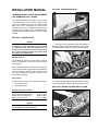
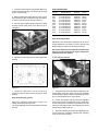
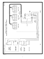
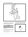
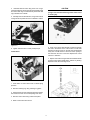
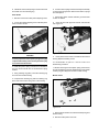
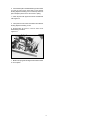
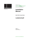
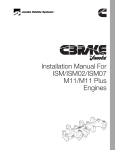
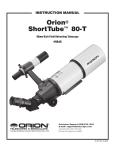
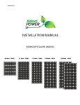
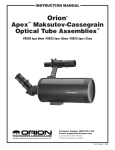
Engine Brakes
Installation
Manual
Model T455B/C Engine Brakes
For Cummins
N14 Series Engines
TecBrake
P.O. Box 27822
Houston, Texas 77227
SECTION 2- ENGINE PREPARATION
INSTALLATION MANUAL
TECBRAKE MODEL T455B/C ENGINE BRAKE
FOR CUMMINS N14 Plus SERIES
The TecBrake T455B/C engine brake may be installed
on popular versions of the Cummins N14Plus series
engine. It can not be installed on the Cummins 855,
88NT, 91N14 STC, 91N14 Celect or 94N14 model
engines. It should only be installed on engines whose
CPL numbers are included in the Application Chart.
TecBrake Model T455B/C replaces the former Model
T455A/B.
SECTION 1- INTRODUCTION
Figure 2-1
NOTICE
The TecBrake Engine Brake is designed as a device
for slowing a vehicle, not stopping it. It is to be used
in conjunction with, but not a substitute for the
vehicle’s service brakes. The service brakes must
be in good operating condition and used to bring
the vehicle to a complete stop.
1. Thoroughly clean engine before beginning installation.
Remove all engine components necessary to permit access
to cylinder heads. Remove valve covers, save the gaskets.
Material Required
The TecBrake kit includes all of the parts required to
make an installation on the most common engine
configurations.
Prior to making installation, determine the engine CPL
number to verify that the engine brake being installed is
correct for the engine. The CPL number can be found on
the engine identification plate that is located on the
engine gear case flange.
Special Tools
Figure 2-2
The following special tools are required for installation:
1. 7/16” 12 point socket
2. Feeler gauge 0.023”
2. Remove the pipe plug from the center web of each rocker
lever housing to allow oil flow into the engine brake housing.
SECTION 3- BRAKE HOUSING INSTALLATION
Recommended Torque Values
Engine Brake Hold-down screws Slave Piston Adj. Screw Nuts Valve Cover capscrews -
70 lbft (95 N*m)
25 lbft (35 N*m)
9 lbft (12N*m)
NOTICE
Injector adjusting screws and exhaust crossheads
are not replaced on this installation.
Figure 3-1
1
1. Install the engine brake housing gaskets. Make sure
that the oil supply slots align correctly with the oil supply
screws in the housings.
APPLICATION CHART
ADJUSTING SCREW
2. Before installing the brake housings, back out the
slave adjusting screws (located above the slave piston)
so that the slave pistons are fully retracted (up).
2025
2026
2027
2389
2390
2391
2398
2590
2591
2592
CPL NO.
3. Place the three engine brake housings on the rocker
housings. Check rocker levers to be sure there is no
interference.
ENGINE MODEL
PART NO.
COLOR
N14 435 ESP Plus
N14 370 ESP Plus
N14 330 ESP Plus
N14 330 ESP Plus
N14 370 ESP Plus
N14 435 ESP Plus
N14 370/460E Plus
N14 330 ESP Plus
N14 370 ESP Plus
N14 435 ESP Plus
TB900032
TB900032
TB900032
TB900039
TB900032
TB900032
TB900032
TB900039
TB900032
TB900032
Orange
Orange
Orange
Purple
Orange
Orange
Orange
Purple
Orange
Orange
Figure 3-4
Slave Piston Adjustment
Adjustment of the slave piston adjusting screw is critical.
Proper adjustment is necessary in order to provide peak
braking efficiency without over stressing the engine.
Slave piston adjusting screw adjustment must be made
with the engine stopped and engine temperature
stabilized below 140 oF (60oC).
Figure 3-2
4. Install the six mounting screws into each engine brake
housing.
A) Dial Indicator Method
Figure 3-3
Figure 3-5
5. Tighten the capscrews to 35 lbft (48 N*m) in
sequence as shown in Figure 3-3 then re-torque to 70lbft
(95N*m).
1. Set engine brake valve lash using the adjusting screw
located above each slave piston. The engine crankshaft
must be rotated to allow the exhaust valve to be fully closed
prior to making adjustment on each cylinder.
Slave Piston Adjusting Screw
2. Install a dial indicator over the slave piston adjusting
screw for the cylinder to be adjusted. Turn the screw down
until the slave piston contacts the crosshead. Zero the dial
indicator on this position. Back out the adjusting screw until
the dial shows 0.023” (0.58mm).
Refer to the Application Chart shown in Figure 3-4 to
identify which screw should be used.
The orange adjusting screws are preinstalled in the brake
housing.
3. Tighten the adjusting screw lock nut to 25 lbft (35 N*m)
torque. Rotate the crankshaft, adjusting each adjusting
screw in firing order sequence.
2
B) Feeler Gauge Method
2.
Bleed air from the engine brake housing.
Accelerate the engine to about 1800 RPM then
release the throttle. Quickly depress the solenoid as
shown to cause the brake to operate. This process
should be repeated 5-6 times on each brake
assembly in order to fill the housings with lube oil.
When all of the air has been removed the brake
should operate immediately when the solenoid is
depressed.
CAUTION
Wear eye protection. When engine is running with
valve covers removed, oil splashing will occur.
Take precautions to prevent oil contaminating
engine and engine compartment.
Figure 3-6
1. Set engine brake valve lash using the adjusting
screw located above each slave piston. The engine
crankshaft must be rotated to allow the exhaust
valve to be fully closed prior to making adjustment
on each cylinder.
SECTION 4- ELECTRICAL SYSTEM INSTALLATION
Installation of the electrical system involves the
mounting of ON/OFF dash switches that have goldplated contacts. Wiring harnesses and wiring diagram
are provided in the control group to complete the
installation. Refer to the wiring diagram Figure 4-1.
2. Back out the adjusting screw on each cylinder
to be adjusted. Using a 0.023" feeler gauge
between the slave piston and the exhaust
crosshead, turn in the slave piston adjusting screw
until a slight drag is felt on the gauge.
Dash Switches
Dash switches should be installed in dash where they
are visible and convenient to operate.
3. Tighten the adjusting screw lock nut to 25 lbft
(35 N*m) torque. Rotate the crankshaft, adjusting
each adjusting screw in firing order sequence.
1. Drill holes in dash to accommodate switches and
install switches with proper name plates.
Operational Check
2. To check the electrical system, start the engine.
and activate engine brake with the ON/OFF switches.
The Celect low speed shut off will prevents the engine
brake from coming on at idle. Accelerate until the
engine reach 1800 RPM and release the throttle. The
center engine brake housing should operate with one
ON/OFF switch. Repeat this operation for the
remaining 2 and 3 positions. The front and rear brake
housings should operate with the other ON/OFF
switch, and all three engine brake housings should
operate with both ON/OFF switches. After this
procedure, shut down engine.
Installation of the brake housings is now complete.
Functioning of the brakes should be checked before
proceeding further.
1. Start the engine and let it idle for a short time.
3. To complete the installation, reinstall the Cummins
valve cover gaskets, replace valve covers, and all
previously removed parts. Torque valve cover
capscrews to 9 lbft (12 N*m).
Figure 3-7
3
Figure 4-1
4
SECTION 5 - ENGINE BRAKE MAINTENANCE
Figure 5-1
3. Clean solenoid bore with solvent and wipe dry with
paper towel. Be careful not to leave any lint or residue in
bore that may contaminate brake hydraulic components.
The engine brake is designed to be trouble free and does
not require special maintenance. During regularly
scheduled maintenance, or if a problem occurs, the
procedures described below should be followed.
CAUTION
Do not remove any engine brake component while
the engine running. This may result in personal injury.
Use only approved cleaning solvents.
Solenoid Valve
1. Disconnect the electrical lead from the solenoid and
remove solenoid with a spanner wrench. Remove and
discard the three rubber seal rings.
2. Clean the filter screen and solenoid with solvent
then dry with low air pressure.
Figure 5-2
5
CAUTION
4. Reinstall solenoid valve using three new o-rings.
Coat solenoid body with engine lube oil and install upper
and center seal rings on solenoid body. Seat lower seal
ring in bottom bore of brake.
Control valve covers are under load from control valve
springs. Use care when removing control valve covers
to avoid injury.
5. Carefully screw in solenoid valve, using care to assure
O-rings remain in position and are not twisted or "rolled".
Figure 5-5
Figure 5-3
6. Push on the check valve ball with a small wire through
the hole in the bottom of the control valve to make sure
that there is spring tension on the ball. The ball should lift
freely with a small amount of force and return quickly to
the seat when the force is removed. Replace the control
valve if it is defective.
6. Tighten solenoid valve to 5 lbft (7 N*M) torque.
Control Valve
7. Dip the control valve in engine lube oil and install in brake
housing. Control valve should slide in without any binding.
Replace control valve if binding occurs.
Figure 5-4
1. Press down on control valve cover to relieve spring
pressure.
2. Remove retaining ring using retaining ring pliers.
3. Slowly remove the cover until spring pressure ceases,
then remove the two control valve springs and collar.
4. Remove control valve using needle nose pliers.
Figure 5-6
5. Wash control valve with solvent.
6
8. Install both control valve springs in control valve bore
and install cover and retaining ring.
6. Loosen screw in spring removal tool slowly and carefully
to remove the spring tension. Remove the retainer, springs
and slave piston.
Slave Piston
1. Remove lock nut from slave piston adjusting screw.
7. Check slave piston outside diameter ground surface
for burs or defects.
2. Loosen slave piston adjusting screw until slave piston
seats on bottom of bore.
8. Clean all parts with approved solvent and lubricate
with engine oil.
Figure 5-7
Figure 5-9
CAUTION
When removing slave pistons wear eye protection
and use proper tools. Slave piston springs are highly
compressed and may cause serious personal injury
if not removed with caution.
9. Insert piston in bore. Piston must slide in bore without
binding. Replace if binding occurs.
10. Reassemble all par ts in reverse order from
disassembly procedure.
3. Install slave piston spring removal tool as illustrated.
Turn tool screw until all force is removed from spring
retainer.
11. Before removing the slave piston spring removal tool,
be sure the retaining ring is fully seated in the groove. Rotate
retaining ring 90o away from the slot in brake housing.
4. Using retaining ring pliers, orient the retaining ring
end near slot in brake housing.
Master Piston
5. Compress the retaining ring with the retaining ring
pliers and remove it from the groove in the housing.
Figure 5-10
Figure 5-8
1. Remove button head screw, washer and flat spring from
brake housing.
2. Remove master piston from bore.
7
3. Check master piston outside diameter ground surface
for nicks or burrs. Piston must slide in bore without
binding. Replace if binding occurs. Check top surface of
piston. Replace piston if there are cracks or pitting.
4. Clean all parts with approved solvent and lubricate
with engine oil.
5. Insert piston in bore. Piston must slide in bore without
binding. Replace if binding occurs.
6. Reassemble all par ts in reverse order from
disassembly procedure.
Figure 5-11
7. Make sure spring tabs are aligned with raised surface
on end of piston.
8
Cummins® and Celect® are registered trademarks of Cummins Engine Co. Inc.
TecBrake Inc.
P.O. Box 27822
Houston, Texas 77227
©1999 TecBrake
Bulletin No. TB990170A
05/20/99