1
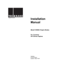
brought to you by:
DIESELUSAGROUP®
get more at www.DieselUSA.com
Engine Brakes
Installation
Manual
Model T346A Engine Brakes
For Caterpillar 3406, 3406B
And 3406C Series Engines
TecBrake
P.O. Box 27822
Houston, Texas 77227
get more info at: www.DieselUSA.com
Recommended Torque Values
Bridge Adj. Screw lock nuts24 lbft (32 N*m)
Cylinder Head Bolts330 lbft (450 N*m)
Engine Brake Hold-down nuts100lbft (135 N*m)
Engine Brake 7/16” cap screws60lbft (82 N*m)
Rocker Arm Adj. Screw nuts22 lbft (30 N*m)
Slave Piston Adj. Screw nuts16 lbft (22 N*m)
Fuel Lines30lbft (41 N*m)
INSTALLATION MANUAL
TECBRAKE MODEL T346A ENGINE BRAKE
FOR CATERPILLAR 3406, 3406B AND 3406C
SERIES ENGINE
SECTION 1-INTRODUCTION
SECTION 2 - ENGINE PREPARATION
The TecBrake T346A engine brake may be installed on
Caterpillar model 3406, 3406B and 3406C series engine.
These engines although similar, were produced with
variations that affect the components required and the
installation procedure.
NOTICE
The TecBrake Engine Brake is designed as a device
for slowing a vehicle, not stopping it. It is to be used
in conjunction with, but not a substitute for the
vehicle’s service brakes. The service brakes must
be in good operating condition and used to bring
the vehicle to a complete stop.
Material Required
Figure 2-1
The TecBrake kit includes all of the parts required to
make an installation on the most common engine
configurations. An optional shim & washer kit (Part No.
TJ013677) is required on all engines with a serial number
lower than 7FB39279, or with a 92U prefix. This is not
included with the engine brake kit and must be ordered
separately. Refer to the identification plate on valve cover
for required data.
1. Thoroughly clean engine before beginning installation.
Remove all engine components necessary to permit access
to cylinder heads.
The TecBrake kit does not contain a control group. Five
different control groups are available to cover all
applications. These groups must be ordered separately
in addition to the basic kit.
Refer to the TecBrake Parts Manual for additional
information.
Special Tools
Figure 2-2
The following special tools are required for installation:
1.
2.
3.
4.
TecBrake Tools
Feeler gage-0.080”
Feeler gage-0.067”
Feeler gage-0.060”
Feeler gage-0.090”
1.
2.
3.
4.
5.
Caterpillar Tools
Caterpillar P/N.
Fuel Line Socket-Flank Drive 3/4”
5P144
Fuel Line Wrench-7/8”
5P5195
Timing Pin-Fuel Pump (3406)
8S2291
Timing Pin-Fuel Pump (3406B)
6V4186
Turning Tool
9S9082
2. Remove the upper valve covers.
TecBrake P/N.
TB900005
TB900006
TB900004
TJ018488
Figure 2-3
3. Remove the valve cover base.
1
get more info at: www.DieselUSA.com
NOTICE
Follow procedure specified below to set engine to
cylinder No.1 T.D.C. compression. This procedure
will allow three cylinders to be adjusted for both
valves and engine brakes without rotating the
engine. One additional rotation to cylinder No 6
T.D.C. compression will be required to adjust the
other three cylinders.
6. Insert timing bolt in location shown and rotate engine
using the Caterpillar Turning Tool counter clockwise (looking
from the flywheel side of the engine) until the timing bolt is
aligned with the threaded hole in the flywheel. When the
timing bolt can be threaded into the tapped hole in the
flywheel, the engine is at T.D.C. cylinder No. 1. Look at
both valves on cylinder No. 1 to see if they are both closed.
If closed, cylinder No. 1 is on the compression stroke. If
not, remove the timing bolt and rotate the engine 360
degrees until the timing bolt is aligned with the thread in
the tapped hole.
Timing Bolt Method to obtain T.D.C.
Figure 2-4
Figure 2-7
4. From just above the starter, remove the timing bolt
from its storage location and the access plate to the
flywheel.
7. Check both rocker arms on cylinder No. 1 to make sure
there is clearance by moving the rocker arms up and down.
This insures cylinder No.1 is on the compression stroke.
NOTICE
If the access to the flywheel is not available, then an
optional method that is described below can be used.
Fuel Pump Method to obtain T.D.C.
1. Remove the plug from the fuel injection pump as shown
in Figure 2-8
Figure 2-5
5. Insert the Caterpillar Turning Tool P/N 9S9082 as
shown.
Figure 2-8
2. Select correct timing pin identified in section one - special
tools.
Figure 2-6
3. Insert timing pin in hole in fuel pump and slowly rotate
crankshaft counterclockwise until pin drops into slot.
2
get more info at: www.DieselUSA.com
3. Install plastic plugs in open fuel lines.
The engine is now at cylinder No. 1 top dead center
compression stroke.
CAUTION
Do not bar engine with timing pin inserted in fuel
pump. Pin may be sheared off and cause engine
damage.
Figure 2-11
Rocker Arm Removal
CAUTION
Install only one brake housing at a time to avoid
removing all six engine head bolts at once. Removing
six head bolts can cause head seating problems.
Figure 2-9
4. Mark crankshaft vibration damper to locate cylinder
#1 T.D.C. This mark will be required after engine brake
assembly for engine valve and engine brake adjustment.
5. Remove timing pin from fuel pump and install seal
plug back in pump.
Removal Of Fuel Tube
CAUTION
Avoid any contamination of fuel lines or nozzle
assemblies. Fuel contamination after fuel filters can
cause engine damages.
Figure 2-12
1. Loosen rocker arm adjusting screw locknuts.
2. Remove rocker arm hold-down bolts. Save washers for
reassembly.
Figure 2-10
1. Remove fuel lines using Caterpillar’s fuel line wrench.
Figure 2-13
2. Install protective caps on nozzle assemblies and put
fuel lines in clean plastic bags.
3. Remove the rocker arm assembly from the engine.
3
get more info at: www.DieselUSA.com
2. Level the TecBrake exhaust valve bridges :
a)
b)
c)
d)
e)
f)
g)
Figure 2-14
Press on center of bridge with finger.
Loosen adjusting screw a couple of turns to insure
screw is not contacting valve stem.
Turn adjusting screw clockwise until contact with the
valve stem.
Turn adjusting screw an additional 30 degrees
(approximately ½ flat of screw).
Hold adjusting screw in position and torque jam nut to
24 lbft (32N*M).
Apply clean engine lubrication oil to top of bridge where
rocker arm contacts.
Adjust (3) intake valve bridges using same procedure
as above.
4. Remove the exhaust valve bridges from the engine.
Figure 2-17
3. Verify there is at least 0.020” minimum clearance between
the bridge body and valve spring retainers on both sides of
bridge.
Figure 2-15
5. Back out the bridge adjusting screw. Leave loose; do
not tighten until placed on engine for leveling.
Changing Exhaust Rocker Adjusting Screws
Bridge Leveling Procedure
Figure 2-18
Figure 2-16
1. Remove the slotted Caterpillar exhaust rocker adjusting
screws from the rocker arm.
1. Lubricate bore of exhaust valve bridge with clean
engine lubrication oil prior to installation on engine. Install
TecBrake exhaust bridges on the engine.
2. Remove jam nuts from rocker adjusting screws.
4
get more info at: www.DieselUSA.com
3. Place jam nuts on TecBrake exhaust rocker adjusting
screws.
Figure 2-21
Figure 2-19
4. Apply clean engine lube oil to the end of the TecBrake
Oil Supply Adapter.
4. Install the TecBrake exhaust rocker screw in the
exhaust rocker arm.
5. Insert adapter in removed dowel pin hole, making sure
pedestal and rocker shafts holes aline.
5. Discard the Caterpillar slotted adjusting screws.
6. Complete adapter installation by using a plastic hammer
to tap adapter down until large O.D. contacts rocker pedestal.
Do not install “O” ring on adapter at this time.
Removal of Dowel Pin
Rocker Arm Assembly Installation
Figure 2-20
1. Place Dowel Pin Removal Tool in position to remove
the dowel pin that is located on the front end (fan side) of
the rocker shaft assembly.
Figure 2-22
1. Blow out oil that has gotten into cylinder head bolt holes
using compressed air with a suitable length of hose attached
to a nozzle. Use a clean rag to cover area to avoid oil from
spraying.
2. Clamp dowel pin in dowel pin removal tool.
3. Remove dowel pin by tightening the two jacking screw
in small equal increments (approximately ¼ turn each).
This process must be repeated on the other rocker shaft
assembly, also on the front end (fan side).
CAUTION
Eye protection must be worn. Personal injuty can result
if safety glasses are not used. Oil Must be blown out
of cylinder head bolt holes to prevent the engine block
from cracking when torquing of TecBrake hold-down
stud.
NOTE
The dowel pins that are being removed are located
at cylinder # 1 and cylinder # 4.
2. Apply clean engine oil to threads of the TecBrake studs
and contact area on top of pedestal, washer and stud hex.
5
get more info at: www.DieselUSA.com
1. Remove the two cylinder head bolts as shown on Figure
2-25 to install TecBrake outer support bracket.
3. Install two TecBrake studs on each end of the rocker
assembly using the washer marked “A” between the head
of the stud and the rocker support bracket.
4. Insert the rocker adjusting screws into the push tube
ends.
Figure 2-26
2. Blow out oil that has gotten into cylinder head bolts using
same procedure described before.
Figure 2-23
3. Apply clean engine oil to head bolt threads and to under
side of bolt hex and washer. Install support bases as
illustrated above. The boss on the bottom of the support
base will fit into cylinder head expansion hole to locate base.
CAUTION
Prevent damaging lead wires on engines equipped
with glow plugs when installing rocker assemblies.
4. Torque the head bolts to 200 lbft (270 N*M). Torque the
head bolts to 330 lbft (450N*M).
SECTION 3 - BRAKE HOUSING INSTALLATION
Engines with serial numbers lower than 7FB39279 and all
92U prefix engine require a procedure that is described in
“Leveling Procedure” on page #15 of this manual. Each
engine brake kit has a front and rear housing that is
identified by the plate attached to the top of the housing.
The front housing must be installed on the front three
cylinders (fan end) of the engine and the rear housing on
the rear three cylinders of the engine.
Figure 2-24
1. Install the spacer marked “B” on the brake hold down
stud as illustrated below.
5. Center rocker assembly about TecBrake studs when
tightening studs. Bolt rocker assembly firmly in place when
centered. Torquing procedure: Start with center bolt then
change to ends. Begin torquing sequence at 200 lbft
(270 N*M) and continue to increase toque at 50 lbft (70
N*M) increments until specification of 330 lbft (450 N*M)
is obtained.
Support Bracket Installation
Figure 3-1
Figure 2-25
6
get more info at: www.DieselUSA.com
Fuel Tube Installation
CAUTION
Do not bend or modify fuel lines as fuel leakage may
result. When installing new fule lines, use new
O’rings lubricated with clean engine oil.
2. Remove protective plug and cap from the fuel lines
and nozzles.
3. Hand tighten all fuel lines.
Figure 3-4
6. Prior to placing engine brake housing on engine, loosen
slave piston adjusting screws until slave pistons are seated
in bores. Locate brake housing on the two studs and lower
brake slowly to locate oil supply adapter into brake housing.
Figure 3-2
4. Torque to 30 lbft (41N*M) using the Caterpillar fuel
line socket wrench.
NOTE
Adequate clearance must be maintained between
the fuel line and the TecBrake hold down stud. After
torquing, a clearance of 0.125 in. (3.175mm) min. to
0.375 in. (9.525mm) max. is required. Repositioning
or interchanging of fuel lines may be required to
maintain the required clearance.
Figure 3-5
7. Place the spacer tubes between the housing and the
installed lower support bases. Install the two 7/16” bolts
with washers, taking care to align the tubes with the tapped
holes in the support bracket.
Figure 3-3
5. Apply a small amount of grease on O-ring and oil
supply adapter and carefully slid O-ring into groove in oil
supply adapter.
Figure 3-6
8. Install the 3/4” washers and nuts on the hold down studs.
Hand-tighten the nuts into the stud. Torque the engine brake
fasteners to the following specifications:
7
get more info at: www.DieselUSA.com
CAUTION
For optimum performance and to prevent engine
damage make sure that correct lash is selected and
care is taken in adjustment procedure. Slave piston
adjustment must be done when engine temperature is
stabilized and cold and not running. A cold engine is
defined when engine coolant temperature is below 140
degrees F (60 degrees C).
Torque hold down nuts to 60 lbft 882 N*M). Torque the
7/16” capscrews to 60 lbft (82 N*M). Torque again the
hold down nuts to 100 lbft (135 N*M).
NOTE:
Check to make sure fuel lines have clearance
between brake and engine components. Reposition
fuel lines if necessary.
Engine Model
Yr./Prefix
3406 92U
3406B Pre-91 4MG,
5YG, 7FB, 8TC
3406B 3ZJ16181 &
below
3406B 3ZJ16181 &
below
3406C 3ZJ16182 &
greater
3406C 3ZJ16182 &
greater
3406B 5KJ
3406B 5KJ
3406C 5KJ
3406C 5KJ
3406C 8PN
9. Use same procedure on the other engine brake
housing installation.
10. Both engine brake housings should now be installed.
The next step is to adjust the exhaust and intake valves
on the engine and the slave pistons of the engine brake.
The engine position should be on cylinder #1 TDC
compression stroke to start the adjustment procedure.
Valve Adjustment Procedure
Engine
Rating (HP)
All
All
Slave
Lash
0.060” (1.52 mm)
0.080 in. (2.03mm)
All except 400
0.080 in. (2.03mm)
400
0.067 in. (1.70mm)
310-350
0.080 in. (2.03mm)
365-460
0.090 in. (2.28mm)
All except 400
400
310-350
365-460
All
0.080 in. (2.03mm)
0.067 in. (1.70mm)
0.080 in. (2.03mm)
0.090 in. (2.28mm)
0.080 in. (2.03mm)
Table 3.2
Figure 3-7
Engine
Position
Cyl. 1 TDC
Cyl. 6 TDC
Table 3.1
Set Int.
Valve Cyl.
1,2,4
3,5,6
Set Exh.
Valve Cyl.
1,3,5
2,4,6
Set Lash.
Slave Cyl.
1,3,5
2,4,6
1. Using the table above, set the exhaust and intake
valves that can be set when cylinder #1 is at TDC. Set
intake valves to 0.015” (0.38mm) and exhaust valves to
0.030” (0.76mm). Review engine manual to confirm valve
setting values. After setting the valves, the slave piston
lash can be set on the cylinders specified. When setting
slave lash, the exhaust bridge and exhaust rocker must
be loose and have clearance.
Figure 3-8
2. Insert correct feeler gauge between both feet of the slave
piston and the crosshead bridge. Lossen slave piston jam
nut and screw down slave piston adjusting screw until a slight
drag is felt when the feeler gauge is moved. Torque jam nut
to 16 lbft (22 N*M). Finish adjusting the two engine position.
2. Torque rocker adjusting screw jam nut to 22 lbft (30
N*M).
3. Remove timing bolt and rotate engine one revolution
(360 degrees) and reinstall timing bolt. Now engine is at
cylinder # TDC. Finish adjusting exhaust, intake and slave
piston settings for the remaining three cylinders.
Slave Piston Adjusting Procedure
1. Select correct slave lash (Table 3.2) and cylinders to
be adjusted from table 3.1
4. Remove timing bolt and install timing bolt and access
cover to proper location.
8
get more info at: www.DieselUSA.com
Lower Base/ Spacer Installation
4. Torque spacer studs and the other two bolts securing
the spacer to 10 lbft (13.5 N*M).
Figure 3-9
Figure 3-12
1. Install both lower cover bases on engine and check
for possible interference between cover internal bosses
and exhaust bridges on cylinder #3 and cylinder #6. If
there is any interference, remove base and grind lower
cover base to provide clearance.
5. Install electrical terminal lead-out assembly in spacer with
a six point socket. Tighten until terminal assembly hex
contacts spacer.
CAUTION
Do not grind exhaust valve bridge to provide
clearance. Grinding bridge will reduce strength and
may cause severe engine damage.
Figure 3-13
6. Install the TecBrake gasket in spacer. Gasket length will
have to be trimmed after assembly.
Figure 3-10
2. Attach the lower cover base with the four supplier
mounting studs and washers. Install the short-threaded
end of the stud into the cylinder head. The figure above
shows the location of the studs.
Figure 3-14
7. Install valve cover spacer on lower base using vibration
resistant nuts supplied in the kit on the four mounting studs.
Torque both studs and nuts to 13 lbft (18 N*M).
Figure 3-11
3. Install Caterpillar screws on remaining locations.
9
get more info at: www.DieselUSA.com
2. When engine is at low idle, condition press top of solenoid
six or seven times to bleed all air trapped in the engine
brake housing.
Final Check
NOTE
Make sure there is no fuel or oil leaks and observe that
all master pistons are operating. Make sure that there
are no component interference and that all electrical
connections are secure. If engine fails to start or
misfires, air is trapped in fuel system. Follow
procedure in Caterpillar Service Manual to eliminate
trapped air.
Figure 3-15
8. Install the two serrated screws in the location
shown in the above figure. Torque the cap screws
to 13 lbft (18 N*M).
Figure 3-18
1. Prior to replacing valve cover, check to make sure that
no interference exists between the valve cover bosses near
the oil filler and breather locations and the engine brake
housing. If interference is found, remove sufficient material
from the valve cover for clearance.
Figure 3-16
9. Connect solenoid harness as shown
NOTICE
Check to make sure all required adjustments have
been made and there is no interference with fuel lines.
Engine Brake Test
WARNING
Use eye protection when operating engine without
valve covers. Hot oil splashing from the engine
overhead may cause personal injury. Take
precautions to control oil leaking from engine when
operating without valve covers.
Figure 3-19
2. Install valve covers. Torque capscrews to 13 lbft (18
N*M).
NOTE
On Dit and PCT engines only, a boss that is located on
the bottom of the crossover pipe may interfere with the
valve cover after engine brake installation. To eliminate
this interference, grind off boss. Clean parts and
reassemble. If relocation of the breather pipe is required,
make sure breather pipe is adequately secured.
Figure 3-17
1. Run the engine for 10 minutes for warm up.
10
get more info at: www.DieselUSA.com
Housing Leveling Procedure
NOTE
Housing leveling is required on 3406B engines with
serial numbers lower than 7FB39279 and on all 92U
prefix engines.
Figure 3-22
7. Remove the 7/16” capscrews, washers, tubes and engine
brake housing from the engine.
Figure 3-20
1. Install TecBrake Mounting Washers marked “A” on
studs as illustrated above.
2. Prior to installing brake housing, slave piston adjusting
screws must be loosened and backed out until slave piston
is seated on bottom of bore.
3. Carefully install brake housing on engine. Pay special
attention to make sure oil supply adapter is aligned with
bore on bottom of housing.
4. Locate support tubes under the two outside supports.
Insert the two 7/16” capscrews with washers through
the engine brake housing and tubes and into support
base.
Figure 3-23
8. Measure the thickness of the shim pack supplied. The
shim pack is comprised of a number of shims .003” (0.08
mm) thick that are bonded together (laminated).
5. Torque cap screws to 10 ftlb (13 N*M) for shim
measurement purposes only.
Figure 3-24
Figure 3-21
9. With sharp knife remove shim laminations from the shim
packs to satisfy the measured gap that was previously
recorded at the four housings locations. The final shim pack
thickness must be within .003” (0.08mm) of the actual gap
measured.
6. After both housings are installed, measure gap that
exist between the “A” washers that were installed on the
studs and the mounting surface of the engine brake
housing. Record all measurements for all four locations.
11
get more info at: www.DieselUSA.com
CAUTION
Shim and washer must be stacked exactly as
specified below or shims will be damaged by the
recess cut on the bottom mounting surface of the
engine brake housing.
2. Mount the clutch switch in a convenient location near
the clutch pedal so that movement of the clutch pedal will
contact the clutch switch actuator arm.
See Figure 4-1.
3. Adjust the clutch switch so that the actuator arm is
deflected from 1" to 1.5" (25 mm to 38 mm) when the clutch
is in the up (clutch engaged) position.
4. Check the switch by depressing the clutch. The switch
should “click” to an open electrical position as soon as the
free play in the clutch is taken up. When the clutch is released,
the switch should “click” to a closed electrical position.
5. If using the foot switch, install foot switch in a convenient
cab location at reach of operator left foot.
NOTE
Vehicles with automatic transmission require pressure
switch. Contact TecBrake distributor for details.
Figure 3-25
Fuel Pump Switch (External)
10. Remove the TecBrake washer marked “A” from the
mounting stud as shown. Next, place the correct shim
pack that corresponds with the measured gap of that
particular mounting stud. Install the “A” washer on top of
the laminated shim pack. Repeat this procedure for all
stud locations. Continue the installation by going back to
Section 3 Brake Housing Installation
SECTION 4 - ELECTRICAL INSTALLATION
Dash Switches
1. Dash switches should be installed in dash where they
are visible and convenient to operate.
2. Drill holes in dash to accommodate switches and install
switches with proper name plates.
Mechanical Control Engines
Figure 4-2
Clutch Switch
1. Attach fuel pump switch assembly to the fuel pump in
the location illustrated above.
Figure 4-1
Figure 4-3
1. It is recommended that the clutch switch be mounted
inside the vehicle cab to protect it from road contamination.
2. Install the actuating arm on the fuel control throttle lever
as illustrated above.
3. Adjust lever to actuate switch when throttle arm is
moved to the idle fuel position.
12
get more info at: www.DieselUSA.com
CAUTION
Check throttle linkage to make sure it moves freely
after installation of fuel pump switch assembly.
3. Start the engine and check low idle RPM. Disconnect
the throttle linkage and adjust the idle per Caterpillar
specifications.
4. Tighten locknut to 5 lbft. (7 N*m). Reconnect throttle
linkage.
5. TecBrake Internal switch has a double diode configuration,
harness wires can be connected to either switch terminal.
PEEC I Control Engines
1. Install all hardware supplied following the specific
instructions included in the Control Group
PEEC III ABS & NON ABS Control Engines
Figure 4-4
1. Install all hardware supplied following the specific
instructions included in the Control Group
NOTE
Check diode on fuel pump micro switch to be sure
the diode position is correct for your vehicle system
ground. See sketch below for diode check.
Wiring
1. Complete all wiring per diagram included on each Control
Group.
Fuel Pump Switch (Internal)
SECTION 5 - ENGINE BRAKE MAINTENANCE.
The engine brake is designed to be trouble free and does
not require special maintenance. During regularly scheduled
maintenance, or if a problem occurs, the procedures
described below should be followed.
CAUTION
Do not remove any engine brake component while the
engine running. This may result in personal injury. Use
only approved cleaning solvents.
Figure 4-5
1. Remove the fuel pump low idle screw. Install the seal,
washer and locknut from the screw on the switch.
Figure 5-1
Figure 4-6
Solenoid Valve
2. Install the switch to about same depth as the idle screw
was turned.
1. Disconnect the electrical lead from the solenoid.
2. Remove solenoid with a TecBrake wrench.
3. Remove and discard the three rubber seal rings on the
solenoid body.
13
get more info at: www.DieselUSA.com
4. Clean the oil screen and solenoid body with an
approved solvent.
5. Dry solenoid with low pressure air.
6. Clean solenoid bore in brake with solvent and wipe
dry with paper towel. Be careful not to leave any lint or
any other residue in bore that may contaminate brake
hydraulic components.
Figure 5-4
2. Remove control valve with needle nose pliers. Wash
control valve with an approved solvent.
Figure 5-2
7. Reinstall solenoid valve with three new seal rings.
Coat solenoid body with engine lube oil and install upper
and center seal rings on solenoid body. Set lower seal
ring in engine brake housing bottom bore.
8. Carefully screw in solenoid to insure seal rings
remain in position without being twisted.
Figure 5-5
3. Push on the check valve ball with a small wire through
the hole in the bottom of the control valve to make sure the
ball. The ball should lift freely with a small amount of force
and return quickly to the seat when force is removed.
Replace control valve if defective.
Figure 5-3
9. Torque solenoid valve to 5 lbft (7N*M).
Control Valve
CAUTION
Control valve covers are under load from control
valve springs. Use care when removing control valve
covers to avoid injury
1. Remove the button head cap screws from the control
valve covers.
Figure 5-6
14
get more info at: www.DieselUSA.com
4. Dip control valve in engine lube oil and install in brake
housing. Control valve should slide in bore without any
binding. Replace control valve if binding occurs.
6. Compress retaining ring with retaining ring pliers and
remove from groove in housing.
7. Loosen screw in tool slowly and carefully to remove
spring tension. Remove retainer, springs and slave piston.
5. Install both control valve springs in each control valve
bore and install cover with button head capscrew.
8. Clean all parts with approved solvent. Check slave
piston ground O.D. for any burrs or defects. Piston must
slid in bore without binding. If any binding occurs replace
piston.
Slave Piston
WARNING
Safety glasses must be used. Springs in slave
pistons are highly compressed and may cause
serious personal injury if not removed with caution
and proper spring removal tool.
9. Assembly all parts reversing the above disassembly
procedure.
Master Piston
Figure 5-7
1. Remove jam nut from slave piston adjusting screw.
Figure 5-9
2. Loosen slave piston adjusting screw until slave piston
seats on bottom of bore.
1. Remove button head screw, washer and flat spring from
brake housing.
3. Install slave piston spring removal tool as illustrated
in figure above.
2. Remove master piston from bore
3. Check ground O.D. for nicks or burrs. Piston must slide
in bore without binding. Replace piston if required.
4. Turn tool screw until all force is removed from spring
retainer.
4. Check carbide wear surface for pitting or cracks.
Replace piston if carbide surface is cracked or pitted.
5. Clean piston with approved solvent. Dip the master
piston in engine lube oil.
6. Insert master piston in brake housing bore.
7. Check to insure piston slides in bore without any
binding.
8. Replace master piston if tight in bore.
9. Reassemble master piston spring, washer and button
head screw in reverse order.
Figure 5-8
10. Tighten button head screw. Take care to aline spring
tabs concentric with center of raised wear surface on end
of piston.
5. Using retaining ring pliers, orient retaining ring end
near slot in brake housing.
15
get more info at: www.DieselUSA.com
Slave Piston Adjusting Screw
Figure 5-10
1. Remove the slave piston, adjusting screw from the
brake housing.
2. Check adjusting screw to be sure plunger is free to
move in both directions with light force applied. Internal
spring force must hold the plunger extended. Do not
disassembly with new adjusting screw if defective.
16
get more info at: www.DieselUSA.com
Cat®, and Caterpillar are registered trademarks of Caterpillar Inc.
Tec Brake Inc.
P.O. Box 27822
Houston, Texas 77227
©1999 Tec Brake
Bulletin No. TB990107A
get more info at: www.DieselUSA.com
11/15/99