1
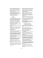
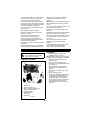
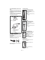
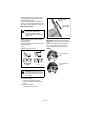
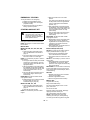
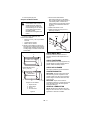
Walk Behind Lawn Mower Owner/Operator Manual Models 911099 - LM21SH 911101 - LM21SWH 911102 - LM21SCH 911330 - LM21SW 911331 - LM21SE 911514 - LM21S 911515 - LM21SE 911525 - LM21SW 911526 - LM21SC 911531 - LM21S ENGLISH FRANÇAIS ESPAGNOL Transfer model & serial number label from product registration here. Coller l’autocollant du modèle et du numéro de série dans cet encadré. Transferir aquí la etiqueta del modelo y número de serie del registro del producto. 01241400A 11/03 Supersedes 01241400 Printed in USA Ariens Company 655 West Ryan Street P.O. Box 157 Brillion, Wisconsin 54110-0157 USA Telephone (920) 756-2141 Facsimile (920) 756-2407 MODEL CERTIFICATE OF CONFORMITY ISSUED BY THE MANUFACTURER – MODÈLE DE CERTIFICAT DE CONFORMITÉ DÉLIVRÉ PAR LE FABRICANT – VOM HERSTELLER HERAUSGEGEBENE MUSTERÜBEREINSTIMMUNGSBESCHEINIGUNG – MODEL CONFORMITEITSCERTIFICAAT UITGEGEVEN DOOR DE FABRIKANT – OVERENSSTEMMELSESCERTIFIKAT FOR MODELLER, UDSTEDT AF FABRIKANTEN – DICHIARAZIONE DI CONFORMITÀ DEL PRODOTTO RILASCIATA DAL PRODUTTORE – MODELO DE CERTIFICADO DE CONFORMIDAD EMITIDO POR EL FABRICANTE – MODELLENS SAMSVARSBEVIS UTSTEDT AV PRODUSENTEN – INTYG OM ÖVERENSSTÄMMELSE FÖR MODELLER UTFÄRDAT AV TILLVERKAREN – VALMISTAJAN ANTAMA MALLIN VAATIMUSTENMUKAISUUSTODISTUS – ŚWIADECTWO ZGODNOŚCI MODELU WYDANE PRZEZ PRODUCENTA – CERTIFICADO DE CONFORMIDADE DO MODELO EMITIDO PELO FABRICANTE We the undersigned, ARIENS COMPANY, certify that: Nous, soussignés ARIENS COMPANY, certifions que : Der Unterzeichnete, ARIENS COMPANY, bescheinigt, dass: Wij, de ondergetekenden, ARIENS COMPANY, verklaren dat: Undertegnede, ARIENS COMPANY, attesterer, at: La sottoscritta società ARIENS COMPANY certifica che: Nosotros, los abajo firmantes, ARIENS COMPANY, certificamos que: Undertegnede, ARIENS COMPANY, bekrefter at: Undertecknad, ARIENS COMPANY, intygar att: Allekirjoittanut, ARIENS COMPANY, vakuuttaa, että: My, nijej podpisani, ARIENS COMPANY, oświadczamy, że: Nós, abaixo assinados, certificamos em nome da ARIENS COMPANY, que: Type: Type : Typ: Type: Type: Tipo: Tipo: Type: Typ: Tyyppi: Typ: Tipo: Walk Behind Lawn Mower – Tondeuse à gazon autotractée – Handgeführter Rasenmäher – Duwgrasmaaier – Selvkørende plæneklipper – Tosaerba semovente – Cortacésped de empuje manual – Gressklipper – Självgående gräsklippare – Käsinohjailtava ruohonleikkuri – Kosiarka trawnikowa – Cortador de Relva Convencional Trade Name: Appellation commerciale : Handelsbezeichnung: Handelsnaam: Ariens Firmanavn: Nome commerciale: Nombre comercial: Handelsnavn: Handelsbeteckning: Kauppanimi: Nazwa handlowa: Nome da Marca: 911330 911331 911514 911515 Model: Modèle : Modell: Model: Model: Modello: Modelo: Modell: Modell: Malli: Model: Modelo: Serial # Range: Plage de numéros de série : Seriennummern: Serienummerreeks: Serienummerområde: Gamma n. di serie: Rango de nº de serie: Serienummerområde: Serienummerområde: Sarjanumerot: Zakres, numer seryjny: Faixa de Nº de Série: Conforms to: Est conforme à : Mit den Anforderungen der folgenden Richtlinien übereinstimmt: Voldoet aan: Er i overensstemmelse med: È conforme a: Cumple con: Er i samsvar med: Överensstämmer med: Täyttää seuraavat vaatimukset: Jest zgodny z: De acordo com: Notified Body – Organisme notifié – Zertifizierungsstelle – Aangemelde instantie – Bemyndiget organ – Organismo notificato – Organismo notificado – Teknisk kontrollorgan – Anmält organ – Ilmoitettu laitos – Organ zaświadczający – Organismo Certificador – 2 911525 911526 911531 911330 Š 000101 911331 Š 000101 911514 Š 020500 911515 Š 005001 911525 Š 008300 911526 Š 009501 911531 Š 000101 98/37/EC, 89/336/EEC, 2000/14/EC (VIII) SNCH/TUV Rheinland 11, Route de Luxembourg L-5230 Sandweiler Representative Measured Sound Power Level (Lwa) Niveau de puissance acoustique représentatif Guaranteed Sound Power Level (Lwa) – Niveau de puissance acoustique garanti (Lwa) – mesuré (Lwa) Repräsentativer gemessener Geräuschpegel Garantierter Geräuschpegel (Lwa) – Gegarandeerd (Lwa) Representatief gemeten geluidsniveau (Lwa) geluidsniveau (Lwa) – Garanteret støjeffektniveau (Lwa) – Repræsentativt, målt støjeffektniveau (Lwa) Livello di Livello di potenza sonora garantito (Lwa) – Nivel de potenza sonora rappresentativo rilevato (Lwa) Nivel de potencia acústica garantizado (Lwa) – Garantert potencia acústica representativo medido (Lwa) lydeffektnivå (Lwa) – Garanterad uppmätt ljudnivå (Lwa) – Representativt målt lydeffektnivå (Lwa) Representativ Taattu äänitehotaso (Lwa) – Gwarantowany reprezentatywny uppmätt ljudnivå (Lwa) Tyypillinen mitattu äänitehotaso poziom mocy akustycznej (Lwa) – Nível de Potência de (Lwa) Zmierzony reprezentatywny poziom mocy Som Garantido (Lwa) – akustycznej (Lwa) Nível de Potência de Som Medido Representativo (Lwa) 330, 331, 514, 515, 525, 531: 99 dBA 330, 331, 514, 515, 525, 526, 531: 100 dBA 526: 98 dBA Philip J. Smucker: Manager of Product Conformance (Keeper of Technical File) Responsable de la conformité des produits (Dépositaire de la fiche technique) Manager of Product Conformance (Archivar der technischen Akte) Manager Productconformering (Beheerder van technische bestand) Produktoverensstemmelsesleder (Indehaver af tekniske data) Responsabile della conformità del prodotto (Depositario del file tecnico) Gerente de conformidad de los productos (Depositario del archivo técnico) Ansvarlig for produktsamsvar (innehaver av teknisk fil) Chef för produktöverensstämmelse (Innehavare av tekniska data) Tuotteen vaatimustenmukaisuudesta vastaava johtaja (Teknisen tiedoston haltija) Zarządzający Zgodnością Produktu (Przechowujący Dokumentację Techniczną) Gestor de Conformidade de Produtos (Zelador de Arquivos Técnicos) 7/22/2003 Date Date Datum Datum Dato Data Ariens Company Fecha Dato Brillion, WI 54110-0157 USA Datum Päiväys Data Data Signature Signature Unterschrift Handtekening Underskrift Firma Firma Signatur Namnteckning Allekirjoitus Podpis Assinatura CE Sound and Vibration – Bruits et vibrations CE – CE Geräusch- und Vibrationswerte – CE Geluid en trilling – CE støj og vibration – Livello sonoro e vibrazioni CE – Sonido y vibración CE – CE-lyd og -vibrasjon – CE ljudnivå och vibrationer – CE, melu ja tärinä – CE Dźwięku i Wibracji – Som e Vibração CE – 911330 911331 911514 911515 911525 911526 911531 Oper. Ear Sound Pressure (Lpa) in dBA – Pression acoustique aux oreilles de l’opérateur (Lpa) en dBA – Geräuschpegel am Ohr des Bedieners (Lpa) in dBA – Geluidsdruk bij het oor van de gebruiker (Lpa) in dBA – Strøjtryk ved brugerens øre (Lpa) målt i dBA – Pressione sonora all’orecchio dell’operatore (Lpa) in dBA – Presión de sonido en el oído (Lpa) in dBA – Lydtrykk ved førerens øre (Lpa) inn dBA – Ljudeffekt vid förarens öron (Lpa) i dBA – Kuljettajan korvaan kohdistuva äänenpaine (Lpa), dBA – Robocze ciśnienie akustyczne na uchu (Lpa) w decybelachA – Oper. Pressão do Som no Ouvido (Lpa) em dBA – 85 87 88 2 Vibration Measure (m/sec ) at Operator: Mesure des vibrations (m/s2) au niveau de l’opérateur: Vibration (m/s2) an des Bedieners: Gemeten trilling bij (m/sec2): Vibrationsmålinger (m/s2) ved brugerens: Vibrazioni percepite dall’operatore (m/sec2): Medida de vibración (m/seg2) en el operador: Vibrasjonsmåling (m/s2) ved førerens: Vibrationsmått (m/s2) vid förarens: Tärinä (m/s2) kuljettajan: Pomiar wibracji (m/sec2) u operatora: Medida de Vibração (m/seg.2) no Operador: Hands – Mains – Händen – De handen van de gebruiker – Hænder – Mani – Manos – Hender – Händer – Käsissä – Ręce – Mãos – X < 2.5 2.6 Y 10.8 3.2 3.0 3.2 3.4 7.7 8.7 Z <2.5 4.4 3.3 4.4 4.1 2.7 3.0 3 TABLE OF CONTENTS Safety . . . . . . . . . . . . . . . . . . . . . . . . . . . 5 Storage . . . . . . . . . . . . . . . . . . . . . . . . . 22 Assembly . . . . . . . . . . . . . . . . . . . . . . . . 9 Troubleshooting . . . . . . . . . . . . . . . . . 22 Controls and Features . . . . . . . . . . . . 10 Service Parts . . . . . . . . . . . . . . . . . . . . 24 Operation . . . . . . . . . . . . . . . . . . . . . . . 11 Accessories . . . . . . . . . . . . . . . . . . . . . 24 Maintenance. . . . . . . . . . . . . . . . . . . . . 16 Specifications . . . . . . . . . . . . . . . . . . . 25 Service and Adjustments . . . . . . . . . . 18 Warranty. . . . . . . . . . . . . . . . . . . . . . . . 27 INTRODUCTION THE MANUAL Engine Serial Number Label Before using the unit, carefully and completely read your manuals. The contents will give you an understanding of safety instructions and controls during normal operation and maintenance. All reference to left, right, front, or rear are given from the operator’s position, facing the direction of forward travel. Unit Serial Number Label SERVICE AND REPLACEMENT PARTS When ordering replacement parts or making service inquiries, know the Model and Serial numbers of your unit and engine. Numbers are located on the product registration form in the unit literature package. They are also printed on a serial number label, located on the frame of your unit (Figure 1 and Figure 2). • Record Unit Model and Serial numbers here: • Record Engine Model & Serial numbers here: PRODUCT REGISTRATION Serial Number Label Figure 1 Figure 2 OM1600 The Ariens dealer must register the product at the time of purchase. Registering the product will help the company process warranty claims or contact you with the latest service information. All claims meeting requirements during the limited warranty period will be honored, whether or not the product registration card is returned. Keep a proof of purchase if you do not register your unit. Customer Note: If the Dealer does not register your product, please fill out, sign and return the product registration card to Ariens or go to www.ariens.com on the internet. GB - 4 © Copyright 2003 Ariens Company UNAUTHORIZED REPLACEMENT PARTS Use only Ariens replacement parts. Replacing any part on this vehicle with anything other than an Ariens authorized replacement part may adversely affect the performance, durability, or safety of this unit and may void the warranty. Ariens disclaims liability for any claims or damages, whether warranty, property damage, personal injury or death arising out of the use of unauthorized replacement parts. To locate your nearest Ariens Dealer, call 1-800-678-5443 or go to www.ariens.com on the internet. DEALER DELIVERY Dealer should: 1. Check that all assembly and adjustments have been properly completed. 2. Fill out Original Purchaser Registration Card and return the card to Ariens. 3. Explain Ariens Limited Warranty Policy. 4. Explain recommended lubrication and maintenance. Advise customer on adjustments. Remind customer to change oil in 4 cycle engine crankcase after first five (5) hours of operation. 5. Instruct customer on controls and operation of unit. Discuss and emphasize the Safety Rules. Give customer Owner/Operator, Parts, and Engine manuals. Advise customer to thoroughly read and understand them. DISCLAIMER Ariens reserves the right to discontinue, make changes to, and add improvements upon its products at any time without public notice or obligation.The descriptions and specifications contained in this manual were in effect at printing. Equipment described within this manual may be optional. Some illustrations may not apply to your unit. SAFETY WARNING: This cutting machine is capable of amputating hands and feet and throwing objects. Failure to observe the safety instructions in the manuals and on decals could result in serious injury or death. Slopes are a major factor related to slip and fall accidents. Operation on all slopes requires extra caution. Tragic accidents can occur if the operator is not alert to the presence of children. Never assume that children will remain where you last saw them. Gasoline is extremely flammable and the vapors are explosive, handle with care. Stop unit and engine, remove key (if equipped) and allow moving parts to stop before leaving operator’s position. SAFETY ALERTS Look for these symbols to point out important safety precautions. They mean: Attention! Personal Safety Is Involved! Become Alert! Obey The Message! The safety alert symbols above and signal words below are used on decals and in this manual. Read and understand all safety messages. DANGER: IMMINENTLY HAZARDOUS SITUATION! If not avoided, WILL RESULT in death or serious injury. WARNING: POTENTIALLY HAZARDOUS SITUATION! If not avoided, COULD RESULT in death or serious injury. CAUTION: POTENTIALLY HAZARDOUS SITUATION! If not avoided, MAY RESULT in minor or moderate injury. It may also be used to alert against unsafe practices. GB - 5 NOTATIONS 1. DANGER! NOTE: General reference information for proper operation and maintenance practices. IMPORTANT: Specific procedures or information required to prevent damage to unit or attachment. TO AVOID SERIOUS INJURY OR DEATH Read the operator’s manual. OL1801 PRACTICES AND LAWS Practice usual and customary safe working precautions, for the benefit of yourself and others. Understand and follow all safety messages. Be alert to unsafe conditions and the possibility of minor, moderate, or serious injury or death. Learn applicable rules and laws in your area. Keep children and others away from unit while operating. OL4370 Never direct discharge toward other people. Thrown objects can cause injury. REQUIRED OPERATOR TRAINING OL0910 Original purchaser of this unit was instructed by the seller on safe and proper operation. If anyone other than the original purchaser will use the unit, ALWAYS provide this manual and any needed safety training before operation. Do not operate mower unless guards are in operating position or entire bagger is attached. OL4540 Keep safety devices (guards, shields, switches, etc.) in place and working. SAFETY DECALS AND LOCATIONS ALWAYS replace missing or damaged safety decals. Refer to Figure 3 for safety decal locations. OL3030 1 3 • Go across slopes, not up and down. • Look down and behind before and while moving backward. • Do not park on a slope unless chocked or blocked. • Do not allow operation of machine by untrained personnel. 2. DANGER! KEEP HANDS AND FEET AWAY Do not operate mower unless guards are in operating position or bagger is attached. 3. CAUTION! • 2 • • Bag is subject to wear and deterioration. Check bag frequently, replace when necessary. Use original bag to comply with safety specifications. SAFETY RULES Figure 3 OM0811 If unit is to be used by someone other than original purchaser; loaned, rented or sold, ALWAYS provide this manual and any needed safety training before operation. GB - 6 Read, understand and follow all safety practices in Owner/Operator Manual before beginning assembly. Failure to follow instructions could result in personal injury and/or damage to unit. ALWAYS remove key (if equipped) and disconnect wire from spark plug before assembly. Unintentional engine start up can cause death or serious injury. Complete a walk around inspection of unit and work area to understand: • work area • your unit • all safety decals. Clear work area of stones, sticks, wire and foreign objects which might be picked up and thrown. Tall grass can hide obstacles. Know the work area. Stay alert for holes, rocks, rough terrain and hidden hazards. Keep away from drop-offs, ditches, or embankments that could cause operator to lose footing or control of unit. ALWAYS be aware of traffic when operating along streets or curbs. Keep work area clear of all persons, children and pets. Keep children out of the work area and under the watchful care of a responsible adult. ALWAYS operate unit when there is good visibility and light. DO NOT mow wet grass. ALWAYS be sure of your footing. Keep a firm hold on handlebar. Walk, NEVER run. Engine/blade control feature on mower stops engine and blade within 3 seconds whenever operator releases handlebar. Check this feature frequently. If feature fails to operate, disconnect spark plug wire and adjust or have it repaired before using unit. Only trained adults may operate unit. Training includes actual operation. NEVER operate after or during the use of medication, drugs or alcohol. Unit requires complete and unimpaired attention. NEVER allow children to use mower. ALWAYS keep hands and feet away from rotating parts. Rotating parts can cut off body parts. ALWAYS keep hands away from pinch points. Fumes from engine exhaust can cause death or serious injury. DO NOT run engine in an enclosed area. ALWAYS protect eyes, face, and body with adequate safety gear and protective clothes. Wear sturdy footwear, gloves and safety goggles or safety glasses with side shields while operating mower. NEVER operate mower barefoot or when wearing open sandals or canvas shoes. NEVER wear loose clothes, long hair or jewelry that may get caught in rotating parts. ALWAYS stand clear of discharge when operating unit. NEVER direct discharge toward bystanders. Operator is responsible for bystander safety. DO NOT touch hot parts. Allow parts to cool. Keep safety devices or guards in place and functioning properly. NEVER modify or remove safety devices. Read, understand, and follow all instructions in the manual and on the machine before starting. Understand: • How to operate all controls • The functions of all controls • How to STOP in an emergency. DO NOT attempt to start your engine until you know what the controls do and how they work. DO NOT tilt mower when starting it. Keep feet away when starting engine. DO NOT start the engine or operate mower without side discharge cover or side discharge deflector installed. Take all possible precautions when leaving unit unattended. ALWAYS shut off engine, remove key (electric start models) and disconnect spark plug wire to prevent accidental starting or unauthorized use. Stop engine if anyone enters the work area. NEVER attempt to make any adjustments to unit while engine is running (except where specifically recommended). Stop engine, remove key (electric start models) and wait for all moving parts to stop before servicing. DO NOT make cutting height wheel adjustments while the engine is running. If you strike an object, or if equipment vibrates abnormally, stop engine at once, wait for moving parts to stop and disconnect wire from spark plug. Repair any damage before restarting unit. Keep rear door closed when engine is running unless the grass bag is in place. Stop engine before removing and emptying grass bag. GB - 7 When mulching or bagging, ALWAYS install discharge cover. When side discharging, ALWAYS install side discharge deflector. ALWAYS shut off engine, allow blade to stop and disconnect spark plug wire before clearing clogs or cleaning unit. Check grass bag for wear, damage, and/or deterioration. Replace only with Ariens original equipment replacement parts for safety. To reduce fire hazard and overheating, keep equipment free of grass, leaves, debris or excessive lubricants. Use extra care when approaching blind corners, shrubs, trees, or other objects which may obscure vision. DO NOT mow at too fast a rate. DO NOT change engine governor setting or overspeed the engine. Do not operate mower on gravel or loose material such as sand. Stop mower when crossing drives, walks, or roads to prevent damage or injury from thrown objects. DO NOT pull mower backwards unless absolutely necessary. Look down and back, especially for small children, before and while moving backwards. Releasing wheel drive control must stop mower’s forward movement. If this feature fails to operate, disconnect spark plug wire and repair before using unit. On self-propelled models, wheel drive must be disengaged when starting engine. DO NOT operate on steep slopes. NEVER leave unit unattended on a slope. Chock wheels if parking on a slope. Mow across the face of slopes, never up and down. Be especially cautious when changing direction on slopes. This product is equipped with an internal combustion engine. DO NOT use on or near any unimproved, forest or brush covered land unless the exhaust system is equipped with a spark arrestor meeting applicable local, state or federal laws. A spark arrestor, if used, must be maintained in effective working order by the operator. See your Ariens Dealer or engine manufacturer’s service center. Fuel is highly flammable and its vapors can explode. ONLY use approved fuel containers. • NO Smoking! • NO Sparks! • NO Flames! • Allow engine to cool before filling fuel tank. Never fill containers inside a vehicle or on a truck or trailer bed with a plastic liner. Always place containers on the ground away from your vehicle before filling. When practical, remove gas-powered equipment from the truck or trailer and refuel it on the ground. If this is not possible, then refuel such equipment on a trailer with a portable container, rather than from a gasoline dispenser nozzle. Keep the nozzle in contact with the rim of the fuel tank or container opening at all times until fueling is complete. Do not use a nozzle lock-open device. Check fuel supply before starting engine. DO NOT fill gasoline tank indoors, when engine is running, or while engine is hot. Allow engine to cool several minutes before removing fuel cap. DO NOT overfill. Allow about 1/4" (6 mm) of tank space for fuel expansion. Replace gasoline tank cap securely and clean any spilled fuel before starting engine. If fuel is spilled on clothing, change clothing immediately. NEVER store fuel inside where there is an open flame, such as a water heater. ALWAYS drain fuel outdoors away from ignition sources. ALWAYS shut off engine, and remove key, and close fuel shutoff valve when transporting unit on a truck or trailer. Avoid Electric Shock. DO NOT disconnect wire from spark plug while engine is running. Do NOT put battery in fire or mutilate. Explosive Gases! NO flames, NO sparks, NO smoking, near battery. Poisonous battery fluid contains sulfuric acid. Contact with skin, eyes or clothing can cause severe chemical burns. ALWAYS wear safety glasses and protective gear near battery. ALWAYS keep batteries out of reach of children. Battery posts, terminals and related accessories contain lead and lead compounds, chemicals known to the State of California to cause cancer and reproductive harm. Wash hands after handling. GB - 8 Accidental engine start up can cause death or serious injury. Except where specifically recommended, ALWAYS stop engine, remove key (electric start models), wait for moving parts to stop, allow parts to cool and disconnect spark plug wire before inspecting, servicing, adjusting or repairing unit. Keep mower free of grass, leaves, or other debris build-up. Keep equipment in good condition. Maintain or replace safety and instruction labels, as necessary. Follow engine manufacturer’s safety instruction when servicing engine. Check all hardware at regular intervals, especially blade attachment bolts. Keep all hardware properly tightened. Before tipping unit, remove fuel and battery (if equipped). Ensure all wheel blocks, jack stands and tie downs will support unit during maintenance. Replace worn-out mufflers immediately. Continued use could result in fire or explosion. Sharp edges can cut or amputate fingers or a hand. Wrap blade or wear sturdy gloves to service. Use only replacement parts designed for your unit. See your Ariens Dealer. Allow engine to cool before storing in any enclosure. ALWAYS clean unit before extended storage. See engine manual for proper storage. DO NOT store unit inside a building with fuel in the fuel tank where any ignition sources are present. Use only accessories which have been approved by Ariens and are properly installed. Check attachments frequently and replace worn or damaged components with manufacturer’s recommended parts. ASSEMBLY ASSEMBLY CAUTION: AVOID INJURY. Read and understand the entire Safety section before proceeding. CARTON CONTENTS 1 2 3 8 7 1. 2. 3. 4. 5. 6. 7. 8. 6 5 OM1706 4 1. Unfold and adjust handlebar. See Handlebar Height on page 19. NOTE: DO NOT bend the speed control rod (if equipped) when unfolding the handlebars. 2. Fill engine crankcase with oil. See engine manual. 3. Set-up mower for bagging, side discharge or mulching. See Mower SetUp on page 14. 4. Fully charge battery (electric start models). See To Charge Battery on page 19. 5. Fill fuel tank. See Filling Fuel Tank on page 14. 6. Connect spark plug wire. 7. Check the engine/blade control feature. Try starting the engine without the engine/blade control held against the handlebar. Engine must not start. If engine starts, stop engine and adjust or repair engine/blade control. See Engine/Blade Control Adjustment on page 20. Mower Unit Side Discharge Cover Battery Charger (911331, 515) Side Discharge Deflector Grass Bag Frame Literature Pack Mulch Plug Grass Bag Figure 4 GB - 9 CONTROLS AND FEATURES 2 1 3 24 4 5 6 9 8 23 7 22 21 17 15 2 13 1 18 24 11 10 12 23 22 13 6 21 15 14 11 15 1. Engine/Blade Control 2. Wheel Drive Control 3. Adjustable and Folding Handlebars 4. Swivel Wheel Lock (911100) (911101, 330, 525) 5. Grass Bag 6. Rear Door 7. Fuel Tank and Cap 8. Fuel Shutoff Valve (911099, 101, 102) 9. Choke Lever (911099, 101) 10. Height Adjustment Pins (911101, 330, 525) 11. Muffler and Muffler Guard 12. Ignition Switch (911515) 13. Oil Fill/Dipstick 14. Oil Filter (911526) 15. Cutting Height Levers (2 Rear Wheel Adjusters, 2 Front Wheel Adjusters) 16. Primer Bulb (911330, 331, 514, 515, 525, 526, 531) 17. Air Filter 18. Side Discharge Cover 19. Side Discharge Deflector 20. Mulchmaster™ Plug 21. Handlebar Adjustment Holes 22. Recoil Starter Handle 23. Speed Control Rod 24. Throttle Control (911102, 526) 16 20 15 7 17 19 18 Figure 5 OM1687 GB - 10 OPERATION CONTROLS AND FEATURES CAUTION: On self-propelled models, both rear wheels must be set at same height or traction drive may not work properly. See Figure 5 for locations. WARNING: Improper operation can lead to injury. Learn what the controls do and how they work. Thoroughly read and understand entire Operator Manual. Cutting Height Settings Chart CAUTION: AVOID INJURY. Read and understand the entire Safety section before proceeding. Engine/Blade Control CAUTION: Check function of Engine/Blade Control regularly. Improper function of control could cause injury. Notch Cut grass length LOW 1" (25 mm) 2 1-3/8" (35 mm) 3 1-3/4" (45 mm) 4 2-1/4" (57 mm) 5 2-3/4" (70 mm) HIGH 3-1/4" (83 mm) Standard Models The engine/blade control must be held against the handlebar to start the engine and blade. Engine/blade control feature on mower stops engine and blade within 3 seconds whenever operator releases handlebar. Check this feature frequently. If feature fails to operate, disconnect spark plug wire and adjust or have it repaired before using unit. To change cutting height, move cutting height levers one notch at a time on each wheel to set desired height (Figure 6). NOTE: Each wheel on mower must be set at the same height for a level cut. High Low 1 Rear STOP 1 START and RUN Low OM1230 High Handlebar Adjust handlebar to a safe and comfortable height. See Handlebar Height on page 19. Front Recoil Starter Handle When pulled, handle will turn engine over. 1. Cutting Height Lever CUTTING HEIGHT ADJUSTMENT DANGER: Avoid injury from rotating blade. ALWAYS shut off engine before adjusting cutting height. GB - 11 Figure 6 OM0165 Swivel Wheel Models (911101, 330, 525) Throttle (911102) To change front wheel cutting height, insert height adjuster pin into the holes that match the desired cutting height and fasten with key ring (Figure 7). To change rear wheel cutting height, move cutting height levers one notch at a time to set the desired cutting height. High The throttle controls the engine speed and chokes engine for starting. 1.Start - Push lever all the way forward. 2.Fast. 3.Slow - Pull lever all the way rearward. 1 2 Low 3 1 OL2074 Throttle (911526) Rear The throttle controls the engine speed and chokes engine for starting. 1.Start - Push lever all the way forward. 2.Fast. 3.Slow - Pull lever all the way rearward. 1 3 2 2 OM1270 Front 3 1. Cutting Height Lever 2. Height Adjuster Pin 3. Key Ring OL2074 Ignition Switch (911331, 515) Figure 7 1 OPTIONAL CONTROLS Primer Bulb (911330, 331, 514, 515, 525, 526, 531) 2 Push the primer bulb in to add fuel for easier engine start. OM1000 A removable key operates the ignition switch. The key will spring back to the “RUN” position. RUN Position (1): All controls are operable. START Position (2): Starter turns over the engine. Choke Control (911099, 101) Speed Control Speed control rod changes the mower’s forward travel speeds. High –Push rod all the way forward. Move choke lever to the choke position to start a cold engine. OM0480 GB - 12 Low –Pull rod all the way rearward. Start mowing slowly and use speed control rod to gradually increase speed to a safe, comfortable walking pace. Speed control rod should hold the desired speed. If not, adjust speed control bell crank. (See Speed Control Bell Crank on page 22.) Unlock - Wheel Swivels Lock - Wheel Held Straight Wheel Drive Control CAUTION: Unit will move forward at engine start if wheel drive control is engaged. ALWAYS release wheel drive control before starting unit. OM1700 NOTE: Engine must be running for wheel drive to propel unit. To drive forward: Slowly squeeze and hold wheel drive control against handlebar. To stop: Release wheel drive control. Fuel Shutoff Valve (911099, 101, 102) IMPORTANT: The fuel shutoff valve MUST be in the closed position prior to transporting the unit. Open the fuel shutoff valve to operate the unit. Close the fuel shutoff valve when storing, transporting or servicing the unit. 911102 Fuel shutoff valve open. STOP Fuel shutoff valve closed. GO OM1240 Swivel Wheel Lock (911101, 330, 525) CAUTION: Avoid loss of control. Lock swivel wheels when mowing on a slope or hill. Do not mow on steep slopes. To hold wheel straight: 1. Push swivel wheel lock forward. 2. Push unit forward until wheel locks in place. To allow wheel to swivel: 1. Pull swivel wheel lock back. GB - 13 911099, 101 To Bag CAUTION: Check grass bag frequently for wear or deterioration. Replace worn or damaged bag with Ariens original equipment replacement bag only. Fuel shutoff valve open. 1. Shut off unit. 2. Install side discharge cover. 3. Lift rear door. 4. Hook grass bag frame on mounting flange. 5. Lower rear door. If necessary, lift rear of grass bag frame to lock in position. There should be no openings between bag and mounting surface after installing bag. If necessary, clear debris from bag mounting surface. Fuel shutoff valve closed. FILLING FUEL TANK To add fuel to fuel tank: 1. Put unit in open or well-ventilated area. 2. Stop engine and allow to cool. 3. Clean fuel cap and surrounding area. 4. Remove cap. IMPORTANT: See engine manual for correct type and grade of fuel. 5. Fill fuel tank. (see Specifications on page 25 for tank capacity.) 6. Replace fuel cap and tighten. 7. ALWAYS clean any spilled fuel. Grass Bag Removal 1. Shut off unit. 2. Lift rear door. 3. Use handle to lift bag off mounting flange. 4. Close rear door. NOTE: Empty grass bag and clean mower pan after each use. DO NOT allow grass clumps or a grass coating to collect inside of grass bag or mower pan. Remove grass bag from mower, wash bag with hose and allow to dry. To Side Discharge MOWER SET-UP CAUTION: DO NOT operate mower unless either side discharge cover or side discharge deflector is installed. Thrown objects may cause damage or injury. Never operate unit with rear door open unless grass bag is in place. CAUTION: If clog or obstruction prevents grass flow, release engine/blade control and disconnect spark plug wire before attempting to clear away any clogs. 1. Shut off unit. 2. Remove grass bag. 3. Install Mulchmaster plug (see below). 4. Remove side discharge cover and keep hardware. 5. Attach side discharge deflector to studs on mower. Make sure deflector covers discharge opening. 6. Secure with cover hardware from step 4. To Mulch 1. Shut off unit. 2. Remove grass bag and install side discharge cover. 3. Open rear door and insert Mulchmaster plug with the beveled face to the left. 4. Close rear door. NOTE: Rear door must close flush. NOTE: For maximum mulching performance, install the Mulchmaster Mulching Kit. See Accessories. GB - 14 EMERGENCY STOPPING To stop the mower in an emergency: 1. Release the engine/blade control. 2. Release the wheel drive control (selfpropelled models). 3. Allow all moving parts to stop before leaving operator’s position. STARTING AND SHUT OFF WARNING: Improper operation can lead to injury. Learn what the controls do and how they work. Thoroughly read and understand entire Operator Manual. See Figure 5 for all Controls and Features. NOTE: Start engine on a level surface that is free of debris. Manual Start Models 911330, 331, 514, 515, 525, 526, 531 Electric Start (911331, 515) 1. Check each item under Before Each Use in the Maintenance Schedule on page 16. 2. For engines with a primer, push primer bulb 2 or 3 times for a cold engine. NOTE: It is unnecessary to prime or choke a warm engine. 3. For engines with a throttle, place throttle control in the choke position. Once the engine has started, place throttle in the high speed detent. 4. With engine/blade control held against the handlebar, grasp starter handle and pull rope slowly until it pulls harder. This is the compression stroke. Let rope rewind slowly. 5. Pull rope with rapid continuous full arm stroke to start engine. Allow rope to rewind slowly. IMPORTANT: DO NOT let starter handle snap against bracket. 6. Repeat steps 4 and 5 until engine starts. (If engine does not start, see Troubleshooting on page 22.) Models 911099, 101, 102 1. Check each item under Before Each Use in the Maintenance Schedule on page 16. 2. Open the fuel shut-off valve. NOTE: It is unnecessary to choke a warm engine. 3. Move the choke lever to the choke position. The choke lever automatically returns to the Off position when the engine/blade control is held against the handlebar (911099, 101). 4. With engine/blade control held against the handlebar, grasp starter handle and pull rope slowly until it pulls harder. This is the compression stroke. Let rope rewind slowly. 5. Pull rope with rapid continuous full arm stroke to start engine. Allow rope to rewind slowly. IMPORTANT: DO NOT let starter handle snap against bracket. 6. Repeat steps 4 and 5 until engine starts. If engine does not start, release the engine/blade control and perform steps 2 through 5. See engine manual for detailed instructions. 7. After engine starts, put throttle control in the Fast position (911102). NOTE: Recoil may also be used to start the engine (see Manual Start on page 15). 1. Check each item under Before Each Use in the Maintenance Schedule. 2. Push primer bulb 2 or 3 times for a cold engine. NOTE: It is unnecessary to prime or choke a warm engine. 3. With engine/blade control held against the handlebar, turn the key to “Start” position to crank engine and release key when engine starts. IMPORTANT: Do not run starter continuously for more than fifteen seconds. If the engine does not start after several attempts, refer to Troubleshooting. Shut Off 1. Release wheel drive control and allow unit to stop completely. 2. Release engine/blade control. 3. Remove key (electric start models). Mowing Tips Cut grass when it is dry. Keep mower blades sharp. Do not set cutting height too low. For tall grass, mow twice. Do not mow too fast. Mow with engine at full throttle. Discharge clippings into areas already cut. Vary cutting pattern with each mowing. NOTE: To prevent dirt and grass from collecting on mower pan, avoid operating over bare ground with only patches of grass. GB - 15 Mulching Tips For best mulching performance, cut no more than 1 inch (2.54 cm) of grass per cutting. MAINTENANCE CHECK WHEEL DRIVE CONTROL CAUTION: AVOID INJURY. Read and understand the entire Safety section before proceeding. Ariens Dealers will provide any service, parts or adjustments which may be required to keep your unit operating at peak efficiency. Should engine require service, contact an Ariens Dealer or an authorized engine manufacturer's service center. MAINTENANCE SCHEDULE NOTE: Some working conditions (heavy loads, high ambient temperatures, dusty conditions, or airborne debris) may require more frequent service. See engine manual for further maintenance and troubleshooting information. MAINTENANCE SCHEDULE Service Performed Check Engine/Blade Control Check Wheel Drive Control Check Grass Bag Clean Unit Check Engine Oil Check Mower Blade Check Drive Belt Check Fasteners Check Air Cleaner Change Engine Oil General Lubrication Replace Oil Filter Check Spark Plug Check Engine Cooling Check Muffler * Before Each Use • 25 100 The unit must stop quickly and completely when the control is released. Adjust or repair if necessary. See Wheel Drive Control Adjustment on page 21. CHECK GRASS BAG Check grass bag frequently for wear or deterioration. Replace worn or damaged bag with Ariens original equipment replacement bag only. CLEAN UNIT Before each use clean unit, muffler and engine surfaces of debris, oil or fuel spills to ensure proper cooling and prevent fires. CHECK ENGINE OIL IMPORTANT: Maintain proper oil level at all times or engine damage will result. Check the level of the engine crankcase oil before each use. Make sure engine is level when checking oil. See engine manual for instructions. CHECK MOWER BLADE • • • • • • • • • *• • • • • After first 5 Hours of operation CHECK ENGINE/BLADE CONTROL The engine and blade must stop within 3 seconds after releasing the control. If the engine and blade continue to run, adjust or repair control immediately. See Engine/Blade Control Adjustment on page 20. See Figure 8. Check blade mounting: blade must be secure and bolt torqued to 37.5 - 50 lbf-ft (51-68 N•m) (bolt should fully compress lock washer). Check blade for nicks and dull cutting edges. Sharpen if necessary. Check blade for rounded or broken ends, thinned metal or other damage. Replace if necessary. NOTE: Blades should be sharpened and balanced professionally. Contact your Ariens Dealer. To remove blade: 1. Stop engine, wait for all moving parts to stop, and disconnect spark plug wire. 2. Block blade to prevent rotation. 3. Remove bolt, lock washer, flat washer and blade from shaft. To install blade: 1. Replace blade, flat washer, lock washer and bolt on shaft. 2. Torque bolt to 37.5 - 50 lbf-ft (51-68 N•m) (bolt should fully compress lock washer). GB - 16 3. Check mower blade balance. Slide mower blade on an unthreaded bolt. A balanced blade should remain in a horizontal position. If either end of mower blade moves downward, sharpen the heavy end until blade is balanced (Figure 9). 4. Install mower blade on unit. 5. Tighten the bolts to a torque of 37.5 50 lbf-ft (51-68 N•m). 3. Connect spark plug wire. Sharpen the Mower Blades CAUTION: DO NOT sharpen mower blades while on unit. An imbalanced mower blade will cause excessive vibration and eventual damage to unit. Check mower blade balance before reinstalling blades. NEVER weld or straighten bent blades. Blade 1. Remove mower blade from unit. Discard mower blade if: • More than 1/2 in. (1.27 cm) of metal is removed. • Air lifts become eroded. • Blade is bent or broken. 2. Sharpen mower blade by removing an equal amount of material from each end of mower blade. DO NOT change angle of cutting edge or round the corner of the mower blade. DO NOT Sharpen to This Pattern Figure 9 OA0013 CHECK DRIVE BELT Check drive belt and replace if worn or damaged. See Drive Belt Replacement on page 21. 2 1 Bolt CHECK FASTENERS Check all fasteners for proper tightness. Pay special attention to blade hardware and all guards, shields and safety devices. 3 DISCARD if More Than 1/2 in. (1.27 cm) CHECK AIR CLEANER 2 See engine manual for specific information. CHANGE ENGINE OIL IMPORTANT: Change engine crankcase oil after first five (5) hours of operation. Then change oil after every 25 hours of operation. Refer to engine manual for instructions and proper oil type. 4 3 Sharpen to This Pattern 1. 2. 3. 4. Square Corner Cutting Edge Air Lift Air Lift Erosion Figure 8 OT0792 IMPORTANT: Proper oil level must be maintained at all times or engine damage will result. DO NOT overfill. Be sure engine is level when adding oil. GENERAL LUBRICATION NOTE: LM21SCH and LM21SC have lube fittings on drive mount for use in commercial applications. Lubricate as needed. GB - 17 REPLACE OIL FILTER (911526) Replace oil filter every 100 hours of use or every season. 1. Change engine oil. 2. Clean around filter. 3. Turn filter counterclockwise to remove (Figure 10). 4. Apply a thin coat of oil onto seal of new filter. 5. Install new filter and hand tighten securely. Lube Fitting Figure 11 OM1282 CHECK SPARK PLUG Spark plug should be replaced every 100 hours of operation or each year. NOTE: Loose spark plug wire terminals can cause sparking. Replace terminal if damaged. CHECK ENGINE COOLING WARNING: HOT SURFACES can cause death or serious injury. DO NOT TOUCH parts which are hot from operation. ALWAYS allow parts to cool. Figure 10 Swivel Wheels (911101, 330, 525) See Figure 11. Use Sten Mix Hi-Temp Grease or equivalent on the lube fittings. Order P/N: 00036800 - 3 pack of 3 oz. cartridges. To prevent overheating, air must circulate freely around the cooling fins, cylinder head and block. Every 100 hours of operation or yearly (more often if conditions require) remove blower housing and clean cooling fins. See engine manual for instructions. CHECK MUFFLER Check muffler for debris, cracks, wear, or other damage. CAUTION: Replace worn-out mufflers immediately. Continued use could result in fire or explosion. SERVICE AND ADJUSTMENTS CAUTION: AVOID INJURY. Read and understand the entire Safety section before proceeding. CAUTION: Avoid fuel spills. Follow steps below to help prevent fuel spills. If fuel leaks into air cleaner, replace air cleaner. ALWAYS clean up any spilled fuel. SERVICE POSITION Put unit into service position for easy access to underneath the deck. GB - 18 1. Place unit on a flat, level surface. 2. Disconnect spark plug wire. 3. Remove fuel cap, place a piece of plastic bag over the opening and tighten cap securely. 4. Tip unit onto left side, opposite the discharge opening (911330, 331, 514, 515, 525, 526, 531). Tip unit onto right side (911099, 101, 102). Make sure unit is secure and will not tip over. IMPORTANT: Remove plastic from fuel cap after unit is upright and service is complete. 911102, 526 2 3 1 4 5 2 HANDLEBAR HEIGHT To adjust (Figure 12 and Figure 13): 1. Place a hole at the bottom of the braces over the pins on the bracket . 2. On 911102 and 526, use the fasteners to attach one of the holes at the top and one of the holes at the bottom . NOTE: To fold handlebars flat for storage, pull the speed control rod (if equipped) all the way back, disconnect braces from support bracket, and fold handlebar forward. Do not bend speed control rod. 4 1. Handlebar 2. Adjustment Hole 3. Support Bracket OM1660 4. Fasteners 5. Brace Figure 13 BATTERY (911331, 515) To Remove Battery from Unit 1. Remove drive cover. 2. Disconnect battery plug from wiring harness on engine (Figure 14). 3. Remove wing nuts from battery U-bolt. 4. Remove battery plate and battery. Hole To Replace Battery on Unit 1. Hold battery and battery plate in place against mower frame. 2. Secure with U-bolt and wing nuts. 3. Reconnect battery plug to wiring harness on engine. 4. Replace drive cover. To Charge Battery Pin OM1800 Figure 12 IMPORTANT: DO NOT attempt to “jump start” mower. 1. Connect battery charger plug to mating plug on battery (not engine). IMPORTANT: Your unit shipped with either a 110- or a 220-volt battery charger. Make sure you have the correct charger for your region before charging your battery. 2. Plug charger into an appropriate Alternating Current (A.C.) outlet. 3. Charge for 24 to 48 hours (battery may be charged for up to 56 hours without damaging it). At least 8 hours of engine run time are required to charge a fully discharged battery. GB - 19 1 2 3 6 4 5 No slack OM1061 4. Tighten lower cable nut to 1/8" (3 mm) below bracket. Release z-bend bracket. OM1400 1. Drive Cover 2. Battery Plug 3. Battery 4. Battery Plate 5. U-Bolt 6. Wing Nuts Figure 14 ENGINE/BLADE CONTROL ADJUSTMENT 1/8 (3 m m) OM1020 5. Tighten upper cable nut until bracket is secure between cable nuts. To adjust engine/blade control: 1. Loosen cable nuts away from bracket. OM1030 6. Engage engine/blade control. Measure distance between middle of z-bend and cable bracket. Measurement should be as shown below. Briggs Engines:1.325"-1.788" (3.4 cm - 4.5 cm) Honda Engines: 1.65"-1.69" (4.2 cm - 4.3 cm) OM1010 2. Squeeze z-bend bracket at engine end of cable toward front of unit and hold in place. OM1040 3. Pull cable down from bracket until there is no slack in cable. GB - 20 OM1051 7. If correct measurement cannot be set, contact your local dealer. DRIVE BELT REPLACEMENT To remove drive belt: 1. Disconnect spark plug wire. 2. Set the right rear wheel to its lowest cutting height, and the left rear wheel to the third cutting height. This position provides clearance between friction disc and drive sheave. 3. Remove belt from the idler, then the drive sheave, and finally, the engine pulley (Figure 15). 4. Pull belt through opening under mower pan and over blade. 5. Make sure the idler pulley turns and the idler arm moves freely. 6. Reinstall drive belt in reverse order. IMPORTANT: Be sure the belt seats in sheave and pulley grooves with the idler touching the back (flat) side of belt. 7. Adjust rear wheels to the same cutting height. WHEEL DRIVE CONTROL ADJUSTMENT See Figure 16. 2-1/4" to 2-3/4" (5.7 to 7 cm) 2 1 4 3 OM0294 1. 2. 3. 4. 6 5 1 Handlebar Indentation Wheel Drive Control Traction Cable Cable Nuts Figure 16 2 4 3 OM1250 1. 2. 3. 4. Blade Idler Drive Sheave Drive Belt 5. Engine Pulley 6. Bolt, Lock Washer & Flat Washer Figure 15 The wheel drive must start to engage when wheel drive control is between 2-1/4" and 2-3/4" (5.7 and 7 cm) away from the handlebar. To check: 1. With engine off, select a slow speed. 2. Slowly pull unit backwards. 3. Slowly squeeze wheel drive control until wheels stop. 4. Measure the distance between the wheel drive control and handlebar at the handlebar indentation. To adjust: 1. If the measurement is more than 2-3/4" (7 cm), loosen the lower cable nut and then tighten the upper cable nut against the adjuster bracket. 2. If the measurement is less than 2-1/4" (5.7 cm), loosen the upper cable nut and then tighten the lower nut against the adjuster bracket. 3. Recheck measurement with the slowest and fastest speeds selected. 4. Repeat adjustment until wheel drive control is properly adjusted. IMPORTANT: If there is not enough thread length for proper adjustment, contact your Dealer for repairs before operating unit. GB - 21 SPEED CONTROL BELL CRANK 1 The speed control bell crank holds the speed control rod in position after a speed has been set. The spring washers may become loose with normal wear. If the speed control rod does not stay firmly in position, adjust the speed control bell crank. See Figure 17. To adjust: 1. Remove cover, fully compress the helical spring lock washers with lock nut and then back lock nut off, one quarter turn. 2. If the speed control rod is still too loose, tighten lock nut by small increments until it holds its position. Tightening the lock nut too much will not allow the speed control rod to move at all. 3. Align notch in left hand side of cover with bolt and secure with knob. 2 6 5 4 1. Lock Nut 2. Helical Spring Lock Washers 3. Speed Control Bell Crank OM1670 3 4. Swivel 5. Hair Pin 6. Speed Control Rod Figure 17 STORAGE Regularly check all hardware and keep fasteners tight. Know unit is in safe working condition. CAUTION: AVOID INJURY. Read and understand the entire Safety section before proceeding. Grass Bag IMPORTANT: NEVER spray unit with highpressure water or store unit outdoors. Store mower in a cool, dry, protected location. Wash out grass bag and allow to dry before storage. Grass bag may be stored in position on mower. Cleaning Battery Clean unit thoroughly with mild soap and low pressure water. Brush off dirt and debris from all surfaces. Touch up all scratched surfaces to prevent rust. Matching touch-up paint is available from your Ariens Dealer. Do not use abrasives, solvents, or harsh cleaners. Fully charge battery and store in a cool, dry location. See Service and Adjustments. Inspection Inspect mower and repair or replace worn or damaged parts to avoid delays when beginning use again. IMPORTANT: Do not allow battery to freeze. Engine Close fuel shutoff valve (911099, 101, 102). When storing unit for extended periods of time, remove all fuel from tank and carburetor (run dry). Refer to engine manual. TROUBLESHOOTING PROBLEM Engine will not start PROBABLE CAUSE 1. Fuel tank empty or low. 2. Fuel shutoff valve closed. 3. Spark plug wire loose or off. 4. Battery discharged (electric start models). 5. Throttle control not in proper position. 6. Engine/Blade control cable detached, broken, or not adjusted properly. GB - 22 CORRECTION 1. Check fuel level. Fill tank if necessary. 2. Open fuel shutoff valve. 3. Check connection. 4. Charge battery or replace if necessary. 5. Adjust throttle to FAST position. 6. Check cable. Adjust, repair or replace as necessary. PROBLEM PROBABLE CAUSE CORRECTION Engine is difficult to restart 1. Mower clogged with grass. 1. Clear clippings from under mower. (Allow the mower to clear clippings before shutting off engine.) Cut is poor 1. Worn blade. 1. Check blade (see Check Mower Blade on page 16). 2. Raise cutting height. 2. Too much grass is being removed per cutting. 3. Grass is too wet. 4. Mowing speed is too fast. 3. Allow grass to dry. 4. Mow slower. Grass does not disperse evenly 1. Too much grass is being removed per cutting. 2. Grass is too wet. 3. Mowing speed is too fast. 1. Raise cutting height. Mower does not bag clippings 1. Grass bag is overfilled. 1. Empty grass bag and do not allow it to overfill. 2. Remove mulching plug. Wheel drive does not engage 1. Wheel drive control not engaged. 2. Drive belt out of position. 2. Mulching plug is installed. 3. Drive belt worn or damaged. 4. Rear wheels in different cutting heights. 5. Idler spring detached. 6. Wheel drive control cable detached or broken. 7. Friction disc not adjusted properly or damaged. 8. Bearings damaged. 9. Debris in gear set. GB - 23 2. Allow grass to dry. 3. Mow slower. 1. Engage wheel drive control. 2. Check drive belt. Adjust as necessary (see Check Drive Belt on page 17). 3. Replace belt (see Check Drive Belt on page 17). 4. Adjust rear wheels to same cutting height (see Cutting Height Adjustment on page 11). 5. Attach idler spring to notch on idler arm. Contact your Dealer. 6. Check wheel drive control cable. Adjust or replace as needed. See Check Wheel Drive Control on page 16. 7. Contact your Dealer. 8. Contact your Dealer. 9. Contact your Dealer. SERVICE PARTS ACCESSORIES Always use genuine Ariens parts to keep your mower running like new. See your authorized Ariens Dealer to add these optional accessories. Description Part Number 71102400 Air Filter 21535600 (911331, 514, 515, 525, 526) 21529800 (911330, 531) 21540500 (911099, 101, 102) 71102700 Mulchmaster Plug 71103000 Grass Bag 71103200 Rear Discharge Chute Oil Filter 08266101 (911526) 71103500 Mulchmaster Mulching Kit Spark Plug 21534100 (911331, 514, 515, 525, 526) 21534300 (911330, 531) 21540400 (911099, 101, 102) 71103700 Leaf Shredder 71103900 Straight Axle Kit 71104100 Front Swivel Wheel Kit Blade 01137000 01176700 (911330) 71104300 Battery Charger 110V (911515) Battery 51106400 (911331, 515) 71104600 Battery Charger 220V (911331) 71104700 Bag-N-Drag Bagger Kit Drive Belt 07217100 Friction Disc 51102500 (911099, 101, 330, 331, 514, 515, 525, 531) 03248300 (911102, 526) GB - 24 Dethatcher SPECIFICATIONS Model Number Description Length - in. (cm) Height - in. (cm) Width - in. (cm) Actual Weight - lbs (kg) Cutting Width- in. (cm) Cutting Height - in. (cm) Engine, 4 cycle Model Trim Engine Power - HP (kW) @ Max. Governed RPM Max Rotation Speed of Cutting Edge - RPM (min-1) Governed RPM 911099 LM21SH 911101 911102 911330 911331 LM21SWH LM21SCH LM21SW LM21SE 61.5 (156) 38 (96.5) 23 (58.4) 100 (45.3) 107 (48.8) 115 (52.2) 105 (45.7) 102 (46.3) 21 (53.3) 6 Positions: 1.00 - 3.25 (2.5 - 8.3) Honda OHC Honda Briggs & Briggs & OHV Stratton Stratton Quantum Intek OHV GCV160 GXV160 123K02 126607 AS1A KA12 0120E1 0162E1 5.1 (3.8) 5.5 (4.0) 3.6 (2.5) 4.47 (3.33) 3250 3350 Displacement Cu. In. (cc) 3100 ± 150 9.8 (160) Cylinder Bore Aluminum Engine Oil Type Crank Case Capacity - Oz. (Liter) Oil System Engine Oil Filter Spark Plug Gap - in. (mm) Fuel Type Fuel Tank Capacity - qt (Liter) Primer Bulb Throttle Air Cleaner Starting Differential Variable Speeds - MPH (km/hr) Mower Deck Front Wheel Dia - in. (cm) Rear Wheel Dia - in. (cm) 2900 3050 3200 ± 150 2800 ±100 2950±100 9.9 (163.4) 12 (197) 11.57 (190) Cast Iron Sleeve See engine manual. 22 (0.65) 18.5 (0.55) Forced/ Splash N/A 0.028-0.031 (.70-.80) Aluminum 20 (0.59) Splash Splash 0.030 (0.76) Unleaded 1.06 (1.5) 1.2 (1.1) 1.6 (1.5) N/A Standard N/A Paper Element Paper Element with Foam Recoil Paper Element Standard 0-4 (0-6.4) 14 Gauge - Stamped Steel 7.5 (19.1) 10.5 (26.7) GB - 25 0.020 (0.51) Electric/ Recoil SPECIFICATIONS Model Number Description Length - in. (cm) Height - in. (cm) Width - in. (cm) Actual Weight - lbs (kg) Cutting Width- in. (cm) Cutting Height - in. (cm) Engine, 4 cycle 911514 LM21S 911515 LM21SE 911525 911526 LM21SW LM21SC 61.5 (156) 38 (96.5) 23 (58.4) 97 (44) 102 (46.3) 105 (45.7) 110 (49.9) 21 (53.3) 6 Positions: 1.00 - 3.25 (2.5 - 8.3) Briggs & Stratton Intek OHV 911531 LM21S 93 (42.2) Briggs & Stratton Quantum 123K02 0120E1 Model 126602 126607 126602 122672 Trim 0146E1 0162E1 0146E1 0211E1 Engine Power - HP (kW) @ 4.37 (3.26) 4.47 (3.33) 4.37 (3.26) 4.47 (3.33) 3.6 (2.5) Max. Governed RPM Max Rotation Speed 2900 3050 2900 2900 2900 of Cutting Edge - RPM (min-1) Governed RPM 2800±100 2950±100 2800 ± 100 2800±100 2800±100 11.57 (190) 12 (197) Displacement Cu. In. (cc) Cylinder Bore Engine Oil Type Crank Case Capacity - Oz. (Liter) Oil System Engine Oil Filter Spark Plug Gap - in. (mm) Fuel Type Fuel Tank Capacity - qt (Liter) Primer Bulb Throttle Air Cleaner Starting Differential Variable Speeds - MPH (km/hr) Mower Deck Front Wheel Dia - in. (cm) Rear Wheel Dia - in. (cm) Aluminum Cast Iron Sleeve See engine manual. 20 (0.59) Splash N/A Aluminum Pressurized Spin-On Splash N/A Standard N/A 0.020 (0.51) Unleaded 1.6 (1.5) Standard N/A Paper Element Recoil Electric/ Recoil Recoil Standard 0-4 (0-6.4) 14 Gauge - Stamped Steel 7.5 (19.1) 10.5 (26.7) GB - 26 GB - 27 Ariens Company 655 West Ryan Street P.O. Box 157 Brillion, WI 54110-0157 920-756-2141 Fax 920-756-2407 www.ariens.com