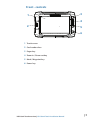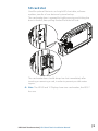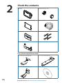
1
HDS Gen2 Touch
Installation Manual
ENGLISH
lowrance.com
Preface
As Navico is continuously improving this product, we retain the
right to make changes to the product at any time which may
not be reflected in this version of the manual. Please contact
your nearest distributor if you require any further assistance.
It is the owner’s sole responsibility to install and use the
instrument and transducers in a manner that will not cause
accidents, personal injury or property damage. The user of
this product is solely responsible for observing safe boating
practices.
NAVICO HOLDING AS AND ITS SUBSIDIARIES, BRANCHES AND
AFFILIATES DISCLAIM ALL LIABILITY FOR ANY USE OF THIS
PRODUCT IN A WAY THAT MAY CAUSE ACCIDENTS, DAMAGE OR
THAT MAY VIOLATE THE LAW.
Governing Language: This statement, any instruction manuals,
user guides and other information relating to the product
(Documentation) may be translated to, or has been translated
from, another language (Translation). In the event of any
conflict between any Translation of the Documentation, the
English language version of the Documentation will be the
official version of the Documentation. This manual represents
the product as at the time of printing. Navico Holding AS and
its subsidiaries, branches and affiliates reserve the right to make
changes to specifications without notice.
Copyright
Copyright © 2012 Navico Holding AS.
Warranty
The warranty card is supplied as a separate document.
In case of any queries, refer to the brand web site of your
display or system:
www.lowrance.com
Declarations and conformance
This equipment is intended for use in international waters as
well as inland waters and coastal sea areas administered by
countries of the USA, E.U. and E.E.A.
|1
Compliance Statements
Lowrance HDS-7, HDS-9, and HDS-12 Gen2 Touch:
• meet the technical standards in accordance with Part 15.103 of
the FCC rules
• comply with CE under RTTE directive 1999/5/EC
• comply with the requirements of level 2 devices of the
Radiocommunications (Electromagnetic Compatibility)
standard 2008
For more information please refer to our website:
www.lowrance.com
Warning
The user is cautioned that any changes or modifications not
expressly approved by the party responsible for compliance
could void the user’s authority to operate the equipment.
This equipment has been tested and found to comply
with the limits for a Class B digital device, pursuant to Part
15 of the FCC rules. These limits are designed to provide
reasonable protection against harmful interference in a
residential installation. This equipment generates, uses and
can radiate radio frequency energy and, if not installed and
used in accordance with the instructions, may cause harmful
interference to radio communications. However, there is no
guarantee that the interference will not occur in a particular
installation. If this equipment does cause harmful interference
to radio or television reception, which can be determined by
turning the equipment off and on, the user is encouraged to
try to correct the interference by one or more of the following
measures:
• Reorient or relocate the receiving antenna
• Increase the separation between the equipment and receiver
• Connect the equipment into an outlet on a circuit different
from that of the receiver
• Consult the dealer or an experienced technician for help
2|
About this manual
This manual is a reference guide for installing the Lowrance
HDS-7, HDS-9, and HDS-12 Gen2 Touch system.
The manual does not cover basic background information
about how equipment such as radars, echo sounders and AIS
work. Such information is available from our web site:
http://www.lowrance.com/Support/Library/
Important text that requires special attention from the reader is
emphasized as follows:
¼¼ Note: Used to draw the reader’s attention to a comment or
some important information.
! Warning: Used when it is necessary to warn personnel
that they should proceed carefully to prevent risk of injury
and/or damage to equipment/personnel.
Trademarks
• ‘NMEA 2000’ is a registered trademark of the National Marine
Electronics Association
• ‘Navionics’ is a registered trademark of Navionics SpA
• ‘Simrad’ is a trademark of Kongsberg Maritime AS Company
registered in the US and other countries and is being used
under license.
• ‘HDS’, ‘StructureScan’, ‘Navico’, ‘Lowrance’, ‘SonicHub’, ‘SimNet’
and ‘Skimmer’ are trademarks of Navico, registered in the
US and other countries. ‘InsightHD’, ‘Broadband Radar’ and
‘Broadband Sonar’ are trademarks of Navico.
|3
Contents
6
HDS Gen2 Touch overview
7
8
9
Front - controls
Rear - connectors
SD card slot
10
Check the contents
11
Display Installation
11
Mounting location
12 Bracket mounting
13 Flush mounting
14Research
14 Select a transducer location
15 Attaching the transducer
16 Adjusting the transducer
17Wiring
17Guidelines
18 Power connection
20 Transducer connection
21 Ethernet device connection
22 NMEA 2000 device connection
24 NMEA 0183 device connection
25 Video In
25 Connecting video sources
4|
26
Software setup
26
28
28
Sonar installation settings
Touch Screen Calibration
Software upgrades
29
Dimensional drawings
29
29
29
HDS 7 Gen2 Touch
HDS 9 Gen2 Touch
HDS 12 Gen2 Touch
30Accessories
30 NMEA 2000
30Transducers
31 Ethernet cables
31 Display parts
33
Supported data
33
34
NMEA 2000
NMEA 0183
35Specifications
|5
1
6|
HDS Gen2 Touch overview
The HDS-7, HDS-9, and HDS-12 Gen2 Touch multifunction displays
are available with or without inbuilt sonar and structure scan. The
ability to network over NMEA 2000 and ethernet allows access
to data as well as control of numerous optional devices that can
provide sonar, radar, audio entertainment, weather and even digital
switching.
All displays are charting ready, with built-in GPS receiver and Insight
cartography (region dependent) and with optional Navionics
support via an SD card slot.
The displays may be mounted on to the vessel with the supplied
surface mount bracket, or flush mounted in to the dash.
Power should be supplied at around 12V, but due to the variable
nature of boat power systems, the displays are designed to operate
on 10.8 V - 17 V.
HDS Gen2 Touch overview | HDS Gen2 Touch Installation Manual
Front - controls
1
3
4
2
5
6
1 Touchscreen
2 Card reader door
3 Pages key
4 Zoom in / Zoom out key
5 Mark / Waypoint key
6 Power key
HDS Gen2 Touch overview | HDS Gen2 Touch Installation Manual
|7
Rear - connectors
B
A
1
2
3
4
4
5
4
5
1
2
A HDS-9 & 12 connector arrangement
B HDS-7 connector arrangement
1 Sonar
2 StructureScan - connects to LSS-2 HD Transducer
3 Power - also video for HDS-9 & 12, with optional adaptor
4 Ethernet - two ports on HDS-9 & 12, one on 7
5 NMEA 2000
8|
HDS Gen2 Touch overview | HDS Gen2 Touch Installation Manual
3
SD card slot
Used for optional Navionics or InsightHD chart data, software
updates, transfer of user data and system backup.
The card reader door is opened by lightly pressing and sliding the
door to the left, then pulling forward from the left side.
The card reader door should always be shut immediately after
inserting or removing a card, in order to prevent possible water
ingress.
¼¼ Note: The HDS-9 and 12 Displays have two card readers, the HDS-7
has one.
HDS Gen2 Touch overview | HDS Gen2 Touch Installation Manual
|9
2
Check the contents
Display
Bracket knobs (x2)
Front Bezel (attached to unit)
Power cable
Sun cover
Fasteners - #6 x 1.5” (4x)
Mounting bracket
Parts Included, dependent on model
10 |
83/200 KHz transducer
LSS-2 HD transducer
50/200 KHz transducer
DVD - manuals
Check the contents | HDS Gen2 Touch Installation Manual
3
Display Installation
Mounting location
Choose the mounting locations carefully before you drill or cut.
The display should be mounted so that the operator can easily use
the controls and clearly see the display screen. Be sure to leave a
direct path for all of the cables. Lowrance displays are high-contrast
and anti-reflective, and are viewable in direct sunlight, but for best
results install the display out of direct sunlight. The chosen location
should have minimal glare from windows or bright objects.
Ensure that any holes cut are in a safe position and will not weaken
the boat’s structure. If in doubt, consult a qualified boat builder.
Before cutting a hole in a panel, make sure that there are no hidden
electrical wires or other parts behind the panel.
Do not mount any part where it can be used as a hand hold, where
it might be submerged, or where it will interfere with the operation,
launching or retrieving of the boat.
If bracket mounting the display, choose an area where the display
will not be subjected to excessive vibration.
The mounting location will affect the internal GPS receiver. Test the
unit in it’s intended location to ensure satisfactory reception. An
external GPS source may be added to overcome poor reception
areas.
Leave sufficient clearance to connect all relevant cables.
Good ventilation is required. Inadequate ventilation may cause the
display to overheat. Lowrance displays are designed to operate in
temperatures from -15° C to +55° C (+5° F to +131° F).
For overall width and height requirements, please see the
dimensions section on page 29.
! Warning: When installing the displays, ensure appropriate
safety equipment is used, eg. ear muffs, protective glasses, gloves
and a dust mask.
Power tools may exceed safe noise levels, and can cast off
dangerous protectiles.
The dust from many materials commonly used in boat
construction may cause irritation or damage to eyes, skin, and
lungs.
Display Installation | HDS Gen2 Touch Installation Manual
| 11
Bracket mounting
Place the bracket in the desired mounting location, and use a pencil
or permanent marker to mark drilling locations.
¼¼ Note: ensure that the chosen location has enough height to
accomodate the display fitted in the bracket, and allows tilting of
the display. Also adequate space is required on both sides to allow
tightening and loosening of the knobs.
Use fasteners suited to the mounting surface material. If the material
is too thin for self tappers, reinforce it, or mount bracket with
machine screws and large washers. Use only 304 or 316 stainless
steel fasteners. Mark the screw locations using bracket as template,
and drill pilot holes.
Screw down the bracket.
12 |
Mount the display to the bracket using the knobs. Hand tighten
only. The ratchet teeth in the bracket and display case ensure a
positive grip and prevent the unit changing from the desired angle.
Display Installation | HDS Gen2 Touch Installation Manual
Flush mounting
Check the template for scaling accuracy, using a tape measure or
ruler against the ruler printed on the template.
95.
3
mm
(7.
50"
)
MO
UNT
ING
SCR
EW
SIZ
E IS
110.2 mm (3.75")
#6
99.5 mm (3.92")
TAP
95.
PIN
G
3
C
L
SCR
EW
mm
(7.
50"
)
SU
PR
N
OD
UC
T
CO
VER
OU
TLI
C
L
NE
190
.5
mm
(7.
50"
)
199.0 mm (7.83")
220.4 mm (8.68")
Check dimensions before cutting
12"
Cut away excess paper, and tape down the template. Check it is
correctly aligned to a vertical or horizontal reference. Do not use a
bubble level as vessel may be listing! Adjust where required.
Drill all marked pilot holes, then using an appropriate saw, cut
through the template and mounting surface, along the dotted line
bordering the shaded center of the template.
Remove the bezel from the display, using a fingernail or small flat
screwdriver, starting at the edges that are closest to the card reader
door.
Check the fit of the display, and use a file to remove any remaining
obstructions. If water-tightness is required, apply a thin, continuous
bead of sealant to the back of the display prior to final installation.
Sealant should be of a ‘neutral cure’ type to prevent damage to
the plastics. Secure the display with the supplied screws. Once
screws are fully tightened, ensure there is complete contact with
the mounting surface. Lastly, fit the bezel with the card reader door
open; insert the outermost tabs on the bezel in to the slots on the
display, then gently press down the bezel above and below the card
reader door till it clicks in to place.
Display Installation | HDS Gen2 Touch Installation Manual
| 13
4
Mounting the transducer
Transducer location selection and installation are two of the
most critical steps in sonar installation. To function properly the
transducer must be in the water at all times, and in a location that
has a smooth flow of water when the boat is moving.
Research
Before starting the installation of the transducer, it’s advised to
check the following;
• Find out if the boat builder has a recommended installation location
• Establish direction of rotation of the propeller(s)
• Watch actual water flow when boat is travelling at cruising speed to
determine the area of transom with cleanest flow (least bubbles)
Select a transducer location
The primary aim is to stay clear of propeller and hull generated
turbulence, while mounting the transducer as close to the center of
the vessel as possible.
1
2 3
4
5
1 Avoid mounting within 1m (3.3’) to port of propeller
2 Conventional clockwise propeller rotation
3 Avoid mounting within 7.5cm (3“) to starboard of propeller
4 Best mounting location - undisturbed water flow
5 Planing strake - avoid mounting behind here
¼¼ Note: Reverse the distance guides (1 & 3) from propeller where
engine is of counterclockwise configuration.
14 |
Display Installation | HDS Gen2 Touch Installation Manual
¼¼ Note: Boats with strakes or ribs on the hull can create large amounts
of turbulence at higher speeds. A good transducer location on these
types of boats is between the ribs closest to the engine.
¼¼ Note: If the transducer is not placed in a smooth flow of water,
interference caused by bubbles and turbulence may show onscreen in the form of random lines or dots. The unit could also lose
bottom signal when the boat is on plane.
¼¼ Note: Trim tabs will vary in the amount of turbulence they create as
they are adjusted, stay clear of these.
Attaching the transducer
The transducer should be installed parallel with the transom’s
waterline, not the bottom of the boat (deadrise).
¼¼ Note: Ensure the entire bottom surface of the transducer hangs
at least couple of millimetres (1/16ths of an inch) lower than the
bottom of the hull.
Hold the transducer with bracket up to the transom of the boat
and trace the slotted screw hole locations (two on the 83/200 KHz
transducer, and four on the 50/200 KHz transducer). Mark drilling
points in the middle of each outline, to allow for transducer height
adjustment. Drill pilot holes to suit fasteners.
¼¼ Note: Check that there is nothing on the other side of the mounting
surface that may be damaged by drilling.
Attach transducer to transom, using supplied stainless steel
fasteners. Drill a 25mm (1”) hole above the waterline, large enough
to pass the plug through.
Display Installation | HDS Gen2 Touch Installation Manual
| 15
Secure the cable to the hull at regular intervals using cable P clips or
saddles and ensure that moving parts such as an outboard motor or
boarding ladder can’t snag the cable.
Adjusting the transducer
If the sounder image shows interference lines on the screen when
moving, which worsen with speed, it may be possible to eliminate
these by adjusting the transducer’s angle.
¼¼ Note: A transducer that is tilted too far in either direction will not
perform well, missing targets, and/or losing the bottom at speed.
If performance does not improve with tilting, try adjusting the
height of the transducer relative to the transom of the boat. If the
transducer is too high it may be seeing cavitation caused by the
trailing edge of the transom.
16 |
Display Installation | HDS Gen2 Touch Installation Manual
5
Wiring
Guidelines
Don’t do this
Do this
Don’t make sharp bends in the
cables
Don’t run cables in a way that
allows water to flow down into
the connectors
Don’t route the data cables
in areas adjacent to radar,
transmitter, or large current
carrying cables
Do make drip and service loops
Do cable tie all cables to keep
them secure
Do solder/crimp and insulate all
wiring connections, if extending
or shortening power or NMEA
0183 cables
Do leave room at the back to
install and remove cables
! Warning: Before starting the installation, be sure to turn
electrical power off. If power is left on or turned on during the
installation, fire, electrical shock, or other serious injury may occur.
Be sure that the voltage of the power supply is compatible with
the HDS Gen2 Touch display
! Warning: The HDS Gen2 Touch has a voltage rating of 12 V
DC, it is not suited for use with 24V DC systems.
! Warning: The positive supply wire (red) should always be
connected to (+) DC with the supplied fuse or a circuit breaker
(closest available to fuse rating).
Wiring | HDS Gen2 Touch Installation Manual
| 17
Power connection
HDS Gen2 Touch displays are designed to be powered by a 12 V DC
system. They are protected against reverse polarity, under voltage
and over voltage.
The plug of the supplied power cable has two discrete cables exiting
from it. The thickest cable provides the following:
• power into the system (Red and Black wires)
• remote turn-on for certain Navico expansion modules (Yellow wire)
4
1
2
3
6
5
_ +
1 HDS display rear (9 & 12 connector arrangement shown)
2 Power cable
3 12 V negative wire (black)
4 12 V positive wire (red) shown with fuse holder fitted
5 Accessory Wake Up wire (yellow)
6 Vessel’s 12 V DC supply
Connect red to (+) DC using a 5 A fuse. Connect Black to (-) DC.
Accessory wake up
The yellow colored accessory wake up line may be used to
control the power state of Navico modules such as SonicHub,
StructureScan, and Broadband radar. This means that the modules
are turned on the moment the display is powered up.
¼¼ Note: Broadband radar will be put in standby, when triggered by the
accessory wake up line.
For connection, simply combine all yellow wires on a common bus
or to a single termination point.
18 |
Wiring | HDS Gen2 Touch Installation Manual
The following demonstrates the power connections for a small
system.
1
2
3
4
5
6
7
+ _
8
1 HDS Displays
2 HDS power cable
3 Broadband radar interface
4 SonicHub
5 12 V DC negative (-)
6 12 V DC postive (+)
7 Accessory wake up line
8 Vessel’s 12 V DC supply
Wiring | HDS Gen2 Touch Installation Manual
| 19
Transducer connection
All Combo HDS Gen2 Touch displays have internal Broadband and
StructureScan sonar (chart only units require an external module
for sonar). Navico transducers fitted with the 7 pin blue connector
can be plugged directly into the corresponding blue socket labeled
‘Sonar’. The 9 pin black structure scan connector can be plugged
in to the socket labelled ‘Structure’ . Refer to the Overview section
of this manual, or embossed labeling on the unit for connector
location.
Connector attached to cable is keyed and can only be inserted in
one orientation. Once inserted, turn locking collar to secure.
¼¼ Note: Connectors are not in same location on the HDS-7 display as
they are on the HDS-9 and 12 displays (shown above). The ‘Structure’
connector is located to the right of the ‘Sonar’ connector on all units.
¼¼ Note: Sonar data can also be supplied by an external sonar
source such as the BSM-2 or another sonar capable Navico display
connected via ethernet.
¼¼ Note: While made for LSS-2 HD transducer, the displays are also
compatible with earlier LSS-1 transducers through use of an adaptor
cable - see page 30.
20 |
Wiring | HDS Gen2 Touch Installation Manual
Ethernet device connection
Ethernet is used to interconnect high bandwidth devices such as
radar, sonar, and other displays. The HDS-7 display has one ethernet
port, whereas the HDS-9 and 12 displays have two. Navico ethernet
cables have a locking collar, for maintaining a reliable, waterproof
connection.
Connecting directly to a single device
The ethernet port is auto sensing, meaning that the unit can
connect to one network device directly, without the use of a crossover cable or switch.
Connecting to multiple devices
If connecting more than one ethernet device to a HDS-7 display, or
two devices to a HDS-9 or HDS-12 display, use the optional network
expansion Port (NEP-2).
If the number of ethernet devices exceeds the number of available
ports on the NEP-2, it is possible to link two or more NEP-2 modules
together to provide the required ports. The NEP-2 modules are fitted
with 5 ethernet ports. See page 31 for cable options.
¼¼ Note: When designing a system, take in to account the ports ‘lost’
when used for linking multiple NEP-2 modules together.
Wiring | HDS Gen2 Touch Installation Manual
| 21
NMEA 2000 device connection
All HDS Gen2 Touch models are equiped with a NMEA 2000 port,
which allows the receiving and sharing of a multitude of data from
various sources.
Essential network information
• A NMEA 2000 network consists of a linear “backbone” from which
“drop cables” connect to NMEA 2000 devices
• NMEA 2000 is a powered network.
• NMEA 2000 cables used for Lowrance products are of the ‘micro-c’
style, which is a cable/connector specification approved for use in
NMEA 2000 certified networks.
• A single drop cable has a maximum length of 6 m (20 ft). The total
length of all drop cables combined should not exceed 78m (256 ft)
• The backbone has a maximum cable length of 100m (328ft). The
maximum cable length between any two devices on the network
is also 100 m (328 ft) - this is taking in to account device drop cable
length.
• A NMEA 2000 network needs to have a terminator at each end of
the backbone.
Planning and installing a network backbone
The NMEA 2000 backbone needs to run between the locations of all
products you want to install, typically in a bow to stern layout. Route
the backbone so that drop cables to devices do not exceed 6m
length. Choose from the following components to make up your
NMEA 2000 backbone:
• Micro-C cables: 2’ (0.61m), 6’ (1.82m), 15’ (4.55m), 25’ (7.58m)
• T-connector. Use at locations where you want to connect a device
by drop cable
• Micro-C male and Micro-C female to SimNet adaptor cables for
connecting to SimNet bus, or adding devices fitted with a SimNet
connector to a Micro-C network.
¼¼ Note: If using a wind sensor, plan to connect this to one end of the
backbone with the termination resistor at the mast head.
Power the network
A NMEA 2000 network requires its own 12 V DC power supply. The
Lowrance NMEA 2000 power cable is pre fitted with an inline fuse
holder and 3 amp fuse.
22 |
Wiring | HDS Gen2 Touch Installation Manual
In smaller NMEA 2000 systems, the power connection may be made
anywhere in the system,
For larger systems introduce power at a central point in the
backbone to ‘balance’ the voltage drop of the network. Use a power
cable without termination.
¼¼ Note: When joining a NMEA 2000 network with a Simrad SimNet
network, it is important that you do not introduce power to both.
¼¼ Note: Do not connect the power cable to the same terminals as the
autopilot computer, pulse radar, bow thruster or other high current
devices - the network may be affected by voltage drop when these
devices are operated. Avoid connection to the engine starting
batteries where possible.
The following diagram demonstrates a typical small NMEA 2000
network:
1
3
2
4
5
_
+
12 V DC
T
6
9
T
7
8
9
1 GPS antenna
2 HDS Display
3 Broadband radar interface
4 SonicHub
5 ‘Drop’ cables (should not exceed 6m (20’) each)
6 Power cable
7 Micro-C T junctions
8 Backbone
9 Micro-C terminator (one male, one female)
Wiring | HDS Gen2 Touch Installation Manual
| 23
NMEA 0183 device connection
The HDS has a NMEA 0183 serial port, providing both an input and
output for NMEA 0183 data.
The port can be set to different baud rates, up to 115,200 baud. The
NMEA0183 sentences output can be individually turned on or off.
Refer to the section Supported Data / NMEA 0183 for a complete list
of sentences.
1
2
3
4
1 Data cable (combined in same plug as power cable)
2 Transmit: A (yellow), B (blue)
3 Receive: A (orange), B (green)
4 ground (shield)
¼¼ Note: The majority of NMEA 0183 devices communicate at 4,800
baud. AIS is a common exception, and normally transmits at 38,400
baud.
24 |
Wiring | HDS Gen2 Touch Installation Manual
Talkers and Listeners
Do not connect multiple devices outputing data (Talkers) on to
the input (Rx) of the unit. The RS422 protocol is not intended for
this type of connection, and data will be corrupted if more than
one device transmits simultaneously. The output however may
drive multiple receivers (Listeners). The number of receivers is finite,
and depends on the receiving hardware. Typically three devices is
possible.
Video In
On the HDS-9 and HDS-12, a video camera may be added by
installing the optional video adaptor cable between the power
socket on the unit, and the plug on the power/data cable.
¼¼ Note: The video images will not be shared with another unit via the
network. It is only possible to view video on the unit connected to
the video source.
Connecting video sources
12 V DC
1
2
3
4
1 Video input adaptor cable
2 RCA plug
3 12 V camera (3rd party)
4 HDS power/data cable
¼¼ Note: Only connect NTSC and PAL video sources
Wiring | HDS Gen2 Touch Installation Manual
| 25
6
Software setup
Sonar installation settings
Keel offset
This is a value that can be entered on the Sonar Installation page to
make depth readings relate to any point from the water surface, to
the deepest point of the vessel.
Below are some typical ways in which the offset is used:
A) For Depth below Keel: Set the distance from transducer to the
keel.
Enter a negative value, e.g.
B) For Depth Below Transducer: no offset required.
C) For Depth Below Surface (waterline): Set the distance from
transducer to the surface:
Enter a positive value., e.g.
A
26 |
B
Software setup | HDS Gen2 Touch Installation Manual
C
Water speed calibration
Water speed calibration is used to adjust the speed value from the
paddle wheel to match the actual boat speed through the water.
Actual speed can be determined from GPS speed over ground
(SOG) or by timing the boat over a known distance. Water speed
calibration should be performed in calm conditions, with minimal
wind and current movement.
Water speed averaging
Averages water speed by measuring your speed at a selected
interval of time. Water speed intervals range from one to thirty
seconds, e.g. If you select five seconds, your displayed water speed
will be based on averaging over 5 seconds of sampling.
Water temperature calibration
Temperature calibration is used to adjust the water temperature
value from the sonar transducer to match the data from another
temperature sensor. It may be required to correct for localized
influences to the measured temperature.
¼¼ Note: Water temperature calibration only appears if the transducer is
temperature capable. Check transducer type selection if this option
should be available.
Transducer type
Transducer type is used for selecting the transducer model that
came with your unit. In some transducers with built-in temperature
sensors, the temperature reading may be inaccurate if the wrong
transducer is selected from the transducer type menu.
Software setup | HDS Gen2 Touch Installation Manual
| 27
Touch Screen Calibration
In some cases it may be required to re-calibrate the touch screen
due to electrical influences on the device from it’s installation
environment. The following steps should be completed to apply
calibration:
1. Turn the unit off
2. Press and hold the Waypoint key, then turn the unit on
3. Hold the Waypoint key during power on, until the calibration utility screen
comes up
4. Touch crosshair
shown on screen to perform nine points calibration
5. After successful calibration the unit will return to normal application screen
Software upgrades
The latest software for this unit will be available for download from
the Lowrance web site;
www.lowrance.com
An SD card and SD reader/writer are required for this.
Detailed instructions for how to install the software are provided on
the update web page.
28 |
Software setup | HDS Gen2 Touch Installation Manual
HDS 7 Gen2 Touch
82 mm (3.23")
215 mm (8.48")
7"
166 mm (6.52")
146 mm (5.76")
30 mm (1.18")
240 mm (9.45")
95 mm (3.72")
HDS 9 Gen2 Touch
178 mm (7.01")
9"
169 mm (6.65")
30 mm (1.18")
54 mm (2.13")
265 mm (10.43")
287 mm (11.30")
60.5 mm (2.38")
HDS 12 Gen2 Touch
30.3 mm (1.19")
328.1 mm (12.92")
.1
"
233.6 mm (9.20")
12
60.9 mm (2.4")
224.7 mm (8.85")
7
Dimensional drawings
351.0 mm (13.82")
62 mm (2.44")
82.8 mm (3.26")
Dimensional drawings | HDS Gen2 Touch Installation Manual
| 29
8
Accessories
Refer to website for latest accessories: www.lowrance.com
NMEA 2000
Part number
000-0124-69
000-0119-88
000-0127-53
000-0119-86
000-0119-83
000-0120-39
000-0120-41
000-0120-49
000-0120-51
000-0120-53
000-0120-73
000-0120-29
000-0125-28
22090195
Description
NMEA 2000 STARTER KIT
N2KEXT-2RD 2’ (0.61M) EXTENSION CABLE
N2KEXT-6RD 6’ (1.82M) EXTENSION CABLE
N2KEXT-15RD 15’ (4.55M) EXTENSION CABLE
N2KEXT-25RD 25’ (7.58M) EXTENSION CABLE
EP-60R FUEL FLOW SENSOR
EP-65R FLUID LEVEL SENSOR
EP-70R PADDLE WHEEL SPEED SENSOR
EP-80R TEMPERATURE SENSOR
EP-80RTH THRU-HULL TEMPERATURE SENSOR
EP-85R STORAGE DEVICE
EP-90R PRESSURE SENSOR
LGC-4000 HIGH SPEED GPS RECEIVER
RC42 RATE COMPASS
Transducers
Part number
000-0106-72
000-0106-74
000-0106-89
000-0106-77
000-0106-94
000-0099-95
000-0099-96
000-0099-97
000-0099-93
000-0099-94
000-10802001
30 |
Description
HST-WSBL 83/200 TRANSOM SKIMMER WITH
TEMP
PDT-WBL 83/200 POD WITH TEMP
PDRT-WBL 83/200 POD WITH REMOTE TEMP
HST-DFSBL 50/200 TRANSOM SKIMMER WITH
TEMP
PTI-WBL ICE TRANSDUCER
TS-1BL EXTERNAL TEMP SENSOR (NON-NMEA
2000)
SP-BL TRANSOM SPEED WHEEL (NON-NMEA 2000)
ST-TBL TRANSOM SPEED/TEMP (NON-NMEA 2000)
XT-12BL 12FT BLUE CONNECTOR TRANSDUCER
EXTENSION
XT-20BL 20FT BLUE CONNECTOR TRANSDUCER
EXTENSION
LSS-2 HDS SKIMMER 20 FT STRUCTURESCAN HD
SKIMMR XDCR LSS-2
Accessories | HDS Gen2 Touch Installation Manual
Part number
000-0136-02
000-0136-03
000-10116-001
000-00021-001
000-0136-05
Description
P319 50/200 LOW PROFILE THRU-HULL W/TEMP
P79 50/200 IN-HULL
TM260 50/200 TRANSOM MOUNT W/TEMP
B60 50/200 BRONZE THRU-HULL W/TEMP
B744V 50/200 BRONZE THRU-HULL W/TEMP AND
SPEED
000-10247-001
000-0136-00
000-0106-82
000-0106-91
22098479
B164 50/200 BRONZE THRU-HULL W/TEMP 1KW
B258 50/200 Bronze Thru-Hull w/Temp
B260 50/200 Bronze Thru-Hull w/Temp
M260 50/200 Tank Mounted In-Hull
DST-800 235 NMEA 2000 Smart Sensor w/
Temp and Speed (Digital display only, no
sonar image)
000-11040-001 LSS-1 XDCR TO LSS-2 MODULE ADAPTOR
Ethernet cables
Part Number
000-0127-56
000-0127-51
000-0127-29
000-0127-30
000-0127-37
Description
Adapter cable: Ethernet Yellow Male to
RJ-45 female 2m (6.5ft)
Ethernet cable yellow 5 Pin 2m (6.5ft)
Ethernet cable yellow 5 Pin 4.5m (15ft)
Ethernet cable yellow 5 Pin 7.7m (25ft)
Ethernet cable yellow 5 Pin 15.2m (50ft)
Display parts
Part Number
000-11010-001
000-11033-001
000-11034-001
000-11035-001
000-11030-001
000-11031-001
000-11032-001
000-11019-001
000-11020-001
000-11021-001
000-11050-001
000-10467-001
Description
HDS GEN2 VIDEO ADAPTER CABLE
HDS-7 GEN2 TOUCH BEZEL AND CARD DOOR
HDS-9 GEN2 TOUCH BEZEL AND CARD DOOR
HDS-12 GEN2 TOUCH BEZEL AND CARD DOOR
HDS-7 GEN2 TOUCH SUNCOVER
HDS-9 GEN2 TOUCH SUNCOVER
HDS-12 GEN2 TOUCH SUNCOVER
HDS-7 GEN2 TOUCH GIMBAL BRACKET
HDS-9 GEN2 TOUCH GIMBAL BRACKET
HDS-12 GEN2 TOUCH GIMBAL BRACKET
HDS GEN2 TOUCH FLUSH MOUNT KIT
BRACKET KNOBS PAIR – NSS/GEN2T
Accessories | HDS Gen2 Touch Installation Manual
| 31
Part Number
000-0127-49
000-0124-70
000-0127-50
32 |
Description
HDS Power Cable
HDS Connector Caps
HDS Fuse & Fuse Holder
Accessories | HDS Gen2 Touch Installation Manual
9
Supported data
NMEA 2000
PGN
59392
60928
126208
126992
126996
127237
127245
127250
127251
127257
127258
127488
127489
127493
127503
127505
127506
127508
128259
128267
129808
129025
129026
129029
129033
129038
129039
129040
129283
129284
Description
ISO Acknowledgement
Address Claim
NMEA Group Function
System Time
Product Info
Heading/Track Control
Rudder
Vessel Heading
Rate of Turn
Attitude
Magnetic Variation
Engine Parameters Rapid Update
Engine Parameters Dynamic
Transmission Parameters Dynamic
AC Input Status
Fluid Level
DC Detailed Status
Battery Status
Speed Water Referenced
Water Depth
DSC Call Information
Position Rapid Update
COG & SOG, Rapid Update
GNSS Position Data
Time and Date
AIS Class A Position Report
AIS Class B Position Report
AIS Class B Extended Position Report
Cross Track Error
Navigation Data
Rx
1
1
1
1
1
1
1
1
1
1
1
1
1
1
1
1
1
1
1
1
1
1
1
1
1
1
1
1
1
1
129285
129539
129540
129794
129801
129802
129808
Route/WP Information
GNSS DOPs
GNSS Sats In View
AIS Class A Static and Voyage Related Data
AIS Addressed Safety Related Message
AIS Safety Related Broadcast Message
DSC Call Information
1
1
1
1
1
1
Supported data | HDS Gen2 Touch Installation Manual
Tx
1
1
1
1
1
1
1
1
1
1
1
1
1
1
1
1
1
1
| 33
PGN
Description
Rx Tx
130074
130306
130310
130311
130312
130313
130314
130576
130577
Waypoint Name and Position
Wind Data
Environmental Parameters
Environmental Parameters
Temperature
Humidity
Actual Pressure
Small Craft Status
Direction Data
1
1
1
1
1
1
1
1
1
1
1
1
1
1
NMEA 0183
TX / RX Category / Sentence
GPS
Receive GGA GLL GSA
Transmit GGA GLL GSA
Navigation
Receive RMC
Transmit AAM APB BOD
Echo
Receive DBT DPT MTW
Transmit DBT DPT MTW
Compass
Receive HDG HDT HDM
Transmit HDG
Wind
Receive MWV MWD
Transmit MWV
AIS / DSC
Receive DSC
MARPA
Transmit TLL
DSE
GSV VTG
GSV VTG
ZDA
ZDA
BWC BWR RMC
RMB
VLW VHW
VLW VHW
VDM
TTM
¼¼ Note: AIS sentences are not bridged to or from SimNet.
34 |
Supported data | HDS Gen2 Touch Installation Manual
XTE
SD (full size)
Specifications | HDS Gen2 Touch Installation Manual
30.5 x 27.9 x 27.9 cm (12" x 11" x 11")
2.54 kg (5.6 lb)
Pack dimensions (L x W x H)
Pack weight
(50/200 or 83/200 kHz) + 455/800 kHz
Max power 500W RMS
Sonar frequency
Sonar output power
Echo sounder
1.6 kg (3.5 lb)
Weight (display only)
Other
No
Data card slot
1 Port
Video input
NMEA2000
Ethernet
Interface
Declaration of conformity
Waterproof standard
Temperature
Housing
IPx7
-15° C to + 55° C (+5° F to +131° F)
Plastic
15.6 W (1.2 A @ 13 V DC)
12 V DC (10.8 - 17.0 V DC min - max)
S-CAP
1400 nits
9 inch WVGA color TFT LCD
800x480
HDS-9
Max power 500W RMS
(50/200 or 83/200 kHz) + 455/800 kHz
2.9 kg (6.5 lb)
2 Ports
26 W (2.0 A @ 13 V DC)
12 V DC (10.8 - 17.0 V DC min - max)
1250 nits
12.1 inch WXGA TFT LCD
1280x800
HDS-12
Max power 500W RMS
(50/200 or 83/200 kHz) + 455/800 kHz
3.78 kg (8.3 lb)
2x SD (full size)
Composite video RCA - single channel
Micro-C (1)
40.6 x 27.9 x 25.4 cm (16" x 11" x 10")
2.1 kg (4.6 lb)
2x SD (full size)
2 Port
Part 15.103 FCC rules & CE RTTE directive 1999/5/EC
12 W (0.9 A @ 13 V DC)
Power consumption
Technical / Environmental
12 V DC (10.8 - 17.0 V DC min - max)
1250 nits
7 inch WVGA color TFT LCD
HDS-7
Power supply
Power
Touch screen
Display brightness
Display type
Display resolution
Display
Multi Function Display
10
Specifications
Refer to website for updates to specifications: www.lowrance.com
| 35
N2584
*988-10317-002*