1
CAUTION:
o
o
o
o
o
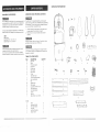
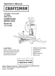
Before using this band saw,
read this manual and follow
all its Safety Rules and
Operating Instructions.
Customer
Help
Safety Instructions
nnstallation
Operation
Maintenance
Parts List
Line
t °80@°843°1682
Sears,
Roebuck
Part No. 137224!40001
and Co., Hoffman
Estates,
BL 60179
USA
PAGE
SECTION
Warranty
................................................................
Product Specifications
.....................................................
Safety Instructicms
........................................................
Accessories
and Attachments
...............................................
Carton Contents
..........................................................
Know Your Band Saw ......................................................
Glossary
of Terms
........................................................
Assembly
and Adjustments
................................................
Operation
..............................................................
Maintenance
............................................................
Troubleshooting
guide ....................................................
Parts ..................................................................
2
2
3
6
6
8
9
10
19
21
22
24
DUST COLLECTION
MOTOR
Power source ......
Horsepower
.......
Speed ............
Type .............
t20 V AC, 60 HZ, 10 AMPS
1.5 HP (Max. Developed)
2700 Feet per minute (No load)
Induction
DRIVE BELT ..........
A 40
CUTTING CAPACITY
Throat ............
Height ............
13-5/8"
6"
BLADE
Width ............
Length
...........
1/8", 1/4", 3/8", 1/2"
91 -t/2" to 93-1/2"
TABLE
Size .............
Tilt ..............
14" x 14"
0 - 15° Left, 0 - 450 Right
NET WEIGHT
.........
...
BEFORE
Some dust created by power sanding sawing, grinding, drilling, and other construction activities contains chemicals
known [to the State of California] to cause cancer, birth defects or other reproductive harm. Some examples of these
chemicals are:
® Lead from lead-based paints.
® Crystalline silica from bricks and cement and other masonry products, and
Q Arsenic and chromium from chemically4reated lumber.
Your risk from these exposures varies, depending on how often you do this type of work. To reduce your exposure to
these chemicals: work in a welt ventilated area, and work with approved safety equipment, such as those dust masks
SAW
12.
To avoid mistakes that could cause serious injury, do not
plug the band saw in until you have read and understood
the following:
!.
READ and become familiar with this entire instruction
manual. LEARN the tool's applications, limitations,
and possible hazards.
2,
KEEP GUARDS mNPLACE and in working order.
REMOVE ADJUSTING KEYS AND WRENCHES.
Form the habit of checking to see that keys and
adjusting wrenches are removed from the tool before
turning ON.
194 LBS.
Your band saw is wired at the factory for t20V operation.
Connect to a 120V, 15 AMP branch circuit and use a 15
AMP time delay fuse or circuit breaker. To avoid shock or
fire, replace power cord immediately if it is worn, cut or
damaged in any way.
USING THE BAND
Safety is a combination of common sense, staying alert
and knowing how to use your band saw.
Yes
To avoid electrical hazards, fire hazards, or damage to
the toot, use proper circuit protection. Use a separate
electrical circuit for your tools,
11. WEAR PROPER APPAREL. DO NOT wear loose
clothing, gloves, neckties, rings, bracelets, or other
jewelry which may get caught in moving parts.
Non-slip footwear is recommended. Wear protective
hair covering to contain long hair.
GENERAL SAFETY _NSTRUCTIONS
4.
KEEP WORK AREA CLEAN. Cluttered areas and
benches invite accidents.
5.
DON'T USE iN A DANGEROUS ENVIRONMENT.
Don't use power tools in damp or wet locations, or
expose them to rain. Keep work area well lighted.
6,
KEEP CHILDREN AWAY. All visitors should be kept
at a safe distance from the work area.
7.
MAKE WORKSHOP KID-PROOF with padlocks,
master switches, or by removing starter keys.
8.
DON'T FORCE THE TOOL. It will do the job better
and safer at the rate for which it was designed.
9.
USE THE RIGHT TOOL. Don't force tool or the
attachment to do a job for which it was not designed.
ALWAYS WEAR EYE
PROTECTION. Any band saw
can throw foreign objects into
the eyes which could cause
permanent eye damage.
ALWAYS wear Safety Goggles
(not glasses) that comply with
ANSI safety standard Z87.1. Everyday eyeglasses
have only impact-resistant lenses. They ARE NOT
safety glasses. Safety Goggles are available at Sears.
NOTE: Glasses or goggles not in compliance with
ANSI Z87.1 could seriously hurt you when they break.
WEAR
YOUR
13. WEAR A FACE MASK OR DUST MASK. Sawing
operation produces dust.
14, SECURE WORK, Use clamps or a vise to hold work
when practical. It's safer than using your hand and it
frees both hands to operate tool.
15, DlSCONNECTTOOLS
before servicing, and when
changing accessories, such as blades, bits, cutters,
and the like.
16. REDUCE THE RISK OF UNINTENTIONAL
STARTING. Make sure the switch is in OFF position
before plugging in.
17. USE RECOMMENDED ACCESSORIES. Consult the
owner's manual for the recommended accessories.
The use of improper accessories may cause risk of
injury to persons.
18. NEVER STAND ON TOOL. Serious injury could occur
if the toot is tipped or if the cutting blade is unintentionally
contacted.
10, USE PROPER EXTENSION CORD. Make sure your
extension cord is in good condition. When using an
extension cord, be sure to use one heavy enough to
carry the current your product will draw.
An undersized cord will result in a drop in line voltage
and loss of power which will cause the tool to overheat,
The table on page 5 shows the correct size to use
depending on cord length and nameplate ampere
rating. If in doubt, use the next heavier gauge. The
smaller the gauge number, the heavier the cord.
19. CHECK FOR DAMAGED PARTS. Before further use
of the tool, a guard or other part that is damaged
should be carefully checked to determine that it wilt
operate properly and perform its intended function.
Check for alignment of moving parts, binding of moving
parts, breakage of parts, mounting, and any other
conditions that may affect its operation. A guard or
other part that is damaged should be properly repaired
or replaced.
that are specially designed to filter out microscopic particles.
SAVE THESE iNSTRUCTIONS
2
3
20. NEVERLEAVE TOOL
RUNNING UNATTENDED.
TURN THE POWER OFF. Don't leave the tool until it
comes to a complete stop.
21. DON'T OVERREACH.
balance at all times.
Keep proper footing and
22. MAINTAIN TOOLS WITH CARE. Keep tools sharp
and clean for best and safest performance. Follow
instructions for lubricating and changing acoessories.
23. DO NOT use power tools in the presence of
flammable liquids or gases.
24. DO NOT operate the toot if you are under the
influence of any drugs, alcohol or medication that
could affect your ability to use the tool properly.
25. Dust generated from certain materials can be
hazardous to your health. Always operate the band
saw in a well-ventilated area and provide for proper
dust removal. Use dust collection systems whenever
possible.
SPECiFiC SAFETY INSTRUCTaONS
.
2.
TO AVOID INJURY from unexpected movement, make
sure the saw is on a firm, level surface, properly
secured to prevent rocking. Make sure there is
adequate space for operating. Bolt the saw to a support
surface to prevent it from slipping, walking, or sliding
during operation.
TURN the saw OFF and unplug the saw before
moving it.
3.
USE THE CORRECT size and style of blade.
4.
USE blades rated at 2700 FPM or greater.
5.
MAKE SURE the blade teeth point down and
towards the table.
6,
BLADE GUIDES, SUPPORT BEARINGS, AND
BLADE TENSION must be properly adjusted to avoid
accidental blade contact and to minimize blade
breakage. To maximize blade support, afways adjust
the upper blade guide and blade guard so that it is
1/8 inch above the workpiece.
7.
TABLE LOCK HANDLE should be tight.
8:
USE EXTRA CAUTION with large, very small or
awkward workpieces.
g_
1t. PLAN intricate and small work carefully to avoid
pinching the blade, Avoid awkward operation and
hand positions to prevent accidental contact with the
bJade.
USE EXTRA SUPPORTS to prevent workpieces
from sliding off the table top. Never use another person
in place of a table extension, or to provide additional
support for the workpiece,
10. WORKPIECES must be secured so they don't twisL
rock, or slip while being cut.
12. SMALL PIECES should be secured with jigs or
fixtures. Do not hand hold pieces that are so small
your fingers are under the blade guard.
13. SUPPORT round work properly (with a V-block or
clamped to the miter gauge) to prevent it from rolling
and the blade from biting.
14. CUT only one workpiece at a time. Make sure the
table is clear of everything except the workpiece and
its guides before you turn the saw on.
15. ALWAYS WATCH the saw run before each use. If
there is excessive vibration or unusual noise, stop
immediately. Turn the saw off. Unplug it immediately.
Do not start the saw again until the problem has
been located and corrected.
16. TO FREE any jammed material, turn the switch OFR
Remove the switch key and unplug the saw. Wait for
all moving parts to stop before removing jammed
material.
17. DON'T LEAVE the work area until all moving parts
are stopped. To childproof the workshop, shut off the
power to master switches and remove the switch key
from the band saw. Store it in a safe place, away
from children.
For your own safety, read the entire instruction manual
before operating the band saw.
1. Wear eye protection.
2. Do not wear gtoves, necktie, or loose clothing.
3. Make sure the saw is on a firm level surface and
properly secured.
4. USE ONLY THE RECOMMENDED ACCESSORIES.
5. Use extra caution with very large, very small, or
awkward workpieces.
6. Keep hands away from the blade at all times to
prevent accidental injury.
ELECTRnCAL
REQUBREMENTS
GROUNDING
GUIDEUNES
INSTRUCTIONS
tN THE EVENT OF A MALFUNCTION OR BREAKDOWN,
grounding provides a path of least resistance for electric
current and reduces the risk of electric shock. This tool is
equipped with an electric cord that has an equipment
grounding conductor and a grounding plug. The plug
MUST be plugged into a matching receptacle that is
properly installed and grounded in accordance with ALL
local codes and ordinances.
Be sure your extension cord is properly wired and in
good condition. Always replace a damaged extension cord
or have it repaired by a qualified person before using it.
Protect your extension cords from sharp objects, excessive
heat and damp or wet areas.
DO NOT MODIFY'THE PLUG PROVIDED. If it wilt not fit the
receptacle, have the proper receptacle installed by a
qualified electrician.
IMPROPER CONNECTION of the equipment grounding
conductor can result in risk of electric shock. The
conductor with the green insulation (with or without yellow
stripes) is the equipment grounding conductor. If repair or
replacement of the electric cord or plug is necessary, DO
NOT connect the equipment grounding conductor to a live
terminal.
(when using 120 volts only)
Ampere Rating
mo_e
CHECK with a qualified electrician or service person if you
do not completely understand the grounding instructions, or if
you are not sure the tool is properly grounded.
USE ONLY 3-wire extension cords that have 3-prong
grounding plugs and 3-pole receptacles that accept the
tool's plug. Repair or replace damaged or worn cord
immediately.
not
more
thaf_
6
18
16
16
6
10
18
16
14
12
10
12
16
16
14
12
12
16
14
12
Not recommended
CAUTION: In all cases, make certain the receptacle is
properly grounded, If you are not sure have a qualified
electrician check the receptacle.
Grounding Prong
Properly Grounded
3-Prong Receptacle
SAVE THESE mNSTRUCTIONS
(_-_ /
_L
_[_-_F_.-T-_ i
_',_,_-4_
j% 'f_-'_y_
_<-"_--
_"
Make
Sure This
is Connected to a
"_"t,_ Known Ground
_t_l _
_---.-
-
_N '_--._
Adapter
150'
14
0
Fig. 13 Grounding Lug _-_
To avoid electrical hazards, fire hazards, or damage to the
tool, use proper circuit protection. Use a separate electrical
circuit for your tools.Your saw is wired at the factory for
120V operation. Connect to a 120V, t5 Amp circuit and use
a 15 Amp time delay fuse or circuit breaker. To avoid shock or
fire, if power cord is worn or cut, or damaged in any way,
have it replaced immediately.
Totallength
of cord in feet
25'
50'
100'
This tool is intended for use on a circuit that has a
receptacle like the one illustrated in FIGURE A.
FIGURE A shows a 3-prong electrical plug and receptacle
that has a grounding conductor. If a properly grounded
receptacle is not available, an adapter (FIGURE B) can be
used to temporariIy connect this plug to a 2-contact
ungrounded receptacle. The temporary adapter shoutd be
used only until a properly grounded receptacle can be
installed by a qualified technician. The adapter (FIGURE B)
has a rigid lug extending from it that MUST be connected
to a permanent earth ground, such as a properly
grounded receptacle box. The Canadian Electrical Code
prohibits the use of adapters.
3-Prong Plug
POWER SUPPLY AND MOTOR SPECIFICATIONS
tha¢_
This band saw is for indoor use only. Do not expose to rain
or use in damp locations.
Use a separate electrical circuit for your tools. This circuit
must not be less than #12 wire and should be protected
with a 15 Amp time lag fuse. Before connecting the motor to
the power fine, make sure the switch is in the OFF
position and the electric current is rated the same as the
current stamped on the motor nameplate. Running at a
lower voltage will damage the motor.
I__
CORDS
USE PROPER EXTENSION CORD. Make sure your
extension cord is in good condition, When using an
extension cord, be sure to use one heavy enough to carry
the current your product will draw. An undersized cord will
result in a drop in line voltage and in loss of power which will
cause the tool to overheat. The table below shows the
correct size to use depending on cord length and
nameplate ampere rating. If in doubt, use the next heavier
gauge. The smaller the gauge number, the heavier the cord,
This tool must be grounded while in use to protect the
operator from electrical shock,
Fig. A
FOR EXTENSION
I]_" 2-Prong
Receptacle
SAVE THESE
iNSTRUCTiONS
5
UNPACKING YOUR BAND SAW
AVAILABLE
UNPACKING
ACCESSORIES
Do not attempt to modify this tool or create accessories
recommended
for use with this tool. Any such alteration
modification
is misuse and could result in a hazardous
condition leading to possible serious injury.
not
or
Visit your Sears Hardware Department or see the Sears
Power and Hand Toot Catalog for the following accessories:
ITEM
Miter gauge
Blade width:
AND CHECKgNG
CONTENTS
To avoid injury from unexpected starting, do not plug the
power cord into a power source receptacle during unpacking
and assembly. This cord must remain unplugged
whenever
you are assembting
or adjusting the saw.
!.
2,
Carefully unpack the band saw and all its parts, and
compare against the i!_ustration on page 7,
Place the saw on a secure surface and examine it
carefully.
D
B
1/8", 1/4", 3/8", 1/2"
Blade length: 91-1/2"
to 93-1/2"
Follow instructions
that accompany
accessories.
Use of
improper accessories
may cause hazards.
Do not use any accessory unless you have completely
read the instruction or owner's manual for that accessory.
Although compact,
get l_etp whenever
this saw is heavy. 3b avoid bank injury,
you have to lift the saw.
€
If any part is missing or damaged_ do not plug the band
saw in until the missing or damaged part is replaced, and
assembly is complete.
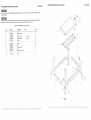
TABLE
iTEM
A
B
C
D
E
F
G
H
1
OF LOOSE
G
©
F
G
@
H
PARTS
DESCRIPTION
Band saw
Motor
Puller cover plate
Pulley belt
Pulley cover
Motor pulley
Motor collar
Pulley
"table with insert
QUANTITY
1
1
1
t
1
1
1
1
1
J
K
L
M
N
O
P
Q
R
Trunnion support bracket
Star handle knobs
Key
Sawdust port
Miter gauge
Long hex bolt with hex nut
Table aligning pin
Cord wrap bracket
Screws
1
2
2
1
1
I
1
2
2
S
T
Hex key
Bag of bolts, nuts, washers
1
!
cu_=o
O
P
i
Q
R
S
1
X
u
w
STAND:
U
V
W
Legs
Long leg brackets
Short leg brackets
X
Y
Z
Leg Pads
Leg stand top plate
Support plate
4
2
2
4
I
2
N
M
J
°....
° °
°
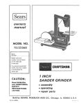
Upper
Upper blade wheel
cover
CRAFTSMAN
Lower blade
support bearing
BLADE GUIDES - Support the blade and keep it from
twisting during operation. Blade guides must be adjusted
when blade is changed or replaced.
Lowe
guide
Upper blade
support bearing
Upper blade guide
Blade
Wheel
switch
Table insert
Table
brush
Lower cover
Sawdust
lock knob
port
Upper guide
bar
MITER CUT - An angle cut made across the width of a
workpiece.
RESAW -A cutting operation to reduce the thickness of
the workpiece to make thinner workpieces.
UPPER GUIDE LOCK KNOB -,-locks the upper slide. Use it
after you adjust the upper guide assembly to make sure
upper blade guide just clears workpiece before cutting. Upper
guide lock knob must be tightened before the band saw is
turned on.
Blade guard
ON/OFF
LEADING EDGE - The end of the workpiece pushed into
the cutting tool first.
BAND SAW TERMS
RESgN - A sticky sap that has hardened.
RiPPiNG CUT - A cutting operation along the length of the
workpiece_
TABLE LOCK KNOB - locks the table in place.
Table removed for clarity
of illustration
TILT (BEVEL) SCALE -shows
tilted for bevel cutting.
1
Blade tension
knob
Blade tension
gauge
Biade tracking
knob
R.P.M. - Revolutions per minute. The number of turns
completed by a spinning object in one minute.
the degree the table is
SAW BLADE PATH -The area of the workpiece or table
top directly in line with the travel of the blade or the part of
the workpiece which will be cut.
BLADE TENSION KNOB - controls the amount of blade
tension when changing blades.
SET -The distance between two saw Made teeth tips, that
are bent outward in opposite directions to each other. The
further apart the tips are, the greater the set.
BLADETRACKING KNOB -adjusts blade position so blade
always runs in the center of the wheel.
SAWDUST PORT - helps keep the machine free from
sawdust_ The sawdust port makes an excellent hook-up for
a webJdry vacuum.
TRABUNG END - The workpiece end last cut by the blade.
Power cord wrap
WORKPIECE -The item being cut. The surfaces of a
workpiece are commonly referred to as faces, ends, edges.
ONIOFF SWITCH -has a built-in child safety lock. To lock
the switch in the OFF position, remove the switch key from
the switch.
Motor
Mounting holes
Blade guide
slide knob
Table
aligning pin
WOODWORKING
,cover
plate
Table tilt scale
Table trunnion
Motor cord
WORKTABLE -The surface on which the workpiece rests
while performing a cutting or sanding operation.
TERMS
BEVEL CUT - An angle cut made through the face of a
workpiece.
COMPOUND
Leading
CUT - A simultaneous bevel and miter cut.
Edge
Sawblade Path
Table tilt stop bolt
Kerr
CROSSCUT - A cut made across the width of the
workpiece,
Pulley cover
Surface
Miter gauge storage.
F.RM, - Feet per minute. Used in reference to the surface
speed of the saw blade.
I top
)late
Mounting
Stand
FREEHAND - Performing a cut without using a fence
(guide), hold-down or other proper device to prevent the
workpiece from twisting during the cutting operation.
Workpiece
Trailing Edge
GUM - A sticky sap-based residue from wood products.
HEEL - Misatignment of the blade.
KERF - The material removed by a blade in a through cut,
or the slot produced by the blade in a non-through or
partial cut.
8
:.
:
:.
:
::
::
:
:=:=:
:
,
9
:
,=:
= :
: :
:
=
:
=
ASSEMBLY
TOOLS
INSTRUCTIONS
NEEDED
Phillips screwdriver
Adjustable
wrench
Combination
Straight
square
edge
For your safety, never connect p4ug to power source
receptacle until all assembly and adjustment steps are
completed, and you have read and understood the safety
and operating instructions.
MOUNTING THE MOTOR (FIG. C)
3.
NOTE: The use of rubber grommets is essential for
eliminating excessive motor vibration,
4.
1.
5.
Although compabt, this saw is heavy. To avoid back injury,
get help to lift the saw.
2.
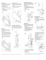
ASSEMBLE BAND SAWTO LEG STAND (FIG, B)
1. Lift the saw body (1) and ptace on the leg stand (2),
aligning with the four mounting holes.
2. Attach the band saw to the stand with four long t-3/8"
hex head bolts (3) and four flat washers (4),
3. Place fiat washers (4) and hex nuts (5) on the two rear
bolts, from the underside. Hand tighten.
4. Place the two
support plate (6) on the two front
bolts, under the stand as shown.
5. Fasten with a flat washer (4) and hex nut (5) on each
bolt. Hand tighten.
6. Tighten all bolts and nuts with a wrench.
3,
4,
Position the motor (1) as shown, aligning the mounting
holes.
Insert four !-3/8" long hex head bolts (2) with flat
washers (3) through the motor mounting holes, grommets,
and leg stand.
Place the two support pIate (4) on the bolts from
underneath the table, as shown.
Place fiat washers (3) and hex nuts (5) on the bolts. DO
NOT TIGHTEN.
Place the pulley cover plate (4) over the pulley shaft (2)
onto the flat surface of the collar.
Align the screw holes in the collar (1) and the pulley
cover plate (4).
Insert 3 Phillips head screws (5) and tighten. (Fig E)
Fig. E
Fig. C
Tf
TF --2
6.
7.
8,
LEG STAND ASSEMBLY (FIG. A)
1. Lay the top plate (1) upside down on a fiat surface.
2. Attach a leg (2) to the outside of the stand top plate
with two carriage bolts (3), washers (4), and nuts (5).
Do not tighten.
3. Repeat for the remaining three _egs.
4. Attach two tong brackets (6) and two short brackets (7)
to the inside of the legs using carriage bolts (3),
washers (4), and nuts (5), Do not tighten.
5. Place the leg pads (8) on each leg and turn the leg
stand upright on a firm level surface.
6, Tighten all bolts and nuts with a wrench.
Place the small motor pulley (6) onto the motor shaft (7).
Align the key tab (10) with the slot (9) on the shaft.
Tighten the hex socket screw (8) in the pulley. (Fig. F)
Fig. F
4
3
Fig. A
/
8
9.
Place the large pulley (11) on the band saw pulley
shaft (2).
10. Align the key tab (12) with the slot (13) on the shaft,
and tighten the hex socket screw (t4). (Fig. G)
6
ASSEMBLE THE PULLEY SYSTEM
7
Install the pulleys (FIG. D, E, F, G)
1, Place the motor collar (1) on the band saw pulley shaft
base (2), Align the holes in the collar and base,
2, Insert hex socket screws (3) in the collar and tighten.
(Fig, D)
Fig. G
Fig. D
5
10
1I
Align the pulleys (FIG. H)
1 !. Using a straight edge (13) placed in the grooves of
the two pulleys (6, 11), check the alignment of the
inside edges of the pulleys.
12. If the inside edges are not aligned:
a, Loosen the hex socket screws (8, 12) with a 3ram
hex wrench_
b. Adjust the pulleys in or out on their shafts until they
are aligned with each other.
c. Tighten the hex socket screws.
Install the pulley cover (FIG. J)
17. Place the pulley cover (17) over the pulleys and belt,
and attach to the cover plate (4) with eight Phillips
screws (18).
18, Connect the short power cord (19) on the back of the
saw body to the motor power cord (20).
F_g, J
18
INSTALLING THE SAW DUST PORT (FIG. L)
The saw dust port has a 2" opening that can be attached
to a wet/dry vacuum hose, to help keep the work area
free of sawdust.
1. Open lower wheel cover (1),
2. Attach the saw dust port (2) to the edge of the cover
using short hex head bolts (3) and two flat washers (4)
and tighten,
3. Close the lower wheel cover.
Fig. N
-89
2O
Fig. H
3
12
11
13
4
Mounting the table (FIG. O, P)
1. Remove the table insert (1), and table aligning pin
(2) from the table (3),
2. Guide the table stot (4) over the saw blade and rotate
a 1/4 turn, so the slot is perpendicular to the flat side
of the blade. (Fig. O)
Fig. O
ASSEMBLE THE TABLE
iNSTALL POWER CORD BRACKETS (FIG. K}
Power cord brackets (1) are provided for convenient cord
storage. Attach the power cord brackets to the back of the
saw body, as shown, with two pan head screws (2), Tighten.
Install the belt (FIG. t)
13. Place the pulley belt (14) over both pulleys.
14. Move the motor (15) away from the saw body to
tension the belt.
15. The belt is properly tensioned when there is 1/2"
deflection if pressed in the center between pulleys.
t6. When belt is positioned and tensioned properly, tighten
the four motor mounting bolts (16) and nuts.
Fig. K
3
2
4
1
Mounting the trunnion support bracket (FIG. M, N)
1. Place the trunnion support bracket (1) on the saw
body, as shown,
2. Align the bracket so it fits onto the two locating lugs (2),
This will align the threaded holes (3).
3. insert two tong hex head bolts (4, 7) with flat
washers (5) into the threaded holes. Tighten.
4, Open the lower wheel cover (6).
3.
Fig. M
- - -_)--2
4.
NOTE: Do not over tighten the motor mount bolts;
tighten just enough to maintain the belt tension.
I
Fig. U
5.
6.
7.
14
6
15
.
1
-I
Place the table into the support bracket, guiding the
bolts (5) in the scale brackets (6) through the holes (7)
in the support bracket,
Align the 0 ° mark on the scale to the pointer on the
support bracket.
Attach the star handle lock knobs (8) to the scale
bracket bolts (5) and tighten. (Fig. P)
Replace the table insert (I),
Place the table aligning pin (2) in the front of the
table, in the slot (4), and tighten.
Fig. P
.........
r44
16
/
5.
6.
Thread a nut (8) onto the table stop bolt (9) and screw
both into the rear tab (10) on the trunnion support
bracket, (Fig. N)
Close the lower wheel cover.
7
8
/
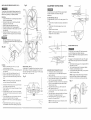
INSTALLING
AND
REMOVING BLADES
(FIG. Q)
Fig. Q
ADJUSTMENT
To avoid injury from accidental starting, always turn the
switch OFF and remove the plug from the power source
before moving, replacing, or adjusting the blade,
INSTRUCTnONS
Fig. T
To avoid injury, turn the switch OFF and unplug the band
saw from the power source before making any
adjustments.
Removing
1. Loosen the blade tension by turning the blade tension
knob (t) counterclockwise.
2. Remove the table insert (2), and remove the table
aligning pin (3) from the table.
3. Open the upper and lower wheel covers (4).
4. Remove the blade (5) from the blade guides (6).
5. Carefully pull the blade from the side slot (7) and from
the wheels (8).
6. Swing the left side of the blade toward you, turning
the blade so it wilt fit through the slot (9) in the table,
and remove.
6
5
%
TILTING THE TABLE (FIG. S)
The band saw table (1) tilts 0° to 45 ° to the right and 15 ° to
the left,
1. Loosen both star handle lock knobs (2) underneath the
table.
2, Tilt the table to the desired angle as shown on the
scale (3).
3, Tighten the two lock knobs.
NOTE: The 90 ° table stop bolt must be removed to tilt
the table 10° or more to the left,
Fig, S
Make sure the blade is in center of table insert slot(2)
Then Tighten the screw(A-C) which under the tabe both side.
as shown Fig Q-1
Fig Q-1
1
........
BLADE
"'"---
TENSION
(FIG, U)
To avoid injury, turn the switch OFF and disconnect the
saw from the power source before making any
adjustments. NEVER make tension adjustments with the
machine running.
"-.....
Installing
t.
Make sure the blade tension knob (!) is turned
counterclockwise
until it stops,
2. Remove the table insert (2) and the table aligning
from the table.
3.
4.
pin (3)
Open the upper and lower blade guard doors (4).
Guide the new blade (5) through the table slot (9),
making sure the blade teeth are pointing forward and
down.
MITER GAUGE (FIG. R)
A miter gauge (1) is supplied with your band saw to be used
with the table (2). The tabfe is equipped with a slot on the
right side of the blade for the miter gauge. The miter gauge
can be tilted 0° to 45 ° right or teft.
Fig. R
NOTE: To avoid lifting the workpiece,
the blade teeth
must point downward toward the table.
6.
7.
8.
Swinging the left side away and back, place the blade
on the upper and lower wheels {8}.
Place the blade carefully between the upper and fewer
blade guides (6).
Slide the blade into the slot (7) at the left of the wheets,
and make sure the b_ade is positioned at the middle of
the wheels.
Turning the blade tension knob clockwise, tighten the
tension until the blade is tight on the wheels.
10. Replace the table insert (2), and the table aligning pin
(3),
! 1. Adjust the blade tracking and tension propedy (See
ADJUSTMENT
section) before operating the band saw.
1
9.
2 ----
ADJUSTING THE 90 ° TABLE STOP (FIG. T)
1. Tilt the table to the front of the band saw,
2. Loosen the jam nut (1) on the table stop bolt (2) and
lower the stop bolt.
3, Tilt the table to the back until it rests on the stop bolt.
4. Place a combination square (3) on the table with the
hee! of the square against the blade (4),
5, Adjust the tilt of the table until it is 90 ° to the blade and
there is no space between the square and the blade.
Tighten the lock knobs.
6. Adjust the table stop bolt (2) up until it touches the
table. Tighten the jam nut (t),
7. Loosen the lock knobs and see if the table is iesting
on the stop bolt.
8, Check the square to make sure the table is still square
to the blade. If not, readjust the stop bolt.
9, When the adjustment is accurate at 90°, align the
pointer (5) on the scale (6) to 0°,
NOTE: The table stop bolt must be removed to tilt the
table 10°or more to the left.
The gauge (1) on the bracket (2) at the rear of the upper
wheel indicates the proper tension for the various blade
widths.
1. Set the blade tension gauge (1) to correspond with the
blade width, as shown.
2. Turn the blade tension knob (3) clockwise to tighten
the blade, counterclockwise to loosen.
3_ As you become familiar with the saw, you may want to
change the tension settings.
NOTE: Changes in blade width and type of material
being cut wilt have an effect on the blade tension,
Too much or too little tension could break the blade.
Fig. U
BLADE TRACKING
(FIG. V)
UPPER BLADE GUIDE ASSEMBLY
UPPER BLADE GUIDES AND BLADE SUPPORT
BEARING (FIG. X, Y)
(FIG.W)
To avoid injury, turn the switch OFF and disconnect the
saw from the power source before making any adjustments.
NEVER make tracking adjustments with the machine
running.
To avoid injury, turn the switch OFF and disconnect the
saw from the power source before making any
adjustments. NEVER make adjustments with the machine
running.
1.
1.
The blade (1) must be tensioned properly before
adjusting the tracking, (See BLADE TENSION on page 15).
2. Open the upper cover,
3. Move the blade guides (2) and support bearings (3)
away from the blade, if necessary. (See page 17).
4. Rotate the wheel (4) slowly forward by hand, and
check the position of the blade on the wheel. The blade
should remain centered on the wheel as it turns.
5. If the blade moves toward the front of the wheel, turn
the tracking knob (5) on the rear of the band saw
clockwise. This tilts the top of the wheel and moves the
blade toward the center.
6. if the blade moves toward the back edge, turn the
tracking knob counterclockwise, moving the blade
toward the center.
2.
Loosen the lock knob (1) and move the blade guide
assembly (2) to 1/8" above the workpiece.
Rotate the assembly, if necessary, until the guide
blocks (3) are flat (parallel) to the blade (4). Tighten the
lock knob.
2
3
Fig. V
4
NOTE: The blade support bearing prevents the blade
from moving back too far and damaging the saw teeth
setting.
12. Check the lateral position of the support bearing (8).
The vertical back edge of the blade (3) should overlap
the front face of the support bearing 1/16" to 1/8" to
the left of the right bearing edge, as shown.
To avoid injury, turn the switch OFF and disconnect the saw
from the power source before making any adjustments.
NEVER make adjustments with the machine running.
NOTE: Make sure the blade is tensioned and tracking
properly. Adjust the blade guides and support bearing after
each blade tension and tracking adjustment. When the upper
blade guides and support bearings are adjusted, the lower
guides and bearings should also be adjusted.
Fig.W
NOTE: Turn the tracking knob SLIGHTLY to make blade
tracking adjustments.
The blade guard has been removed for clarity of illustration.
To avoid injury never operate the band saw without all guards
in place and in working order.
Support bearing (Fig.Y)
9. Loosen the thumb screw (6).
10. Turning the rear knob (7), move the support beadng (8)
in or out, until the bearing is t/64" behind the blade.
!1. Tighten the thumb screw (6).
Fig. Y
Blade guides (FIG. X)
1. Make sure the blade is tensioned and tracking properly.
2. Loosen the front hex socket screws (1) with a hex
wrench.
3. Move the guide blocks (2) as close to the blade (3) as
possible without pinching it.
4. Using a feeler gauge, make sure the space between
guide block and the btade measures 0.02" (the thickness
of a dollar bill).
5. Tighten the hex socket screws,
6. Loosen the side thumb screw (4)_by turning
counterclockwise.
7. Turn the rear knob (5) to move the blade guide brackets
in or out until the guide blocks (2) are just behind the
blade teeth.
8,
f
7
Tighten the thumb screw.
Fig. X
2
16
6
17
LOWER
BLADE
GUIDES
AND
SUPPORT
BEARING
Fig. AA
(FIG. Z, AA)
To avoid injury, turn the switch OFF and disconnect the
saw from the power source before making any
adjustments. NEVER make adjustments with the machine
running.
3
NOTE: Make sure the blade is tensioned and tracking
properly. The lower blade guides and support bearings
should always be adjusted after the bIade is tensioned, the
tracking is adjusted, and the upper blade guides and upper
support bearings are properly adjusted.
9
2
Blade guides
1. Loosen both front hex socket screws (1) with a hex
wrench.
2. Move the guide blocks (2) as close to the sides of the
blade (3) as possible without pinching it.
3. Using the feeler gauge, measure the spaces between
the guide blocks and the blade. Adjust to 0.02".
4. Tighten the hex screws. (Fig. Z)
5. Loosen the side hex socket screw (4). Move the guide
block support bracket (6) in or out until the blocks are
just behind the saw teeth. Tighten the screw. (Fig. AA)
BASIC SAW OPERATIONS
To avoid twisting the blade do not turn sharp corners; saw
around corners.
"ON/OFF" SWITCH (FIG. BB)
The keyed switch is intended to prevent unauthorized
use of the band saw.
1. To turn the band saw ON insert the yellow key (1) into
the key slot (2) in the center of the switch.
2. Push the key firmly into the slot, then push switch
to the ON position to start the band saw.
3. To turn the band saw OFF push the switch to the
down position.
4. Remove the yellow switch key, when the saw has come
to a complete stop, by gently pulling it outward.
A band saw is basically a "curve-cutting" saw. It is not
capable of doing intricate inside cutting as can be done
with a scroll saw.
Remove the switch key whenever the saw is not in use.
Place it in a safe place and out of reach of children.
Fig. BB
2
I
GENERAL
CUTTING
For your safety, read and understand all GENERAL and
SPECIFIC SAFETY INSTRUCTIONS on pages 3-5 before
using the band saw.
\
To avoid blade breakage, fire or other damage or injury,
NEVER use this band saw to cut metals.
CUTTING CURVES
When cutting curves, carefully turn the workpiece so the
blade follows without twisting. If the curve is so sharp that
you repeatedly back up and cut new kerr, use a narrower
blade, or a blade with more set (teeth further apart). When
a blade has more set, the workpiece turns easier but the
cut is rougher.
When changing a cut, do not withdraw the workpiece from
the blade. The blade may get drawn off the wheels.
To change a cut, turn the workpiece and saw out through
the scrap material area.
Fig. Z
Support bearing
6. Loosen the bearing hex socket screw (7) with the hex
wrench.
7. Move the blade support bearing shaft (8) in or out until
the support bearing (9) is 1/64" behind the saw blade.
8. Tighten the bearing hex socket screw. (Fig. AA)
9. The back edge of the blade (3) should be positioned
1/16" to 1/8" from the right edge of the support bearing
(9), as shown. (Fig. Z)
tt is also used for straight line operations such as
crosscutting, ripping, mitering, beveling, compound cutting,
and resawing.
Operating band saws involves a certain amount of hazard.
Before attempting regular work, use scrap lumber to check
the settings, and to get the feel of operating the band saw.
Read instructions and ptan your work before cutting a
workpiece.
Do not turn the power ON until after you have made all
adjustments, checked that the guard is in place, and turned
the wheel by hand to make sure all parts work properly.
Always keep the guide assembly 1/8" above the workpiece.
Do not force the workpiece against the blade. Light contact
permits easier cutting and prevents unwanted friction and
heating of the blade.
Sharp saw blades need little pressure for cutting. Steadily
move the workpiece against the blade without forcing it.
When cutting long curves, make relief cuts as you go
along.
CIRCLE CUTTING (FIG. CC)
1. Adjust the guide assembly to 1/8" above the workpiece.
2. Use both hands while feeding the work into the blade.
Hold the workpiece firmly against the table. Use gentle
pressure. Do not force the work, ALLOW the blade to cut.
3. The smallest diameter circle that can be cut is
determined by the width of the blade. For example, a
1/4" wide blade will cut a minimum diameter of
approximately 1-1/2".
Fig. CC
\
Minimum
Z'D
'1
'1
2q/2"D
C#c_e Diameter
1/'2'.'
Blade
Width
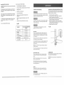
BLADE SELECTION
(FIG. DD)
Common causes of blade breakage:
CAUTION: Blade teeth are sharp. Use care when handling
a saw blade.
,,
Poor guide alignment and adjustment.
=
Forcing or twisting a wide blade around a short radius.
For longest wear and best cutting results, use the-correct
blade thickness, width, and temper for the type of material
you will cut.
•
Feeding too fast.
=
Dull teeth or not enough set.
•
Too much blade tension.
•
Setting top guide assembly too high above the
workpiece.
o
Lumpy or improperly finished braze or weld on the
blade.
o
Continuous running of blade when not cutting.
When sawing small curves and delicate work, use narrow
blades. Otherwise, use the widest blade possible, See Fig, CC
on page 19.
For cutting wood and similar materials with this band saw,
purchase blades in widths up to 1/2", and a length of
93-1/2".
Do not cut metals with this band saw.
GENERAL
MAINTENANCE
ADJUSTING THE UPPER BLADE GUIDE TRAVEL (FIG, EE)
]f the upper guide bar assembly will not move up and down
easily or falls when the lock knob is loosened, the following
adiustment should be performed.
For your own safety, turn switch OFF and remove the plug
from power source receptacle before maintaining, cleaning,
adjusting, or lubricating your band saw.
1.
2.
3.
To avoid fire or toxic reaction, never use gasoline, naphtha,
acetone, Iacquer thinner or similar highly volatile solvents
to clean the band saw.
4.
Fig. DD
Operation
5.
Recommended Blade Width
0nches)
Cross Cutting
l/4, 3/8, 1/2
Mitering
1/4, 3/8, 1/2
Beveling
1/4, 3/8, 1/2
Compound Cutting
1/4, 3/8, !/2
Circle Cutting
See chart on pg. 19
Curve Cutting
1/8, I/4
Remove the guide bar lock knob (!).
Using a 5mm hex "L" wrench, tighten or loosen the
screw (2) located behind the lock knob.
Move the guide bar (3) up and down to check for smooth
movement and ability to hold its position.
Make further adjustments to the screw as required.
Properly adjusted, the guide bar should move smoothly
and hold its position when released.
Reinstall the guide bar lock knob.
Fig. EE
To avoid eye injury from blowing debris, wear safety
goggles when blowing out sawdust,
BAND SAW
Sawdust will accumulate under the table and base. This
could cause difficulty in the movement of the table when
setting up a band saw cut. Frequently blow out or vacuum
up the sawdust.
Keep your band saw clean. Remove the sawdust from the
inside. Vacuum or blow out frequently.
Do not allow filth to build up on the table, the guides, or the
support bearings. Clean them with Craftsman Gum and
Pitch Remover.
NOTE: Do not immerse the support bearings in the gum
and pitch remover.
Put a thin coat of paste wax on the table so that the wood
slides easily while cutting.
LUBRICATION
BLADE WHEEL TIRES
Pitch and sawdust that build up on the tires should be
removed with a stiff brush or scrape off with a piece of
wood.
All of the bearings are packed with grease at the factory.
They require no further lubrication.
CAUTION: Never put lubricants on the blade while it is
spinning.
NOTE: To avoid damaging the tires do not use a sharp
knife or any kind of solvent.
When the tires become worn they should be replaced.
When replacing the tires, stretch them around the wheels
but do not glue them on.
MOTOR
Frequently blow or vacuum out any sawdust from the
motor. Follow lubrication instruction on the motor label.
To avoid electrocution or fire, immediately replace a worn,
cut or damaged power cord.
...............
:_ ......
20
21
MOTOR
TROUBLESHOOTING
Problem
Probable
Noisy operation.
1. Incorrect belt tension.
GUUDE
To avoid injury from an accidental
2. Loose motor pulley.
3. Loose pulley cover.
start, turn the switch OFF and always remove the plug from the power source
Motor will not start,
Alf electrical or mechanical repairs should be done only by qualified service technicians. Contact the nearest Sears
Service Center.
GENERAL
Probable Cause
Problem
,,
,,' ........
..... ',_........
Remedy
,,,
,,
,",",,' ....
,......
Motor will not start and fuse
or circuit breaker opens,
1. Adjust tracking. See ASSEMBLY AND ADJUSTMENTS
section "BLADE TRACKING".
2. Replace blade.
Blade does not run in the
center of the
1, Not tracking properly.
upper wheel.
2. Defective blade.
Band saw slows down
when cutting.
1. Belt too loose.
1. Adjust belt tension. See ASSEMBLY AND
ADJUSTMENTS section "BLADE TENSION".
2. Cutting too small a radius.
2. Stop feeding, back up the material slightly, until the
band saw speeds up.
3. Replace blade.
4. Slow down, trying to cut too fast. See "MOTOR
TROUBLESHOOTING GUIDE" on page 23.
Blades braking
Blade duns too quickly.
Band saw vibrates.
Adjust tension. See ASSEMBLY AND
ADJUSTMENTS section "INSTALL THE BELT'.
2, Readjust and tighten motor pulley set screw,
3. Readjust and tighten pulley cover mounting
screws.
,
1, Not plugged into power
outlet.
1. Plug it into the power outlet.
2. Switch and key not in ON
position.
3. Motor cord cut or abraded.
2. Insert key and turn the switch ON.
4. Plug on cord is faulty.
5. Fuse on circuit breaks open.
6. Faulty motor
4. Take to Sears Service Center for new plug.
5. Reuset; may be too many machines on line.
6. Take to Sears Service Center for repair
or replacement.
t. Too many electrical
machines,
2. Incorrect fuse.
1. Turn off other machines and try again.
3. Wheels do not rotate.
4. Undersized extension cord,
3. Dull blade.
4. Overloading motor.
Remedy
before
making any adjustments,
,,,,,,,
Cause
1. Too much tension on
the blade.
2.
Kink in the blade caused by
cutting too small a radius or
turning the material too fast
when cutting.
1. Adjust tension, See ASSEMBLY AND
ADJUSTMENTS section "BLADE TENSION"
2. Use correct cutting technique.
See OPERATION section "GENERAL CUTTING".
1. Blade guides set too close to
the teeth.
1. Adjust upper and fewer blade guides.
2. Cutting incorrect material.
2. See OPERATION section "BLADE SELECTION".
1. Too much tension on
motor belt.
1, Adjust according to ASSEMBLY AND
ADJUSTMENTS section, "INSTALL THE 'BELT',
_i_!_i:i_i_ii_i_i_!i_i!_!_i_i_i_:i!i_i_i_i!i_!;_i!i_!!i_iii_!;:_!!i_ii_i!_i!i_!_!i_!_i!i_ii_ii_!!_i!:_!i_!i_:i_!_!_!
22 _i_i_i_i_i_i_!!i_ii_!i:i_ii!_:!i_i_i:ii%i_!_i_iii_ii_ii_ii!_!_!ii_ii_!_
:!i_%i%'_iiii
5, Short circuit.
3. Take to Sears Service Center for new cord.
2. Try time delay fuse, or go to circuit with higher
rated fuse or circuit breaker.
3. Unplug and turn wheels by hand, move
obstruction.
4. Use correct size extension cord; see page 5,
I 5. Cord, plug, or motor need repair; take to Sears
Service Center for repair.
Motor fails to develop
full power.
1, Low line voltage.
2. Faulty motor or capacitor.
1. Check power line for proper voltage.
2, Take to Sears Service Center for evaluation.
Motor overheats.
1. Overload on motor.
2. Poor ventilation of motor.
Provide better air circulation.
3, Capacitor failure.
1. Reduce load to motor, feed work slower into blade,
2. Unplug and clean out around motor; provide
better air circulation.
Motor stalls or slows,
1.
2.
3.
4.
l,
2.
3.
4.
Frequent fuse or circuit
breaker failure.
t. Motor overload.
2. Overload of electrical circuit.
3. Incorrect fuse or circuit
breaker.
Motor overload,
Low line voltage.
Loose wire connections.
Faulty motor.
3. Take to Sears Service Center for repair.
Reduce load to motor, feed work slower into blade.
Check power line for proper voltage.
Take to Sears Service Center for repair.
Take to Sears Service Center for repair.
1. Reduce load to motor, feed work "slower into blade.
2. Too many electrical appliances on same circuit.
3, Have electrician upgrade service to outlet.
CRAFTSMAN
CRAFTSMAN
BAND
When servicing use only CRAFTSMAN
product
137.224140
/
137.224140
SAW
BAND SAW
@
replacement parts. Use of any other parts may create a HAZARD or cause
damage,
Any attempt to repair or replace electrical parts on this band saw may create a HAZARD unless repair is done by a
quaIified service technician. Repair service is avaiIable at your nearest Sears Service Center.
Order by PART NUMBER,
net by key number
Key
Key
No.
PART
NUMBER
'Description
Size
1
2
3
4
3ADO0101
3AD00201
3ADOO301
3AD00401
U ppe r frame
Lock ha_ldle
NL=l
Guide post
5
6
7
8
g
3AD00501
3AD00601
3Ae00701
3AD00801
3AD00g01
Guide
Sector
Upper
Blade
Bearing
11
12
13
14
t5
16
17
18
19
3AD61101
3AD0"_201
3AD01301
3AD0!401
3AD01501
3AD0160t
3ADO170
t
3ADO180I
3ADO 1901
Blade guard block
t_-msion knob
Nameplate
Adjust
r_u_
Spdng
Siding
bracket
Square
r'_
Adjustmen_
knob
Shalt
h_nge
21
22
23
24
25
26
27
28
29
3AD02t01
3AD02201
3AD0230
!
3AD0240!
3AD02601
STD541050
3AD02701
3AD02801
3AD02901
Steel p_n
Uppel wheel
Bearing
Upper whee!
T_re
Hex nu_
Stad
Upper guard
Upper guard
3t
32
33
34
36
36
37
38
39
3AD0310t
3AD03201
STD551075
3AD03401
3AD03601
3AD03601
3AD0370t
3ADO380t
3AD03gol
alm
1
1
12
1
6/16"1-1/4
3/t6
support
sc:ew
spacEng
guard
bracke_
6"20
2
2
I
2
sleeve
6200ZZ
4
1
1
2
1
1
t
!
1
6ram
3/8
5/16"2
2
1
2
t
2
1
2
1
1
shall
6202ZZ
1/2
inside
outside
Set pm
He× bolt
Fla_ washer
Base
Hex r_ul
Blade
Table Ense_t
_able pin
1able
3/4"2-1
3/4
f2
3/4
14"" I4"
4
1
2
t
1
!
1
1
1
_2............
_.D!_4?r_!
.............
S_t_. _'1"_:2t_!
.................
!£:_°........ _..............
41
3ADO4101
Trunnion
clamp
42
43
44
3AD64201
3ADO4301
3AD04401
Tr u_]n_on
Hex screw
Hex bol_
45
46
47
46
3AD04501
3AD04601
STD561025
STD512506
Truan_on supp0r_
Star knob
Spnag
washer
Set screw
49
3AD04901
Hex
shoe
2
I/4"5/8
5/16"1-1/4
2
6
2
10turn
5/16
1i4 _1/2
1
2
6
3
5/16'3"
!
bracket
bol_
_o............
_5/?o._93!
.............
9_z1:'}.9,
.................................
s:.16 .............
.2...............
51
52
3AD06101
3AD0520t
Set screw
Hex ntll
w/i washer
53
54
3AD06301
STD551026
Hex bol_
Flat washer
5-5
56
57
58
59
3AD05501
3AD05601
3AD05701
3AD0580t
3AD05901
Lewer g:mde
Set screw
H,age
Set screw
Plale
61
62
63
64
65
66
67
68
69
3AD06101
3AD06201
3AD06301
3AD06401
3ADO6501
3AD0660"_
3AD06701
3AD06801
3AD06901
Power cold s_orage
Set screw
Pufley
Hex screw
Snap ring
Bea_rlg
Lowe_ wheel
Hex screw
Lower door
3/16"3/8
5/16
2
1
1/4'3/4
1/4
2
2
supper_
6" 10
3/t6'3/6
6" 10
6"
5t16"2
R_34
6204ZZ
1/4"5/8
No.
PART
NUMBER
Description
Size
Qty
1/4"1/4
1
1
3
\
Qty
1
3
1
2
2
2
2
1
4
2
2
1
1
1
70
71
72
3AD07OO
3ADO7101
3AD0720!
l
Guard
Motor coJ]ar
6el screw
73
74
75
3AD07301
3AD07401
3AD07501
Flat washe_
Plale
Cord
r'eoto_
76
77
78
79
3AD07601
3AD07701
STD551031
3AD07901
Stra_
rebel
Power cord
Flal washer
Hex screw
80
81
82
83
3AD06001
3AD0Sl01
3AD08201
ST D551031
Dual chute
Key
Hex screw
Flal was he_
5"5'30
5/16"1
5/16' 16
64
66
66
87
68
89
3AD08401
3AD08601
3AD08601
3AD08701
3AD08801
3AD08901
Molor
Key
Nut
Adjust screw
Motor pulley
Pan
head
screw
5" 5"23
6/16
6" 45
2-t/2
31_6"3/8
90
9t
92
g3
94
95
96
97
98
99
3ADOgo01
3AD09101
3AD09201
3AD09301
3AD09401
3AD0gS0t
3AD09601
3AD09701
3AD0gB01
STD541631
Switch
Tooth washer
V bel_
Pulley cover plate
Set screw wii washer
Putiey cover
Set screw wii washer
Frame areq cover, lower
Frame arm cover
upper
Nut
100
101
102
103
104
3ADt0001
3AD10101
3ADt0201
3ADI030t
3ADt040t
P_n
Brush
Shaft
Poinler
Scale
3" 10
105
106
t07
106
109
3AD 10501
3AD10601
3AD10701
3AD10801
3AD10901
Nul
Set screw wii washer
Copper
washer
St ud
Set screw
w/i washer
5116
3t16"1/4
110
111
112
113
114
115
! 16
! 17
1 t8
3AD11001
3ADt 1101
3AD11201
3ADl130t
3ADI taOl
3AD11601
3AD11601
3AD11701
3AD!1801
Milef 9augu
Y Type black
Flat washe_
Knob
Headless
screw
Spmlg
Stee! ball
Spring
washer
Holde_
brush
5/16"'23
2
1
1
bushing
& plug
2
1
6
2
5t16"23
1/4"1/4
1
2
1
1
2
1
8
1
1
1
6ram
A.40
3ti 6"3/6
3/16"1/4
5/t6
4
2
2
2
2
3t16"1/2
3/16"14
16
1/4
3_16
!
2
2
!
I
1
1
2
1
.!._! .........._1_p.1.!?0!
...................
s£_ w.c:÷b£,
..................
_1!9!
.............
1_....
2061
Spring
plate
120
3AD:
122
123
! 24
125
126
127
128
STD551025
3AD1230t
3AD 1240 !
3AD12501
3AD12601
3AD12701
3A D t 280:1
Flal washer
Blade guard
Ctip head
Setscrew
Hex w_eoch
Set sere:>,' washer
Flat washer
1/4
3/16"1/4
3rr_m'_40L
3'16"38
3 _6
2
1
2
2
!
2
2
130
131
132
133
tAD 13001
3AD1310l
3AD3100I
C rl:/g
Set screw w/i washe_
Spring
Spring
washer
S-2O
3/16"1/4
3"20
3/4
1
12
1
1
3/16"3/8
3116"3/8
1
5
1
134
135
136
3AD13501
Set screw
Pan
head
Hinge
137
3AD
Sp_t]g
13761
137224140001
.3A9-1520-1
...........
' Not
washet
Owners
-
co_snectol
screw
5ram
)i
'
....
,,1"
1
1
300UFf125V
.
Shown
2
manual
Capac_to_
\
t
t
!
I
1
45
5 16"5
®
®
1
2
4
8
1
1
4
2
1
2
1
@
®
®
/
®
CRAFTSMAN
CRAFTSMAN
BAND
SAW LEG STAND
When servicing use only CRAFTSMAN
137=224140
replacement parts. Use of any other parts may create a HAZARD or cause
product damage.
Any attempt to repair or replace electrical parts on this band saw may create a HAZARD unless repair is done by a
qualified service technician. Repair service is available at your nearest Sears Service Center.
Order by PART NUMBER, not by key number
Key
Part No.
Description
Size
Qty
1
2
3
4
5
3AD3010t
3AD30201
3AD30301
3AD30401
3AD30501
Stand top plate
Leg
Lower bracket
Lower bracket
Screw
6
7
8
9
10
3AD30601
3AD30701
3AD30801
3AD31001
3AD31101
Washer
Nut :
Stronger plate
Pad
Miter gauge stOrage
32
32
2
4
l
!1
3AD3t201
Screw
2
(short)
(long)
1
4
2
2
32
BAND SAW LEG STAND
137.224140
C
:.:÷:.:.:.:+_
For repair
of ma or brand
a
ances
in your
own home...
.........
no matter who made it, no matter who sold it!
........
:::::::::::::::
1 ....800 4 MY HONESMAnytime,
,:,o:::,,:,-.:::
.........
,X+_;,2
v,'.',.;;,........
day or nigh t
;:":"
-:.a-;:.:.:
v:z;.,.;
(1 800469-4663)
www, sea rs,com
._4:,;x.
v;z_v;;
........
::2::_:::::
,-:.:-'-':.:.:
w_,z..,;
:÷:':'X'.":
":+:'_(_
÷:÷:,:÷:,
33X'*:'3:_
.,:÷:.:÷:.:÷"::÷::
To bring in products such as vacuums, lawn equipment and electronics
.:+:.:.:+:.....................
for
repair ' call for the location of your nearest Sears Parts & Repair Centero
:':::::"::;:::
,:.,,:...,:.:.:÷:._
.........:-:-:-:e÷
.......
ii:'[:i:i:ii
.........
...........
:':':':÷:':':
.......
.........
i::_:::::_
_':':':"-_÷:
1 =800 - 488 - 1222
:,:,:÷:,:÷:
::::::::;::::'_
;,:+:÷e
An ytime, day or night
;.,-,v.v_
www.sears.com
÷:'X':.:':,
'.:.'::;:_::_
:÷X':':",
..........
e:¢÷e:
:i:i:i:_4i
;.;,.:,;,:.:_
,*WtZ.'z,
:':':':"_':':
..,,,.::..":"as
For the replacement
_:..:_:_i_i_
parts
that you need to do-it-yourself,
:....::,..:..:::::i*';':;::!;i!!
and owner's manuals
accessories
1 - 800 -366- PART
call Sears
6.a.m.-
::::;÷:
:.::..:.,,......
PartsDirectS_!
!:_:::-:_:_:_:
"::':":
.:.:.:.:.:;::":.':::::::
11 p,m. CST,
.........
.::::::::-::
.::.:,.:,.i;-i'-:iii?::i
(1-800-366-7278)
i_'_i!!$i
..,.:,..
7 days a week
www.sears. com/partsdirect
!,.:i:i::.::.?._ii
:-:e+:_;
:::::::::._:_
"
.X÷:.:e:,
,:.:,:_,:;4
.,,.::.,..":::":":':"r":':
TOpurchase or inquire about a Sears Service Agreement:
:_..'a'÷...":':':':':':"
......
::'.::::.:::,..::
:::::::::.:::,
.;,:,;÷:÷,'
........
:÷:':':÷:':
•::x':÷:-:,
! 800 827 6655
:':':':':':':'
.:,:.:.:.:e'
:,:.,.::-:::::::
:::::::_-::::
:÷:':':'::':
CST Men
:+:e:÷:-:
':'X':':'X'
........
':'X;z3:':'
--
Sat
:::::::::::::;:
:.'x,:e:,:
............
;,*.*...v;
:;.;vw
':'):':÷:'!
:"='..........
::::::",.:::::: Para pedir servicio de reparacidn a domicilio,
i_iiii::} y para ordenar piezas con entrega a dornicilio:
i_j!:_ii
1-888-SU-HOGAR
s_
Au Canada pour service en franoais:
t -877-LE-FOYER
s_
(1-877-533-6937)
:._+:.,_:-:::::..:::::.,
ii!i!iii_ii
,!i,'i!iiiii[
i
_F÷:,Ya
-::_÷:,:;
==================================================================================================
.....................................................................
j!ii!ii_ii_i_i::':"
:;i_'i_[i
11-888-784-6427) _
iiii!_i_i!.!!!_::_
@ Regis[ered Trademark ir_ Trademark of Sears, Roebuck and Co
© Sears, Roebuck and Co.
© Marca Registrada/_
Marica de F&brica de Sears, Roebuck and Co.
FULL ONE YEAR WARRANTY
If this product fails due to a defect in material or workmanship
wiil repair it free of charge.
within one year from the date of purchase, Sears
Contact a Sears Service Center for repair.
If this prod uct is used for commercial
purchase.
or rental purposes, this warranty applies only for 90 days from the date of
This warranty gives you specific legat rights, and you may alsohave other rights which vary from state to state.
Sears, Roebuck and Co., Dept. 817 WA, Hoffman Estates,
IL60179
4/2000