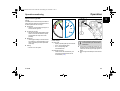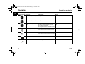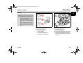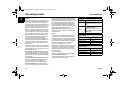
1
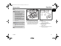
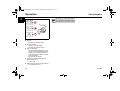
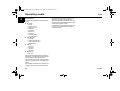
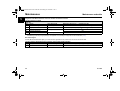
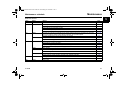
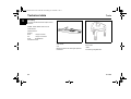
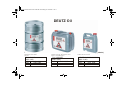
Acrobat-Dokument
OBJ_DOKU-16314-001.fm Seite 1 Donnerstag, 24. Juli 2008 11:18 11
Operation Manual
D/TCD 914
OBJ_DOKU-16314-001.fm Seite 2 Donnerstag, 24. Juli 2008 11:18 11
Notes
Notes
z This engine is defined exclusively for purpose
according to the scope of delivery and built by
the equipment manufacturer (use for the intended purpose). Any other use above and beyond
this will be considered as misuse. The manufacturer will not accept any liability for damages resulting from this. The user bears the sole risk.
z Use for the intended purpose also includes observance of the operating, maintenance and repair conditions specified by the manufacturer.
The engine should only be operated, serviced
and repaired by personnel trained in its use and
the hazards involved.
The pertinent rules for the prevention of accidents and other generally recognised safety and
industrial medicine rules must be observed.
z When the engine is running there is a danger of
injury caused by:
– rotating and hot components
– on motors with external ignition (high electrical voltage). Contact must be avoided!
z Unauthorised engine modifications will invalidate
any liability claims against the manufacturer for
resultant damage.
z Equally, manipulations to the injection and control system can affect the engine's performance
and the exhaust characteristics. Adherence to
legislation on pollution can no longer be guaranteed under such conditions.
z Do not change the cooling air feed area to the
blower of fan. An unobstructed cooling air supply
must be guaranteed.
The manufacturer will accept no liability for damage resulting from this.
z When carrying out maintenance work on the en-
2
gine, the use of DEUTZ original parts is prescribed. These are specially designed for your
engine and guarantee perfect operation.
Non-compliance results in the expiry of the warranty!
Maintenance/cleaning work on the engine may
only be carried out when the engine is not running and has cooled down.
When doing this, make sure that the electrical
system is switched off (remove ignition key).
The specifications for accident prevention with
electrical systems (e.g. VDE-0100/-0101/-0104/0105 Electrical protective measures against dangerous contact voltages) must be observed.
Cover all electrical components tightly when
cleaning with liquids.
z Do not work on the fuel system while the engine
is running - Danger to life!
Wait for the pressure to drop after the engine has
come to a standstill (in engines with DEUTZ
Common Rail about 5 minutes, otherwise
1 minute) because the system is under high
pressure - Danger to life!
During the first trial run do not stand in the danger area of the engine.
Danger due to high pressure in case of leaks Danger to life!
– In case of leaks immediately contact workshop.
– When working on the fuel system, make sure
that the engine is not started inadvertently
during repairs - Danger to life!
© 2008
OBJ_DOKU-16314-001.fm Seite 3 Donnerstag, 24. Juli 2008 11:18 11
Foreword
Dear customer,
Engine serial number
Congratulations on the purchase of your DEUTZ engine.
Please enter the engine serial number here. This will
simplify the handling of customer service, repair and
spare parts queries.
DEUTZ air/liquid-cooled engines are developed for a
broad spectrum of applications. Consequently, a
wide range of variants is offered to meet the requirements of specific cases.
The engine is equipped accordingly for the particular
installation situation, i.e. not all the components described in the operating manual are installed in your
engine.
Notes
We have endeavoured to highlight any differences
so that you will be able to locate the operating and
maintenance instructions applicable to your engine
more quickly and easily.
This document may only be reprinted and reproduced, even in part, with our express permission.
We reserve the right to make technical changes to
the descriptions and data in this operating manual in
the interest of further development of the engines.
Please make sure that this operating manual is available to everyone involved in the operation, maintenance and repair of the engine and that they have
understood the contents.
If you have any queries, please contact us, we'll be
happy to advise you.
Sincerely,
DEUTZ AG
© 2008
3
OBJ_DOKU-16314-001.fm Seite 4 Donnerstag, 24. Juli 2008 11:18 11
Contents
Notes . . . . . . . . . . . . . . . . . . . . . . . 2
Electrical system . . . . . . . . . . . . . . . 48
Foreword. . . . . . . . . . . . . . . . . . . . . 3
7 Faults. . . . . . . . . . . . . . . . . . . . . 50
1 General. . . . . . . . . . . . . . . . . . . . 5
Fault table . . . . . . . . . . . . . . . . . . 50
2 Engine description . . . . . . . . . . . . . 7
8 Transport and storage . . . . . . . . . . . 55
Model . . . . . . . . . . . . . . . . . . . . . 7
Transport . . . . . . . . . . . . . . . . . . . 55
Engine illustrations . . . . . . . . . . . . . . 9
Engine corrosion protection . . . . . . . . . 56
Schematic for lubricating oil . . . . . . . . . 13
9 Technical data . . . . . . . . . . . . . . . . 58
Schematic for fuel . . . . . . . . . . . . . . 15
Engine and setting data . . . . . . . . . . . 58
Exhaust return . . . . . . . . . . . . . . . . 16
Tools . . . . . . . . . . . . . . . . . . . . . 60
3 Operation . . . . . . . . . . . . . . . . . . 18
Ambient conditions . . . . . . . . . . . . . . 18
Initial start-up . . . . . . . . . . . . . . . . . 19
Start procedure . . . . . . . . . . . . . . . . 21
Operation monitoring . . . . . . . . . . . . . 23
Stop procedure . . . . . . . . . . . . . . . . 25
4 Operating media. . . . . . . . . . . . . . . 26
Lubricating oil . . . . . . . . . . . . . . . . . 26
Fuel . . . . . . . . . . . . . . . . . . . . . . 28
5 Maintenance . . . . . . . . . . . . . . . . . 30
Maintenance schedule . . . . . . . . . . . . 30
6 Servicing and maintenance works . . . . . 33
Lubricating oil system. . . . . . . . . . . . . 33
Fuel system. . . . . . . . . . . . . . . . . . 36
Engine cleaning. . . . . . . . . . . . . . . . 38
Aspiration system. . . . . . . . . . . . . . . 39
External exhaust return . . . . . . . . . . . . 42
Belt drives . . . . . . . . . . . . . . . . . . 43
Setting work . . . . . . . . . . . . . . . . . 46
4
© 2008
OBJ_DOKU-16314-001.fm Seite 5 Donnerstag, 24. Juli 2008 11:18 11
General
DEUTZ diesel engines
DEUTZ diesel engines are the product of years of research and development. Profound know-how combined with high quality requirements are the
guarantee for the production of engines with a long
life, high reliability levels and low fuel consumption.
Obviously the high requirements for the protection of
the environment are also met.
Safety precautions when the engine is running
Maintenance work or repairs may only be performed
on the shut-down engine. Make sure that the engine
cannot be started inadvertently - Danger of accident!
After repair work: Check that all guards have been
replaced and that all tools have been removed from
the engine.
Observe industrial safety regulations when running
the engine in an enclosed space or underground.
When working on the running engine, work clothing
must be close fitting.
Never fill the fuel tank while the engine is running.
Service and Maintenance
Service and maintenance are also decisive for
whether the engine satisfactorily meets the set demands. Recommended service intervals must therefore be observed and service and maintenance work
must be carried out conscientiously.
velopments for improving the engines are also introduced in the original DEUTZ parts of course. Only
the use of original DEUTZ parts manufactured according to the state-of-the-art can guarantee perfect
functioning and high reliability.
ity with notes on product responsibilities and services. Or you can use another fast, convenient way via
the Internet under www.deutzshop.de. The DEUTZ
P@rts Online parts catalogue gives you a direct contact to your nearest local service partner.
DEUTZ Xchange components
California
Proposition 65 Warning
Diesel engines and some of its constituents are
known to the State of California to cause cancer,
birth defects and other reproductive harm.
DEUTZ replacement parts are a low-cost alternative.
Of course, the quality standards here are just as high
as for new parts. DEUTZ replacement parts are
equal to the original DEUTZ parts in function and reliability.
DEUTZ AG
The gaskets used in this engine contain no asbestos.
Please use the appropriate original DEUTZ parts for
maintenance and repair work.
Ottostraße 1
Service
Phone:
We want to preserve the high performance of our engines, and with it the confidence and satisfaction of
our customers. We are therefore represented worldwide by a network of service branches.
Fax:
+49 (0) 221-822-5850
E-Mail:
[email protected]
Original DEUTZ parts
Original DEUTZ parts are subject to the same strict
quality demands as the DEUTZ engines. Further de-
The DEUTZ home page gives you a continuously upto-date overview of the service partners in your vicin-
© 2008
51149 Köln
Germany
+49 (0) 221-822-0
www.deutz.com
The DEUTZ name does not merely stand for engines
that are the products of extensive development
work, DEUTZ also stands for complete service packages that ensure optimum operation of our engines,
and for customer services operations that you can
count on.
Please contact your DEUTZ-partner in case of malfunctions and sare parts inquiries. Our specially
trained personnel will ensure fast, professional repairs using original DEUTZ spare parts in case of
damage.
Special care should be taken under abnormally demanding operating conditions.
Masthead
Asbestos
5
1
OBJ_DOKU-16314-001.fm Seite 6 Donnerstag, 24. Juli 2008 11:18 11
General
1
Danger
This symbol is used for all safety instructions which, if not observed, present a direct danger to life and limb for the person
involved. Observe these carefully. The attention of operating personnel should be
drawn to these safety instructions. Furthermore, the legislation for "general regulations for safety and the prevention of
accidents" must be observed.
Caution
This symbol indicates a danger to the part
and engine. The relevant instructions must
be observed, failure to do so can lead to destruction of the part and the engine.
Notes
This symbol accompanies notes of a general kind.
6
© 2008
OBJ_DOKU-16314-001.fm Seite 7 Donnerstag, 24. Juli 2008 11:18 11
Engine description
Model
2
Engine type designation
This manual covers the following engine types
D 914 L06
B
A
TCD 914 L06
D 914 L05
D 914 L04
Mot.-Typ
C
Mot.-Nr.
D 914 L03
TCD
T
Exhaust gas turbocharger
C
Charge air cooler
D
Diesel
914
Series
914
L03/L04/L05/L06
L
in series
03
No. of cylinders
04
No. of cylinders
05
No. of cylinders
06
No. of cylinders
© 2008
R
DEUTZ AG
MADE IN GERMANY
Rating plate
Location of the rating plate
The type (A), engine number (B) and performance
data are stamped on the rating plate.
The rating plate (C) is fixed to the cylinder head cover or the crankcase.
The engine type and number must be stated when
purchasing spare parts.
7
OBJ_DOKU-16314-001.fm Seite 8 Donnerstag, 24. Juli 2008 11:18 11
Engine description
2
D
Model
left
right
1
Engine serial number
Cylinder numbering
The engine number (D) is stamped onto the crankcase (arrow) and onto the rating plate.
Cylinder arrangement
The cylinders are counted consecutively starting
from flywheel (1).
Direction of rotation
Looking onto the flywheel.
rotating to the left: counter-clockwise.
Engine sides
Looking onto the flywheel.
8
© 2008
OBJ_DOKU-16314-001.fm Seite 9 Donnerstag, 24. Juli 2008 11:18 11
Engine description
Engine illustrations
2
D 914 L06
View from right (example)
13
12
11
1
10
2
1
2
3
4
5
6
7
8
9
10
11
12
13
Cooling fan
V-belt (fan)
Tension pulley
Lubricating oil filling
Lubricating oil sump
Fuel supply pump with integrated screen filter
Stop magnet
Lubricating oil dipstick
Injection pump
Lube oil replacement filter
Exchangeable fuel filter
Air guide hood
Cylinder head cover
9
8
7
3
6
© 2008
5
4
9
OBJ_DOKU-16314-001.fm Seite 10 Donnerstag, 24. Juli 2008 11:18 11
Engine description
2
Engine illustrations
D 914 L06
View from left (example)
1
2
3
4
10
Air intake pipe
Exhaust manifold line
Flywheel
Starter
© 2008
OBJ_DOKU-16314-001.fm Seite 11 Donnerstag, 24. Juli 2008 11:18 11
Engine description
Engine illustrations
2
TCD 914 L06
View from right (example)
1
2
3
4
5
6
7
8
9
10
11
12
13
14
15
© 2008
Turbocharger
Generator
Tension pulley
Cooling fan
Lubricating oil filling
Fuel supply pump with integrated screen filter
Lubricating oil dipstick
Stop magnet
Injection pump
Lube oil replacement filter
Lube oil cooler
Exchangeable fuel filter
Air guide hood
Injection valve
Cylinder head cover
11
OBJ_DOKU-16314-001.fm Seite 12 Donnerstag, 24. Juli 2008 11:18 11
Engine description
2
Engine illustrations
TCD 914 L06
View from left (example)
1
2
3
4
5
6
7
8
9
12
Charge air cooler
Flywheel
Starter
Lubricating oil sump
Lubricating oil pipe to the turbocharger
Exhaust outlet
Turbocharger
Combustion air inlet
Exhaust manifold line
© 2008
OBJ_DOKU-16314-001.fm Seite 13 Donnerstag, 24. Juli 2008 11:18 11
Engine description
Schematic for lubricating oil
2
D 914
(example)
1
2
3
4
5
6
7
8
9
10
11
© 2008
Lubricating oil sump
Lubricating oil pump
Pressure holding valve
Lube oil cooler
Lubricating oil filter
Overpressure valve
Main lube oil channel
Rocker arm
Lubricating oil pressure indicator
Injection pump
Connection possibility for cab heating
Retrofitting by authorised specialists only
13
OBJ_DOKU-16314-001.fm Seite 14 Donnerstag, 24. Juli 2008 11:18 11
Engine description
2
Schematic for lubricating oil
TCD 914 L06
(example)
1
2
3
4
5
6
7
8
9
10
11
12
13
14
Lubricating oil sump
Lubricating oil pump
Pressure holding valve
Lube oil cooler
Lubricating oil filter
Overpressure valve
Main lube oil channel
Sub-stream lubricating oil filter
Rocker arm
Lubricating oil pressure indicator
Turbocharger
Injection pump
Connection possibility for cab heating
Retrofitting by authorised specialists only
© 2008
OBJ_DOKU-16314-001.fm Seite 15 Donnerstag, 24. Juli 2008 11:18 11
Engine description
Schematic for fuel
Fuel schematic (example)
1
2
3
4
5
6
7
8
© 2008
Fuel tank
Fuel line from tank to fuel pump
Fuel supply pump with integrated screen filter
Exchangeable fuel filter
Injection pump
Injection line to injection valve
Injection valve
Fuel return to fuel tank
15
2
OBJ_DOKU-16314-001.fm Seite 16 Donnerstag, 24. Juli 2008 11:18 11
Engine description
Exhaust return
2
External exhaust gas recirculation
7
D 914 L03 > 37 kW
D 914 L04
D 914 L05
D 914 L06
TCD 914 L06 Optional
(example)
5
1
6
1 Exhaust gas partial flow
(not connected)
2 Valve housing
3 Actuator
(electrically actuated)
4 Distributor pipe
5 Electrical connection
6 Switch
The switch is connected internally with the control linkage. The voltage to the actuator is interrupted at load peaks.
7 Injection pump
The switch housing is designed to be safe from manipulation.
Only have work performed on the components by
authorised qualified personnel.
4
16
2
3
© 2008
OBJ_DOKU-16314-001.fm Seite 17 Donnerstag, 24. Juli 2008 11:18 11
Engine description
Exhaust return
2
Internal exhaust gas recirculation
(example)
D 914 L03 < 37 kW
TCD 914 L06 Optional
1
3
[mm]
2
1 Additional cams for exhaust gas recirculation
Inlet valve opens briefly during the outlet cycle
and emits an exhaust gas partial flow to the suction system.
This partial volume is sucked back in in the next
suction cycle.
2 Outlet valve
3 Inlet valve
1
[°]
© 2008
17
OBJ_DOKU-16314-001.fm Seite 18 Donnerstag, 24. Juli 2008 11:18 11
Operation
3
Ambient conditions
Cold start aid
z Depending on the type of engine, glow plugs,
heating plugs, heating flange, flame glow system
can be used as cold starting aids.(21)
High ambient temperatures, high altitude
0 °C
This engine can be equipped optionally
with an electronic DEUTZ control unit.
Under the operating conditions listed below, the amount of fuel is reduced automatically, controlled by the electronic control
unit.
Under the following application and operating conditions, the amount of fuel must be reduced.
Low ambient temperatures
Lubricating oil
z Select the lubricating oil viscosity according to
the ambient temperature.
z If cold starting occurs frequently cut the lube oil
changing interval by half.
Fuel
z Use winter fuel below 0 °C (28).
Battery
z A good charging condition of the battery (48)
is the prerequisite for starting the engine.
z Heating up the battery to approx. 20°C improves
the starting behaviour of the engine. (Remove
and store the battery in a warm room).
18
z above 1000 m altitude
z above 30 °C ambient temperature
Reason: Air density decreases as altitude or ambient
temperature increase. This reduces the amount of
oxygen in the engine intake air and the fuel-air mixture would be too rich if the injected amount of fuel
were not reduced.
z The results would be:
– black smoke in the exhaust
– high engine temperature
– reduction in engine performance
– possible impairment of starting behaviour
Consult your equipment supplier or DEUTZ partner if
you have any other questions.
© 2008
OBJ_DOKU-16314-001.fm Seite 19 Donnerstag, 24. Juli 2008 11:18 11
Operation
Initial start-up
Preparations for initial commissioning
(Maintenance schedule E 10)
3
ing oil filler neck.
z Observe the lubricating oil filling level (58).
z Remove engine corrosion protection
z Remove any transport devices.
z Check the battery and cable connections and
mount if necessary.
z Check belt tension (43).
z Have the engine monitor or warning system
checked by authorised personnel.
z Check the engine mounting.
z Check that all hose unions and clips fit properly.
The following additional work must be carried
out on generally overhauled engines:
z Check the fuel pre-filter and main filter and
change if necessary.
z Check the intake air cleaner (if available, maintain according to maintenance indicator).
z Drain lubricating oil and condensation water from
the charge air cooler.
z Fill with engine lube oil.
Fill with engine lube oil
Low lubricating oil level and overfilling lead
to engine damage.
The engines are generally supplied without
lubricating oil filling.
Select lubricating oil quality and viscosity
before filling.
Order DEUTZ lubricating oils from your
DEUTZ partner
Pour in fuel
Only re-fuel when the engine is not running.
Ensure cleanliness.
Do not spill fuel.
Additional venting of the fuel system by a 5
minute trial run at idle speed or on low load
is absolutely essential.
z The fuel low pressure system must be vented before the first start-up after filling with the manualy
supply pump.
Only use clean commercially available brand diesel
fuel. Observe fuel quality (28).
Use summer or winter-grade fuel, depending on the
ambient temperature.
z Fill the engine with lubricating oil via the lubricat-
© 2008
19
OBJ_DOKU-16314-001.fm Seite 20 Donnerstag, 24. Juli 2008 11:18 11
Operation
3
Initial start-up
Trial run
Additional venting of the fuel system by a 5
minute trial run at idle speed or on low load
is absolutely essential.
Carry out a brief trial run up to operating temperature
(approx. 90 °C) after preparations.
Do not load the engine if possible.
z Work with the engine not running:
– Check engine for tightness.
– Check lubricating oil level, if necessary top
up.
z Work during the trial run:
– Check engine for tightness.
20
© 2008
OBJ_DOKU-16314-001.fm Seite 21 Donnerstag, 24. Juli 2008 11:18 11
Operation
Start procedure
3
Starting
Before starting, make sure that nobody is
standing in the immediate vicinity of the engine or work machine.
Disconnect the engine by uncoupling devices to be driven where possible.
After repair work: Check that all guards
have been replaced and that all tools have
been removed from the engine.
When starting with the flame glow plug/
glow plug/heating flange system do not use
any other starting aid (e.g. injection with
start pilot). Risk of accident!
Do not actuate the starter for more than
20 seconds. If the engine does not start up,
wait for one minute and then repeat the
starting process.
If the engine does not start up after two attempts, determine the cause as per fault table (50).
Do not run up the engine immediately to
high idling speed / full load operation from
cold.
Disconnect the engine by uncoupling devices to be driven where possible.
© 2008
© 25745-0
Starting
Without cold start aid
z Move speed adjustment lever (1) to slow idle.
z Turn shutdown lever (2) to position "I" and start.
z In electrical start with a lifting magnet the shutoff
lever (2) is pulled in direction "I" and held when
current is applied. The charging control lamp and
lubricating oil pressure control lamp go out.
z Insert key.
z Turn key to the right.
– Position 1 = operating voltage.
– Pilot lamps (1) and (2) light up.
z Push the key in and turn further clockwise
against spring pressure.
– Level 2 = no function.
– Level 3 = start.
z release the key as soon as the engine starts up.
– The pilot lamps will go out.
21
OBJ_DOKU-16314-001.fm Seite 22 Donnerstag, 24. Juli 2008 11:18 11
Operation
3
A
Start procedure
After starting, any exhaust gas turbidity in
the runup phase can be reduced by holding
the key at stage 2. (maximum 3 minutes)
B
C
with cold starting device
z Insert key.
– Position 0 = no operating voltage.
z Turn key to the right.
– Position 1 = operating voltage.
– Pilot lamps (A), (B) and (C) light up.
z stage 2 = pre-heating
– Preheat until the glow display goes out; an
error has occurred if the preheating indicator
flashes; e.g. the preheating relay is stuck,
which can discharge the battery completely
when at a standstill.
– Engine is ready for operation.
z Push the key in and turn further clockwise
against spring pressure.
– Level 3 = start.
z release the key as soon as the engine starts up.
– The pilot lamps will go out.
22
© 2008
OBJ_DOKU-16314-001.fm Seite 23 Donnerstag, 24. Juli 2008 11:18 11
Operation
Operation monitoring
3
Operation monitoring by EMR2
Optional
The EMR2 system monitors the engine condition as
well as the engine electronics and displays these to
the driver/operator with the error lamp:
z Function test
– Ignition on, error lamp lights up for approx. 2
seconds and then goes out.
z The lamp does not light
– After the lamp test an extinguished lamp indicates an error-free and trouble-free operating state within the scope of the control
possibility.
z Steady light
– If a lamp lights steadily a monitored measuring variable (e.g. coolant temperature, lubricating oil pressure) has left the permissible
value range.
z Flashing
– Serious error in the system.
Display instrument
Possible displays:
z Colour scale
– Display of operating state by coloured areas:
– green = normal operating state
– red = critical operatng state
Take suitable action.
z Measured value scale
– Actual value can be read off directly. The
nominal value should be taken from the
Technical Data (58).
© 2008
V-belt monitoring
A warning device for tearing of the V-belt
must be provided by the customer/device
manufacturer.
z In the event of V-belt tear the pressure pin (1) of
the electrical switch is actuated by the tensioning
roller and an acoustic signal or light signal is initiated.
z Stop the engine immediately to avoid overheating.
23
OBJ_DOKU-16314-001.fm Seite 24 Donnerstag, 24. Juli 2008 11:18 11
Operation
3
Operation monitoring
Instruments and symbols
Instruments/symbols Designation
Possible display:
Measure
Lubricating oil pressure display
Lubricating oil pressure below minimum
Switch off engine
Lubricating oil pressure display
Lubricating oil pressure in the red area
Switch off engine
Lubricating oil temperature display
The temperature display should always be in the
green area and only be in the yellow-green area
under exceptional circumstances
If the pointer enters the orange sector, the engine is
overheating.
Turn off and establish the cause from the Fault
Table
Lubricating oil pressure pilot lamp If the pilot lamp lights up after starting the engine or
while the engine is running, the lubricating oil pressure is too low
Switch off engine
Lube oil level
If the pilot lamp lights up after starting the engine or Check lubricating oil level / if necessary top up
while the engine is running, the lubricating oil level is
too low
Operating hours counter
Indicates the previous operating time of the engine
Observe the maintenance intervals
Horn
With acoustic signal
See Fault Table
123
24
© 2008
OBJ_DOKU-16314-001.fm Seite 25 Donnerstag, 24. Juli 2008 11:18 11
Operation
Stop procedure
3
Shutting off
Avoid switching off from full load (coking/
blockage of the remaining lubricating oil in
the turbocharger bearing housing). The lubricating oil supply of the turbocharger is
then no longer guaranteed! This shortens
the life of the turbocharger.
Run the engine in low idling speed for approximately one minute after relieving the
load.
The control unit remains active for about
another 40 seconds to save the system
data (lag) and then switches off automatically.
© 2008
A
B
C
Electrical shutdown (optional)
Shutting off
z Run engine up to idling speed.
z Move the key to position 0.
Control lamps A+B+C go out.
A = charge pilot light
B = lube oil pressure pilot light
C = pilot light for pre-heating system
0 = gear position: switch off engine
z Run engine up to idling speed.
z Move the key to position 0.
Control lamps A+B+C go out.
z In case of electrical shutdown or power failure
the shutoff lever (2) is switched off by the lifting
magnet up to engine standstill. The charging
control lamp and lubricating oil pressure control
lamp light up.
25
OBJ_DOKU-16314-001.fm Seite 26 Donnerstag, 24. Juli 2008 11:18 11
Operating media
4
General
Modern diesel engines place very high demands on
the lubricating oil to be used. The specific engine
performances which have increased constantly over
the last few years lead to an increased thermal load
on the lubricating oil. The lubricating oil is also more
exposed to contamination due to reduced oil comsumption and longer oil change intervals. For this
reason it is necessary to observe the requirements
and recommendations described in this operating
manual in order not to shorten the life of the engine.
Lubricating oil
perature and oxidation stability as well as a relatively
low cold viscosity. Since some processes relevant to
the definition of the lube oil change intervals are not
essentially dependent on the lube oil quality (such as
the incorporation of soot and other contaminations),
the lube oil change interval when using synthetic
lube oils may not be increased in relation to the specifications of the lube oil change intervals.
Biodegradable lubricating oils may be used in
DEUTZ engines if they meet the requirements of this
operating manual.
Recommended quality class
DEUTZ
Others
DQC II - 05
ACEA E3-96; E4-07; E5-02; E7-04
API CH-4/CG-4; CI-4,CI-4, CJ-4;
DHD-1
DQC III - 05 Please contact your DEUTZ partner
or see www.deutz.com
DQC IV - 05 \SERVICE \Operating Media and
Diagnosis\Deutz Quality Class\DQC
Release List
Lubricating oils always consist of a base oil and an
additive package. The most important tasks of a lubricating oil (e.g. wear protection, corrosion protection, neutralisation of acids from combustion
products, prevention of coke and soot deposits on
the engine parts) are assumed by the additives. The
properties of the base oil are also decisive for the
quality of the product, e.g. with regard to thermal
load capacity.
Quality
In principle, all engine oils of the same specification
can be mixed. However, mixing of engine oils should
be avoided because the worst properties of the mixture are always dominant.
Lubricating oils according to other comparable specifications can be used as long as they meet DEUTZ
requirements. In regions in which none of these
qualities are available, please contact your responsible DEUTZ partner.
DEUTZ lubricating oils DQC III-05
TLX - 10W40 FE
The lubricating oil quality has a considerable influence on the life, performance and thus also on the
costs-effectiveness of the engine. It basically applies
that: The better the lubricating oil quality, the better
these properties.
The lubricating oil viscosity describes the flow behaviour of the lubricating oil depending on the temperature. The lubricating oil viscosity has no
influence and effect on the lubricating oil quality.
Lubricating oils are classified by DEUTZ according
to their efficiency and quality class (DQC: DEUTZ
Quality Class). It basically applies that: with increasing quality class (DQC I, II, III, IV) the lubricating oils
are more efficient and higher quality. The appended
quality class designation (- 02 / - 05) indicates in
which year the classification was made.
DEUTZ lubricating oils DQC II-05
TLS - 15W40 D
Container
Order number:
5 litre container
0101 6331
20 litre container
0101 6332
209 litre barrel
0101 6333
Container
Order number:
5 litre container
0101 6335
or see www.deutz.com
20 litre container
0101 6336
\SERVICE \Operating Media and Diagnosis\Deutz
Quality Class\DQC Release List
209 litre barrel
0101 6337
The following lubricating oils are recommended for
the engines in this operating manual:
Synthetic lubricating oils are used increasingly
and have advantages. These oils have a better tem-
26
© 2008
OBJ_DOKU-16314-001.fm Seite 27 Donnerstag, 24. Juli 2008 11:18 11
Operating media
Lubricating oil
z The intervals depend on:
– lubricating oil quality
– sulphur content in the fuel
– type of application of engine
z The lubricating oil change interval must be
halved if at least one of the following conditions
applies:
– Constant ambient temperature below -10 °C
(14 °F) or lube oil temperature below 60 °C
(84 °F).
– Sulphur content in the diesel fuel of 0.5-1 %.
In case of fuels containing more than 1% sulphur, contact your corresponding DEUTZ
partner.
– operation with bio-diesel fuel
z If the lubricating oil change intervals are not
reached within a year, the oil should be changed
at least once a year.
The viscosity is classified according to SAE. Multipurpose lubricating oils should be used basically.
Single-purpose lubricating oils can also be used in
enclosed, heated spaces at temperatures >5 ° C.
35
30
25
20
Depending on the ambient temperature we recommend the following common viscosity classes:
15
The prescribed lubricating oil quality must
be observed when selecting the viscosity
class!
5
10
SAE 20W-50
Lubricating oil change intervals
40
SAE 15W-40
0101 7850
SAE 10W-40
209 litre barrel
45
SAE 10W-30
0101 7849
4
°C
SAE 5W-40
20 litre container
The ambient temperature at the installation site or in
the application area of the engine is decisive for
choosing the right viscosity class. Too high a viscosity can lead to starting difficulties, too low a viscosity
can endanger the lubrication effect and cause a high
lubricating oil consumption. At ambient temperatures
below -40 °C, the lubricating oil must be pre-heated
(e.g. by storing the vehicle or the machine in a hall).
SAE 5W-30
Order number:
SAE 0W-40
Container
Viscosity
SAE 0W-30
DEUTZ lubricating oils DQC IV-05 synthetic
0
-5
-10
-15
-20
-25
-30
-35
-40
© 2008
27
OBJ_DOKU-16314-001.fm Seite 28 Donnerstag, 24. Juli 2008 11:18 11
Operating media
4
Permissible fuels
The following fuel specifications / standards are approved:
z Diesel fuels
– EN 590
– ASTM D 975 1-D
– ASTM D 975 2-D
– BS 2869 A1
– BS 2869 A2
– NATO F-54
– NATO F-75
– JIS K2204 Grade 1
– JIS K2204 Grade 2
z Light heating oils
– DIN 51603
– ASTM D 396 Grade No. 1
– ASTM D 396 Grade No. 2
– BS 286 Class D
z Jet fuels
– NATO F34
– NATO F35
– NATO F44
– NATO F63
z Biodiesel fuel
– EN 14214
Fuel
els specified in the laws. These correspond to the
diesel fuels in accordance with EN 590 and
ASTM D 975 described in the operation manual. No
emission values are guaranteed with the other fuels
described in this operation manual.
The respective fuels prescribed by law must be used
to comply with the national emission regulations
(e.g. sulphur content).
Use commercially available fuels with a sulphur content below 0.5 %. The lubricating oil change intervals
must be halved at a higher sulphur content.
If other fuels are used which do not meet the requirements of the operating manual, the warranty will be
voided.
The certification measurements for compliance with
the legal emission values are made with the test fu-
28
© 2008
OBJ_DOKU-16314-001.fm Seite 29 Donnerstag, 24. Juli 2008 11:18 11
Operating media
Fuel
4
Winter operation with diesel fuel
Only carry out mixing in the tank. Fill with
the appropriate amount of paraffin first,
then add the diesel fuel. Normal and high
grade fuels may not be mixed.
At low ambient temperatures paraffin discharges can
lead to blockages in the fuel system and cause operating faults. Below 0 °C ambient temperature use
winter diesel (down to -20 °C) (filling stations provide
this in good time before the cold season starts).
z Below -20 °C paraffin should be added. The relevant percentages are given in the adjacent diagram.
z Special diesel fuels can be used for arctic climates to -44 °C.
If it is necessary to use Summer diesel fuel below
0 °C, up to 30 % petroleum can be added according
to the diagram opposite.
I
Summer-grade diesel fuel
II Winter-grade diesel fuel
A Outdoor temperature
B Percentage of paraffin to be added
Usually a sufficient cold resistance can be achieved
by adding a flow improver. Ask your DEUTZ partner.
© 2008
29
OBJ_DOKU-16314-001.fm Seite 30 Donnerstag, 24. Juli 2008 11:18 11
Maintenance
5
Maintenance schedule
Assignment of the DEUTZ maintenance and service schedules to maintenance intervals
Standard maintenance schedule
D/TCD 914
Stage
Activity
To be carried out by
E10
Initial commissioning
Authorised specialists
E20
Daily inspection
Operator
E30
Maintenance
Qualified personnel
E40
Extended maintenance I
E50
Extended maintenance II
1)
Maintenance interval every ....... operating hours (oh)
When commissioning new or overhauled engines
1x daily or every 10 operating hours in continuous operation
D 1000 1) / TCD 500 1)
1000
Authorised specialists
1.500
The lubricating oil load may be high depending on the application. The lubricating oil change interval must be halved here (27).
EPA-certified engines
The EPA (Environmental Protection Agency) is a US Government organisation for the protection of the environment and human health.
Deviations from the standard maintenacne schedule for engines subject to EPA certification
Stage
Activity
To be carried out by
E60
Intermediate overhaul
Authorised specialists
30
Maintenance interval every ....... operating hours (oh)
3.000
© 2008
OBJ_DOKU-16314-001.fm Seite 31 Donnerstag, 24. Juli 2008 11:18 11
Maintenance schedule
Maintenance
5
Maintenance measures
Stage
Activity
E10
E20
Check
Measure
Page
The measures are listed in chapter 3.
19
Lubricating oil level (if necessary top up)
33
Lubricating oil bath air filter
40
Engine tightness (visual inspection for leaks)
Suction air filter/dry air filter (maintain in accordance with maintenance indicator)
V-belts (retension or renew if necessary)
E30
Replace
Check
Lubricating oil An lubricating oil application/change strategy adapted optimally to the individual engine application
type can be created, for example, with the DEUTZ oil diagnosis. Ask your DEUTZ partner.
39
43
27/33
Lubricating oil filter/insert (every time the lubricating oil is changed)
27
Battery and cable connectors
48
Engine monitor, warning system Maintenance only to be carried out by authorised service personnel
E40
Check
Cold starting device
18
V-belts (retension or renew if necessary)
43
Engine mounting (tighten, replace if damaged when necessary)
Fastenings, hose unions / clips (renew if damaged)
Settings
Valve clearance
46
Replace
Sub-stream lubricating oil filter
35
Fuel filter cartridge
37
Fuel pre-cleaner / fuel pre-filter (change filter insert if necessary)
37
Suction air filter/dry air filter (maintain in accordance with maintenance indicator)
39
Switching valve of exhaust return
16
Clean
E50
Check
Injection valve
E60
© 2008
Replace
Injection valve
31
OBJ_DOKU-16314-001.fm Seite 32 Donnerstag, 24. Juli 2008 11:18 11
Maintenance
5
Stage
Maintenance schedule
Activity
Measure
Page
Replace
Switching valve of exhaust return
16
Clean
Charge air cooler entry area (drain lube oil/condensate)
Turbocharger compressor outlet
Every 2
years
Replace
Exhaust channels of exhaust return (cylinder head)
42
V-belts
43
Cold starting device
18
Dry air filter
39
Maintenance work outside the DEUTZ maintenance and service schedules
*If the water level warning system (lamp/siren) responds, the fuel pre-filter must be emptied immediately.
Maintenance profile
A self-adhesive maintenance diagram is delivered with every engine. It should be stuck in a well visible location on the engine or equipment.
Order number:
32
0312 3144
© 2008
OBJ_DOKU-16314-001.fm Seite 33 Donnerstag, 24. Juli 2008 11:18 11
Servicing and maintenance works
Lubricating oil system
Regulations for working on the lubricating oil
system
Do not work when the engine is running!
Smoking and naked lights prohibited!
Be careful of hot lubricating oil. Danger of
scalding!
Pay attention to utmost cleanliness when
working on the lubricating oil system. Clean
the area around the components concerned carefully. Blow damp parts dry with
compressed air.
Observe the safety regulations and national specifications for handling lube oils.
Dispose of leaking lubricating oil and filter
elements properly. Do not allow used oil to
seep away into the ground.
Perform a trial run after all work. Pay attention to tightness and lubricating oil pressure
and then check the engine oil level.
In case of fuels containing more than 1%
sulphur, contact your corresponding
DEUTZ partner.
z The oil level must always be between the MIN
and MAX marks! Top up to the MAX mark if necessary.
OIL ?
Changing the lubricating oil
OIL
+80°C
+176°F
!
Checking the lubricating oil level
Low lubricating oil level and overfilling lead
to engine damage.
The lubricating oil level may only be
checked with the engine in a horizontal position and switched off.
If the engine is warm, switch off the engine
and check the lubricating oil level after 5
minutes. If the engine is cold you can check
it immediately.
z Warm up the engine (lubricating oil temperature
> 80 °C).
z Ensure that the engine or vehicle is in a level position.
z Switch off the engine.
z Place a collecting receptacle underneath the
lube oil drain screw.
z Unscrew the lube oil drain screw, drain oil.
z Fit a new sealing ring to the lube oil drain screw,
insert and tighten. (tightening torque 100 Nm).
z Pour in lube oil.
– Quality/viscosity data (26).
– Filling volume (58).
z Check lubricating oil level, if necessary top up.
Be careful of hot lubricating oil. Danger of
scalding!
z Pull out the lubricating oil dipstick and wipe off
with a lint-free, clean cloth.
z Insert the lubricating oil dipstick as far as it will
go.
z Extract the lubricating oil dipstick and read off the
oil level.
© 2008
33
6
OBJ_DOKU-16314-001.fm Seite 34 Donnerstag, 24. Juli 2008 11:18 11
Servicing and maintenance works
Lubricating oil system
6
Change lubricating oil filter
The filter cartridge should never be prefilled. There is a danger of dirt contamination!
z Remove clamps when twist protection mounted
(optional).
z Loosen and unscrew filter cartridge with tool (order number: 170050).
z Collect draining lubricating oil
z Clean the sealing surface of the filter support
with a lint-free, clean cloth.
34
z Oil the gasket of the new DEUTZ original filter
cartridge lightly.
z Screw on new filter by hand until the gasket is
touching and tighten with a torque of:
15-17 Nm
z Fasten clamps of the twist protection (optional).
© 2008
OBJ_DOKU-16314-001.fm Seite 35 Donnerstag, 24. Juli 2008 11:18 11
Lubricating oil system
4
3
5
6
2
1
Servicing and maintenance works
6
z Mount cover.
z Insert screws with new sealing rings.
z Check for leaks after starting the engine.
Sub-stream lubricating oil filter
Change filter cartridge
1 Lubricating oil drain plug
2 Sealing ring
3 Screw
4 Cover
5 Filter cartridge
6 Gasket
z Place a collecting receptacle underneath the
lube oil drain screw.
z Unscrew the lube oil drain screw, drain oil.
z Loosen screw.
z Remove cover.
z Unscrew soiled filter cartridge.
z Clean components.
z Insert new filter cartridge.
z Mount gasket (new gasket if necessary).
© 2008
35
OBJ_DOKU-16314-001.fm Seite 36 Donnerstag, 24. Juli 2008 11:18 11
Servicing and maintenance works
6
Specifications when working on the fuel system
Engine must be switched off!
Smoking and naked lights prohibited!
No injection/high pressure pipes may be
disconnected while the engine is running.
Caution when handling hot fuel!
Pay attention to utmost cleanliness when
refuelling and working on the fuel system.
Clean the respective affected parts carefully. Blow damp areas dry with compressed
air.
Observe the safety regulations and national specifications for handling fuels.
Dispose of leaking fuel and filter elements
properly. Do not allow fuel to seep away
into the ground.
After all work on the fuel system, the system should be vented, a trial run performed
and the tightness checked.
It will be necessary to vent the fuel system
when commissioning for the first time, after
maintenance work or if the tank has been
run dry.
Fuel system
Clean and dry the engine and engine compartment thoroughly before beginning
work.
Areas of the engine compartment from
which dirt could be loosened must be covered with a fresh, clean foil.
Work on the fuel system may only be carried out in an absolutely clean environment.
Air contamination such as dirt, dust, moisture etc. must be avoided.
Additional venting of the fuel system by a 5
minute trial run at idle speed or on low load
is absolutely essential.
Pay attention to utmost cleanliness due to
the high production accuracy of the system!
The fuel system must be tight and closed.
Make a visual inspection for leaks/damage
in the system.
36
© 2008
OBJ_DOKU-16314-001.fm Seite 37 Donnerstag, 24. Juli 2008 11:18 11
Fuel system
Servicing and maintenance works
6
Change the fuel filter cartridge
The filter cartridge should never be prefilled. There is a danger of dirt contamination!
z Remove clamps when twist protection mounted
(optional).
z Loosen and unscrew filter cartridge with tool (order number: 170050).
z Catch any escaping fuel.
z Clean the sealing surface of the filter support
with a lint-free, clean cloth.
© 2008
z Oil the gasket of the new DEUTZ original filter
cartridge lightly.
z Screw on new filter by hand until the gasket is
touching and tighten with a torque of:
10-12 Nm
z Fasten clamps of the twist protection (optional).
z Vent the fuel system.
Clean/change/vent the fuel pre-filter
Keep naked flames away when working on
the fuel system! Do not smoke!
z Shut off the fuel supply to the engine (with highlevel tank).
z Remove the filter hood (2) and pull out the filter
element (3).
z Maintain the filter element (3) according to the interval in the maintenance schedule
z Catch any escaping fuel.
z Collect the sealing ring (1) and clean it, renew if
damaged.
z Clean filter housing (4) with fuel.
z Screw on filter housing (4) with filter cover (2)
and filter element (3).
z Open the fuel supply to the engine.
z Vent the fuel system.
z Check for leaks after starting the engine.
37
OBJ_DOKU-16314-001.fm Seite 38 Donnerstag, 24. Juli 2008 11:18 11
Servicing and maintenance works
6
Cleaning work
For all cleaning work, make sure that no
parts are damaged (e.g. bent cooler mesh).
Cover electrical/electronic parts and connections to clean the engine (e.g. control
units, generator, solenoid valves etc.). Do
not aim the water/steam jet directly at them.
Allow engine to warm up.
Only carry out cleaning work on the engine
when it is not running!
Remove the engine cover and cooling air
cover if available and remount after cleaning.
General
Engine cleaning
Cleaning with cold cleaner
z Spray the engine with cold cleaner and leave it
for about 10 minutes to take effect.
z Spray the engine clean with a high pressure water jet.
z Warm up the engine so that the water residues
evaporate.
Cleaning with a high pressure cleaner
z Clean the engine with a steam jet (maximum
spray pressure 60 bar, maximum steam temperature 90 °C, distance at least 1m).
z Warm up the engine so that the water residues
evaporate.
z Always clean the cooler and cooling fins from the
exhaust air side to the fresh air side.
The following causes of soiling make it necessary to
clean the engine:
z High dust content in the air.
z Chaff and chopped straw in the area of the engine.
z Coolant leaks
z Lubricating oil leakage
z Fuel leaks
Because of the different application conditions,
cleaning depends on the degree of dirt contamination.
Cleaning with compressed air
z Blow dirt off or out. Always blow out the cooler
and cooling fins from the exhaust air side to the
fresh air side.
38
© 2008
OBJ_DOKU-16314-001.fm Seite 39 Donnerstag, 24. Juli 2008 11:18 11
Servicing and maintenance works
Aspiration system
6
Regulations for working on the intake system
1
Do not work when the engine is running!
5
2
Pay attention to utmost cleanliness when
working on the intake system, close intake
openings if necessary.
Dispose of old filter elements properly.
Renewing the safety cartridge of the dry air filter
1
4
3
Never clean the safety cartridge (4).
z Renew safety cartridge (4) according to the interval in the maintenance schedule
z To do this:
– Unscrew hexagon nut (5), pull out safety cartridge (4).
– Insert new safety cartridge, screw on hexagonal nut.
z Insert filter element (3), mount hood (2) and fix
with clamping yoke (1).
© 2008
Maintaining the dry air filter
Do not clean the filter element (3) with petrol or hot liquids!
Renew damaged filter elements.
z Maintain the filter element (3) according to the interval in the maintenance schedule
z Lift up the clamping yoke (1).
z Remove the filter hood (2) and pull out the filter
element (3).
z Filter element (3):
– blow out with dry compressed air (max. 5
bar) from the inside to the outside if soiling is
only slight,
– renew if heavily soiled.
Clean the dust discharge valve of the dry air filter
z Empty the dust discharge valve (1) by pressing
together the discharge slit.
z Remove any caked dust by pressing together the
upper section of the valve.
z Clean the discharge slit.
39
OBJ_DOKU-16314-001.fm Seite 40 Donnerstag, 24. Juli 2008 11:18 11
Servicing and maintenance works
Aspiration system
6
Maintenance indicators for dry air filter
z The dry air filter is maintained according to a
maintenance switch or maintenance indicator.
z Maintenance is necessary when:
– the yellow warning light of the maintenance
switch lights up when the engine is running.
– the red field (1) of the maintenance indicator is fully visible.
z After carrying out maintenance work, reset the
signal by pressing the button on the maintenance indicator. The maintenance indicator is
now ready for operation again.
40
Emptying the cyclone precleaner
Never fill the dust container (3) with lubricating oil!
z Loosen wing nut (1) and lift off housing cover (2).
z Remove the dust container (3) from the base (4)
and empty it. Clean the container using a brush
and clean diesel fuel. Then dry.
z Place the dust container (3) on the base (4) and
tighten the housing cover (2) with wing nut (1).
Cleaning oil bath air filter
Never clean the filter with petrol!
Dispose of the old lubricating oil in accordance with the regulations. Select the engine lubricating oil according to the
requirements before filling the filter.
z Shut down engine and wait about 10 minutes until the lubricating oil has collected in the lubricating oil pan (3).
z Loosen the quick release clamps (2) and remove
the lubricating oil pan (3) with filter insert (4).
z Collect draining lubricating oil
z Dispose of in an environmentally correct manner.
z Clean lubricating oil pan (3), filter cartridge (4)
and filter housing (1) with a brush and clean die-
© 2008
OBJ_DOKU-16314-001.fm Seite 41 Donnerstag, 24. Juli 2008 11:18 11
Aspiration system
Servicing and maintenance works
6
sel fuel.
z Visually inspect the rubber gaskets (5), (6) and
renew if damaged.
z Fill the lubricating oil pan (3) of the oil bath air filter with engine oil up to the mark (arrow).
z Mount the lubricating oil pan (3) with filter insert
(4) on the filter housing (1) and close the quick
release clamps (2).
z Check for leaks after starting the engine.
© 2008
41
OBJ_DOKU-16314-001.fm Seite 42 Donnerstag, 24. Juli 2008 11:18 11
Servicing and maintenance works
External exhaust return
6
Clean cylinder head exhaust apertures
Carry out the work only when cold. Danger
of burning!
z Remove air guide hood.
z Disassemble exhaust return system.
z Clean exhaust gas apertures on each cylinder
using a wire brush (order number: 8167)
(60).
z Suck off residue.
z Assemble exhaust gas return system.
z Tighten screws.
z Install air guide hood.
42
© 2008
OBJ_DOKU-16314-001.fm Seite 43 Donnerstag, 24. Juli 2008 11:18 11
Servicing and maintenance works
Belt drives
6
Checking the belt drive
Only carry out work on the belt drive with
the engine at a standstill!
Always change both belts in sets in case of
wear on the double belts or damage to one
V-belt.
After repair work: Check that all guards
have been replaced and that all tools have
been removed from the engine.
z
z
z
z
Check the whole belt drive visually for damage.
Renew damaged parts.
Remount protective devices if necessary.
Pay attention to correct fit of new belts, check the
tension after running for 15 minutes.
Checking the belt tension
Change the belt
z Lower indicator arm (1) into the measuring device.
z Place guide (3) between two belt pulleys on the
V-belt (2). The stop have to be at the side.
z Press the button (4) at right angles to the V-belt
(2) evenly until you hear or feel the spring snap
in.
z Lift the measuring device carefully without altering the position of the indicator arm (1).
z Read the measured value at the point of intersection (arrow), scale (5) and indicator arm (1).
z If necessary, re-tension belt and measure again.
Fan
z Press clamping roller (1) in with conventional tool
to change.
z Remove belt and fit new one.
z Checking the belt tension (43).
Tools
Belt tension measuring device (order number:
8115) can be obtained from your DEUTZ partner.
© 2008
43
OBJ_DOKU-16314-001.fm Seite 44 Donnerstag, 24. Juli 2008 11:18 11
Servicing and maintenance works
6
Belt drives
z Installing fan V-belt (58).
z Checking the belt tension (43).
5
Tighten belt
Generator
z Loosen screws (1), (2) and (3) slightly.
z Push the generator (4) outwards in the direction
of the arrow until you get the correct V-belt tension.
z Retighten the screw (1), (2) and (3).
Change the belt
Generator
Function test pressure pin
A warning device for tearing of the V-belt
must be provided by the customer/device
manufacturer.
z In the event of V-belt tear the pressure pin (1) of
the electrical switch is actuated by the tensioning
roller and an acoustic signal or light signal is initiated.
z Check the function by pushing the pin (1) in.
z Removing fan V-belt (43)
z Loosen screws (1), (2) and (3) slightly.
z Swing the generator (4) in in the opposite direction to the arrow.
z Remove the V-belt (5) and fit a new V-belt.
z Push the generator (4) outwards in the direction
of the arrow until you get the correct V-belt tension.
z Retighten the screw (1), (2) and (3).
44
© 2008
OBJ_DOKU-16314-001.fm Seite 45 Donnerstag, 24. Juli 2008 11:18 11
Servicing and maintenance works
Belt drives
6
Tighten belt
z
z
z
z
Loosen screw (1).
Remove the outer half of the belt pulley (2).
Remove belt and fit new one.
Checking the belt tension (43).
© 2008
Tighten belt
Air compressor with double V-belt
z In order to re-tension, remove one or more of the
intermediate discs (3) on the inside. Place the removed discs on the removed belt pulley half (2)
on the outside.
z Re-tighten screw (1). Turn the engine over whilst
tightening to prevent trapping the V-belt.
z Unscrew hex. nut (1), remove V-belt pulley half
(2), V-belt (3) and intermediate pack of discs (7).
z Remove intermediate disc (4), rear V-belt (3), intermediate pack of discs (6) and the V-belt disc
half (5).
z To re-tighten, remove one or more of the intermediate discs from the packs (6) and (7). Place
the removed discs in front of, or behind, the Vbelt pulley halves (2) to ensure that the belt alignment is maintained. Always remove the same
number of intermediate discs from each pack.
z Installation in reverse order. Turn the engine
over whilst tightening the nut (1) to prevent the Vbelt from being trapped.
45
OBJ_DOKU-16314-001.fm Seite 46 Donnerstag, 24. Juli 2008 11:18 11
Servicing and maintenance works
6
Setting work
Valve clearance setting schematic
Valve overlap: Exhaust valve is not yet closed, inlet
valve begins to open.
D 914 L03
Valve overlap
Turn crankshaft
360°
Settings
1
One turn
1
2
One turn
2
3
One turn
3
D 914 L04
Valve overlap
Settings
1
4
2
3
3
2
4
1
Check valve clearance, adjust if necessary
z Let the engine cool down for at least 30 minutes
before setting the valve clearance: Lubricating oil
temperature below 80 °C.
z Remove the cylinder head hood.
z Place turning gear over fastening screws of the
belt pulleys.
z Turn the crankcase until reaching valve overlap.
Outlet valve is not yet closed, inlet valve begins to open.
The cylinders to be set can be seen in the
setting schematic.
z Check the valve clearance (1) between the rocker arm lugs (2) and the valve (3) with a feeler
gauge (6).
z The feeler gauge (6) must slide in with little resistance.
z For permissible valve clearance, see (58)
z Engage hexagon socket head wrench (7) and insert and loosen the lock nut (4).
z Adjust the valve clearance setting screw (5) with
the hexagon socket head wrench (7) so that the
correct valve clerarance (1) is reached after
tightening the lock nut (4).
z Perform the setting procedure on every cylinder.
z Reinstall cylinder head cover, with new gasket.
D 914 L05
Valve overlap
Turn crankshaft
360°
Settings
1
One turn
1
2
One turn
2
3
One turn
3
4
One turn
4
5
One turn
5
z Adjust valve clearance if necessary:
46
© 2008
OBJ_DOKU-16314-001.fm Seite 47 Donnerstag, 24. Juli 2008 11:18 11
Servicing and maintenance works
Setting work
6
D 914 L06
Valve overlap
Settings
1
6
5
2
3
4
6
1
2
5
4
3
TCD 914 L06
Valve overlap
Turn crankshaft
360°
Settings
1
One turn
1
2
One turn
2
3
One turn
3
4
One turn
4
5
One turn
5
6
One turn
6
© 2008
47
OBJ_DOKU-16314-001.fm Seite 48 Donnerstag, 24. Juli 2008 11:18 11
Servicing and maintenance works
6
Regulations for working on the electrical system
Do not touch the voltage conducting parts,
faulty warning lamps should be immediately replaced.
Pay attention to correct polarity of the connections.
Cover electrical/electronic parts and connections to clean the engine (e.g. control
units, generator, solenoid valves etc.). Do
not aim the water/steam jet directly at them.
Allow engine to warm up.
Touching a lead against the frame to check
whether it is live must not, under any circumstances, be carried out.
For electrical welding work, the ground terminal of the welding gear must be clamped
directly to the part being welded.
Three-phase current generator: Never disconnect the cables between battery, generator and regulator while the engine is
running.
Battery
Electronically stored data could be lost if
the battery is disconnected.
Keep battery clean and dry.
Make sure the battery is fitted correctly and
securely.
Dispose of old batteries in an environmentally friendly way.
48
Electrical system
Danger of explosion! The gases emitted by
the battery are explosive!
Fire, sparks, smoking and naked lights are
prohibited!
Danger of acid burns! Wear protective
gloves and glasses! Avoid contact with skin
and clothing!
Danger of short circuit! Do not rest tools on
the battery!
Checking the voltage
z Check the battery voltage with a conventional
voltmeter. The voltage indicates the charging
state. It should be between 12 and 14.4 Volt depending per battery.
Check acid level
Check acid density
z Unscrew caps.
z Note the manufacturer’s specifications concerning the liquid level.
The liquid should normally be 10-15 mm above
the top edge of the plate or reach up to any available control device.
z Only use distilled water to top up the battery.
z Screw in caps.
z Unscrew caps.
z Measure the electrolyte density of individual cells
with a commercial hydrometer. Hydrometer
reading indicates battery’s state of charge. The
acid temperature when measuring should be 20
°C if possible.
z Check the acid level before recharging.
z Screw in caps.
Acid density [kg/ l]
Charge
status
Measure
Normal
Tropical
1,28
1,23
good
none
1,20
1,12
half
charge
1,12
1,08
empty
charge
© 2008
OBJ_DOKU-16314-001.fm Seite 49 Donnerstag, 24. Juli 2008 11:18 11
Electrical system
Servicing and maintenance works
6
Removing the battery
z Always disconnect the minus pole first when removing the battery. Otherwise there is a danger
of short-circuit!
z Remove the fastenings and take out the battery.
Charging the battery
z Unscrew caps.
z Charge the battery with a conventional battery
charger. Observe the manufacturer specifications!
z Screw in caps.
Installing the battery
z Insert new or charged battery and attach the fastenings.
z Clean the terminals and battery poles with fine
emery paper.
z Connect the plus pole first and then the minus
pole. Otherwise there is a danger of short-circuit!
Make sure the terminals have good contact.
Tighten clamp bolts hand-tight.
z Grease the assembled terminals with an acidfree, acid-resistant grease.
© 2008
49
OBJ_DOKU-16314-001.fm Seite 50 Donnerstag, 24. Juli 2008 11:18 11
Faults
7
Fault table
Faults and remedies
Faults
Causes
Measures
Engine does not start or is difficult to
start
Not disconnected (if possible)
Check coupling
Engine stop lever still in stop position
Check/replace
50
Below starting limit temperature
Check
Fuel tank empty
Vent fuel system
Fuel suction pipe blocked
Check
Fuel quality does not comply with operating manual
Change the fuel
Fuel filter contaminated
Check/replace
Air in fuel system
Vent fuel system
Cold starting device
Check/replace
Injection line leaks
Check injection line
Injection valve defective
Check fuel injector / change if necessary
Wrong SAE viscosity class of the engine lubricating oil
Change the lubricating oil
Battery defective or discharged
Check battery
Cable connection to starter loose or oxidized
Check cable connections
Starter defective or pinion does not engage
Check starter
Incorrect valve clearance
Check valve clearance and set if necessary
Air filter clogged / turbocharger defective
Check/replace
Compression pressure too low
Check compression pressure
© 2008
OBJ_DOKU-16314-001.fm Seite 51 Donnerstag, 24. Juli 2008 11:18 11
Faults
Fault table
Faults
Causes
Measures
Engine starts, but runs irregularly or
fails
Incorrect valve clearance
Check valve clearance and set if necessary
Engine becomes excessively hot.
Temperature warning system activates
© 2008
Cold starting device
Check/replace
Lube oil level too high
Check lube oil level, if necessary drain off.
Compression pressure too low
Check compression pressure
Air in fuel system
Vent
Fuel filter/fuel pre-cleaner contaminated (lamp/siren faulty)
Empty/clean/change
Fuel quality does not comply with operating manual
Change the fuel
Injection valve defective
Check fuel injector / change if necessary
Air filter clogged / turbocharger defective
Check/replace
Air filter maintenance switch / maintenance indicator defective
Check/replace
Charge air line leaking
Check charge air line
Charge air cooler soiled
Check/clean
Injection valve defective
Check/replace
Wrong SAE viscosity class of the engine lubricating oil
Change the lubricating oil
Lubricating oil cooler fins soiled
Clean
Lube oil cooler defective
Check/replace
Lube oil filter contaminated on the air or lube oil side
Change
Lube oil level too high
Check lube oil level, if necessary drain off.
Lubricating oil level too low
Fill up lube oil
Lube oil filter contaminated on the air or lube oil side
Check
Incorrect valve clearance
Check valve clearance and set if necessary
Cooling fan or exhaust thermostat defective, V-belt torn or loose
Check/replace/tension
Cooling air guide plates loose, cracked or missing
Check
Resistance in cooling system is too high / flow volume too low
Check the cooling system
Heat short-circuit in the cooling air guidance
Check the cooling system
Charge air line leaking
Check charge air line
Charge air cooler soiled
Check/clean
7
51
OBJ_DOKU-16314-001.fm Seite 52 Donnerstag, 24. Juli 2008 11:18 11
Faults
7
Fault table
Faults
Causes
Measures
Engine output is deficient
Lube oil level too high
Check lube oil level, if necessary drain off.
Engine does not run on all cylinders
52
Lubricating oil level too low
Fill up lube oil
Lubricating oil cooler fins soiled
Clean
Engine stop lever still in stop position
Stop magnet defective (release circuit)
Fuel suction temperature too high
Check the system
Fuel quality does not comply with operating manual
Change the fuel
Air filter clogged / turbocharger defective
Check/replace
Air filter maintenance switch / maintenance indicator defective
Check/replace
Fan defective/V-rib belt torn or loose
Check fan/V-belt, change if necessary
Charge air line leaking
Check charge air line
Charge air cooler soiled
Clean
Heat short-circuit in the cooling air guidance
Check the cooling system
Resistance in cooling system is too high / flow volume too low
Check the cooling system
Injection line leaks
Check injection line
Injection valve defective
Check fuel injector
Engine stop lever still in stop position
Check/replace
Injection line leaks
Check injection line
Injection valve defective
Check fuel injector / change if necessary
Incorrect valve clearance
Settings
Compression pressure too low
Check the system
Fuel filter/fuel pre-cleaner contaminated (lamp/siren faulty)
Empty/clean/change
Air in fuel system
Vent fuel system
© 2008
OBJ_DOKU-16314-001.fm Seite 53 Donnerstag, 24. Juli 2008 11:18 11
Faults
Fault table
Faults
Causes
Engine lubricating oil pressure is non- Lubricating oil level too low
existant or excessively low
Excessive inclination of engine
Engine lubricating oil consumption
excessive
Check engine mounting / reduce inclination
Wrong SAE viscosity class of the engine lubricating oil
Change the lubricating oil
Injection line leaks
Check injection line
Injection valve defective
Check fuel injector / change if necessary
Lube oil cooler defective
Check/replace
Compression pressure too low
Check the system
Air in fuel system
Vent fuel system
Lube oil level too high
Check lube oil level, if necessary drain off.
Excessive inclination of engine
Check engine mounting / reduce inclination
Air filter clogged / turbocharger defective
Check/replace
Lubricating oil in the exhaust system
Engine operated continuously with too low a load (< 20-30%)
Check load factor
Engine producing blue smoke
Lube oil level too high
Check lube oil level, if necessary drain off.
Engine producing white smoke
© 2008
7
Measures
Fill up lube oil
Excessive inclination of engine
Check engine mounting / reduce inclination
Below starting limit temperature
Check
Lube oil level too high
Check lube oil level, if necessary drain off.
Incorrect valve clearance
Check valve clearance and set if necessary
Fuel quality does not comply with operating manual
Change the fuel
Compression pressure too low
Check the system
Cold starting device
Check/replace
Injection valve defective
Check fuel injector / change if necessary
53
OBJ_DOKU-16314-001.fm Seite 54 Donnerstag, 24. Juli 2008 11:18 11
Faults
7
Fault table
Faults
Causes
Measures
Engine producing black smoke
Air filter clogged / turbocharger defective
Check/replace
Air filter maintenance switch / maintenance indicator defective
Check/replace
54
Charge air line leaking
Check charge air line
Charge air cooler soiled
Check/clean
Incorrect valve clearance
Check valve clearance and set if necessary
Compression pressure too low
Check the system
Injection valve defective
Check fuel injector / change if necessary
© 2008
OBJ_DOKU-16314-001.fm Seite 55 Donnerstag, 24. Juli 2008 11:18 11
Transport and storage
Transport
8
1
2
Suspension equipment
The transport devices mounted on this engine are adapted to the engine weight. If
the engine is transported with add-on components, the transport devices must be designed accordingly.
z Always use proper suspension equipment when
transporting the engine.
z The suspension device (1) must be adjustable
for the engine's centre of gravity.
z After transportation and before commissioning of
engine: remove attachment eyes (2).
© 2008
Danger to life!
The engine may tip over or fall down if suspended incorrectly!
z The fastening attachment cannot be fixed securely above the centre of gravity (1).
z The fastening attachment can slip, the engine
swings backwards and forwards (1).
z Too short a fastening attachment causes bending torques in the transport device (2) and can
damage it.
55
OBJ_DOKU-16314-001.fm Seite 56 Donnerstag, 24. Juli 2008 11:18 11
Transport and storage
8
General
Engines contain the following types of corrosion protection:
z Interior corrosion protection
z Exterior corrosion protection
Your DEUTZ partner has the right corrosion protection agent for your needs.
The following measures for corrosion protection after taking the engine out of operation meet the requirements for 12 months corrosion protection.
The following corrosion protection work may only be
carried out by persons familiar with it and instructed
in the potential dangers.
If these measures are deviated from by exposing the
corrosion-protected engines or parts to unfavourable
conditions (installation outdoors or storage in damp,
badly aired places) or damage to the corrosion protection layer, a shorter corrosion protection duration
is to be expected.
The engine corrosion protection should be checked
about every 3 months by opening the covers. If corrosion is detected, the corrosion protection should
be renewed.
At the end of the corrosion protection work the crank
drive may no longer be turned so that the corrosion
protection agent in the bearings, bearing liners and
cylinder liners is not scraped off.
Before operating a corrosion protected engine, the
corrosion protection must be removed.
Interior corrosion protection
z Interior corrosion protection is always provided
56
Engine corrosion protection
by wetting of the walls with the implemented corrosion protection agent in a corrosion protection
run of the engine.
z The corrosion protection run can be performed
once to protect the different systems:
Fuel system
Close the fuel/tank/supply line to the engine so that the system is protected against
dirt and dust. Protect the electronics
against moisture and corrosion.
z Fill the fuel tank with a mixture of:
– 90 % distilled fuel
– 10 % corrosion protection oil.
z Perform a corrosion protection run with no load
for at least 5 minutes.
Lubricating oil system
z Drain lubricating oil from warm engine.
z Thoroughly clean lube oil tray, cylinder head with
rocker arms, valves, valve springs with diesel
fuel or cleaning agent.
z Fill the engine with corrosion protection oil up to
the MAX mark and perform a corrosion protection run for at least 5 minutes so that all the components of the lubricating oil system are wetted
or wet all accessible parts with corrosion protection oil and pump corrosion protection oil through
the engine with a separate pump until all bearings and bearing liners are wetted.
Air compressor
z If a compressor is installed, a corrosion protection agent must be sprayed into the compressor
suction system after shutting down the engine
until it emerges visibly from the pressure nozzle.
Cooling system
z Depending on the series the engines are
equipped with cooling air, cooling oil or cooling
fluid system (cooling water with cooling system
protection agent).
z Cooling air system, see the Exterior corrosion
protection section.
z In engines of the oil-cooled series the circulating
lubricating oil serves simultaneously for cooling.
The cooling chambers are protected automatically against corrosion with the lube oil system.
Air intake pipes
z After the corrosion protection run, remove the
cylinder head cover and deinstall injectors. The
respective piston must be set to LT.
z The accessible part of the cylinder liner should
be coated with corrosion protection oil with a
spray lance through the opening.
z Spray corrosion protection lubricating oil into the
suction intake pipe.
Exterior corrosion protection
z The engine must be cleaned thoroughly with a
cleaning agent before exterior corrosion protection. Any signs of corrosion and damage to the
paintwork must be removed.
Cooling air system in air-cooled engines
z The air guidance compartment of the engines is
unpainted and must be sprayed with a corrosion
protection agent.
© 2008
OBJ_DOKU-16314-001.fm Seite 57 Donnerstag, 24. Juli 2008 11:18 11
Transport and storage
Engine corrosion protection
Bare exterior surfaces and parts
Removal of corrosion protection
z Coat or spray all bare exterior parts and surfaces
(e.g. flywheel, flange faces) with corrosion protection agent.
z The corrosion protection must be removed from
the corrosion protected engine before starting.
z The packaging and all covers over the closed
openings must be removed.
z Any corrosion deposits and paint damage should
be remedied.
Rubber parts
z Rubber parts (e.g. muffs) which are not painted
over must be rubbed down with talcum powder.
Belt drive
z Remove V-belts and V-rib belts and store
packed.
z Spray V-belt pulleys and tension rollers with corrosion protection agent.
Engine openings
z All engine openings must be fitted with air-tight,
water-tight covers to delay the vapourisation
process of the corrosion protection agents.
z With installed air compressor, the suction and
pressure connection must be sealed by a cap.
z Air should be excluded to avoid ventilation of the
engine (chimney effect) for the suction from an
air supply pipe.
Storage and packaging
z After being protected against corrosion, the engine must be stored in a dry, ventilated hall and
suitably covered.
z The cover must be placed loosely over the engine so that the air can circulate around it to prevent condensation from forming. Use a desiccant
if necessary.
8
\SERVICE \Operating Media and Diagnosis
Fuel system
If there is a mixture of diesel fuel/corrosion protection oil in the fuel tank, drain it.
z Connect fuel/tank/supply line to the engine. Pay
attention to cleanliness.
z Fill the fuel tank and fuel system with the proper
fuel.
Lubricating oil system
z Unscrew the lube oil drain screw, drain oil.
z Fill the engine with lubricating oil via the lubricating oil filler neck.
Removal of exterior corrosion protection
z All areas and components coated with corrosion
protection agent must be washed off with distilled fuel or a suitable cleaning agent.
z Wash out grooves of V-belt pulleys if necessary.
z Mount V-belts or V-rib belts as specified.
z Fill with coolant.
Corrosion protection agent / cleaning agent
Please ask your DEUTZ partner for reference products for the corrosion protection agents/cleaning
agents to be used which meet DEUTZ requirements.
or see www.deutz.com
© 2008
57
OBJ_DOKU-16314-001.fm Seite 58 Donnerstag, 24. Juli 2008 11:18 11
Technical data
9
Engine and setting data
General technical data
Engine type
Dimension
D 914 L03
D 914 L04 D 914 L05 D 914 L06
Working principle
Charging
Suction motor
Type of cooling
Four-stroke turbocharged
diesel engine
air-cooled
Cylinder arrangement
in series
No. of cylinders
3
Bore/stroke
[mm]
Total displacement
[cm3]
4
5
6
6
6472
6472
102/132
3236
4314
5393
Combustion process
Direct injection
Injection system
Row injection pump
Exhaust gas recirculation
< 37 kW
> 37 kW
internal
external
external
Valves per cylinder
Valve clearance: Inlet/outlet
external
external
1-2-3
1-3-4-2
1-2-4-5-3
1-5-3-6-2-4
[kW]
Speed (nominal revolutions)
[rpm]
see engine rating plate
[°BTDC]
see engine rating plate
Lubricating oil change volume (with filter)
≈ [l]
Lube oil temperature in the lube oil tray, maximum
[°C]
see engine rating plate
11 *
58
14 *
15,5 *
18 *
19,5 *
135
[kPa/bar]
50/0,5
V-belt tension
Weight without cooling system according to DIN 70020-A
1-5-3-6-2-4
left
Engine power rating according to ISO 3046
V-belt AVX 10
external
0,15+0,15 / 0,15+0,15
[mm]
Direction of rotation looking onto the flywheel
Lubricating oil pressure minimum (low idle, engine warm)
internal
2
Firing order of the engine
Injection timing
TCD 914 L06
Four-stroke diesel engine
Pre-tensioning/Re-tensioning
[N]
≈ [kg]
450±50/300±50
277
307
380
430
510
© 2008
OBJ_DOKU-16314-001.fm Seite 59 Donnerstag, 24. Juli 2008 11:18 11
Technical data
Engine and setting data
Engine type
Dimension
D 914 L03
D 914 L04 D 914 L05 D 914 L06
TCD 914 L06
*specified lubricating oil filling volumes apply for standard versions. In engines which deviate from the standard, for example different lubricating oil pans/dipstick variants
and/or special inclined versions, the lubricating oil volume may vary. The lubricating oil dipstick mark is always decisive.
© 2008
59
9
OBJ_DOKU-16314-001.fm Seite 60 Donnerstag, 24. Juli 2008 11:18 11
Technical data
9
Tools
Tool ordering
The special tools described in this chapter can be ordered from:
WILBÄR - Wilhelm Bäcker GmbH & Co. KG
Taubenstrasse 5
42857 Remscheid
Germany
Phone:
+49 (0) 2191 9339-0
Fax:
+49 (0) 2191 9339-200
E-mail:
[email protected]
www.deutz-tools.com
V-belt tension measuring instrument
Order number:
8115
Measuring instrument for checking the specified Vbelt tensions.
60
Special wrench for loosening exchangeable filters
Order number:
170050
For loosening changeable filters.
© 2008
OBJ_DOKU-16314-001.fm Seite 61 Donnerstag, 24. Juli 2008 11:18 11
OBJ_DOKU-16314-001.fm Seite 62 Donnerstag, 24. Juli 2008 11:18 11
OBJ_DOKU-16314-001.fm Seite 63 Donnerstag, 24. Juli 2008 11:18 11
DEUTZ Oil
DEUTZ Oil DQC II-05
DEUTZ Oil DQC III-05
DEUTZ Oil DQC IV-05 (Synthetic)
ACEA E5-02 / E3-96 / B3-04
API CG-4
ACEA E7-04 / E5-02 / E3-96 / B4-04 / A3-04
API CI-4 / SL GLOBAL DHD-1
ACEA E7-04 / E5-02 / E4-99
TLS-15W40D
(DQC II-05)
5L
0101 6331
20 L
0101 6332
209 L
0101 6333
TLX-10W40FE
(DQC III-05)
0101 6335
5L
20 L
0101 6336
209 L
0101 6337
DEUTZ Oel DQC IV-5W30
(DQC IV-05)
5L
20 L
0101 7849
209 L
0101 7850
OBJ_DOKU-16314-001.fm Seite 64 Donnerstag, 24. Juli 2008 11:18 11
DEUTZ AG
Supporthouse Information Systems
Ottostraße 1
51149 Köln
Germany
Phone: +49 (0) 221-822-0
Fax:
+49 (0) 221-822-5850
E-Mail: [email protected]
www.deutz.com
Printed in Germany
© 07/2008
All rights reserved
Order number:
The engine company.
0312 3595 en