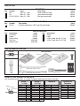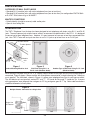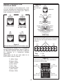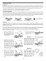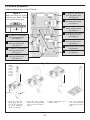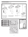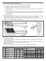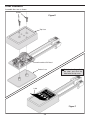
1
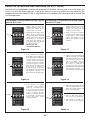
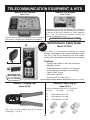
TELEPHONE LINE ANALYZER KIT
MODEL TWT-1K
Assembly and Instruction Manual
Elenco Electronics, Inc.
Copyright © 2001 Elenco Electronics, Inc.
753082
PARTS LIST
RESISTORS
Qty.
1
1
7
Symbol
R9
R4
R1-R3, R5-R8
Value
120W 5% 1/2W
560W 5% 1/2W
680W 5% 1/2W
Color Code
brown-red-brown-gold
green-blue-brown-gold
blue-gray-brown-gold
Part #
131201
135601
136801
SEMICONDUCTOR
Qty.
4
Symbol
D1-D4
Description
Bi-Color (Red/Green) LED (Light Emitting Diode)
Part #
350007
MISCELLANEOUS
Qty.
1
1
1
1
1
Description
PC Board
Solder
Battery Snap
Top Case
Bottom Case
Part #
519032
551135
590098
623124IC
623219IC
Qty.
2
1
1
1
Description
Screw
Label
4 Wire Cable with RJ-11 Plug
8 Wire Cable with RJ-45 Plug
Part #
643111
723017
920023
920024
PARTS IDENTIFICATION
Miscellaneous
Resistor
PC Board
Bottom Case
Top Case
Color bands show
resistor values
Semiconductor
Screw
4 Wire Cable with RJ-11 Plug
Label
Battery Snap
8 Wire Cable with RJ-45 Plug
LED
IDENTIFYING RESISTOR VALUES
Use the following information as a guide in properly identifying the value of resistors.
BAND 1
1st Digit
Bands
1 2 Multiplier
Tolerance
Color
Black
Brown
Red
Orange
Yellow
Green
Blue
Violet
Gray
White
Digit
0
1
2
3
4
5
6
7
8
9
BAND 2
2nd Digit
Color
Black
Brown
Red
Orange
Yellow
Green
Blue
Violet
Gray
White
Digit
0
1
2
3
4
5
6
7
8
9
-1-
Multiplier
Color
Black
Brown
Red
Orange
Yellow
Green
Blue
Silver
Gold
Multiplier
1
10
100
1,000
10,000
100,000
1,000,000
0.01
0.1
Resistance
Tolerance
Color
Silver
Gold
Brown
Red
Orange
Green
Blue
Violet
Tolerance
+/-10%
+/-5%
+/-1%
+/-2%
+/-3%
+/-.5%
+/-.25%
+/-.1%
SPECIFICATIONS
CATEGORY OF WALL PLATE JACKS
• Standard RJ-11 modular jacks with active telephone lines (one or two lines).
• Standard RJ-45 modular jacks with active telephone lines (one to four lines) for configuration EIA/TIA 568A
or B, AT&T 258A, token ring, or 10 BASE-T.
MULTIPLY FUNCTIONS
• Polarity identify (straight or reverse) cable and/or pairs.
• Open or short wiring test.
INTRODUCTION
The TWT-1 Telephone Line Analyzer has been designed to test telephone wall plates using RJ-11 and RJ-45
jacks. The most common jack used in homes, offices, or commercial establishments is the RJ-11. It is designed
to connect up to three telephone lines. However, it is most common to have one or two lines connected to the
jack. Your TWT-1 Tester will test up to two lines on an RJ-11 jack or up to four lines on an RJ-45 jack.
Line from outside
To other phones
Modular
Jack
Plug
Figure 1
Figure 2
Figure 3
Surface Mounting Modular Jack
Wall Plate Using RJ-11 or
RJ-45 Jacks (Modular Outlet)
Another Type of Wall Plate Using RJ-11 Jack
(Modular Outlet)
When testing a wall plate using an RJ-11 in a home, keep in mind that the single line may have multiple phones
connected. Figure 4 shows a home or office with three phones connected to a single incoming line. Note they
are in parallel. The 42A block, shown in Figure 4, is where your telephone lines start in your home or office.
The 42A block may have terminals marked “R”’ and ”‘T”. “R” stands for Ring and “T” stands for Tip. If correct
wiring procedures were followed, then red goes to “R” ring and green goes to “T” tip. Color code terminations
should be followed at all wall plates.
Figure 4
Multiple Phones Connected to a Single Line
R
Red
Single Line
To Protector
42A
T
Green
Wall
Desk
-2-
Wall
HOW IT WORKS
WIRING CONFIGURATION
for RJ-11 JACKS
The TWT-1 Analyzer is easy to use in quick testing
of the telephone lines. It will indicate by the color of
the LED if the wiring is correct, reversed or if it is not
working at all.
Figure 6
RJ-11-2
1
6
Typical color
scheme for one or
two lines.
1
Green
Green
Red
RJ-11-4
Yellow
Black
Red
6
Red
Green
Red
Green
Yellow
Black
RJ-11 Jack
RJ-11 Jack
One Phone Line
Two Phone Lines
Figure 7
Shows detail of how
the tip and ring are
connected on a four
connector cable.
+ = Tip
_ = Ring
Figure 5
It has four bi-colored LEDs that will light green or
red. LEDs 1 and 2 will respond to testing of an
RJ-11 jack having one or two lines. LEDs 1, 2, 3
and 4 will respond to testing of an RJ-45 jack
having one, two, three, or four lines using a wiring
scheme (see Figure 9).
Plug Polarities
PR2
PR1
O
P
E
N
O
P
E
N
1 2 3 4 5 6
Figure 8
Shows how the
phone wires relate
to the LEDs on the
analyzer for RJ-11.
Green LED is Lit - Indicates that the line
tested is operational and the wiring is correct.
PR 1
Wires 3 and 4
Red LED is Lit - Indicates that the wiring to
the jack is reversed. On some phones, it
would make the phone inoperative and would
require a reversal of the wires terminating at
the phone jack. On many new phones, the
phone circuitry recognizes this reversal and
corrects for it.
PR 2
Wires 2 and 5
When we refer to an RJ-11 plug and jack, we are
generally referring to a single or dual line plug and
jack. In the industry they may sometimes refer to an
RJ-11-2 as a single line jack and an RJ-11-4 as a
two line jack. Most modular jacks today are prewired with four wires and are suitable for one or two
lines. From the face of the wall plate, it is difficult to
tell if it’s wired for one or two lines.
No LED Lit - Indicates that the circuit is not
operational (open or shorted).
-3-
WIRING CONFIGURATIONS
FOR RJ-45 JACKS
Figure 10
Typical color
scheme for eight
lines.
The RJ-45 indicates an 8-wire plug or jack. There
are many standards which dictate which wire pairs
connect to which pins on a plug or jack. Some of
these standards are listed below.
1
Red
Green
Black
Yellow
Blue
Orange
EIA/TIA-568A
EIA/TIA 568B
or AT&T 258A
EIA/TIA-568A
8
Gray
Brown
Orange
Blue
Brown
Gray
Black
Red
Yellow
Green
RJ-45 Jack
Figure 11
Token Ring
Shows detail of how the tip and ring are connected on
a eight connector cable for EIA/TIA-568A standards
on Figure 9.
PR2
10 Base T
Figure 9
PR1
PR3
PR4
Different Wiring Standards for RJ-45 8-Wire Jacks
The telephone line analyzer TWT-1 is designed to
test the standard configurations shown in Figure 9.
The Electronic Industries Association established
this sequence as a “commercial building
specification”.
Shown below are the wire color codes for an
EIA/TIA-568A, shown in Figure 9.
1 2 3 4 5 6 7 8
+ = Tip
Plug
Polarities _ = Ring
Figure 12
T3 White / Green
R3 Green / White
T2 White / Orange
R1 Blue / White
T1 White / Blue
R2 Orange / White
T4 White / Brown
R4 Brown / White
Shows how the phone wires relate to the LEDs on
the analyzer for EIA/TIA-568A.
-4-
PR 1
Wires 4 and 5
PR 4
Wires 7 and 8
PR 2
Wires 3 and 6
PR 3
Wires 1 and 2
CONSTRUCTION
Introduction
Assembly of your TWT-1K Telephone Line Analyzer Kit will prove to be an exciting project and give you much satisfaction and personal
achievement. If you have experience in soldering and wiring techniques, then you should have no problem with the assembly of this kit. Care
must be given to identifying the proper components and in good soldering habits. Above all, take your time and follow these easy step-bystep instructions. Remember, “An ounce of prevention is worth a pound of cure”. Avoid making mistakes and no problems will occur.
CAUTION: WEAR SAFETY GLASSES WHEN ASSEMBLING THIS KIT.
Assemble Components
In all of the following assembly steps, the components must be installed on the top side of the PC board unless otherwise indicated. The
top legend shows where each component goes. The leads pass through the corresponding holes and the board is turned to solder the
component leads on the foil side. Solder immediately unless the pad is adjacent to another hole which will interfere with the placement
of the other component. Cut excessive leads with a diagonal cutter. Then, place a check mark in the box provided next to each step to
indicate that the step is completed. Be sure to save the extra leads for use as jumper wires if needed.
Foil Side
Rx - 100W 5% 1/4W Resistor
(brown-black-brown-gold)
Mount Part
Bend Leads to Hold Part
Solder and Cut Off Leads
Soldering
The most important factor in assembling your TWT-1K is good soldering techniques. Using the proper soldering iron is of prime
importance. A small pencil type soldering iron of 25 - 40 watts is recommended. The tip of the iron must be kept clean at all times
and well tinned. Many areas on the PC board are close together and care must be given not to form solder shorts. Size and care of
the tip will eliminate problems.
For a good soldering job, the areas being soldered must be heated sufficiently so that the solder flows freely. Apply the solder
simultaneously to the component lead and the component pad on the PC board so that good solder flow will occur. Be sure that the
lead extends through the solder smoothly indicating a good solder joint. Use only rosin core solder of 60/40 alloy.
DO NOT USE ACID CORE SOLDER! Do not blob the solder over the lead because this can result in a cold solder joint.
1.
Solder all components from
the copper foil side only.
Push the soldering iron tip
against both the lead and the
circuit board foil.
Soldering Iron
4.
Component Lead
Foil
Here is what a good solder
connection looks like. Cut
off excess leads.
Example 1
Circuit Board
2.
3.
First apply a small amount of
solder to the iron tip. This
allows the heat to leave the
iron and onto the foil.
Immediately apply solder to
the opposite side of the
connection, away from the
iron.
Allow the heated
component and the circuit
foil to melt the solder.
Allow the solder to flow
around the connection.
Then, remove the solder and
the iron and let the
connection cool. The solder
should have flowed smoothly
and not lump around the wire
lead.
Poor solder connections occur
when the lead is not heated
sufficiently. The solder will not
flow onto the lead as shown. To
correct. reheat the connection
and, if necessary, apply a small
amount of additional solder to
obtain a good connection.
Soldering Iron
Solder
Foil
Example 2
Solder
Soldering Iron
Foil
-5-
A solder bridge occurs when
solder runs between circuit
paths and creates a short
circuit. This is usually caused
by using too much solder. To
correct this, simply drag your
soldering iron across the
solder bridge as shown.
Solder does not flow onto the
lead. A hard rosin bead
surrounds and insulates the
connection.
Poor solder
connection
Soldering iron
positioned incorrectly.
PC BOARD ASSEMBLY
Solder the following parts to the PC board.
Figure A
R8 - 680W 5% ½W Resistor
(blue-gray-brown-gold)
(see Figure A)
Mount the resistor flat against
the PC board as shown. Solder
and cut off the excess leads.
R4 - 560W 5% ½W Resistor
(green-blue-brown-gold)
(see Figure A)
R9 - 120W 5% ½W Resistor
(brown-red-brown-gold)
(see Figure A)
Solder Side
R1 - 680W 5% ½W Resistor
(blue-gray-brown-gold)
(see Figure A)
R6 - 680W 5% ½W Resistor
(blue-gray-brown-gold)
(see Figure A)
R5 - 680W 5% ½W Resistor
(blue-gray-brown-gold)
(see Figure A)
R3 - 680W 5% ½W Resistor
(blue-gray-brown-gold)
(see Figure A)
8 Wire Cable with RJ-45 Plug
(see Figure B)
R7 - 680W 5% ½W Resistor
(blue-gray-brown-gold)
(see Figure A)
4 Wire Cable with RJ-11 Plug
(see Figure C)
R2 - 680W 5% ½W Resistor
(blue-gray-brown-gold)
(see Figure A)
Figure B
1
2
3
4
5
6
7
8
- Blue
- Orange
- Black
- Red
- Green
- Yellow
- Brown
- Gray
PC Board
1
8
Plug
1. Insert the cable with
RJ-45 plug into the
hole in the PC board
as shown, noting the
direction of the plug.
2. Insert the eight colored
wires into the corresponding
holes in the PC board as
shown.
3. Tug the cable down to the
position shown.
-6-
4. Turn the PC board
over. Solder the wires
and cut off the excess
leads.
PC BOARD ASSEMBLY
Solder the following parts to the PC board.
1
2
3
4
- Black
- Red
- Green
- Yellow
Figure C
1
4
PC Board
Plug
1. Insert the cable with
RJ-11 plug into the
hole in the PC board
as shown, noting the
direction of the plug.
2. Insert the four colored wires
into the corresponding holes
in the PC board as shown.
3. Tug the cable down to the
position shown.
4. Turn the PC board
over. Solder the wires
and cut off the excess
leads.
Figure D
D4 - Bi-Color LED
(see Figure D)
Mount the LED flat onto the PC
board with the flat side of the
LED in the same direction as
marked on the PC board.
Solder and cut off the excess
leads.
D1 - Bi-Color LED
(see Figure D)
D2 - Bi-Color LED
(see Figure D)
D3 - Bi-Color LED
(see Figure D)
Flat
-7-
TESTING AND TROUBLESHOOTING
1. One of the most frequently occurring problems is poor solder connections.
a) Tug slightly on all parts to make sure that they are indeed soldered.
b) All solder connections should be shiny. Resolder any that are not.
c) Solder should flow into a smooth puddle rather than a round ball. Resolder any connection that has
formed into a ball.
d) Have any solder bridges formed? A solder bridge may occur if you accidentally touch an adjacent foil
by using too much solder or by dragging the soldering iron across adjacent foils. Break the bridge with
your soldering iron.
2. Use a fresh 9V battery.
3. For all steps of testing (Tables 1 and 2), if the LED doesn’t light or more than one LED lights up, check for
bridges and open pads on the PC board, wires of the testing pair cable, and the testing LED.
If the color of the LED does not match with the color shown in the instructions, check orientation of the LED.
4. For testing, use a fresh 9V battery and battery snap.
Battery Snap
RJ-45
1
8
Red
1
4
RJ-11
Black
9V Battery
Figure 13
The following is the procedure for testing the PC board assembly and telephone line analyzer.
5. Test the RJ-11 connector.
Touch the red wire of the battery snap to pin 3 and the black wire to pin 2. The LED D3 of the PC board (#1
label) should light green.
Touch the red wire of the battery snap to pin 2 and the black wire to pin 3. The LED D3 (#1) should light red.
Check the other LED in the same manner and refer to Table 1 below.
6. Test the RJ-45 connector.
Check the RJ-45 connector in the same manner as the RJ-11 and refer to Table 2 below.
Table 1 RJ-11
Step Description
Table 2 RJ-45
PCB
LED
Label
Color
1
Red to pin 3
Black to pin 2
D3
#1
Green
2
Red to pin 2
Black to pin 3
D3
#1
Red
3
Red to pin 1
Black to pin 4
D2
#2
Green
4
Red to pin 4
Black to pin 1
D2
#2
Red
Step Description
1
2
3
4
5
6
7
8
-8-
Red
Red
Red
Red
Red
Red
Red
Red
to
to
to
to
to
to
to
to
pin
pin
pin
pin
pin
pin
pin
pin
5,
4,
3,
6,
1,
2,
7,
8,
Black
Black
Black
Black
Black
Black
Black
Black
to
to
to
to
to
to
to
to
pin
pin
pin
pin
pin
pin
pin
pin
4
5
6
3
2
1
8
7
PCB
LED
Label
Color
D3
D3
D2
D2
D1
D1
D4
D4
#1
#1
#2
#2
#3
#3
#4
#4
Green
Red
Green
Red
Green
Red
Green
Red
FINAL ASSEMBLY
Assemble the case as shown.
Screws
Figure E
Top Case
Assembled PC Board
Bottom Case
Peel the backing off of
the label and stick the
label onto the top case.
Label
Figure F
-9-
USING THE TELEPHONE LINE ANALYZER ON RJ-11 JACKS
Now that we have completed and tested the telephone line analyzer, you are ready to test wall plates that
have RJ-11 jacks with one or two lines. If wall plates with RJ-11 are not available, then you should use the
telephone line simulator Model TT-250. It will provide all of the conditions that would be found in the field and
are illustrated below.
The following is the procedure for testing a typical The following is the procedure for testing a typical
one line RJ-11 jack:
two line RJ-11 jack:
1. Remove the phone wire from
modular jack and insert
smaller telephone plug of
telephone line analyzer into
telephone jack to be tested.
Green
the
the
the
the
2. If the telephone line analyzer shows
LED 1 green, the telephone line
jack is working and it is wired with
straight polarity (see Figure 14).
The problem is in the telephone
cable going to the telephone or in
the telephone itself. The wiring in
the wall jack is correct.
DO NOT CALL THE
TELEPHONE COMPANY.
1. Remove the phone wire from
modular jack and insert
smaller telephone plug of
telephone line analyzer into
telephone jack to be tested.
1 and 2
Green
Figure 14
Red
2. LEDs 1 and 2 green (see Figure
17) indicates that both lines are
working and are wired straight
polarity. The problem is in the
cable going to the phone or in the
telephone.
Figure 17
3. If the telephone line analyzer
shows LED 1 red (see Figure 15),
the modular jack is working with
reversed polarity. The wires are
reversed. A dial tone should still
exist, but this may be a problem
for some touch phones. Plug the
phone back into the wall jack and
lift the receiver. If a dial tone is
present, but you do not get tones
when dialing, the wiring at the wall
jack should be corrected. See
technical data for wall jack wiring.
1 and 2
Red
3. LEDs 1 and 2 red (see Figure 18)
indicates both lines are working
with reversed polarity. The wires
are reversed on both lines and
may be a problem. Plug the
phone into the wall jack and lift
the receiver. If a dial tone is
present, but you do not get tones
when dialing, the wiring at the wall
jack should be corrected. See
technical data for wall jack wiring.
Figure 18
Figure 15
No Light
the
the
the
the
4. If the telephone line analyzer
shows LED 1 with no light (see
Figure 16), it indicates that the
line is open or wires are shorted.
Check the wall jack to make sure
a wire is not bent too far down,
broken, or touching another wire.
If the problem is not in the jack,
then you may need to call the
telephone company.
4. LED 1 green and LED 2 red (see
Figure 19) indicates that line 1 is
wired with straight polarity and
line 2 is reversed polarity.
1 Green
2 Red
5. LED 1 no light, LED 2 green or
red. Line one is not operational.
6. LED 1 green or red, LED 2 no
light. Line two is not operational.
Figure 19
Figure 16
-10-
USING THE TELEPHONE LINE ANALYZER ON RJ-45 JACKS
When testing an RJ-45 jack and there are two lines coming into the jack, two LEDs will be lit. If you have four
lines coming into the jack, four LEDs will be lit. If wall plates with RJ-45 jacks are not available, then you should
use the telephone line simulator Model TT-250. It will provide all of the conditions that would be found in the
field and are illustrated below.
Before testing, you should know which wiring standard is coming into the jack.
TIA-568B or
AT&T 258A
EIA/TIA-568A
Token Ring
Pair 1
Pair 1
Pair 1
Pair 2
Pair 3
Pair 2
Pair 3
Pair 2
Pair 4
Pair 4
10 Base T
Pair 2
Pair 1
Figure 20
The number pairs match with the number of LEDs on the label of the analyzer for EIA/TIA-568A and Token Ring
ONLY (see Figure 20).
The following is the procedure for testing RJ-45 jacks (for EIA/TIA-568A):
1. Remove the phone wire from the modular jack and insert the bigger telephone plug of the telephone line
analyzer into the telephone jack to be tested.
2. If the telephone line analyzer shows all green lights, the modular jack is working with straight polarity of all pairs.
3. If the telephone line analyzer shows all red lights, the modular jack is working with reverse polarity of all pairs.
4. If you have mixed colors of lights, or some lights are not lit, you may have a problem.
No light indicates an open pair, a pair not being used, or shorted wires.
5. For example, if LED 2 is not lit, but LEDs 1, 3 and 4 are green, line 2 (pair 2 for EIA/TIA-568A) is defective.
Pair 2 is wire 3 (T2 white / orange) and wire 6 (R2 orange / white).
-11-
LEARNING TO USE THE TWT-1 TELEPHONE LINE SIMULATOR MODEL TT-250
Elenco Electronics has developed a telephone line simulator, Model TT-250, for the TWT-1 Telephone Line
Analyzer. It will simulate the most common field situations. It provides an RJ-11 jack for one or two line testing,
straight and reversed wiring and simulates opens.
It also provides an RJ-45 jack for one, two, three, or four line testing, straight and reversed wiring and simulates opens.
Contact Elenco Electronics (800) 533-2441 for availability and price of the telephone line simulator Model TT-250.
A great teaching tool for the telecommunication field.
If the simulator Model TT-250 is not available for testing and troubleshooting the TWT-1, you can use the method
on page 8, or a wall plate that has a phone connected to it. Remove the telephone line plug from the wall plate.
Establish that it is an RJ-11 or RJ-45 type jack, and insert the correct plug into the wall plate. If you know that it
is a single line phone, number 1 on the line analyzer should be lit green. If it is lit red, the wires are reversed. The
phone could still work because the phone has a circuit built into it to reverse it to the proper polarity.
If you know where there are wall plates with more than one line coming in, then test that wall plate so that you
get familiar with normal readings.
DO NOT LEAVE THE TELEPHONE LINE ANALYZER IN THE JACK FOR ANY LENGTH OF TIME, AS THAT
LINE WILL GIVE A BUSY SIGNAL AND COULD OVERHEAT THE UNIT.
HOW THE CIRCUIT WORKS
SCHEMATIC DIAGRAM
The telephone line analyzer has four identical
indicators of polarity input voltage. Every indicator
includes two resistors and bi-color light emitting
diodes (LED), see Figure 21.
A
C Green
C
A Red
Ra
Rb
Figure 21
The operation of the bi-color LED is very simple. This
LED has two standard LEDs inside with red and
green colors. When voltage on the anode (A) of the
first single color LED is higher than the voltage on the
cathode (C), current flows through this LED and it will
emit light. At the same time, other single LEDs will
not light. After changing the polarity of the voltage,
the second LED will emit light.
The resistor Rb limits the current so that the LED will
not be damaged. The normal open telephone line
voltage between the tip and ring wires is 48VDC.
The resistors Ra and Rb divide an input voltage to a
lower voltage that the telephone line has when
connecting the telephone to the loop.
-12-
QUIZ
1. Solder is comprised of what two materials?
A. Gold and copper
B. Tin and lead
C. Zinc and copper
D. Lead and aluminum
6. Solder wick is used to . . .
A. remove solder.
B. solder in small parts.
C. cleaning the soldering iron tip.
D. removing flux.
2. What type of flux should be used in electronics?
A. Chloride
B. Organic
C. Rosin
D. Corrosive
7. A cold solder joint is caused by . . .
A. a solder bridge.
B. using 60/40 solder.
C. insufficient heat.
D. acid core solder.
3. When working on PC boards, what wattage range
of iron is ideal?
A. 25-40 watts
B. 50-100 watts
C. 1-10 watts
D. 100-200 watts
8. When two adjacent foils accidentally touch, it is
called . . .
A. a jumper.
B. a blob.
C. a solder hole.
D. a solder bridge.
4. Tinning the soldering tip will prevent it from . . .
A. heating.
B. melting.
C. soldering.
D. oxidizing.
9. What ratio has the greatest amount of tin?
A. 20/60
B. 40/60
C. 50/50
D. 60/40
5. Proper solder adhesion requires that the metal
surface to be . . .
A. solder free.
B. clean.
C. greasy.
D. cold.
10. A good solder connection should be . . .
A. dull and rough.
B. shiny, bright and smooth.
C. lumped around the connection.
D. soldered on one side of the connection.
Answers: 1. B, 2. C, 3. A, 4. D, 5. B, 6. A, 7. C, 8. D, 9. D, 10. B
-13-
TELECOMMUNICATION EQUIPMENT & KITS
Telephone Line Simulator
Telephone Line Analyzer
Model TT-250
Model TT-400
A telephone line analyzer that provides fast indication of
telephone line polarity, ring and line voltage levels, condition
of phone line from user’s telephone to central telephone
office - also can check basic telephone functions and
condition of telephone line cord.
Test and demonstrate the usage of the TWT-1 Telephone
Line Analyzer. Simulate typical telephone line problems.
Available Assembled Model TT-400K
Multi-Network Cable Tester
Vinyl Case Included
W
NE
Model TCT-255
This tester is a convenient instrument for testing
different unshielded wiring schemed telephone cables
with RJ-11 and RJ-45 connectors and coax cables.
Cables can be tested before and after they are installed.
Features:
•
•
•
•
•
•
•
Available as
Kit TCT-255K
Testing cables before or after their installation.
Mapping Function
Cable Identification (straight or cross-pinning)
Pair Identification (straight or cross-pinning)
Open or Short Testing
Low Battery Indicator
Auto Power-Off Function (30 s.)
Soft Vinyl Zippered Case (Model C-90) Included. (5 1/2” x 7” x 1 3/4”)
Modular Crimping Tool
Modular Cable Plug Kit
Model HT-568
Model MCP-5
Contains 30 modular plugs for RJ-11 and RJ-45.
10 - 6P4C
10 - 6P6C
10 - 8P8C
5 ft.
5 ft.
5 ft.
Cuts, strips, and crimps modular plugs RJ-45 and RJ-11.
Cushion grip. 7 1/2” long.
-14-
4 Wire Modular Flat Cable
6 Wire Modular Flat Cable
8 Wire Modular Flat Cable
WORD GLOSSARY
42A Block
A terminal block that provides telephone line junctions.
Anode
The positive terminal of a diode or other polarized component.
Bi-Color LED
A component that combines two dice of different colors upon a single substrate or lead-frame
carrier.
Cathode
The negative terminal of a diode or other electronic component.
Current
Transport of electrons through a conductor and measured in amps.
Dial Tone
A 350 and 440 hertz tone that is imposed on the line when the phone is first taken off the hook.
Diode
An electronic component that rectifies AC to DC. Used for signal detection.
E.I.A. Standard T568A
The Electronic Industries Association established this sequence as a “commercial building
specification”.
E.I.A. Standard
T568B or AT&T 258A
Designed for data transmission.
FCC
Federal Communications Commission. A U.S. Government agency that regulates and monitors
the domestic use of the electromagnetic spectrum for communications.
Ground
An electrical connection to the earth of the a common conductor which is connected to the earth.
Hertz
The basic unit for frequency or cycles per second.
LED
(Light Emitting Diode) A semiconductor diode emitting incoherent light at its P-N junction when
forward biased.
Modular Cable
A telephone cable with modular plugs used to connect phones or devices to the system.
Modular Jack
The female connector of a telephone outlet.
Modular Plug
The male connector that plugs into a modular jack.
PC Board
Printed Circuit Board that has copper traces for conducting circuits to components.
Polarity
Refers to positive (+) and negative (–) poles of a voltage source.
Positive
The plus (+) pole of a battery DC supply or other polarity-sensitive item.
Pulse
A short signal.
Ring
The name of one conductor of a telephone line pair, identified by R. Most often the red wire and
the most negative of the two wires.
RJ-11
A designation given to modular plugs and jacks capable of handling 1 to 3 phone lines.
RJ-45
A designation given to modular plugs and jacks, similar to an RJ-11, but larger and capable of
handling 1 to 4 lines.
TelCo
Abbreviation for telephone company.
Tip
The name of one conductor of a telephone line pair, identified by T. Most often the green wire and
the most positive of the two wires.
USOC
A universal service code derived from Bell System specifications.
USOC 4
Refers to two pairs or lines on an RJ-11 jack.
Voltage
Electrical potential difference measured in volts.
Elenco Electronics, Inc.
150 W. Carpenter Avenue
Wheeling, IL 60090
(847) 541-3800
http://www.elenco.com
e-mail: [email protected]