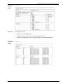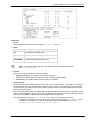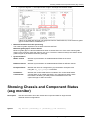
1
Check Point 61000 Security System Getting Started Guide 8 November 2011 © 2011 Check Point Software Technologies Ltd. All rights reserved. This product and related documentation are protected by copyright and distributed under licensing restricting their use, copying, distribution, and decompilation. No part of this product or related documentation may be reproduced in any form or by any means without prior written authorization of Check Point. While every precaution has been taken in the preparation of this book, Check Point assumes no responsibility for errors or omissions. This publication and features described herein are subject to change without notice. RESTRICTED RIGHTS LEGEND: Use, duplication, or disclosure by the government is subject to restrictions as set forth in subparagraph (c)(1)(ii) of the Rights in Technical Data and Computer Software clause at DFARS 252.227-7013 and FAR 52.227-19. TRADEMARKS: Refer to the Copyright page (http://www.checkpoint.com/copyright.html) for a list of our trademarks. Refer to the Third Party copyright notices (http://www.checkpoint.com/3rd_party_copyright.html) for a list of relevant copyrights and third-party licenses. Important Information Latest Software We recommend that you install the most recent software release to stay up-to-date with the latest functional improvements, stability fixes, security enhancements and protection against new and evolving attacks. Latest Documentation The latest version of this document is at: http://supportcontent.checkpoint.com/documentation_download?ID=12557 For additional technical information, visit the Check Point Support Center (http://supportcenter.checkpoint.com). Revision History Date Description 08-Nov-11 First release of this document Feedback Check Point is engaged in a continuous effort to improve its documentation. Please help us by sending your comments (mailto:[email protected]?subject=Feedback on Check Point 61000 Security System Getting Started Guide). Health and Safety Information Read the these warnings before setting up or using the appliance. Warning Do not block air vents. This is to ensure sufficient airflow for the individual SGMs in the chassis. This appliance does not contain any user-serviceable parts. Do not remove any covers or attempt to gain access to the inside of the product. Opening the device or modifying it in any way has the risk of personal injury and will void your warranty. The following instructions are for trained service personnel only. Handle SGM system parts carefully to prevent damage. These measures are sufficient to protect your equipment from static electricity discharge: When handling components (Fans, CMMS, SGMS, PSUs, SSMs) use a grounded wrist-strap designed for static discharge elimination. Touch a grounded metal object before removing the board from the antistatic bag. Hold the board by its edges only. Do not touch its components, peripheral chips, memory modules or gold contacts. When holding memory modules, do not touch their pins or gold edge fingers. Restore SGMs to the anti-static bag when they are not in use or not installed in the chassis. Some circuitry on the SGM can continue operating after the power is switched off. Do not let the lithium battery cell (used to power the real-time clock on the CMM) short. The battery can heat up and become a burn hazard. Warning - DANGER OF EXPLOSION IF BATTERY IS INCORRECTLY REPLACED. REPLACE ONLY WITH SAME OR EQUIVALENT TYPE RECOMMENDED BY CHECK POINT SUPPORT. DISCARD USED BATTERIES ACCORDING TO INSTRUCTIONS FROM CHECK POINT. Do not operate the processor without a thermal solution. Damage to the processor can occur in seconds. For California: Perchlorate Material - special handling can apply. See http://www.dtsc.ca.gov/hazardouswaste/perchlorate The foregoing notice is provided in accordance with California Code of Regulations Title 22, Division 4.5, Chapter 33. Best Management Practices for Perchlorate Materials. This product, part, or both may include a lithium manganese dioxide battery which contains a perchlorate substance. Proposition 65 Chemical Chemicals identified by the State of California, pursuant to the requirements of the California Safe Drinking Water and Toxic Enforcement Act of 1986, California Health & Safety Code s. 25249.5, et seq. ("Proposition 65"), that is "known to the State to cause cancer or reproductive toxicity" (see http://www.calepa.ca.gov) WARNING: Handling the cord on this product will expose you to lead, a chemical known to the State of California to cause cancer, and birth defects or other reproductive harm. Wash hands after handling. Federal Communications Commission (FCC) Statement: Note: This equipment has been tested and found to comply with the limits for a Class A digital device, pursuant to Part 15 of the FCC Rules. These limits are designed to provide reasonable protection against harmful interference when the equipment is operated in a commercial environment. This equipment generates, uses, and can radiate radio frequency energy and, if not installed and used in accordance with the instruction manual, may cause harmful interference to radio communications. Operation of this equipment in a residential area is likely to cause harmful interference in which case the user will be required to correct the interference at his own expense. Information to user: The user's manual or instruction manual for an intentional or unintentional radiator shall caution the user that changes or modifications not expressly approved by the party responsible for compliance could void the user's authority to operate the equipment. In cases where the manual is provided only in a form other than paper, such as on a computer disk or over the Internet, the information required by this section may be included in the manual in that alternative form, provided the user can reasonably be expected to have the capability to access information in that form. Canadian Department Compliance Statement: This Class A digital apparatus complies with Canadian ICES-003. Cet appareil numérique de la classe A est conforme à la norme NMB-003 du Canada. Japan Class A Compliance Statement: European Union (EU) Electromagnetic Compatibility Directive This product is herewith confirmed to comply with the requirements set out in the Council Directive on the Approximation of the Laws of the Member States relating to Electromagnetic Compatibility Directive (2004/108/EC). This product is in conformity with Low Voltage Directive 2006/95/EC, and complies with the requirements in the Council Directive 2006/95/EC relating to electrical equipment designed for use within certain voltage limits and the Amendment Directive 93/68/EEC. Product Disposal This symbol on the product or on its packaging indicates that this product must not be disposed of with your other household waste. Instead, it is your responsibility to dispose of your waste equipment by handing it over to a designated collection point for the recycling of waste electrical and electronic equipment. The separate collection and recycling of your waste equipment at the time of disposal will help to conserve natural resources and ensure that it is recycled in a manner that protects human health and the environment. For more information about where you can drop off your waste equipment for recycling, please contact your local city office or your household waste disposal service. Contents Important Information .............................................................................................3 Health and Safety Information ...............................................................................3 Introduction .............................................................................................................7 Overview of Check Point 61000 Security Systems .............................................. 7 In this Document ................................................................................................. 8 Shipping Carton Contents.................................................................................... 8 Hardware Components ...........................................................................................9 61000 Security System Front Panel Modules ...................................................... 9 Security Switch Module Ports .............................................................................11 SSM60 Security Switch Module .....................................................................11 SSM160 Security Switch Module ...................................................................12 AC Power Supply Units (PSUs) ..........................................................................13 Fan Trays ...........................................................................................................14 Chassis Management Modules...........................................................................14 Blank Filler Panels for Airflow Management .......................................................16 Front Blank Panels with Air Baffles ................................................................16 Step 1: Site Preparation........................................................................................17 Rack Mounting Requirements ............................................................................17 Required Tools ...................................................................................................17 Step 2: Installing the Device in a Rack ................................................................18 Step 3: Installing Components and Connecting Power Cables .........................18 Inserting Power Supply Units ..............................................................................19 Inserting Fan Trays.............................................................................................19 Inserting Chassis Management Modules ............................................................21 Inserting Security Switch Modules ......................................................................22 Inserting Security Gateway Modules ..................................................................23 Inserting Transceivers ........................................................................................24 Inserting Twisted Pair Transceivers ...............................................................24 Inserting Fiber Optic Transceivers .................................................................25 Inserting QSFP Splitters ................................................................................26 Inserting Front Blank Panels ...............................................................................26 Connecting a Second Chassis ............................................................................26 Connecting Power Cables ..................................................................................27 Step 4: Powering Up .............................................................................................27 Step 5: Initial Software Configuration .................................................................28 Connecting a Management Console ...................................................................28 Performing the Initial Setup ................................................................................28 Step 6: Installing the Security Policy...................................................................30 Confirming the Software Configuration ...............................................................31 Basic Configuration Using gclish ........................................................................32 Licensing and Registration ..................................................................................33 Monitoring and Configuration Commands..........................................................34 Showing Chassis and Component State (asg stat) .............................................34 Showing Chassis and Component Status (asg monitor) .....................................37 Monitoring Key Performance Indicators and Load Statistics (asg perf) ...............39 Showing Hardware Information for Monitored Components (asg hw_monitor)....41 Showing Security Gateway Module Resource Information (asg resource) ..........43 Searching for a Connection (asg search)............................................................45 Configuring Alerts for SGM and Chassis Events (asg alert) ................................46 Overview of Check Point 61000 Security Systems Introduction Thank you for choosing Check Point’s 61000 Security System. We hope that you will be satisfied with this system and our support services. Check Point products supply your business with the most up to date and secure solutions available today. Check Point also delivers worldwide technical services including educational, professional and support services through a network of Authorized Training Centers, Certified Support Partners and Check Point technical support personnel to ensure that you get the most out of your security investment. For additional information on the Internet Security Product Suite and other security solutions, refer to the Check Point Web site (http://www.checkpoint.com), or call Check Point at 1(800) 429-4391. For additional technical information about Check Point products, consult the Check Point Support Center (http://supportcenter.checkpoint.com). Welcome to the Check Point family. We look forward to meeting all of your current and future network, application and management security needs. Overview of Check Point 61000 Security Systems The Check Point 61000 Security System is a high performance, scalable, carrier class solution for Service Providers and high-end data centers. The system gives advanced services such as Firewall, IPS, URL Filtering, Anti-Virus, Encryption and other Security Gateway Software Blade functionality to meet your dynamically changing security needs. The Check Point 61000 Security System is a 14-15U chassis and includes: Component(s) Function Up to 12 Security Gateway Modules (SGMs) Runs a high performance Firewall, and other Software Blades. Up to 2 Security Switch Modules (SSMs) Distributes network traffic to SGMs. Up to 2 Chassis Management Modules (CMMs) Monitors the chassis, the SSMs and the SGMs with zero downtime. The 61000 Security System: Is highly fault tolerant, and provides redundancy between chassis modules, power supplies and fans. Install a second chassis for more redundancy. Has NEBS and Non-NEBS certified versions. The Network Equipment Building Systems (NEBS) certificate ensures that 61000 Security System meets the environmental and spatial requirements for products used in telecommunications networks. Includes a rich variety of CLI monitoring and management tools. The system can be centrally managed from Check Point Security Management server or a Multi-Domain Security Management. Lets you Install different combinations of SGMs, SSMs and CMMs to match the processing needs of your network. Introduction Page 7 In this Document In this Document A brief overview of necessary 61000 Security System concepts and features A step by step guide to getting the 61000 Security System up and running Note - Screen shots in this guide may apply only to the highest model to which this guide applies. Shipping Carton Contents This section describes the contents of the shipping carton. Item Description Check Point 61000 Security System A single 61000 Security System chassis 61000 Security System components 2 to 12 Security Gateway Modules 2 Security Switch Modules 1 or 2 Chassis Management Modules Power Supplies Documentation 5 AC Power Supply Units (PSUs) or 1 to 2 DC Power Entry Modules (PEMs) 6 Fans (preinstalled) EULA Welcome document Obligatory Hardware Purchases Transceivers are not included in the shipping carton and must be purchased separately. SSM60 Transceivers Ports Required Transceivers Network and Synchronization Fiber transceiver for 10GbE XFP ports (SR/LR) Management and log Fiber transceiver for 1GbE SFP ports (SR/LR) Twisted-pair transceiver for 1GbE SFP ports Fiber transceiver for 10GbE XFP ports (SR/LR) SSM160 Transceivers Ports Required Transceivers Network and Synchronization Fiber transceiver for 10GbE SFP+ ports (SR/LR) Twisted-pair transceiver for 10GbE SFP+ ports QSFP transceiver for 40GbE ports (SR) QSFP splitter for 40GbE ports Fiber/Twisted pair transceiver for 1GbE SFP+ ports (SR/LR) Fiber transceiver for 10GbE SFP+ ports (SR/LR) Management and log Introduction Page 8 61000 Security System Front Panel Modules Hardware Components This sections covers hardware components of the 61000 Security System 61000 Security System Front Panel Modules Item Description 1 The Security Gateway Modules (SGMs) in the chassis work together as a single, high performance Security Gateway. Adding a Security Gateway Module scales the performance of the system. A Security Gateway Module can be added and removed without losing connections. If an SGM is removed or fails, traffic is distributed to the other active SGMs. Security Gateway Module slots are numbered 1 to 12, left to right. Slot 7 for example, (labeled [7] in the diagram) is the slot that is immediately to the right of the two Security Switch Module slots. 2 Console port, for a serial connection to a specific SGM using a terminal emulation program. Hardware Components Page 9 61000 Security System Front Panel Modules Item Description 3 The Security Switch Module (SSM) distributes network traffic to the Security Gateway Modules and forwards traffic from the Security Gateway Modules. One or two can be inserted in a chassis. Two SSM versions are available: SSM60 SSM160 For more about each port, see Security Switch Module Ports (on page 11). 4 The Chassis Management Module (CMM) monitors the status of the chassis hardware components. If the Chassis Management Module fails or is removed from the chassis, the 61000 Security System continues to forward traffic. However, hardware monitoring is not available. Adding or removing an Security Gateway Module to or from the chassis is not recognized. A second Chassis Management Module can be used to supply CMM High Availability. In the CLI output, the lower slot is listed bay 1. The upper slot is listed as bay2. 5 Power: AC Power Supply Units (PSUs) 100 VAC to 240 VAC 3-5 PSUs (minimum of 3 recommended) Or: DC Power Entry Modules (PEMs) 48 VDC to 60 VDC 1-2 PEMs Field-replaceable and hot-swappable In the CLI output: Upper slots are listed as bay 1, bay 2 and bay 3, numbered right to left. The lower slots are listed as bay4, bay 5 and bay 6, numbered right to left. Hardware Components Page 10 Security Switch Module Ports Security Switch Module Ports The Security Switch Module (SSM) distributes network traffic to the Security Gateway Modules and forwards traffic from the Security Gateway Modules. One or two can be inserted in a chassis. Two SSM versions are available: SSM60 SSM160 SSM60 Security Switch Module Security Switch Modules Item (1) 5 x 10GbE XFP data ports in each Security Switch Module. These data ports are the network interfaces of the 61000 Security System. In the initial setup program, the interfaces in the Left Security Switch Module are named: eth1-01, eth1-02, ... eth1-05 Right Security Switch Module are named: eth2-01, eth2-02, ... eth2-05 In SmartDashboard, define used interfaces as internal or external. (2) 1 synchronization port on each SSM for connecting to and synchronizing with another 61000 Security System that functions as a high availability peer. (3) 4 ports for management and logging on each SSM. 2 Upper ports: 1GbE SFP 2 Lower ports: 10GbE XFP Connect these ports to the management/logging network. Security Management server or dedicated logging servers should be accessible from these interfaces. In the initial setup program, the interfaces are named: On Left SSM: eth1-Mgmt1, eth1-Mgmt2, ... eth1-Mgmt4 On the right SSM: eth2-Mgmt1, eth2-Mgmt2, ... eth2-Mgmt4 Hardware Components Page 11 Security Switch Module Ports SSM160 Security Switch Module Security Switch Modules Item Description (1) 1 port for direct access through LAN 1 port for direct access through console (serial) 2 QSFP data ports 40GbE, can split to 4 x 10GbE using a QSFP splitter 7 data ports 10GbE SFP+ ports Can use 1GbE or 10GbE transceivers In the initial setup program, the interfaces in the (2) (3) (4) (5) (6) Left Security Switch Module are named: eth1-01, eth1-02, ... eth1-07 Right Security Switch Module are named: eth2-01, eth2-02, ... eth2-07 In SmartDashboard, define used interfaces as internal or external. 1 synchronization port for connecting to and synchronizing with another 61000 appliance that functions as a high availability peer. 10 GbE SFP+ ports Management and logging ports. Connect these ports to the management/logging network. Security Management server or dedicated logging servers should be accessible from these interfaces. 2 10GbE SFP+ ports In the 61000 appliance initial setup program, these interfaces are labeled: On the left SSM: eth1-Mgmt1, eth1-Mgmt2 On the right SSM: eth2-Mgmt1, eth2-Mgmt2 Management and logging ports. Connect these ports to the management/logging network. Security Management server or dedicated logging servers should be accessible from these interfaces. 1GbE SFP+ ports In the 61000 appliance initial setup program, these interface are labeled On the left SSM: eth1-Mgmt3, eth1-Mgmt4 On the right SSM: eth2-Mgmt3, eth2-Mgmt4 Hardware Components Page 12 AC Power Supply Units (PSUs) AC Power Supply Units (PSUs) 5 Field replaceable and hot swappable PSUs provide: Power to the chassis Power filtering and over-current protection. Each PSU is located on a tray that slides directly into the backplane. Item Description (AC Power Unit) 1 Tumble screw 2 Power Supply LEDs: AC OK. Normally green. Red means AC is missing DC OK. Normally green. Red means that the DC is missing H SWAP. Normally blue. The unit can be hot-swapped. 3 Extraction lever 4 Air filter Note - The 61000 Security System is also available with 1-2 DC Power Entry Modules (PEMs). Hardware Components Page 13 Fan Trays Fan Trays The cooling system consists of three high performance fan trays. Each tray contains two fans that supply air volume and velocity for cooling front and rear chassis components. Air flows from the inside to the outside of the chassis. Item Description 1 Power fault LED 2 Locking captive screw Three fan trays are preinstalled (6 fans). Chassis Management Modules The Chassis Management Module controls and manages the chassis. Amongst other activities, the CMM controls fan speeds, monitors temperatures across the chassis, and the hot-swap insertion and extraction of components. Item Description 1 General LEDs 2 Telco Alarm LEDs 3 Application defined LEDs 4 Latch Hardware Components Page 14 Chassis Management Modules Item Description 5 Network port 6 Serial port 7 Alarm 8 Tumble screw General LEDs LED Status Meaning ACT Green Chassis Management Module is active Red Chassis Management Module failure Green blink Chassis Management Module inactive Green Good local voltage supply on Chassis Management Module Off Local voltage failure Steady blue Chassis Management Module is powering up or ready for extraction. Blue blink Chassis Management Module is being hot swapped Off Chassis Management Module in operation PWR HS (hot swap) Telco Alarm LEDs LED Status Meaning CRT (Critical) Off Normal operation Red System alarm event Off Normal operation Red System Alarm event Off Normal operation Red System alarm event MJR (Major) MNR (Minor) Hardware Components Page 15 Blank Filler Panels for Airflow Management Blank Filler Panels for Airflow Management Compliance with temperature specifications requires a stable air flow in the chassis. To make sure that the chassis is correctly cooled, fully populate the chassis or add blank filler panels to the empty slots. Two types of airflow-management panels are available for the empty slots on the chassis: Front blank panels with air baffles Rear panel with air baffles Front Blank Panels with Air Baffles Item Description 1 Slot cover 2 Tightening screws 3 Air Baffles Hardware Components Page 16 Rack Mounting Requirements Step 1: Site Preparation This step covers preparing the site. Rack Mounting Requirements Before mounting the 61000 Security System in a standard 19" rack, make sure that: The rack is stable, level, and secured to the building. The rack is sufficiently strong to support the weight of a fully loaded Security System (http://www.checkpoint.com/products/downloads/datasheets/61000-security-system-datasheet.pdf). The rack rails are spaced sufficiently wide to accommodate the system's external dimensions. The shelf is mounted on the rack. There is sufficient space at the front and rear of the chassis to let service personnel to swap out hardware components. The rack has a sufficient supply of cooling air. The rack is correctly grounded. A readily accessible disconnect device is incorporated into the building’s wiring. The disconnect device must be placed between the system's AC power inlet and the power source. The disconnect device rating required must be determined by the nominal input voltage. There are at least two inches of clearance at the air inlets and outlets to make sure there is sufficient airflow. Hot exhaust air is not circulated back into the system. At least two persons are available to lift the chassis. You have eight M6x10 (or longer) screws to mount the chassis on the rack. Required Tools To install the appliance in a standard 19" rack, these tools are required: Standard Philips (+) screwdriver set Wrench Electrostatic Discharge (ESD) grounding wrist strap Step 1: Site Preparation Page 17 Required Tools Step 2: Installing the Device in a Rack Before mounting on rack Insert the: AC PSUs or DC PEMs Fan Units Attach the rear-end static grounding screws to the chassis. To install the Chassis on the Rack: 1. Set the chassis in front of the rack, centering the chassis in front the shelf. 2. Lift and slide the chassis on to the rack shelf. 3. Make sure that the holes in the front mounting flanges of the chassis align with the holes in the rack rails. 4. Insert mounting screws into the front mounting flanges aligned with the rack. 5. Secure the appliance by fastening the mounting screws to the rack The appliance must be level, and not positioned at an angle. 6. Attach grounding cables to the grounding screws on the chassis. Step 3: Installing Components and Connecting Power Cables This section covers inserting: One or more Chassis Management Modules One or more Security Switch Modules Security Gateway Modules Twisted pair and fiber optic transceivers into ports on the Security Switch Modules Transceivers into the management ports on the Security Switch Modules Covers for blank slots This section also covers: Backup chassis in a dual chassis environment Power cables Step 2: Installing the Device in a Rack Page 18 Inserting Power Supply Units Inserting Power Supply Units Power Supply Units (AC only) are inserted at the front of the chassis. If you have one Power Supply Unit already in place, other units can be swapped in and out without interfering with the operation of the 61000 Security System. Note that one PSU cannot supply sufficient power to support a fully populated chassis. To Insert a Power Supply Unit: 1. 2. 3. 4. Pull out the lever. Push in the Power Supply. Push in the Power Supply insertion lever. Make sure that the Power Supply LEDs light up: AC and DC LEDs show green HS LED remains unlit 5. Tighten the two tumble screws. Inserting Fan Trays When a fan tray is inserted into the chassis, the fans start at full speed and then decrease by steps of 7%. Under normal operating conditions, the fans run at 21% of full speed. The lower speed reduces the noise and increases the longevity of the fans. The speed of each individual fan is monitored. If the speed of one fan drops below the desired speed (i.e. fan failure) , the other fans speed up. Step 3: Installing Components and Connecting Power Cables Page 19 Inserting Fan Trays Fans are pre-installed in the appliance. Manual replacement must be coordinated with Check Point Support. To Insert a Fan: 1. Slide the fan into the allocated space. 2. Tighten the locking captive screw. Step 3: Installing Components and Connecting Power Cables Page 20 Inserting Chassis Management Modules Inserting Chassis Management Modules To insert a Chassis Management Module: 1. Open the latch at the top 2. Insert the Chassis Management Module into the allocated slot. Note - If you have only one CMM, we recommend inserting it into the lower chassis slot 3. Fasten the latch. 4. Close the two tumble screws tightly. 5. After power up, all LEDs must light up for 1-2 seconds. The ACT and PWR LEDs continue to show green after the other LEDs turn off. Step 3: Installing Components and Connecting Power Cables Page 21 Inserting Security Switch Modules Inserting Security Switch Modules To insert a Security Switch Module: 1. 2. 3. 4. Open the latches at the top and bottom of the Security Switch Module. Slide the SSM into the allocated slot. Fasten the latches. Tighten the screws. Step 3: Installing Components and Connecting Power Cables Page 22 Inserting Security Gateway Modules Inserting Security Gateway Modules To insert a Security Gateway Module: 1. 2. 3. 4. 5. Open the latches at the top and bottom of the Security Gateway Module. Make sure the SGM is located correctly on the chassis rail. Slide the Security Gateway Module into the allocated slot. Fasten the latches. Tighten the tumble screws. Step 3: Installing Components and Connecting Power Cables Page 23 Inserting Transceivers Inserting Transceivers For connecting different interface types to the 61000 Security System using SFP, SFP+, or XFP ports on the SSM, Security Switch Modules support Twisted Pair and Fiber Optic transceivers. The type and number of transceiver ports available depends on the SSM. Note - Remember to select a transceiver that matches the speed of the designated port. Inserting Twisted Pair Transceivers Twisted pair transceivers can be inserted into: Data and management ports on the SSM160 Step 3: Installing Components and Connecting Power Cables Page 24 Inserting Transceivers SFP management ports on the SSM60 Slide the transceiver into the open Security Switch Module port. Inserting Fiber Optic Transceivers Fiber transceivers can be inserted into data and management ports on the SSM60 and SSM160 switch modules. The ports can be SFP, SFP+ or XFP. Slide the transceiver into the open Security Switch Module port. Step 3: Installing Components and Connecting Power Cables Page 25 Inserting Front Blank Panels Inserting QSFP Splitters 1. Insert the QSFP transceiver into the Security Switch Module. 2. Insert the QSFP splitter cable into the transceiver. This converts the 40GbE QSPF port to 4 10GbE ports. Inserting Front Blank Panels Blank panels contain cooled air in the appliance. Use the blank panels to close open slots. To Insert a blank Panel at the front: 1. Insert the blank panel into the open slot. 2. Tighten the two tumble screws. Note - Rear blank panels are pre-installed on the chassis. Connecting a Second Chassis If you have a dual chassis environment (for chassis high availability): For the second chassis, repeat steps 1-3 Connect the second chassis On each SSM, connect the sync ports to the same sync ports on the backup chassis. Step 3: Installing Components and Connecting Power Cables Page 26 Connecting Power Cables Connecting Power Cables Connect power cables at the rear: Step 4: Powering Up Connect the appliance to the power source. At power up: Fan speed goes to maximum. LEDs on the Chassis Management Module light up. After 1-60 seconds, fan speed slows down until it reaches the optimum rate for cooling. Chassis Management Module ACT and PWR LEDs show green. Other LEDs turn off. Step 4: Powering Up Page 27 Connecting a Management Console Step 5: Initial Software Configuration When installing and configuring the 61000 Security System, start with the Security Gateway Module furthest to the left in the chassis. After the first SGM is configured, installation and configuration settings are automatically propagated to all other SGMs in the defined security group. The Security Group is the group of SGMs that make up the Security Gateway. Note - In SmartDashboard, one Security Gateway object represents the SGMs in the security group. Connecting a Management Console 1. Connect the RJ-45 jack end of a serial cable to the console port on the left-most Security Gateway Module in the chassis. 2. Connect the other end of the serial cable to the computer that you will use to do the initial configuration of the 61000 Security System. 3. On the configuration computer, connect to the 61000 Security System using a terminal emulation application such as PuTTY. Make sure the Speed (baud rate) is set to 9600 No IP address is necessary 4. Log in with username: admin and password: admin. Performing the Initial Setup 1. To start the installation wizard run #setup 2. In the Welcome screen, press a key. 3. Select Set SGMs for Security Group Step 5: Initial Software Configuration Page 28 Performing the Initial Setup 4. Define the SGMs that belong to the Security Group. There are two lines, one for Chassis 1, one for chassis 2. In each line, you can enter: all (same as 1-12) A range, such as: 1-9 A number of comma-separated ranges, such as: 1-3,5-7 Single SGMS, such as: 1,4 A combination of single SGMs and ranges, such as: 10,2, 3-7. By default, the SGM you are connected belongs to the group: Chassis 1, SGM 1 (slot 1 in chassis 1). To define a fully populated dual chassis system select all in the top and bottom lines. For more about Security Gateway Module numbering, see 61000 Security System front panel components ("61000 Security System Front Panel Modules" on page 9). 5. The subnet for internal communication in the chassis is 192.0.2.0/24 by default. Change the IP address if it conflicts with an existing subnet on your network. 6. Configure parameters for: Host Name Time and Date. To configure the local time, choose the geographical area and city. 7. Select Network Connections. Configure the management ports and the data ports of the Security Switch Module. There are 4 management ports on each SSM. Only configure those ports you intend to use. To associate port names with the physical ports, refer to Security Switch Module Ports (on page 11). For each management port configure: An IP address The Netmask length To associate data port names with the physical ports, refer to Security Switch Module Ports (on page 11). For each data port configure: An IP address The Netmask length 8. Configure Routing. Note - Wait 10-20 seconds for routing information to be updated throughout the system. 9. The Welcome to Check Point Suite screen shows. Wait for Check Point products packages to install, such as Performance Pack. 10. Wait for the: Installation Program Completed Successfully message to show Check Point Configuration Program to start. This program guides you through the configuration of Check Point products. 11. Configure Secure Internal Communication. When prompted, enter and confirm the activation key. Remember this activation key. The same activation key is used for configuring the 61000 Security System object in SmartDashboard. Configuration settings are applied, and the SGM reboots. The other Security Gateway Modules in the security group install automatically. Step 5: Initial Software Configuration Page 29 Performing the Initial Setup System Validation Make sure that the initial system setup completed successfully by: Running the asg monitor command. An initial policy must be installed on the local SGM after initial setup completes and the SGM reboots. To monitor the automatic installation of other SGMs, run: tail -f /var/log/start_mbs.log. After installation, all the SGMs in the security group must be in the Initial Policy state. Step 6: Installing the Security Policy Connecting to the Network 1. Connect the management ports on the Security Switch Modules to your network. 2. Connect the data ports on the Security Switch Modules to your network. Creating an Object in SmartDashboard The Check Point Security Gateway Creation Wizard is version dependent. The steps shown apply to R75. 1. Open SmartDashboard (R75 and above). 2. Enter your credentials to connect to the Security Management server. 3. Create the Check Point Security Gateway object. In the Network Objects tree, right click and select New > Check Point > Security Gateway/Management The Check Point Security Gateway Creation wizard opens. 4. Select Wizard Mode or Classic Mode. This procedure describes Wizard mode. If you choose Classic Mode, make sure you set all the necessary configuration parameters. 5. In the General Properties screen, configure: 6. 7. 8. 9. 10. 11. 12. Gateway name Gateway platform - Select Open server Gateway IP address Click Next. In the Secure Internal Communication Initialization screen, enter the One-time password. This is the same as the Activation Key you entered during the initial setup. Click Next. View the Configuration Summary. Select Edit Gateway properties for further configuration. Click Finish. The General Properties page of the 61000 Security System object opens. In the General Properties page, make sure the Version is correct. Step 6: Installing the Security Policy Page 30 Confirming the Software Configuration 13. Enable the Firewall Software Blade. If required, enable other supported Software Blades. 14. In the navigation tree, select Topology. 15. Configure: Interfaces as Internal or External Anti-Spoofing. Note: Only data and management interfaces are shown in the list. 16. Click OK. The Security Gateway object closes. 17. Install the Policy. Confirming the Software Configuration To make sure that the policy was successfully installed: 1. Connect to the appliance (through ssh or the serial console). 2. Run asg monitor. 3. Make sure that the status for SGMs is: Enforcing Security on the ACTIVE and STANDBY chassis. 4. Make sure the Policy Date matches the time that the policy was installed. Step 6: Installing the Security Policy Page 31 Confirming the Software Configuration Basic Configuration Using gclish Use the gclish shell for basic system configuration. To: Run Set an IPv4 address on an interface # set interface eth1-01 ipv4-address 50.50.50.10 mask-length 24 Show the IPv4 interface address # show interface eth1-01 ipv4-address Delete the IPv4 address from an interface # delete interface eth1-01 ipv4-address To: Run Set the hostname # set hostname <security system name> (each SGM gets its local identity as suffix e.g. gcp61000-ch01-04) Show the hostname # show hostname To: Run Set a default route # set static-route default nexthop gateway address 50.50.50.1 on Show the route table # show route To: Run Create a bond and assign an interface to it # add bonding group 1000 interface eth2-03 Show existing bonds # show bonding groups To: Run Add a VLAN interface # add interface eth2-02 vlan 1023 Show a VLAN interface # show interface eth2-02 vlans Basic Configuration Using gclish Page 32 Confirming the Software Configuration Licensing and Registration 61000 Security Systems have an initial 15-day evaluation license. After the evaluation license expires, you must license and register the system. Each chassis is licensed separately. If you have dual chassis system, you must install two licenses. The license key (CK) is the chassis serial number. The chassis serial number is printed on the chassis sticker. You can also retrieve the chassis serial number from the CCM. To retrieve the serial number from the CMM: 1. Connect to one of the SGMs on the chassis. 2. Get the IP address of the CMM by running (from gclish): show chassis id all module CMM1 ip. 3. Using the IP address, open an ssh connection to the CMM. 4. On the CMM, run: clia fruinfo 20 254. 5. The output shows the Chassis Serial Number. To license and register the 61000 Security System 1. Open the User Center Registration page (http://register.checkpoint.com/cpapp ). 2. Search for the chassis serial number. 3. Generate a license based on the IP address of the SSM interface connected to your Security Management server Note - Because the 61000 Security System has single Management IP address, in dual chassis environments, the Active and Standby chassis should be bound to the same IP address in the license. Generate two licenses and enter the same IP address in each license. 4. Install the license on the system. If you use the cplic command, run it from gclish so that it applies to all SGMs. Run cplic twice if you have a dual chassis environment. Licensing and Registration Page 33 Showing Chassis and Component State (asg stat) Monitoring and Configuration Commands Configure the appliance using g_commands or the gclish shell only. Showing Chassis and Component State (asg stat) Description Use this command to show the chassis and component state for single and dual chassis configurations. The command shows: System information: Up-time CPU load: average and concurrent Concurrent connections System Health Verbose mode SGM status in terms of: State Policy Process Syntax asg stat [-v] Parameter Shows (none) Chassis status -v Verbose chassis information. Monitoring and Configuration Commands Page 34 Showing Chassis and Component State (asg stat) Example 1 asg stat Output Comments Example 2 The output shows that: Chassis 1 is in STANDBY state. 9 SGMs in Chassis 1 are UP, out of the 12 that are required All other components are up and running according to the predefined settings asg stat -v Output Monitoring and Configuration Commands Page 35 Showing Chassis and Component State (asg stat) Comments (local) Represents the SGM on which the command asg stat -v was run. State State Meaning UP The SGM is processing traffic DOWN The SGM is not processing traffic DETACHED No SGM has been detected in a slot Note - To manually change the state of an SGM to or from 'administratively down', use: asg_blade_admin. Process The process state of the SGM, whether the SGM is: Enforcing Security. The SGM is UP and working properly. Inactive. The SGM is inactive because its State is: DOWN or DETACHED. Initial Policy. The SGM's state is UP but a policy not installed. Chassis Grade Each component in the chassis, such as a fan or port, has a certain “weight”. The weight is a numerical value that reflects the level of importance you attach to a component. Ports might be more important to you than fans so you assign ports a higher value or greater weight. The chassis grade is the sum of all these component weights. In a dual-chassis deployment, the chassis with the higher grade becomes ACTIVE. For example, if ports have a greater weight than fans and many ports go DOWN, this will drop the chassis grade and cause a failover to the STANDBY chassis, which has the higher grade at that point. The grade of each component = Unit Weight x the number of components that are UP. To reflect the importance of a component in the system, the component's Unit Weight can be configured. For example if you wish to change the weight of the SGM from 6 to 12, run: set chassis high-availability factors sgm 12 Monitoring and Configuration Commands Page 36 Showing Chassis and Component Status (asg monitor) If you run asg stat -v, the output shows a higher unit weight and Chassis Grade: Failure of an SGM with this high unit weight will cause a chassis failover, as the minimum grade gap for chassis failover remained at 11. Minimum threshold for traffic processing The minimum grade required for the chassis to become ACTIVE. Minimum grade gap for chassis failover Minimum grade gap is a value that determines when a chassis fails over. If the active chassis grade drops by the "minimum grade gap" failover may occur. The active chassis is always the chassis whose grade is higher by at least the minimum grade gap. Synchronization Within chassis Whether synchronization is enabled between SGMs in the same chassis Between chassis Whether synchronization is enabled between SGMs in different chassis Exception Rules Whether the user has configured any synchronization exception rules using the asg_sync_manager commands Distribution Control blade Whether the control blade feature is enabled. The control blade feature sets the SMO not to handle data traffic, only management traffic. When the feature is enabled, you always have immediate access to the system through an SSH connection. Showing Chassis and Component Status (asg monitor) Description Use this command to show the chassis and component state for single chassis and dual chassis configurations. Syntax asg monitor [interval][-v [interval]][-all interval] Monitoring and Configuration Commands Page 37 Showing Chassis and Component Status (asg monitor) Parameter interval -v interval -all interval Example 1 Description Monitors SGM state and running processes. Enter a decimal value in seconds, for example: asg monitor 3 Monitors chassis parameters. For example: asg monitor –v 3. Monitors all SGMs and chassis parameters asg monitor Output Comments This shows: The date and time when information was last collected Chassis 1 is ACTIVE with three Security Gateway Modules up Chassis 2 is in STANDBY state with three Security Gateway Modules up Security GW State is the state of the Security Gateway Module. The state can be Up Down Detached. A state can have one of these Processes: Enforcing Security - The SGM is UP and working properly. Inactive - The SGM is DOWN, and is experiencing some problem. It is not handling any traffic. Initial policy - The policy is not installed on the SGM. To manually change the state of an SGM, use the asg_blade_admin command. Remember that this command administratively changes the state to up or down. An SGM physically down can not be changed to UP using this command. (local) - represents the SGM on which you ran the command. Example 2 asg monitor -v Monitoring and Configuration Commands Page 38 Monitoring Key Performance Indicators and Load Statistics (asg perf) Output Comments The (number/ number) convention presents the number of components actually up set against the number of components required to be up. For example SGMs 3 / 3 means that 3 SGMs are up and 3 are required to be up. Chassis grade is the sum of the grades of all components. The grade of each component = One Unit Weight x the number of components that are UP. The One Unit Weight of each component can be configured to reflect the importance of the component in the system. To configure the One Unit Weight run: set chassis high-availability factors <sensor name> Minimum threshold for traffic processing - The minimum grade required for the chassis to become ACTIVE. Minimum grade gap for chassis failover - Chassis failover occurs to the chassis with the higher grade only if its grade is greater than the other chassis by more than the minimum gap. Synchronization - The status of synchronization: Within chassis- between SGMs located in the same chassis. Between chassis - between SGMs located in different chassis. Exception Rules - user configured exception rules. To configure, use the command g_sync_exception. Monitoring Key Performance Indicators and Load Statistics (asg perf) Description Use this command to continuously monitor key performance indicators and load statistics. Syntax asg perf [-b blades][-v][-p][-a][-k] Monitoring and Configuration Commands Page 39 Monitoring Key Performance Indicators and Load Statistics (asg perf) Parameter Description -b blades List of Security Gateway Modules. For example: -v 1_01 Chassis 1 SGM 1 1_03-1_05 Chassis 1 SGMs 3, 4 and 5. 1_01,1_03-1_05 Combination of previous two items all All SGMs (including chassis 2, if applicable) chassis1 All SGMs in Chassis 1 chassis2 All SGMs in chassis 2 chassis_active All SGMs in the active chassis Verbose mode: Per-Security Gateway Module display. Show performance statistics (including load and acceleration load) on the active chassis. -p Example 1 Show detailed statistics and traffic distribution between these paths on the active chassis: Acceleration path (Performance Pack). Medium path (PXL). Slow path (Firewall). -a Show absolute values. -k Shows peak values for connection rate,. concurrent connections and throughput. -h Display usage. If no SGMs are specified, the following shows performance statistics on the active chassis: asg perf -v Output Comments Load Average = CPU load. Monitoring and Configuration Commands Page 40 Showing Hardware Information for Monitored Components (asg hw_monitor) Showing Hardware Information for Monitored Components (asg hw_monitor) Description Example Use this command to show per-chassis hardware information and thresholds for monitored components, including: Security Gateway Module: CPU temperatures per CPU socket. Chassis fan speeds. Security Switch Module: throughput rates. Power consumption per chassis. Power Supply Unit: Whether installed or not. Chassis Management Module: Whether installed or not, and active or standby. asg hw_monitor Output Monitoring and Configuration Commands Page 41 Showing Hardware Information for Monitored Components (asg hw_monitor) Comments Column Meaning Location To identify the location, see the 61000 Security System Front Panel ("61000 Security System Front Panel Modules" on page 9). Value Most components have a defined threshold value. The threshold gives an indication of the health and functionality of Threshold the component. When the value of the resource is greater Units than the threshold, an alert is sent ("Configuring Alerts for SGM and Chassis Events (asg alert)" on page 46). State 0 means the component does not exist. Monitoring and Configuration Commands Page 42 Showing Security Gateway Module Resource Information (asg resource) Showing Security Gateway Module Resource Information (asg resource) Description Shows the Security Gateway Module (SGM) resource usage and thresholds for the entire 61000 Security System. Syntax asg resource [-b sgm] Parameter Description -b sgm List of Security Gateway Modules. For example: -h Example 1_01 Chassis 1 SGM 1 1_03-1_05 Chassis 1 SGMs 3, 4 and 5. 1_01,1_03-1_05 Combination of previous two items all All SGMs (including chassis 2, if applicable) chassis1 All SGMs in Chassis 1 chassis2 All SGMs in chassis 2 chassis_active All SGMs in the active chassis Shows usage and exits asg resource Monitoring and Configuration Commands Page 43 Showing Security Gateway Module Resource Information (asg resource) Output Monitoring and Configuration Commands Page 44 Searching for a Connection (asg search) Comments 1. The Resource column identifies the resource. There are 4 kinds of resource: Memory HD – hard drive space (/) HD: /var/log – space on hard drive committed to log files HD: /boot - location of the kernel 2. The Location column identifies the SGM with the resource. 3. The Usage column shows in percentage terms how much of that resource has been used (hard drive or directory on hard drive) or is in use (memory). 4. The Threshold column is also expressed as a percentage. The threshold gives an indication of the health and functionality of the component. When the value of the resource is greater than the threshold, an alert is sent. 5. The Total column is the total absolute value in units 6. The Units column shows the measurement type, Megabytes (M) or Gigabytes (G). For example, the first row shows that SGM1 on Chassis 1 has 11.6 Gigabyte of memory, 38% of which is used. An alert will be sent if the usage exceeds 80%. Searching for a Connection (asg search) Description Use this command to search for a connection, and find out which SGM handles the connection (actively or as backup), and which chassis. Syntax asg asg asg asg search search <src> <dst> <dport> <ipp> <sport> search -v search -help Parameter Description asg search Run in interactive mode. In this mode you are asked to enter the 5 tuples of the connection parameters. Each parameter can be a wildcard. Press enter for wildcard. asg search <src> <dst> <dport> <ipp> <sport> Run in command line. Each parameter can be replaced by * for wildcard. If you specify only few parameters, the wildcard is used for the others. For example: asg search 192.0.2.44 * * * 4555 is translated as: <192.0.2.44, 4555, any, any, any> Example 1 -v Verbose mode -help Display usage asg search <source IP> <Destination IP> Output Monitoring and Configuration Commands Page 45 Configuring Alerts for SGM and Chassis Events (asg alert) Comments Searching for connections from 14.14.14.1 to 24.24.24.1 shows one SSH connection: <14.14.14.1, 38110, 24.24.24.1, 22, tcp> This connection is handled by SGM 3 in chassis 1. The connection has a backup on SGM 1, and another backup in chassis 2 on SGM 3. Configuring Alerts for SGM and Chassis Events (asg alert) Description Configure alerts for SGM and chassis events. Event types include hardware failure, recovery, and performance related events. General events can be monitored as well. An alert is sent when an event occurs. For example, when the value of a hardware resource is greater than the threshold. The alert message includes the chassis ID, SGM ID and/or unit ID, as applicable. This is a menu-based tool. Syntax Output asg alert (Main Menu) Choose one of the following: ---------------------------1) Full Configuration Wizard 2) Run Test 3) Edit Configuration 4) Show Configuration 5) Exit > Option Description 1. Full Configuration Wizard 1. Choose an alert type (SMS, email, SNMP trap or SmartView Tracker log). By default, all alerts are sent to SmartView Tracker. Only SmartView Tracker is on by default. Other alert types need to be configured. 2. Configure the properties of each alert type. For example, for an SNMP alert, configure trap receiver properties. For an SMS alert, configure the SMS server. 3. Choose the events that will be reported. A partial list is: Chassis failure and recovery Failure and recovery of these chassis components: Security Gateway Modules (SGMs) Security Switch Modules (SSMs) Chassis Management Modules (CMMs) Power supplies Temperatures Memory and Hard drive utilization 4. Enter message text. 5. Enable or disable the alert. You can also configure the alert in monitor-only mode. Monitor-only events are written to a log file instead of being sent. Monitoring and Configuration Commands Page 46 Configuring Alerts for SGM and Chassis Events (asg alert) 2. Run Test Run a test on an alert, to make sure that it works properly. 3. Edit configuration Change the configuration of an alert. 4. Show Configuration Show the configuration of an alert. Show hardware monitoring values using asg hw_monitor ("Showing Hardware Information for Monitored Components (asg hw_monitor)" on page 41). Show performance statistics using asg perf ("Monitoring Key Performance Indicators and Load Statistics (asg perf)" on page 39) Show resource statistics using asg resource ("Showing Security Gateway Module Resource Information (asg resource)" on page 43). Show blade and chassis status using asg stat ("Showing Chassis and Component Status (asg monitor)" on page 37). Monitoring and Configuration Commands Page 47