1
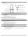
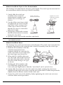
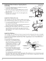
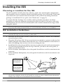
Integrated Sensor Suite
Installation Manual
Rev. C, 11/19/09
At Davis, we believe in constant change! We’re always finding ways to
improve our products and our documentation.
Here is a summary of important changes from Rev. A. (Version and date
are on the inside cover of printed manuals.)
Page 3
Attach the Wind Vane
When attaching the wind vane to the shaft, make sure the end of the
shaft protrudes slightly beyond the bottom surface of the wind vane.
Page 6
Verify Data from the ISS
Please note that for best reception during initial reception, the console
and ISS should be at least 10 feet (3 meters) apart. Also note that while
inital reception of a packet usually happens within 2 or 3 minutes, it may
take up to 10 minutes depending on specific environmental conditions.
Davis Instruments, 3465 Diablo Avenue, Hayward, CA 94545 USA • 510-732-9229 • www.davisnet.com
Integrated Sensor Suite
Installation Manual
Model #6357
3465 Diablo Ave., Hayward, CA 94545 USA
510.732.9229 • www.davisnet.com
Table of Contents
Introduction .....................................................................................................1
Included Components and Hardware .........................................................1
Vantage Vue ISS Components ...........................................................1
Hardware ..............................................................................................2
Tools Needed .......................................................................................2
Preparing the ISS for Installation ..................................................................2
Attach the Wind Cups to the Anemometer .....................................3
Attach the Wind Vane .........................................................................3
Install the Rain Collector Tipping Spoon Assembly .......................4
Install the Debris Screen .....................................................................4
Install the Battery .................................................................................4
Advanced Installations: Confirm the Transmitter ID .....................5
Advanced Installations: Set a New Transmitter ID.........................5
Verify Data from the ISS .....................................................................6
Installing the ISS ..............................................................................................7
Choosing a Location for the ISS ...........................................................7
ISS Installation Guidelines ....................................................................7
Mounting the ISS .....................................................................................8
Finishing the Installation .....................................................................10
Maintenance and Troubleshooting .............................................................11
Appendix A: Specifications .........................................................................13
FCC Part 15 Class B Registration Warning
This equipment has been tested and found to comply with the limits for a Class B digital device, pursuant to Part
15 of the FCC Rules. These limits are designed to provide reasonable protection against harmful interference in
a residential installation. This equipment generates, uses, and can radiate radio frequency energy and, if not
installed and used in accordance with the instructions, may cause harmful interference to radio communications.
However, there is no guarantee that interference will not occur in a particular installation. If this equipment does
cause harmful interference to radio or television reception, which can be determined by turning the equipment on
and off, the user is encouraged to try to correct the interference by one or more of the following measures:
•
Reorient or relocate the receiving antenna.
•
Increase the separation between the equipment and receiver.
•
Connect the equipment into an outlet on a circuit different from that to which the receiver is connected.
•
Consult the dealer or an experienced radio/TV technician for help.
Changes or modification not expressly approved in writing by Davis Instruments may void the warranty and void
the user's authority to operate this equipment.
FCC ID: IR2DWW6357
IC: 3788A-6357
EC EMC Compliance: This product complies with the essential protection requirements of the EC EMC Directive
2004/108/EC; Low Voltage Directive 2006/95/EC; and Eco-Design Directive 2005/32/EC >.5 watt no-load adaptor. RoHS Compliant
Integrated Sensor Suite Installation Manual.
Rev. C, November 19, 2009
Document Part Number: 07395.262
For Vantage Vue Weather Stations and Systems
™
3465 Diablo Avenue, Hayward, CA 94545-2778 U.S.A.
510-732-9229 • Fax: 510-732-9188
E-mail: [email protected] • www.davisnet.com
Vantage Vue is a trademark of Davis Instruments
Corp., Hayward, CA.
© Davis Instruments Corp. 2009. All rights reserved.
Information in this document subject to change without notice
Introduction
The Vantage VueTM wireless Integrated Sensor Suite (ISS) collects outside weather
data and sends the data wirelessly to a Vantage Vue console via a low-power radio.
The ISS is solar powered and includes a battery back-up.
The Vantage Vue ISS contains a rain collector, temperature/humidity sensor,
anemometer, and wind vane. The temperature/humidity sensor is mounted in a
passive radiation shield to minimize the impact of solar radiation on sensor readings.
The anemometer measures wind speed, and the wind vane measures wind direction.
The Sensor Interface Module (SIM) is housed within the ISS and comprises the
“brains” of the Vantage Vue system and the radio transmitter. The SIM collects
outside weather data from the ISS sensors and transmits that data to your Vantage
Vue console.
Note:
Your Vantage Vue ISS can transmit to an unlimited number of consoles, so you can purchase additional
consoles to use in different rooms. It can also transmit to Davis Vantage Pro2 consoles and Davis
Weather Envoys as well as Vantage Vue consoles.
Included Components and Hardware
Vantage Vue ISS Components
Rain collector
debris screen
Wind cups
Solar panel
Radiation
shield
Wind vane
Tipping spoon
(rain) assembly
1
Hardware
Hardware included with the Vantage Vue ISS:
Battery cover with
thumbscrew
U-Bolt
3-Volt lithium battery
Backing plate
1/4” lock washers
1/4” hex nuts
Note:
Debris screen
0.05” Allen wrench
If any of the hardware components are missing or not included, contact Customer Service toll free at
1-800-678-3669 about receiving replacement hardware or other components.
Tools Needed
• Adjustable wrench or 7/16” (11 mm) wrench
• Compass or local area map
Preparing the ISS for Installation
Follow the steps in the order; each builds on tasks completed in previous steps.
Note:
Use a clean, well-lit work table or work area to prepare the ISS for installation.
1.
2.
3.
4.
5.
Note:
Attach the wind cups to the anemometer
Attach the wind vane
Install the rain collector tipping spoon assembly
Install the debris screen in the rain collector
Install the ISS battery to apply power
At this point, we recommend that you set up your console, and then come back to finish the installation of
the ISS. See your Vantage Vue Console Manual.
Additional steps for advanced set up:
• Verify transmitter ID
• Change the transmitter ID for wireless communication, if necessary
6. Verify data from the ISS
2
Attach the Wind Cups to the Anemometer
The Vantage Vue anemometer measures wind speed. The wind cups are mounted on
the anemometer shaft on the top of the ISS assembly.
1. Gently slide the wind cup
Install cups onto
assembly down onto the
stainless steel shaft.
anemometer’s stainless steel
shaft as far as it will go, as
shown.
2. Use the Allen wrench provided
to tighten the set screw near the
top of the “hub” section of the
wind cups, as shown. Ensure
that the set screw is screwed in
fully and is tight.
3. Pull gently on the hub to ensure
that the anemometer is securely
fastened to the shaft.
4. Spin the wind cups to make sure they spin freely.
Note:
Tighten set screw
with Allen wrench.
If the wind cups don’t spin freely, loosen the set screw, remove them from the shaft, and repeat the wind
cup installation process.
Attach the Wind Vane
The Vantage Vue wind vane measures wind direction. The wind vane is mounted on
a stainless steel shaft on the opposite side of the ISS assembly from the wind cups.
1. Hold the ISS assembly on its side
with the anemometer and
radiation shields on your left, the
wind vane shaft on your right and
the wind cups away from you.
2. When the ISS is held in this manner, the wind vane shaft is horizontal, and will orient itself so that its
flat side will be facing to the right,
as shown.
3. Holding the ISS assembly with
your left hand, grasp the wind
vane with your right hand so that the “arrowhead” end is pointed down.
4. Gently slide the wind vane onto the wind vane shaft, rotating the wind vane
slightly left and right if necessary, until the end of the shaft is visible and protrudes
slightly from the bottom surface of the wind vane.
5. Secure the wind vane to the shaft by firmly tightening the wind vane set screw
with the Allen wrench provided.
3
Install the Rain Collector Tipping Spoon
Assembly
Tipping spoon
assembly slot
1. Locate the tipping spoon assembly slot on the
underside of the ISS Base.
2. Insert the wider end of the tipping spoon assembly into the slot first, sliding it under the raised
lip of the slot.
3. Fit the narrow end into the slot and tighten the
thumbscrew securely.
Tipping spoon
assembly
Install the Debris Screen
The Vantage Vue ISS rain collector debris screen captures debris that may otherwise clog your rain collector.
1. Locate the small black plastic ISS debris screen in
your hardware package.
The debris screen has four small tabs that hold it in
place in the base of the rain collector.
2. Holding the ISS assembly with one hand, and holding the debris screen by the top, press it into the
opening in the rain collector until the tabs snap into
the opening.
Install the Battery
The Vantage Vue ISS SIM board stores energy from the solar panel for power at night.
A 3-volt lithium battery provides a backup power source. The battery compartment is
located on the underside of the ISS base. The compartment cover is included in the
hardware packet.
To install the ISS backup battery.
1. Insert the 3-volt lithium battery
into the ISS battery compartment,
being sure to match the “+” sign
on the battery with the “+” sign
embossed on the inside of the
battery compartment.
2. Ensure that the battery is properly in place, install the battery
compartment cover, and tighten
the thumbscrew.
Transmitter ID
pushbutton
Battery
compartment
Transmitter ID
LED
Battery compartment
cover
To verify power, wait 30 seconds
then push and release the white transmitter ID pushbutton next to the battery compartment. The green transmitter ID LED next to the battery compartment will illuminate when you press the pushbutton.
4
Note:
Press the pushbutton once and release it. Do not press it multiple times or hold it down.
When you release the pushbutton, the LED will blink once (indicating transmitter
ID 1), then begin to flash every 2.5 seconds to show transmission of a data packet.
This flashing will stop within a few minutes to conserve battery life.
Note:
If you have not already set up and powered your Vantage Vue console, do so before continuing with the
ISS installation. For best reception, the console and ISS should be at least 10 feet (3 meters) apart.
3. The console acquires the radio signal and populates data fields. This usually
occurs quickly, but in some enviromental conditions it can take up to 10 minutes.
Advanced Installations: Confirm the Transmitter ID of the ISS
Your Vantage Vue console can be used to listen to a Vantage Pro2 ISS instead of a Vantage Vue ISS, and an optional anemometer transmitter kit.
Note:
If you are using only the Vantage Vue console and ISS, and there are no other Davis weather stations
nearby, you can skip to “Verify Data from the ISS” on page 6.
In order to communicate, the console
and ISS must have the same transmitter
ID. At the factory, both IDs are set to a
default of number 1. To confirm the
transmitter ID of your Vantage Vue ISS:
1. Push and release the transmitter ID
pushbutton once. It will illuminate
and go off when you release it.
2. After a short pause, it will blink one or
more (up to 8) times. Note the number
of times the transmitter ID LED
blinks, indicating its transmitter ID.
Transmitter ID
pushbutton
Transmitter ID
LED
Unless you have intentionally changed your transmitter ID, the LED should blink
one time because the default transmitter ID for the ISS is “1.” If you have changed
the ID, the LED should blink the number of times equal to the ID you have set (i.e.,
twice for an ID of ‘2,’ three times for an ID of ‘3,’ etc.).
After blinking the transmitter ID, the light will begin to flash every 2.5 seconds,
indicating packet transmission.
Note:
The transmitter on the ISS and receiver on the console will communicate with each other only when both
are set to the same transmitter ID.
Note:
If you hold the pushbutton too long and accidentally enter the “set new transmitter ID” mode when you did
not want to, simply release the pushbutton and wait four seconds. As long as you do not press the pushbutton again, the original transmitter ID will remain in effect.
Advanced Installations: Set a New Transmitter ID on the ISS
Note:
In most cases, it will not be necessary to change the transmitter ID. If it is necessary to change the transmitter ID, you must use the same ID for the ISS and console.
The Vantage Vue ISS transmits weather information to the Vantage Vue console using
one of eight selectable transmitter IDs. The default transmitter ID for both the ISS and
the Vantage Vue console is 1. Change the transmitter ID if another Davis Instruments
5
wireless weather station is operating nearby and already uses transmitter ID 1, or if
you have an optional Anemometer Transmitter Kit with ID 1.
To set a new transmitter ID:
1. Push and hold the transmitter ID pushbutton until the LED begins flashing
quickly. This indicates it is in the setup mode.
2. Release the pushbutton, and the LED will go dark.
3. Push the pushbutton the number of times equal to your desired new transmitter
ID. That is, if you want to change the ID to “3,” push the pushbutton three times;
for a desired ID of “4,” push the pushbutton four times.
After four seconds have elapsed with no further presses, the LED will blink the
same number of times as the new transmitter ID. (After blinking the transmitter ID
number, the light will begin to flash each time a packet is transmitted, about every
2.5 seconds.)
Verify Data from the ISS
To verify reception of ISS data by the Vantage Vue console, you will need your
powered-up console and the ISS. For best reception, the console and ISS should be at
least 10 feet (3 meters) apart.
1. If the console is in Setup Mode, press and hold DONE until the Current Weather
screen displays. The antenna icon appears under the wind compass rose. Watch
this icon to see that “transmission waves” appear, indicating reception of a packet.
Sensor readings from the ISS should display on the screen within a few minutes.
2. At the top right corner of the screen, look for the outside temperature.
3. Gently spin the wind cups to check wind speed, pressing the WIND button on the
console to alternate between speed and direction in the windcompass rose.
4. Gently turn the wind vane, and allow 5 seconds for the wind direction display to
stabilize before moving it again.
Note:
A good way to ensure that your console is listening to your ISS and not another Davis station nearby, is to
make sure the wind values displayed match your wind vane’s direction in reference to the solar panels,
which are assumed to be facing south. For example, if you move the vane to point directly away from the
ISS, the console should show a wind direction of south; if you then turn the vane 180° so it is pointed
back at the radiation shield, the wind direction on the console should change to north.
5. Approximately one minute after acquisition of the signal, the outside relative
humidity reading should be displayed on the console, below the outside temperature display.
6. Confirm rain display. On your console screen, select the RAIN DAY display. (See
Vantage Vue Console Manual.). Carefully hold your ISS over a sink and, while watching the RAIN DAY display on your console, slowly pour one-half cup of water into
the Rain Collector. Wait two seconds to see if the display registers a rain reading.
Note:
This method confirms that the rain display is functioning. It cannot be used to verify accuracy.
7. Current data displayed on the console confirms successful communication.
Note:
In some cases it may take as long as ten minutes for a reading to register on your console.
If communication problems exist between the wireless ISS and the console, see
“Troubleshooting ISS Reception” on page 12.
6
Choosing a Location for the ISS
Installing the ISS
Choosing a Location for the ISS
The ISS assembly includes the rain collector, wind vane, anemometer, temperature
and humidity sensors, radiation shield, and SIM housing. You will use the U-bolt and
associated nuts and washers that are included with your ISS mounting hardware
package to install the ISS on a pole. (See “Hardware” on page 2.)
To ensure that the Vantage Vue weather station performs at its best, use these
guidelines to select the optimum mounting location for the ISS. Be sure to take into
consideration ease of access for maintenance and wireless transmission range when
siting the station.
Note:
When selecting a location for installing your ISS, especially on a rooftop, make sure it is a location far
from power lines. Seek professional help if you are uncertain about the safety of your installation.
ISS Installation Guidelines
Note:
These siting guidelines reflect an ideal condition. Rarely is it possible to create the perfect installation.
The better the siting, the more accurate your data will be.
• Place the ISS away from sources of heat such as chimneys, heaters, air conditioners and exhaust vents.
• Place the ISS at least 100' (30 m) away from any asphalt or concrete roadway that
readily absorbs and radiates heat from the sun. Avoid installations near fences or
sides of buildings that receive a lot of sun during the day.
• Install the ISS as level as possible to ensure accurate rain and wind measurements.
Use the built in bubble level on the top of the ISS, just above the solar panel, to
make sure the ISS is level.
• In the Northern Hemisphere, the solar panel should face south for maximum sun
exposure.
• In the Southern Hemisphere, the solar panel should face north for maximum sun
exposure.
SOUTH
(in the Northern
Hemisphere)
NORTH
(in the Southern
Hemisphere)
Note:
Solar Panel
If you install the ISS with the solar panel pointing in a direction other than south, you will need to use the
wind direction calibration function in the Vantage Vue console in order to obtain accurate wind direction
readings. See Vantage Vue Console Manual for more information.
7
ISS Installation Guidelines
• Ideally, mount the ISS so that it is between 5’ (1.5 m) and 7’ (2.1 m) above the
ground in the middle of a gently sloping or flat, regularly mowed grassy or naturally landscaped area that drains well when it rains. You can also mount the ISS
on the roof, between 5’ (1.5 m) and 7’ (2.1 m) above the roof surface. For areas
with average maximum yearly snow depths over 3’ (0.9 m), mount the ISS at least
2’ (0.6 m) above this depth.
• Never install the ISS where it will be directly sprayed by a sprinkler system.
• Avoid installations near bodies of water such as swimming pools or ponds.
• Do not locate the ISS under tree canopies or near the sides of buildings that create
“rain shadows.” For heavily forested areas, site the ISS in a clearing or meadow.
• Site the ISS in a location with good sun exposure throughout the day.
• For agricultural applications:
•
Install the ISS so that it is between 5’ (1.5 m) and 7’ (2.1 m) above the ground
and in the middle of the farm between similar crop types (ie. two orchards,
two vineyards, or two row crops), if possible.
•
Avoid areas exposed to extensive or frequent applications of agricultural
chemicals (which can degrade the sensors).
•
Avoid installation over bare soils. The ISS performs best when installed over
well-irrigated, regularly mowed grass
•
If the last three guidelines cannot be met, install the ISS at the edge of the primary crop of interest.
Siting guidelines that may affect the anemometer
• For optimal wind data, mount the ISS so that the wind cups are at least 7’ (2.1 m)
above obstructions such as trees or buildings that may obstruct wind flow.
• For optimal wind data, you may mount the ISS on a roof, keeping in mind ease of
access to the ISS for maintenance and safety considerations. Ideally, mount it so
that the wind cups are at least 7’ (2.1 m) above the roof apex.
• The standard for meteorological and aviation applications is to place the anemometer 33’ (10 m) above the ground. Seek professional help for this such installation.
• The standard for agricultural applications is to place the wind cups 6’ (2 m) above
the ground. This is important for evapotranspiration (ET) calculations.
Note:
For roof mounting, and ease of installation, we recommend using the optional tripod (#7716). For other
installations, use the Mounting Pole Kit (#7717).
Note:
For more detailed siting suggestions, see Application Note #30 on the Davis Support website (http://
www.davisnet.com/support/weather).
Mounting the ISS
The Vantage Vue ISS can only be mounted on the top of a pole or rod.
Note:
8
A mounting pole is not included with your Vantage Vue ISS and must be purchased separately, either
from Davis Instruments or from your local hardware retailer.
ISS Installation Guidelines
Recommended Accessories for Pole Mounting
• Use the Mounting Tripod (#7716) for easiest mounting.
• Use the Mounting Pole Kit (#7717) to raise the installation height of the ISS by
up to 37.5" (0.95 m).
General Guidelines for Installing on a Pole
• With the supplied U-bolt, the ISS can be mounted on a pole or rod having an
outside diameter ranging from 1" to 1.75" (25 – 44 mm).
• To mount on a smaller pole, obtain a U-bolt that fits the base openings but that
has a longer threaded section. If mounting the ISS on a smaller pole with the
included U-bolt, the threaded sections of the U-bolt will be too short to securely
mount the ISS.
C-shaped
bracket
Installing the ISS on a Pole
1. If you are mounting your ISS on a Davis Mounting Tripod or the pole included
with a Davis Mounting Pole Kit, follow the instructions included with those Davis
products for proper installation.
If you are not using one of these Davis products, mount on a galvanized steel pole
having an outside diameter ranging from 1" to 1.75" (25 – 44 mm).
Note:
It is important that the mounting pole be plumb. You may wish to use a level such as a magnetic ”torpedo
level” to assure that the ISS, when mounted on top of the pole, will be level.
2. Using the illustration above as a guide, hold the ISS so that the wind cups and radiation shield are on the left and gently place the ISS on top of the pole.
3. While holding the mounting base of the ISS against the pole, place the two ends of
the U-bolt around the pole and through the two holes in the C-shaped bracket on
the base.
4. Slide the metal backing plate over the bolt ends where they extend out from the far
side of the bracket.
5. Secure the backing plate with a lock washer and hex nut on each of the bolt ends,
as shown in the illustration.
9
ISS Installation Guidelines
6. Tighten the hex nuts with your fingers only so that the ISS is just secure enough
on the pole for you to release your grip.
7. If you are in the Northern Hemisphere, rotate the ISS on the pole so that the solar
panel is facing south; if you are in the Southern Hemisphere, rotate the ISS so that
the solar panel is facing north. The more precisely the solar panels face due south
or north, the more accurate your wind direction readings will be.
Note:
Do not rely on a compass unless it is properly calibrated. In North America there can be up to 15° variation between true north and a raw compass reading.
8. When the ISS is properly oriented, tighten the hex nuts with a wrench. Do not
exceed 96 inch-pounds (10.8 newton-meters) of torque.
Note:
You can refer to the bubble level on the top of the ISS to make sure it is as level as possible.
Finishing the Installation
The wind vane is calibrated at the factory to be accurate when the solar panel is pointing south. If your solar panel does not point south, you must calibrate your console so
that it displays accurate wind direction readings. In any case, you can also calibrate
your console to fine-tune your station for greatest accuracy. Refer to your Vantage Vue
Console Manual to calibrate your console.
Note:
Calibration must be done if you are in the Southern Hemisphere, or if you are in the Northern Hemisphere
and cannot install your ISS with the solar panel facing south.
Clearing Data Collected During Testing and Installation
Now that the ISS is mounted outside, any data that was collected and stored in the
console during testing and mounting should be cleared.
To clear all the collected data on the console:
1. On the console, press WIND so that selection arrow appears adjacent to the wind
data on the display. Confirm that wind speed is displayed on the compass rose.
2. Press 2ND, then press and hold CLEAR for at least six seconds and until you see
“CLEARING NOW” in the weather center.
10
Maintenance and Troubleshooting
Maintenance
Cleaning the Radiation Shield
The outer surface of the radiation shield should be cleaned when there is excessive
dirt and build-up on the plates. Use a damp cloth to clean the outer edge of each ring.
Note:
Spraying down or using water excessively to clean the radiation shield can damage the sensitive sensors
or alter the data the ISS is transmitting.
Check the radiation shield for debris or insect
nests at least once a year and clean when
necessary. A buildup of material inside the shield
reduces its effectiveness and may cause
inaccurate temperature and humidity readings.
1. Using a Phillips head screwdriver, loosen the
two #6 x 2 1/2” screws holding the five radiation shield plates together, as shown.
2. Taking care to maintain the order in which the
five plates are assembled, separate the plates
as shown and remove all debris from inside
the shield.
3. Reassemble the plates in the same order in
which they were disassembled, and fasten
them together using a Phillips head screwdriver to tighten the #6 x 2 1/2” screws, as
shown.
Solid plates,
drain holes
toward
mounting pole
Cleaning the Rain Collector, Debris
Screen, and Tipping Spoon Module
To maintain accuracy, thoroughly clean the rain collector cone and debris screen as
needed or at least once a year.
Note:
Cleaning the rain collector and tipping spoon may cause false rain readings. See “Clearing Data Collected During Testing and Installation” on page 10.
1. Use a damp, soft cloth to remove any debris from the rain collector and debris
screen.
2. Use pipe cleaners to clear any debris remaining in the screen.
3. When all parts are clean, rinse with clear water.
11
Troubleshooting
To clean the tipping spoon assembly, it must first be removed from the ISS base.
1. Unscrew the thumbscrew securing the tipping
spoon assembly to the ISS base. Slide the assembly
down and away from the base.
2. Use a damp, soft cloth to gently remove any debris
from the tipping spoon assembly, being careful not
to damage any moving parts or scratch the spoon.
3. When all parts are clean, rinse with clear water,
and replace the assembly. (See “Install the Rain
Collector Tipping Spoon Assembly” on page 4.)
Troubleshooting
Troubleshooting ISS Reception
If the console isn’t displaying data from the ISS:
1. Verify that the ISS and console are powered and that the console is not in Setup
Mode. (See Vantage Vue Console Manual.)
2. Make sure that the ISS battery is properly installed.
3. Walk around the room with the console, standing for a few moments in various
locations, to see if you are picking up signals from the ISS. Look on the screen
below the wind compass rose for the small graphic of a radio antenna.
Note:
If you do not see the antenna icon, press 2ND and SETUP to enter Setup Mode, then press DONE to
return to the Current Weather Screen. The icon should appear.
4. Small “transmission waves” display above the antenna icon and toggle on and off
when the console receives a transmission.
If you do not see the antenna’s transmission wave graphic slowly blinking, regardless of where you stand with the console, you should call Technical Support.
5. If the Transmitter ID LED does not light after pressing the Transmitter Pushbutton,
there is a problem with the ISS transmitter. Call Technical Support.
6. If, after pressing the Transmitter Pushbutton, the Transmitter ID LED flashes every
2.5 seconds (indicating transmission) but your console isn’t picking up a signal
anywhere in the room, it could be related to one of the following causes:
• You changed the ISS Transmitter ID at the ISS or console, but not at both.
• Reception is being disrupted by frequency interference from outside sources, or
the distance and barriers are too great.
Note:
Interference has to be strong to prevent the console from receiving a signal while in the same room as the
ISS.
• There is a problem with the Vantage Vue console.
7. If a problem with receiving the wireless transmission still exists, please contact
Technical Support.
Note:
12
See “Contacting Davis Instruments” on page 13.
Troubleshooting
Problems Using Two Transmitting Stations
A single Vantage Vue console can receive signals from one ISS, either a Vantage Vue
or a Vantage Pro2 ISS, and an optional anemometer transmitter kit. Make sure the
transmitter IDs are configured correctly. See your Vantage Vue Console Manual for
information on configuring transmitter IDs.
Most Common Rain Collector Problem
“My rain data seems too low.”
If the rain collector seems to be under-reporting rainfall, clean the debris screen
and tipping spoon module to clear out any debris.
Most Common Anemometer Problems
“The wind cups are spinning but my console displays 0 mph.”
The wind cups may not be turning the shaft. Remove the cups from the
anemometer by loosening the set screw. Put the cups back onto the shaft and
make sure to slide them down the shaft as far as possible. Retighten the set
screw.
“The wind cups don’t spin or don’t spin as fast as they should.”
The anemometer may be located where wind is blocked by something, or there
may be friction interfering with the cups’ rotation. Remove the wind cups by
loosening the set screw, and clear out any insects or debris which may be
interfering with the cup rotation. Turn the shaft the cups rotate on. If it feels
gritty or stiff, contact Davis Technical Support.
Note:
Do not lubricate the shaft or bearings in any way.
“Readings aren’t what I expected them to be.”
Comparing data from your ISS to measurements from TV, radio, newspapers, or
a neighbor is NOT a valid method of verifying your readings. Readings can vary
considerably over short distances. How you site the ISS and anemometer can
also make a big difference. If you have questions, contact Davis Technical
Support.
Contacting Davis Instruments
If you have questions about the ISS or Vantage Vue system, or encounter problems
installing or operating the weather station, please contact Davis Technical Support.
Note:
Please do not return items to the factory for repair without prior authorization.
(510) 732-7814 – Technical Support phone, Monday – Friday, 7:00 a.m. – 5:30 p.m.
Pacific Time.
(510) 670-0589 – Technical Support Fax.
[email protected] – E-mail to Technical Support.
[email protected] – General e-mail.
www.davisnet.com – Download manuals and specifications from the Support section.
Watch for FAQs and other updates. Subscribe to the e-newsletter.
13
Appendix A: Specifications
See complete specifications for your Vantage Vue station on our website:
www.davisnet.com
Integrated Sensor Suite (ISS) Specifications
Operating Temperature................................... -40° to +150°F (-40° to +65°C)
Non-operating (Storage) Temperature ............-40° to +158°F (-40° to +70°C)
Current Draw (ISS SIM only)........................... 0.20 mA (average), 30 mA (peak) at 3.3
VDC
Solar Power Panel (ISS SIM) .......................... 0.5 Watts
Battery (ISS SIM)............................................ CR-123 3-Volt Lithium cell
Battery Life (3-Volt Lithium cell) ...................... 8 months without sunlight - greater than
2 years depending on solar charging
Connectors, Sensor ........................................ Pogo Pins
Cable Type ..................................................... 6-conductor, 28 AWG
Wind Speed Sensor ....................................... Wind cups with magnetic switch
Wind Direction Sensor ................................... Wind vane with magnetic encoder
Rain Collector Type ....................................... Tipping spoon, 0.01" per tip (0.2 mm
with metric rain cartridge, Part No.
7345.319), 17.7 in2 (114 cm2) collection
area
Temperature Sensor Type .............................. PN Junction Silicon Diode
Relative Humidity Sensor Type ....................... Film capacitor element
Housing Material............................................. UV-resistant ABS & ASA plastic
WIND
TEMPERATURE
RAIN
HUMIDITY
BAR
Update Interval by Sensor
14
Barometric Pressure
1 min.
Inside Humidity
1 min.
Outside Humidity
50 sec.
Dew Point
10 sec.
Rainfall Amount
20 sec.
Rain Storm Amount
20 sec.
Rain Rate
20 sec.
Inside Temperature
1 min.
Outside Temperature
10 sec.
Heat Index
10 sec.
Wind Chill
10 sec.
Wind Speed
2.5 sec.
Wind Direction
2.5 sec.
Direction of High Speed
2.5 sec.