1
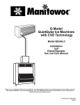
S Model QuietQube® Ice Machines
with CVD® Technology
Installation Training
Overview
³ Compressor, Condenser,
Accumulator and HPCV are Outside
³ Line Set is:
³ High Pressure Liquid Line
³ Low Pressure Suction Line
³ Evaporator, Receiver and Harvest Valve in
Head Section
No Interconnecting Control Wiring!
Typical QuietQube System
Installation
Model Numbers
This training covers the following models:
Ice Machine Head Section
CVD Condensing Unit
SD0672C
SY0674C
CVD0675
SD0872C
SY0874C
CVD0885
SD1072C
SY1074C
CVD1085
SD1272C
SY1274C
CVD1285
SD1472C
SY1474C
CVD1485
SD1872C
SY1874C
CVD1885
SD2072C
SY2074C
CVD2075
Important Information
Prior to Installation
³ Read Installation, Use & Care Manual
S Model QuietQube ice machines cannot
be stacked.
Failure to follow installation guidelines may
affect warranty coverage.
Manitowoc remote systems are only
approved and warranted as a complete
new package. Warranty on the
refrigeration system will be void if a new
ice machine head section is connected to
pre-existing (used) tubing or condensing
units or vice versa.
WARNING
PERSONNEL INJURY POTENTIAL
Do not operate equipment that has been misused,
abused, neglected, damaged, or altered/modified
from that of original manufactured specifications.
WARNING
Prior to installation make sure that all bin adapters
and ice deflectors
When using a non-Manitowoc ice storage system
with Manitowoc ice machines, contact the
manufacturer to assure their ice deflector is
compatible with Manitowoc ice machines.
Verify Components
Next verify that you have all the correct components
for the ice machine that is being installed
³Bin
³Adapters
³Kits
³Location
Installation Requirements
The location selected for the ice machine must meet the following criteria. If
any of these criteria are not met, select another location.
³Must have open site (gravity) drain available (see Water Supply and Drain
Requirements).
³Must have a grounded, polarized electrical power supply on a dedicated
electrical circuit (only appliance on circuit). If GFCI (ground fault circuit
interrupter) is required by your local electrical code, it must be breaker type,
not outlet type.
³Must have cold water supply line available at Ice Machine (see Water Supply
and Drain Requirements).
³Clearance and air temperatures must be met.
Head Section
³ The air temperature must be at least 35°F (1.6°C), but must not
exceed 110°F (43.4°C).
³ The location must be free of airborne and other contaminants.
³ The location must not be near heat-generating equipment or in
direct sunlight.
³ The location must not obstruct airflow through or around the ice
machine.
Clearances
Top 5” (12.7 cm) is recommended for efficient operation and removal of top
cover/servicing.
Sides 5” (12.7 cm) is recommended for efficient operation and servicing.
There is no minimum clearance required.
Back 3” (7.6 cm) required when routing electrical inlet, water inlet and
refrigeration tubing out of the top of the unit.
5” (12.7 cm) required when routing all connections out the back.
Location of Condensing Unit
³ The air temperature must be at least -20°F (-28.9°C) but must
not exceed 130°F (54.4°C).
³ CVD675/CVD1185/CVD2075 Only - The air temperature must
be at least -20°F (-28.9°C) but must not exceed 120°F (48.9°C).
³ CVD1486 Only- The air temperature must be at least 50°F
(10°C) but must not exceed 110°F (43°C).
³ The location must not allow exhaust fan heat and/or grease to
enter the condenser.
³ The location must not obstruct airflow through or around the
condensing unit.
Condensing Unit Clearances
CVD675/CVD885/CVD1085/CVD1185/CVD2075
Top/Sides
There is no minimum clearance required, although 6” (15.2 cm)
is recommended for efficient operation and servicing only.
Front/Back
48” (122 cm)
CVD1285/CVD1485/CVD1885
Top/Sides
There is no minimum clearance required, although 6” (15.2 cm)
is recommended for efficient operation and servicing only.
Front
24” (61 cm)
Back
48” (122 cm)
CVD1486 ONLY
Top - 5” (12.7 cm) is required for efficient operation and
servicing.
Front/Back/Sides - 12” (30.5 cm)
CVD Rise & Drop
Verify the Condensing Unit and
Ice Machine Head Section are
within the guidelines
Electrical Service
Requirements
³ All electrical work, including wire routing and grounding, must
conform to local, state and national electrical codes. The following
precautions must be observed: The ice machine must be grounded.
³ A separate fuse/circuit breaker must be provided for each
condensing unit.
³ A qualified electrician must determine proper wire size dependent
upon location, materials used and length of run (minimum circuit
ampacity can be used to help select the wire size).
³ The maximum allowable voltage variation is +/-10 of the rated
voltage at ice machine start-up (when the electrical load is highest).
³ Check all green ground screws in the control box and verify they are
tight before starting the ice machine.
Head Section Electrical
Total
Amps
**Minimum Wire
Size Required by
Manitowoc
Minimum
Breaker Size
Required by
Manitowoc
Ice Machine
Voltage Phase Cycle
Maximum
Fuse/Circuit
Breaker
S0600C
115/1/60
230/1/50
15 amp
15 amp
1.1
0.6
#14 Solid Copper
Conductor
15 amp
15 amp
S0850C
115/1/60
230/1/50
15 amp
15 amp
1.1
1.5
#14 Solid Copper
Conductor
15 amp
15 amp
IB0620C
IB0820C
IB1020C
115/1/60
230/1/50
15 amp
15 amp
1.4
0.8
#14 Solid Copper
Conductor
15 amp
15 amp
S1000C
115/1/60
230/1/50
15 amp
15 amp
2.5
1.5
#14 Solid Copper
Conductor
15 amp
15 amp
S1200C
115/1/60
230/1/50
15 amp
15 amp
2.5
1.5
#14 Solid Copper
Conductor
15 amp
15 amp
S1470C
S1870C
S2070C
115/1/60
208-230/1/60
230/1/50*
15 amp
15 amp
15 amp
1.1
0.6
0.6
#14 Solid Copper
Conductor
15 amp
15 amp
15 amp
* Not available on S2070C models.
** All conductors must be solid copper wire
Due to continuous improvements, this information is for reference only. Please refer
to the ice machine and/or condensing unit serial number tags to verify electrical
data. Serial tag information overrides information listed here.
CVD Electrical
Condensing
Unit
Voltage/Phase/Cycle
Maximum Fuse/
Circuit
Breaker
Minimum
Circuit
Amps
**Minimum Wire Size Required by
Manitowoc
Minimum Breaker
Size Required by
Manitowoc
CVD0675
208-230/1/60
208-230/3/60
230/1/50
15 amp
15 amp
15 amp
9.6
7.3
9.0
#14 Solid Copper Conductor
#14 Solid Copper Conductor
#14 Solid Copper Conductor
15 amp
15 amp
15 amp
CVD0885
208-230/1/60
208-230/3/60
230/1/50
20 amp
15 amp
20 amp
11.8
9.1
10.0
#12 Solid Copper Conductor
#14 Solid Copper Conductor
#12 Solid Copper Conductor
20 amp
15 amp
20 amp
CVD1085
208-230/1/60
208-230/3/60
230/1/50
20 amp
15 amp
20 amp
12.5
9.4
10.9
#12 Solid Copper Conductor
#14 Solid Copper Conductor
#12 Solid Copper Conductor
20 amp
15 amp
20 amp
CVD1185
208-230/1/60
208-230/3/60
230/1/50
25 amp
15 amp
20 amp
15.7
10.8
11.2
#12 Solid Copper Conductor
#14 Solid Copper Conductor
#12 Solid Copper Conductor
25 amp
15 amp
20 amp
CVD1285
208-230/1/60
208-230/3/60
230/1/50
25 amp
20 amp
20 amp
14.7
10.6
11.7
#10 Solid Copper Conductor
#12 Solid Copper Conductor
#12 Solid Copper Conductor
25 amp
20 amp
20 amp
CVD1485
208-230/1/60
208-230/3/60
230/1/50
20 amp
15 amp
30 amp
20.0
15.0
20.0
#8 Solid Copper Conductor
#10 Solid Copper Conductor
#8 Solid Copper Conductor
20 amp
15 amp
30 amp
CVD1486
208-230/1/60
208-230/3/60
230/1/50
20 amp
15 amp
20 amp
20.0
15.0
20.0
#10 Solid Copper Conductor
#12 Solid Copper Conductor
#12 Solid Copper Conductor
20 amp
15 amp
20 amp
CVD1885
208-230/1/60
208-230/3/60
230/1/50
40 amp
25 amp
30 amp
25.0
20.0
20.0
#8 Solid Copper Conductor
#10 Solid Copper Conductor
#8 Solid Copper Conductor
40 amp
25 amp
30 amp
CVD2075
208-230/1/60
208-230/3/60
50 amp
40 amp
40.0
30.0
#10 Solid Copper Conductor
#10 Solid Copper Conductor
50 amp
40 amp
Verify Head Section
Always verify that you have received the correct
ice machine & condensing unit prior to installing
Model Number on Box
Inspection
³Remove carton & inspect ice machine and
condensing unit for shipping damage
Remove all Panels
Single Evaporator - Hinged Front Door Removal
³
³
³
³
³
³
Loosen Screws on the left and right front panels
Open the left front door 45 degrees and support with hand
Depress the top pin to disengage door, tilt forward
Lift off of bottom pin
The right front panel lifts up to disengage
Remove the top cover and the remaining panels
Remove all Panels
Dual Evaporator - Front Panel Removal
³ Loosen Screws on the front panel
³ The entire front panel lifts up to disengage
³ Remove the top cover and the remaining panels
Model/Serial Number Location
Back of
Ice Machine
Inside of
Ice Machine
Example Data Plate
Model Number
Serial Number – NO Date
code in new serial numbers
Refrigerant
Voltage
Manufactured
Date
Warranty Registration
Warranty Registration Form
Website
Level Bin
³Thread leveling leg into
base of bin
³Level the bin to assure
the bin door closes and
seals properly
Mount on Bin
³Place the ice machine
on top of the bin.
³Make sure ice machine
is flush with the sides of
the bin.
Ice Machine Wiring
³Install strain relief and proper wiring to ice
machine head section
Water Connections
Location
Water Temperature
Water Pressure
Ice Machine Fitting
Tubing Size Up to Ice
Machine Fitting
Ice Making Water
Inlet
35°F (1.6°C) Min.
90°F (32.2°C) Max.
20 psi (1.4 bar) Min.
80 psi (5.5 bar) Max.
3/8” Female Pipe
Thread
3/8” (9.5 mm) min.
inside diameter
Water Cooled
Condenser
35°F (1.6°C) Min.
90°F (32.2°C) Max
20 psi (1.4 bar) Min.
150 psi (10.3 bar) Max.
High Pressure Option
20 psi (1.4 bar) Min.
350 psi (24.1 bar) Max.
1/2” Female Pipe
Thread
1/2” (12.7 mm) min.
inside diameter
Ice Making Water
Drain
---
---
1/2” Female Pipe
Thread
1/2” (12.7 mm) min.
inside diameter
Bin Drain
---
---
3/4” Female Pipe
Thread
3/4” (19.1 mm) min.
inside diameter
Large Capacity
Bin Drain
---
---
1” Female Pipe
Thread
1” (25.4 mm) min.
inside diameter
Water Supply
³Do not connect the ice machine to a hot water
supply.
³If water pressure exceeds the maximum
recommended pressure (80 psi), obtain a
water pressure regulator from your Manitowoc
distributor.
Water Fittings
³ Do not apply heat (torch) to the Water Inlet Fitting or Drain
Fitting
³ Solder Water Connection before installing on ice machine
³ Water fittings have plastic and will melt when heated
³ Union must be installed to allow removal of ice machine
Potable Water Supply
³Installation with Water Filter
³ Install union, additional shut-off is not required
³ Copper or plastic tubing may be used
³ Refer to Arctic Pure Install Use and Care manual for
complete installation instructions
Potable Water Supply
³Water Installation without filter
³Install union and shut-off valve
Head Section Drains
³ Install 18” Vent Tubes
³Ice Machine & Bin drains must be run separately
³ Drains Must:
³Be run separately
³Have a minimum pitch of
1.5 inches every 5 feet
³ Floor Drain must be large
enough to accommodate
drainage from all drains
Roof Penetration
Verify Ice Machine and CVD® Condensing Unit Locations Are Within
Guidelines.
³ Prior to installation of the ice
machine head section and
CVD® condensing unit be
sure that the distance
between then is within the
line set routing guidelines.
Roof/Wall Penetration
³ If required, cut a 3-inch
(76.2 mm) circular hole in the
wall or roof for routing of
refrigeration tubing.
A qualified person must
perform all roof penetrations.
Lift Unit
³Trained & qualified
personnel are
required for rigging
and lifting
Curb & Pitch Pockets
³ The type of curbs
and pitch pockets are
dependant on the
roofing material.
³ Contact a roofing
company to install
the curb & pitch
pockets.
Place Units
³ Place condensing
units on curb and
secure
³ An electrician will
determine wire size
& install disconnect
for each condensing
unit
Refrigeration System Installation
³ The ice machine head section contains refrigerant
charge. The ice machine head section contains 3
refrigeration valves that must remain closed until
proper installation of the line sets is completed.
³ Disconnect electrical power to the ice machine
head section and CVD® condensing unit before
proceeding.
CVD Line Sets
QuietQube®
Ice Machine
Remote
Single Circuit
Condenser
S0600C
IB620C
CVD675
S0850C
IB820C
CVD885
S1000C
CVD1085
IB1020C
CVD1185
S1200C
CVD1285
S1470C
CVD1485
CVD1486
S1870C
CVD1885
S2070C
CVD2075
Line Set*
RC-21
RC-31
RC-51
RC-20
RC-30
RC-50
*Line Set
Suction
Line
Liquid Line
Insulation
Thickness
RC 21/31/51
5/8 inch
(15.9 mm)
3/8 inch
(9.5 mm)
1/2”(13mm)
Suction Line
1/4” (7mm)
Liquid Line
RC 20/30/50**
3/4 inch
(19.1 mm)
1/2 inch
(12.7 mm)
1/2”(13mm)
Suction Line
1/4” (7mm)
Liquid Line
**NOTE: The CVD2075 has a suction line fitting of 7/8” and a
liquid line fitting of 5/8”. Since the line set is sized differently,
please use the provided bushings to properly connect the line
set to the CVD Condensing Unit.
Line Set Length, Rise & Drop
LINE SET LENGTH
100 feet (30.5 m) Length:
The maximum measured length the
line set can be. The receiver is
designed to hold a charge sufficient
to operate the ice machine in
ambient temperatures between 20°F (-28.9°C) and 130°F
(54.4°C)*, with line set lengths of
up to 100 feet (30.5 m).
Suction Line Oil Traps
0 to 20 feet (0 to 6.1 m) Rise: The ice machine head section
has one oil trap built in which allows for a maximum condenser
rise of 20 feet (6.1 m) without additional traps in the suction line.
21 to 35 feet (6.4 to 10.7 m) Rise: The suction line requires an
additional Oil Trap (“S” type) to be installed. Install the trap as
close as possible to midpoint between the ice machine head
section and CVD condensing unit. See chart below for kits.
Model
S-Trap Kit
Number
Tubing Size
S600C
S850C
S1000C
K00172
5/8 inch (15.9 mm)
S1200C
S1470C
S1870C
S2070C
K00166
3/4 inch (19.1 mm)
Line Set Installation
³ Route refrigeration tubing
³ The maximum measured length
the line set can be is 100’ (30.5 m)
(no exceptions)
³ The maximum amount of line set
which can be exposed on the
rooftop is 25% of the total length of
the line set.
³ Do not expose more line set than
necessary to outdoor ambient
Suction Line Oil Traps
0 to 20 feet (0 to 6.1 m) Rise:
The ice machine head section has
one oil trap built in which allows
for a maximum condenser rise of
20 feet (6.1 m) without additional
traps in the suction line.
21 to 35 feet (6.4 to 10.7 m) Rise:
The suction line requires an
additional Oil Trap (“S” type) to be
installed. Install the trap as close
as possible to midpoint between
the ice machine head section and
CVD condensing unit.
Secure Line Set
³ Secure Line Set as
Needed
³ Do not crush/compress
insulation
Connect the Line Set
Ice Machine
The line set can be routed for entry through the top or rear of the
ice machine head section.
³ Top routing requires the cover to be trimmed.
³ Rear routing may require the use 90° elbows on some
models.
The line set shut off valves at the back of the ice machine must
remain closed and be protected from heat during the brazing
process. Wrap the valves in a wet rag or other type of heat sink
prior to brazing. Cool braze joint with water immediately after
brazing to prevent heat migration to the valve.
Connect the Line Set
Condensing Unit
³ The condensing unit ships from the factory pressurized with a 50/50
mixture of nitrogen/helium. Bleed off pressure from both suction and
liquid line access ports prior to cutting into refrigeration lines.
³ The compressor oil rapidly absorbs moisture. Be prepared to complete
line set installation and start your evacuation process in order to
minimize the time the compressor is exposed to the atmosphere.
(Maximum amount of time the system can be exposed to the
atmosphere is 15 minutes). The line set can be routed for entry through
the front or left side of the condensing unit.
³ Remove knockout for preferred location.
³ Insert supplied plastic bushings in knockout holes to prevent tubing
from contacting sheet metal.
³ Use the supplied 90° elbows to route tubing.
³ Cut the tubing ends of the suction and liquid lines and braze the
line sets to the condensing unit.
Pressure Test & Evacuate
Leave the line set shut off valves closed (front seated).
Pressure test the line sets and CVD condensing unit with
150 psig of dry nitrogen. Add nitrogen at the line set shut off
valves located at the back of the ice machine. Complete the
pressure test, verify no leaks are present and remove the
nitrogen from the system before connecting the vacuum
pump. Connect a vacuum pump to both of the line set shut
off valves located at the back of the ice machine head
section. Evacuate to 500 microns (or less). To completely
evacuate the CVD condensing unit, continue the
evacuation for 30 minutes after reaching the 500 micron
point.
Open the Valves Prior to Starting
Open The Valves Prior To Starting The Ice Machine.
A. Slowly backseat (open-turn counterclockwise)
the suction line shut off valve.
B. Slowly backseat (open-turn counterclockwise)
the liquid line shut off valve.
C. Slowly backseat (open-turn counterclockwise)
the receiver service valve.
NOTE: You will not hear refrigerant flow when the valves are opened.
Refrigerant will not flow until the toggle switch is placed in the ice
position and the solenoid valve opens.
Leak Check the System
³ Leak check the new line set connections at the ice machine
head section, condensing unit and S trap as well as all factory
joints throughout the entire system.
³ Disconnect power to the CVD condensing unit. Place the
ICE/OFF/CLEAN toggle switch into the ICE position. This allows
the low side and high side pressures to equalize.
³ Place the ICE/OFF/CLEAN toggle switch in the OFF position.
Connect power to the CVD condensing unit and allow system to
pump down.
Insulation Requirements
The following insulation requirements prevent condensation at
90°F (32.2°C) ambient 90% Relative Humidity. If higher
humidity is expected, increase insulation thickness.
Suction Line
Liquid Line
3/4 inch
(19.1 mm)
1/2 inch
(12.7 mm)
5/8 inch
(15.9 mm)
3/8 inch
(9.5 mm)
7/8 inch
(22.2 mm)
5/8 inch
(15.9 mm)
Min. Insulation
Thickness
1/2”(13mm) Suction Line
1/4” (7mm) Liquid Line
3/4” (19mm) Suction Line
1/4” (7mm) Liquid Line
Refrigerant Charge
The ice machine is
pre-charged with
refrigerant.
Additional refrigerant
may be required on
some models, when the
line set length is
between 50’ - 100’.
Final Set-Up
Installation Checklist
³Complete the installation checklist in the
Installation, Use & Care Manual
Complete Installation
³Sanitize the Ice Machine
³Energize
³Verify Water Level
³Run 2 Freeze Cycles
S Model QuietQube® Ice Machines
with CVD® Technology
Installation Quiz
Click Here to Launch