1
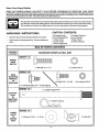
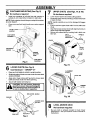
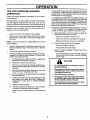
8E/ALR8
OWNER'S
MANUAL
MODEL NO.
917.249780
£RAFTSMAN°
Caution:
Read and follow
all Safety Rules
and Instruct,ons
Before Operating
This Equipment
38 INCH MOWER
GRASS CATCHER
• Assembly
• Operation
• Customer Responsibilities
• Repair Parts
Sears, Roebuck
and Co., Hoffman
Estates,
IL 60169 U.S.A.
A
SAFETY RULES
Safe Operation
Practices
for Ride-On
A
Mowers
_qL
IMPORTANT: THIS CU'I-FING MACHINE IS CAPABLE OF AMPUTATING HANDS AND FEETAND THROWING OBJECTS. FAILURE
TO OBSERVE THE FOLLOWING SAFETY INSTRUCTIONS COULD RESULT IN SERIOUS INJURY OR DEATH.
I°
GENERAL
OPERATION
DO NOT:
Read, understand, and follow all instructions in the manual
and on the machine before starting.
Only allow responsible adults, who are familiar with the
instructions, to operate the machine.
Clear the area of objects such as rocks, toys, wire, etc., which
could be picked up and thrown by the blade.
Be sure the area is clear of other people before mowing. Stop
machine if anyone enters the area.
Never carry passengers.
Do not mow in reverse unless absolutely necessary. Always
look down and behind before and while backing.
Be aware of the mower discharge direction and do not point
it at anyone. Do not operate the mower without either the
entire grass catcher or the guard in place.
Slow down before turning.
•
De not try to stabilize the machine by putting your foot on the
ground.
Do not use grass catcher on steep slopes.
IlL CHILDREN
Tragic accidents can occur if the operator is not alert to the
presence of children. Children are often attracted to the machine
and the mowing activity. Neverassume that children will remain
where you last saw them.
Never leave a running machine unattended. Always turn off
blades, set parking brake, stop engine, and remove keys
before dismounting.
Turn off blades when not mowing.
Stop engine before removing grass catcher or unclogging
chute.
Keep children out of the mowing area and under the watchful
care of another responsible adult.
Be alert and turn machine off if children enter the area.
Before and when backing, look behind and down for small
children.
Mow only in daylight or good artificial light.
Do not operate the machine while under the influence of
alcohol or drugs.
Watch for traffic when operating near or crossing roadways.
Never carry children. They may fall off and be seriously
injured or interfere with safe machine operation.
Never allow children to operate the machine.
Use extra care when approaching blind comers, shrubs,
trees, or other objects that may obscure vision.
Use extra care when loading or unloading the machine into
a trailer or truck.
IV. SERVICE
Data indicates that operators, age 60 years and above, are
involved in a large percentage of riding mower-related
injuries. These operators should evaluate their ability to
operate the riding mower safely enough to protect themselves and others from serious injury.
II.
Do not turn on slopes unless necessary, and then, turn
slowly and gradually downhill, if possible.
Do not mow near drop-offs, ditches, or embankments. The
mower could suddenly turn over if a wheel is over the edge
of a cliff or ditch, or if an edge caves in.
Do not mow on wet grass. Reduced traction could cause
sliding.
Use extra care in handling gasoline and other fuels. They
are flammable and vapors are explosive.
Use only an approved container.
Never remove gas cap or add fuel with the engine
running. Allow engine to cool before refueling. Do not
smoke.
Never refuel the machine indoors.
Never store the machine or fuel container inside where
there is an open flame, such as a water heater.
Never run a machine inside a closed area.
SLOPEOPERATION
Slopes are a major factor related to loss-of-control and tipover
accidents, which can result in severe injury or death. All slopes
require extra caution, if you cannot back up the slope or ifyou feel
uneasy on it, do not mow it.
DO:
Keep nuts and bolts, especialty blade attachment belts, tight
and keep equipment in good condition.
Never tamper with safety devices.
Check their proper
operation regularly.
Keep machine free of grass, leaves, or other debris build-up.
Clean oil or fuel spillage. Allow machine to cool before
storing.
Mow up and down slopes, not across.
Remove obstacles such as rocks, tree limbs, etc.
Watch for holes, ruts, or bumps.
Uneven terrain could
overturn the machine. Tall grass can hide obstacles.
Use slow speed. Choose a low gear so that you will not have
to stop or shift while on the slope.
Follow the manufacturer's
recommendations
for wheel
weights or counterweights to improve stability.
Use extra care with grass catchers or other attachments.
These can change the stability of the machine.
Keep all movement on the slopes slowand gradual Do not
make sudden changes in speed or direction.
Avoid starting or stopping on a slope. If tires lose traction,
disengage the blades and proceed slowly straight down the
slope.
Stop and inspect the equipment if you strike an object.
Repair, if necessary, before restarting.
Never make adjustments or repairs with the engine running.
Grass catcher components are subject to wear, damage,
and deterioration, which could expose moving parts or aUow
objects to be thrown. Frequently check components and
replace with manufacturer's
recommended parts, when
necessary.
Mower blades are sharp and can cut. Wrap the blade(s) or
wear gloves, and use extra caution when servicing them.
Check brake operation frequently. Adjust and service as
required.
2
SAFETY RULES
&
Safe Operation
Practices
for Ride-On
Be sure the area is clear of other people before mowing.
Stop machine if anyone enters the area.
Never carry passengers or children even with the blades
off.
&
Look for this symbol to point out important
safety precautions. It means CAUTION!!!
BECOME ALERT!!!
YOUR SAFETY IS INVOLVED,
Do not mow in reverse unless absolutely necessary. Always look down and behind before and while backing.
Never carry children. They may fall off and be seriously
injured or interfere with safe machine operation.
Keep children out of the mowing area and under the
watchful care of another responsible adult.
Be alert and turn machine off if children enter the area.
CAUTION:
Do not coast down a hill in
neutral, you may lose control of the tractor.
Before and when backing, look behind and down for small
children.
Mow up and down slopes (15 ° Max), not across.
Remove obstacles such as rocks, tree limbs, etc.
Watch for holes, ruts, or bumps. Uneven terrain could
overturn the machine. Tall grass can hide obstacles.
Use slow speed. Choose a low gear so that you will not have
to stop or shift while on the slope.
Avoid starting or stopping on a slope. If tires lose traction,
disengage the blades and proceed slowly straight down
the slope.
If machine stops while going uphill, disengage blades, shift
into reverse and back down slowly.
Do not turn on slopes unless necessary, and then, turn
slowly and gradually downhill, if possible.
Mowers
&
CAUTION: Tow only the attachments that
are recommended by and comply with
specificationsof the manufacturer of your
tractor. Use common sense when towing.
Operate only at the lowest possible speed
when on a slope. Too heavy of a load, while
on a slope, is dangerous. Tires can lose
traction with the ground and cause you to
lose control of your tractor.
CAUTION: In order to prevent accidental
starting when setting up, transporting, adjusting or making repairs, always disconnect spark plug wire and place wire where
it cannot contact spark plug.
CONGRATULATIONS
on your purchase of a new Grass Catcher. It has been designed, engineered
and manufactured to give you the best possible dependability and performance.
Should you experience any problems you cannot easily remedy, please contact your nearest authorized service center/department. They have competent, well trained technicians and the proper tools
to service or repair this unit.
Please read and retain this manual. The instructions will enable you to assemble
Grass Catcher properly. Always observe the "SAFETY RULES".
and maintain your
NOTE: To make debris disposal easier 30 gallon plastic trash bags may be inserted
containers. To order, see repair parts section of this manual.
in plastic grass
TABLE OF CONTENTS
SAFETY RULES .........................................................
BAG OF PARTS ............................................................
ASSEMBLY ................................................................
OPERATION ..................................................................
2_
4
5-8
9
CUSTOMER RESPONSIBILITIES ............................... 10
STORAGE ...................................................................
10
WARRANTY ................................................................
10
PREPARATION ...........................................................
11
REPAIR PARTS ......................................................
18-19
Know Your Grass Catcher
READ THIS OWNER'S MANUAL AND SAFETY RULES BEFORE ASSEMBLING OR OPERATING YOUR GRASS
CATCH ER. Compare the illustrations with the carton contents to familiarize yourself with the parts before starting the assembly.
Study the operating instructions and safety precautions thoroughly to insure proper functioning of your Grass Catcher and to
prevent injury to yourself and others. Save this manual for future reference.
UNPACKING
CARTON
INSTRUCTIONS
•
Remove all parts and packing materials from carton,
•
Check carton contents against list. Be sure all parts are
there.
CONTENTS:
(2) Container Tops
(2) Container Bottoms
(1) Upper Chute
(1) Lower Chute
(1) Mounting Bracket
(1) Support Post and
Cover Assembly
(1) Bag of Parts
(1) Owner's Manual
BAG OF PARTS CONTENTS
._,..._._
..ROW.RE
S.OW..CTU."
S.ZE
GROUP
"A"
I--
, ,,,
r
I
(4) Shoulder Bolts 5/16 - 18 Self Tapping'_
GROUP
"C" I
°
(1) Bracket Support Pin
_
suPPORT
l_ _
(1)Washer13/32xlx16Ga.'(/
/
_/
_c,,,
MC_U:EER
ITO
J
/
b
\
_F'_
_
°°C'l
_/
_\_
(1)WingNut/_,_,I
|
/
4
ASSEMBLY
BEFORE
YOU START TO ASSEMBLE
THE GRASS
CATCHER
Some tracto r models may need minor modifications before you can mount the grass catcher to the tractor. Look carefully at the mower
deck on your tractor and compare the deck mandrel to the illustrations below. If your mower deck mandrel looks like STYLE "A",
your tractor is ready - proceed with the grass catcher assembly. If your mower deck mandrel looks like STYLE "B", go to the
PREPARATION section in back of this manual.
DECK MANDREL
STYLE "A"
PARTS
IDENTIFICATION
DECK MANDREL
STYLE "B"
COVER
UPPER CHUTE
FULL
BAGGER
INDICATOR
CHUTE
LATCH
G
CATCHER
CONTAINERS
LOWER
CHUTE
LOWER CHUTE
ATTACHING
WING NUT
NOTE: When right hand (R.H.) and left hand (L.H.) are mentioned
in the operator's position.
CAUTION:
•
in this manual, it means when you are seated on the tractor,
BEFORE ASSEMBLING GRASS CATCHER TO TRACTOR:
Depress clutch/brake pedal fully and set parking brake.
Place attachment clutch in "DISENGAGED" position.
Place gearshift/motion control lever in neutral (N) position,
Turn ignition key "OFF" and remove key.
•
Make sure the blade and all moving parts have completely stopped.
•
Disconnect spark plug wire from spark plug and place wire where it cannot come in contact with
plug.
5
ASSEMBLY
If your tractor does not have four (4) shoulder bolts installed
on the drawbar, follow the instructions below.
MOWER DECK BAFFLE (See Fig. 1)
Use Hardware - - GROUP "A"
•
Raise your tractor mower deck to its highest position.
•
Install the hex bolt, and Iocknut through mower deck
baffle and tighten securely.
Use Hardware
- - GROUP
"B"
Only OReset of hardware in GROUP "B" will be used to mount
the rear mounting bracket. To determine which set is correct
for your tractor, check to see ifthere are (2) two upper comer
ribs on each side of drawbar. If your tractor has the upper
corner ribs, use the (4) four self tapping shoulder bolts. If your
tractor does not have the corner ribs, use the set of (4) four
bolts and Iocknuts.
HEX BOLT
SELF TAPPING SHOULDER BOLTS (See Fig. 2B)
•
Using the four formed holes in the drawbar, install the
four shoulder bolts as shown and tighten securely.
•
Hang the mounting bracket, lanced tabs towards bottom, on the bolts.
UPPER
RIBS
CORNER
LOCKNUT
MOWER
DECK BAFFLE
Fig, 1
REAR
MOUNTING
BRACKET
(See Figs. 2A, 2B & 2C)
LANCED TABS
TOWARD
BOTTOM
NOTE: If your tractor already has four (4) shoulder bolts
installed on the rear drawbar, simply hang the mounting
bracket, lanced tabs towards bottom, on the bolts. Discard
hardware group "B" and disregard the remaining Step 1
instructions•
Fig. 2B
BOLTS AND LOCKNUTS (See Fig. 2C)
IMPORTANT:
ON TRACTORS WITH FUEL TANK UNDER
THE SEAT, THE DRAWBAR MUST BE REMOVED FOR INSTALLATIONOF MOUNTING BRACKET.TO REMOVE DRAWBAR, REMOVE TWO HEX BOLTS ON BOTH SIDES OF DRAWBAR.
•
Assemble the mounting bracket, lanced tabs towards
bottom, using the four smaller inside holes on the
drawbar.
NOTE: Ifyour tractor drawbar does not have the fou rcorrect
holes for mounting the bracket, refer to the PREPARATION
section of this manual.
SHOULDER
BOLTS
•
Install the four bolts and Iocknuts as shown and tighten
securely.
•
If drawbar was removed from tractor, reassemble to
tractor at this time. Tighten securely.
BOLTS
LANCED TABS
TOWARD
BOTTOM
Fig. 2A
6
ASSEMBLY
MOUNTING
(See Fig. 3)
Use HardwareTO - TRACTOR
- GROUP "C"
CONTAINER
No hardware
ASSEMBLY
required
(See Fig. 4)
NOTE: For ease of assembly, you may wish to obtain the
assistance of another person for mounting assembly to
tractor.
•
Place bottom half inside of top half, as shown,
•
Place one foot inside bottom half and lifttop half to meet
bottom half,
•
Raise seat on tractor to allow assembly to be mounted.
•
•
With cover closed, lift assembly and place support post
inside mounting bracket. Allow assembly to rest on
lanced tabs of mounting bracket.
•
Line up holes in mounting bracket with holes in support
post and insert bracket support pin. Secure with retainer
spring.
•
Unlatch and open cover•
Press halves tightly together while lifting top to lock into
place as shown.
IMPORTANT: BEFORE LOCKINGTHETABS, HOOKED EDGES
ON BOTH HALVES MUST OVERLAP TO FORM SEAL AS
SHOWN IN INSET,
•
Repeat for second container.
CONTAINER
_/BOTTOM
HALF
COVER
ASSEMBLY
CONTAINER
TOP HALF
CONTAINER
BOTTOM
HALF
RETAINER
SPRING
:/
PRESS TOGETHER
TO FORM SEAL
WHILE LIFTING
TOP HALF
LOCKING
TAB
ASSEMBLY CHECK: Squeeze sides of lower half of container and check that there is no gap between upper and
lower halves. If a gap appears, unlock tabs to separate
container halves and repeat instructions above.
SUPPORT
LANCED
TABS
MOUNTING
BRACKET
Fig. 4
Fig. 3
7
ASSEMBLY
CONTAINER MOUNTING (See Fig. 5)
No hardware
•
UPPER CHUTE (See Figs. 7A & 7B)
No hardware required
required
Install one container to left side first with warning to
outside of unit. Install other container to right side.
•
•
NOTE: Right container should always overlap left container
at center support.
•
Lower mower deck to its lowest cutting position,
Assemble upper chute by inserting curved end intohole
in back of cover,
NOTE: Handle carefully so as not to damage full bagger
indicator.
Close cover and lock latch handle over center support
tube.
_
COVER LATCH
HANDLE
•
Push in and turn upper chute until it is in line with lower
chute.
•
Align the bosses on lower chute with alignment slots on
upper chute and slide together.
Secure with rubber latch by hooking hole in latch over
latch pin.
FULL
HANDLE
•
CONTAINER
BAGGER
INDICATOR
_
/
COVER
UPPER
CHUTE
CONTAINER
HANDLE
CENTER
SUPPORT
TUBE
LOWER
CHUTE
CONTAINER
Fig. 5
WARNING
Fig. 7A
LOWER CHUTE (See Fig. 6)
Use Hardware - - GROUP "D"
ALIGNMENT
SLOTS
•
Raise and hold deflector shield in upright position,
•
Slide backedge of chute over rear comerof mower deck
and pivot forward.
•
Align slot in lower chute with hex bolt in mower deck
baffle and close chute over deck openning,
•
Secure with washer and wing nut.
AA
I
_
RUBBER
LATCH
guard from mower. Raise and hold guard
when attaching lower chute and allow it
CAUTION: Donot
remove discharge
to rest on chute while in operation,
DEFLECTOR
LATCH PIN
I
BOSSES
SHIELD
Fig. 7B
WASHER
\
MOWER
DECK
\
LEVEL MOWER DECK
No hardware required
•
WING NUT
HEX BOLT
Fig. 6
Be sure deck is properly leveled for best mower
performance, See your tractors owner's manual for
instructions
OPERATION
TIPS FOR IMPROVED
OPERATION:
BAGGING
Avoid cutting wet grass or in the morning while the dew
is still heavy. Grass clippings collected under these
conditions tend to be sticky and adhere to the walls of
the flow path causing clogging.
Follow the mower operation instructions in your tractor
owner's manual.
Your bagger is equipped with a full bagger indicator. As
the bags become full, the movement of the wheel will
slow down and/or stop, indicating that the bags are full
or the chutes have become clogged. Care should be
taken not to damage the parts and that the wheel spins
freely at the beginning of each use.
When operating your grass catcher on a lawn where grass
and leaf bagging equipment has not been used, you are
picking up thatch and debris that has accumulated for long
periods of time. The amount collected and the total time of
operation may be greater than you will experience with
regular use of your grass catcher.
If the grass catcher fails to pick up cut grass or leaves,
it is an indication that clogging has occurred in the
system or that the grass catcher containers are full.
a.
Always run throttle at full speed when bagging.
Select a gear low enough to give good mower cutting
performance, good quality cut and good bagging performance.
Disengage blades, shift into neutral, engage the
parking brake and stop the engine.
- Raise seat. Unlatch and raise cover.
- Slide out containers and dispose of clippings.
- Replace containers, close cover, and latch.
NOTE: It may be necessary to ovedap width of cut to suit
your conditions.
b.
If grass is extremely tall, it should be mowed twice. The
first time relatively high, the second time to desired
height.
Unlatch chutes and check for clogging
- Remove all debris in chutes.
- Reassemble and latch chutes
Use left hand side of mower for trimming.
Check to insure full bagger indicator has not become clogged.
Plastic trash bags can be inserted inside grass catcher
containers for ease of debris disposal. To remove the
plastic trash bags when full:
- The air passage hole must be clear of debris.
Gently insert a small twig or wire into passageway to clear.
a.
b.
Disengage blades, shift into neutral, engage the
parking brake and stop the engine.
Raise seat. Unlatch and raise cover.
c.
Remove one container at a time by grasping container handles and pulling toward the rear, off of the
tube rails.
d.
With the container resting on the ground, close and
secure the top of the plastic lawn bag.
e.
Tip the container on its side and slide the filled bag
from the container.
f.
C,
CAUTION
Install a new plastic lawn bag with the edges of the
bag draped over upper lip of the Container (for
replacement
bags refer to REPLACEMENT
PARTS).
g.
Repeat for other container.
h.
Reinstall containers making sure right container
overlaps left container at center support.
j.
Close cover and secure latch over center support
tube.
9
•
Do not operate mower with grass catcher
partially installed.
•
Disengage blades and stop engine before
leaving tractor seat to empty containers,
unclogging chutes, etc.
•
Close cover before starting.
•
Disengage mowerwhen crossing driveways
or gravel surfaces and other areas where
thrown objects could be a hazard.
•
Do not attempt to vacuum up cans or other
potentially hazardous projectiles.
CUSTOMER
GENERAL
RESPONSIBILITIES
RECOMMENDATIONS
CAUTION:
Always observe safety rules when performing any maintenance.
•
Before each use check for loose fasteners.
•
are
tion,
which
could expose
parts or
subject
to wear,
damage moving
and deterioraallow objects to be thrown.
Frequently
check components
and replace with
manufacturer's recommended parts, when
necessary.
Clean unit thoroughly after each use.
BLADE
Grass catcher components
CARE
For best results mower blades must be kept sharp. Replace
bent or damaged blades.
•
See BLADE CARE instructions in your tractor owner's
manual.
&
STORAGE
When grass catcher is to be stored for a period of time, clean
it thoroughly, remove all dirt, grass, leaves, etc. Store in a
clean, dry place.
CAUTION:
BEFORE PERFORMING ANY
MAINTENANCE,
SERVICE OR ADJUSTMENTS:
Depress clutch brake pedal fully and set
parking brake.
Place gearshift/motion
tral (N) position.
I
control lever in neu-
Place clutch control in "DISENGAGED"
sition.
M
CAUTION: Do not leave grass in bagger
containers. Empty containers after each use
and before storing. Failure to do so may
result in spontaneous combustion which
could develop into a fire.
po-
TO REMOVE
Turn ignition key to "OFF" position.
Make sure blades and all moving parts have
completely stopped.
GRASS
Reverse appropriate
manual.
CATCHER
steps in ASSEMBLY
section of this
Disconnect spark plug wire(s) from spark
plug(s) and place wire where it cannot come
in contact with plug.
LIMITED ONE YEAR WARRANTY ON
CRAFTSMAN
GRASS CATCHER
For one year from the date of purchase, when this grass catcher attachment is maintained according to the operating
and maintenance instructions in the owner's manual, Sears will repair free of charge any defect in material or
workmanship.
This warranty does not cover:
•
Expendable items which become worn during normal use, such as bags or mower blades.
•
Repairs necessary because of operator abuse or negligence, including the failure to maintain the equipment
according to instructions contained in the owner's manual.
•
Grass catcher attachments used for commercial
or rental purposes.
WARRANTY SERVICE IS AVAILABLE BY RETURNING THE CRAFTSMAN GRASS CATCHER TO THE NEAREST
SEARS SERVICE CENTER/DEPARTMENT
IN THE UNITED STATES. THIS WARRANTY APPLIES ONLY WHILE
THIS PRODUCT IS IN USE IN THE UNITED STATES.
This warranty gives you specific legal rights, and you may also have other rights which vary from state to state.
SEARS, ROEBUCK AND CO., D/817 WA, HOFFMAN ESTATES, ILLINOIS. 60179
10
PREPARATION
CAUTION:
BEFORE PROCEEDING WITH PREPARATION OFTRACTOR:
Depress clutch/brake pedal fully and set parking brake.
Place gearshift/motion
&
control lever in neutral (N) position.
Place attachment clutch in "DISENGAGED"
position.
Turn ignition key "OFF" and remove key,
Make sure the blade and all moving parts have completely stopped.
Disconnect spark plug wire from spark plug and place wire where it cannot come in contact with
plug,
NOTE
ON SOME MODEL TRACTORS, MINOR MODIFICATIONS MAY BE NECESSARY TO MOUNT YOUR NEW GRASS CATCHER. NOT
ALL MODEL TRACTORS WILL NEED THE FOLLOWING MODIFICATIONS. CHECK EACH STEP CAREFULLY TO DETERMINE IF
MODIFICATION IS REQUIRED. ONCE YOUR MODEL TRACTOR CONFORMS TO THIS SECTION PROCEED TO ASSEMBLY.
To Prepare your Grass Catcher you may need:
(1) Heavy Shears
or
(1) Hand Saw
(1) Ruler
(1) Drill Motor
(1) 9/32" Drill Bit
DRILL HOLE
(See Fig. 9)
(1) 11/32" Drill Bit
(1) 13/32" Ddll Bit
(2) 7/16" Wrench
(2) 1/2" Wrench
(1) 9/16" Wrench
BAFFLE
On some model tractors, it may be necessary to drill a hole
in the mower deck baffle, If your mower deck baffle does not
have a hole drill a 13/32" hole as shown.
NOTE: To assist in proper hole location,there is atemplate
in the back of this manual that may be used.
A socket wrench set will make assembly easier. Standard
wrench sizes are listed.
TRIM
DEFLECTOR
(See Fig,
8)
IN DECK
SHIELD
DEFLECTOR
On some model tractors, it may be necessary to trim the
bottom corner of the deflector shield. If your deflector shield
is not trimmed, use heavy shears or a hand saw to cut off
corner as shown.
NOTE: To assist in proper cut off, there is a template in the
back of this manual that may be used.
DEFLECTOR
SHIELD
%1/2"
DRILL
CUT LINE
HOLE
1-1/4"
Fig. 9
Fig. 8
11
SHIELD
PREPARATION
DRILL Figs.
4 HOLE
(See
10,11 BOLT
& 12) PAI"I'ERN
On some model tractors, it may be necessary to drill new
holes in drawbar for the mounting bracket. To determine if
you need to drill holes in your drawbar, closely look at the
illustration below.
_1-1/8"
•
Place the drawbar in a vice or similar locking device.
•
Cut out the 4 hole bolt pattern template from the back of
this manual.
•
Align toE and riht_
•
Tape in position.
•
Mark and drill hole #1 only, using a 11/32" drill bit.
•
Assemble mounting bracket to ddlled hole in drawbar
with one hex bolt and nut from hardware group "B".
NOTE: Mounting bracket must be assembled with
lanced tabs to bottom as shown.
t
,i
...........
I
2-1/4"
fl
IJ.
3-3/8"
II
tl
....
11
II
II
II
IJ ..........
II
,
)-
I
,
j
iI
DRAWBAR
MOUNTING
BRACKET
,I
I___----_.11
HEX BOLT
AND NUT
t
II
_....
of template and drawbar.
LOOP
MOUNTING
HOLE
iI I
(drill 9/32"
tT
II
II
)1
111
_
if necessaP/)
"
rL
I1
:_.
U ...........
}1
1-7/16"
II
i
Fig. 10
Your drawbar may or may not have some or all of the holes
shown. For the assemblyof your new grass catcher onlythe
five holes dimensioned will be used. If your drawbar does not
have the five holes in the correct positions continue with this
section.
•
LANCED TABS
TO BOTTOM
Fig. 12
Remove the drawbar by removing the two mounting
bolts on each side. Keep hardware for remounting.
NOTE: If your tractor has a wire loop mounted to the
drawbar, remove it at this time.
•
Align bracket so itis parallel with right edge of drawbar
and tighten securely. Holes in bracket shouldline up with
remaining holes in template.
°
Using bracket as atemplate, drillremaining thrae (3) 11/
32" mounting holes.
ORAWBAR
NOTE: If your tractor is equipped with a wire loop, drill new
mounting hole as shown, if necessary.
WIRE LOOP
on all
•
For ease of assembly mounting bracket should be
assembled at this time (refer to "REAR MOUNTING
BRACKET" in ASSEMBLY section of this manual)•
•
Remount drawbar to tractor using hardware previously
removed.
models)
NOTE: Failure to reconnect the wire loop connection will
result in not being able to start tractor.
_
_ "_
I I
PROCEED WITH ASSEMBLY
INSTRUCTIONS IN THE FRONT OF THIS MANUAL
DRAWBAR
MOUNTING
BOLTS
(both
sides)
Fig. 11
12
DEFLECTOR TRIM TEMPLATE
USE TRIANGLE ABOVE FOR A GUIDE TO TRIMMING
YOUR DEFLECTOR SHIELD. CUT OUT SHADED
AREA AND PLACE ON INSIDE BOTTOM EDGE OF
DEFLECTOR. TRIM DEFLECTOR ALONG DOTTED
LINE USING EITHER HEAVY SHEARS OR A HAND
SAW.
MOWER DECK BAFFLE
DRILL TEMPLATE
i
I
I
TOP EDGE
I
t
I
u
1-1/4"_
USE TEMPLATE ABOVE FOR A GUIDE TO DRILLING
YOUR MOWER DECK BAFFLE.CUT OUTSHADED AREA
AND ALIGN WITH TOP, AND RIGHT, EDGE OF BAFFLE.
DRILL A 13/32" HOLE AT SPECIFIED LOCATION.
13
14
USE THIS SLOT TO AID
IN POSITIONING
TEMPLATE
i
i
I
I
I
/I
--,.
_-
I
HOLE #1
)
/ /
I
1
z
,+
!
i
i
I
J
\
7
_
USE tl/32"
I
i
l
/
DRILL
I
BIT
1 .) CUT OUT TEMPLATE.
I
I
I
I
2.) ALIGN TOP AND RIGHT EDGE
OF TEMPLATE AND DRAWBAR.
I
I
E
USE 9/32"
DRILL
4.) MARK AND DRILL HOLE #1
I
I
I
5.) ASSEMBLE
MOUNTING BRACKET
TO DRAWBAR, USE BRACKET AS
TEMPLATE FOR REMAINING HOLES.
I
Z
l
!
i
i
WIRE LOOP HOLE
OLD
]
I
d
Brr
I
-4 n
3.) TAPE IN POSITION.
I
WIRE LOOP HOLE
I
÷
I
I
I
I
l
I
!
i
i
I
\
j/
I
I
l
I
I
I
/ /
I
\
I
I
I
I
J
J
/
!
I
I
_..f_,T.--_.m._._.
......
_.....
_,,: ..............
-J.___-. ....................
..J
15
J
16
17
REPAIR PARTS
GRASS
CATCHER
- MODEL
NUMBER
917.249780
3
4
5
6
20
_
7
\\
2O
\
lO
39
;i
//
2 /
/
15
\
\\
2
20
31
/
1
9
REPAIR PARTS
GRASS
KEY
1
2
3
4
5
6
7
8
9
.., 10
11
12
13
14
15
16
17
18
19
20
21
22
23
PART
72110506
6918O
127533
161312
139569
18021008
130933
87175
19061216
7206J
60867
10071000
109808X
2029J
74930620
19131616
73750600
131970
135651
71161010
132796
133235
132983
DESCRIPTION
Screw 5/16-18 x 3/4
Nut, Crownlock #10-24
Screen, Cover
Cover Asm.(Incl. 3,38,39)
Chute, Upper
Screw, Special
Full Bagger Indicator
Screw, #10-24 x 1- 1/8
Washer 3/16x3/4x16 Ca.
Spacer, Split
Nut, Acorn #10-24
Washer, lock
Latch, Chute
Nut, Weld
Bolt, Hex 3/8-16 x 1-1/4
Washer 13/32xlx16 Ca.
Locknut 3/8-16
Chute, Lower
Wingnut 3/8-16
Screw #10-24 x 5/8
Spring, Cover L.H. (black)
Spacer, Cover
Spring, Cover R.H. (gray)
CATCHER
- MODEL
KEY
NO.
24
25
26
27
28
29
30
31
32
33
34
35
36
38
39
---
NUMBER
PART
NO.
126813X
63! 24
4939M
74760512
170053
170165
131137
134496
126919X
128600
127534
129584
129586
130895
155042X431
104419X
171047
917.249780
DESCRIPTION
Post, Support
Locknut 5/16 x 18
Spring, Retainer
Bolt, Hex 5/16-18 x 3/4
Bracket, Mounting
Shoulder Bolt
Pin, Support Post
Plug, Tubing End
Bagger, Frame
Pin, Hinge
Gasket, Cover
Container, Top
Container, Bottom
Latch Handle, Cover
Strip, Reinforcement
Bag, 3.0 mil. 30 Gallon Trash (not included with bagger)
Owner's Manual
8E /A 8
OWNER'S
MANUAL
MODEL NO.
917.249780
£RAFTXMAN°
38 INCH MOWER
GRASS CATCHER
Each grass catcher has its own model number.
The Model Number for your grass catcher will be found on the model plate
attached to the inside of the mounting bracket.
All parts listed herein may be ordered from any Sears, Roebuck and Co.
Service Center and most Retail Stores.
WHEN ORDERING REPAIR PARTS, ALWAYS GIVE THE FOLLOWING
INFORMATION:
• PRODUCT- GRASS CATCHER
• MODEL NUMBER - 917.249780
HOW TO ORDER
REPAIR PARTS
• PART NUMBER
• PART DESCRIPTION
Your Sears merchandise has added value when you consider Sears has
service units nationwide staffed with Sears trained technicians.., professional technicians specifically trained to insure that we meet our pledge to
you, we service what we sell.
Sears, Roebuck
171047
01.19.00 rad
and Co., Hoffman
Estates,
IL 60179 U.S.A.
PRINTED IN U.S.A.