1
.'
..,
ct
-('RIJ····
~
.
.,.
'"
,}
CIt
0<)
~LD"'"
-
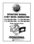
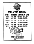
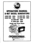
/ OPERATORS MANUAL··
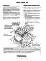
D-NET DIESEL GENERATORS .
. SINGLE AND
THREE PHASE
..... i '.
.'
.
8.0KW - 60Hz EDT - 12.5KW - 60Hz EDT
6.0KW - 50Hz EDT' 9.4KW - 50Hz EDT'
. 10.0KW - 60Hz EDT
7.5KW- 50Hz EDT
12.6KW - 60Hz EDT
10.4KW • 50Hz~EDT
~>"
.
.-
,
!
.
11.5KW- 60Hz EDT . 15.0KW -60Hz EDT
9.2KW . 12.0K"\L·~ 50Hz EDT
.
-~-.
NO.053060
REVISION FOUR
. -.- ___ =--__
"V§
member
~JrJlr
;;J!I!.
.
!~~.22!!.,-011- '
I
~
__ • ____ '~ ___ ·e __ ~ ______
, . , ___ ~~ __,-,~",~~_-.,'
,-
~
•
WESTERBEKE
WESTERBEKE CORPORATION. MYLES STANDISH INDUSTRIAL PARK
150 JOHN HANCOCK ROAD. TAUNTON, MA 02780·7319 U.S.A.
TEL: (508)823-7677· FAX: (508)884-9688· WEBSITE: www.WESTER8EKE.COM
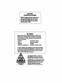
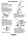
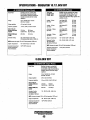
CALIFORNIA
PROPOSITION 65 WARNING
Diesel engine exhaust and some
of its constituents are known to
the State of California to cause
cancer, birth defects, and other
.
reproductive harm.
A WARNING:
Exhaust gasses contain Carbon Monoxide, an odorless and
colorless gas. Carbon Monoxide Is poisonous and can,cause
unconsciousness and death. Symptoms of Carbon MonoxIde
exposure can Include:
- Throbbing in Temples
- DIzziness
-Nausea
- Muscular Twitching
-Headache
- Vomiting
- Weakness and Slfleplness -Inability to Think CoheTl/ntly
IF YOU OR ANYONE ELSE EXPERIENCE ANY OF THESE SYMPTOMS,
GET OUT INTO THE FRESH AIR IMMEDIATELY. If symptoms persist,
seek medical attention. Shut down the. unit and do not restart
until it has been inspected and repaired.
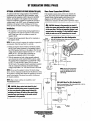
This WARNING DECAL is provided by
WESTERBEKE and should be fixed to a
bulkhead near your engine or generator.
WESTERBEKEalso recommends installing
CARBON MONOXIDE DETECTORS in the
living/sleepIng quarten; of your vessel.
They aTl/inexpenslve and easily
obtainable at your local marine stOTl/.
SAFETY INSTRUCTIONS
PREVENT BURNS - FIRE
INTRODUCTION
Read this safety manual carefully. Most accidents are
caused by failure to follow fundamental rules and precau·
tions. Know when dangerous conditions exist and take the
necessary precautions to protect yo,:,rse/f, your personne4
and your machinery.
The following safety instructions are in compliance with
the American Boat and Yacht Council (ABYC) standards.
•
PREVENT ELECTRIC SHOCK
•
A WARNING: Fire can cause injury or death!
A WARNING: Do not touch AC electrical connections
•
while engine is runnIng, or when connected to shore
power. Lethal voltage is present at these connections!
•
•
Do not operate this machinery without electrical
enclosures and covers in place.
• Shut off electrical power before accessing electrical
equipment.
• Use insulated mats whenever working on electrical
equipment.
• Make sure your clothing and skin are dry, not damp
(particularly shoes) when handling electrical equipment.
• Remove wristwatch and all jewelry when working on
electrical equipment.
• Do not connect utility shore power to vessel's AC
circuits, except through a ship-to-shore double throw
transfer switch. Damage to vessel's AC generator may
result if this procedure is not followed.
• Electrical shock results from handling a charged capacitor. Discharge capacitor by shorting terminals together.
•
Prevent flash fires. Do not smoke or permit flames or
sparks to occur near the carburetor, fuel line, filter, fuel
pump, or other potential sources of spilled fuel or fuel
vapors. Use a suitable container to catch all fuel when
removing the fuel line, carburetor, or fuel filters.
Do not operate with a Coast Guard Approved flame
arrester removed. Backfire can cause severe injury or
death.
Do not operate with the air cleaner/silencer removed.
Backiire can cause severe injury or death.
Do not smoke or permit flames or sparks to occur near
the fuel system. Keep the compartment and the
engine/generator clean and free of debris to minintize the
chances of fire. Wipe up all spilled fuel and engine oil.
Be aware - diesel fuel will burn.
PREVENT BURNS - EXPLOSION
A WARNING: Explosions from fuel vapors can cause
injury or death!
• Follow re-fueling safety instructions. Keep the vessel's
hatches closed when fueling. Open and ventilate cabin
after fueling. Check below for fumes/vapor before running the blower. Run the blower for four ntinutes before
starting your engine.
• All fuel vapors are highly explosive. Use extreme care
when handling and storing fuels. Store fuel in a well-ventilated area away from spark-producing equipment and
out of the reach of children.
• Do not fill the fuel tank(s) while the engine is running.
• Shut off the fuel service valve at the engine when serviciitg
the fuel system. Take care in catching any fuel that ntight
spill. DO NOT allow any smoking, open flames, or other
sources of fire near the fuel system or engine when servicing. Ensure proper ventilation exists when servicing the
fuel system.
• Do not alter or modify the fuel system.
• Be sure all fuel supplies have a positive shutoff valve.
• Be certain fuel line fittings are adequately tightened and
free of leaks.
• Make sure a fire extinguisher is installed nearby and is
properly maintained. Be familiar with its proper use.
Extinguishers rated ABC by the NFPA are appropriate
for all applications encountered in this enviroinnent. .
PREVENT BURNS - HOT ENGINE
A WARNING: Do not touch hot engine parts or
exhanst system components. A running engine gets
very hot!
• Always check the engine coolant level at the coolant
recovery tank.
A WARNING: Steam can cause inj~~ or death!
• In case of an engine overheat, allow the engine to cool
before touching the engine or checking the coolant.
-.v: WESTERBEKE
Engines & Generators
i
SAFETY INSTRUCTIONS
ACCIDENTAL STARTING
TOXIC EXHAUST GASES
A WARNING: Accidental starting can cause injury
A WARNING: Carbon monoxide (CO) Is a deadly gas!
Dr death!
• Ensure that the exhaust system is adequate to expel gases .
discharged from the engine. Check the exhaust system
regularly for leaks and make sure the exhaust manifolds
are securely attached and no warping exists. Pay close
attention to the manifold, water injection elbow, and
exhaust pipe nipple.
• Be sure the unit and its surroundings are well ventilated.
• In addition to routine inspection of the exhaust system,
install a carbon monoxide detector. Consult your boat
builder or dealer for installation of approved detectors.
• For additional information refer to ABYC T-22 (educational information on Carbon Monoxide).
•
Disconnect the battery cables before servicing the engine!
generator. Remove the negative lead first and reconnect
it last.
• . Make certain all personnel are clear of the engine before
starting.
• Make certain all covers, guards, and hatches are reinstalled before starting the engine.
BATTERY EXPLOSION
A WARNING: Battery explosion can cause Injury
Dr death!
A WARNING: Carbon monoxide (CO) is an invisible
•
Do not smoke or allow an open flame near the battery
being serviced. Lead acid batteries entit hydrogen, a
highly explosive gas, which can be ignited by electrical
arcing or by lit tobacco products. Shut off all electrical
equipment in the vicinity to prevent electrical arcing during servicing.
• Never connect the negative (-) battery cable to the positive (+) connection terntinal of the starter solenoid. Do
not test the battery condition by shorting the terntinals
together. Sparks could ignite battery gases or fuel vapors.
Ventilate any compartment containing batteries to prevent
. accumulation of explosive gases. To avoid sparks, do not
disturb the battery charger connections while the battery
is being charged.
• Avoid contacting the terminals with tools, etc., to prevent
bums or sparks that could cause an explosion. Remove
wristwatch, rings, and any other jewelry before handling
the battery.
• Always tum the battery charger off before disconnecting
the battery connections. Remove the negative lead first
and reconnect it last when disconnecting the battery.
odorless gas. Inhalation produces flu-like symptoms,
nausea or death!
•
Do not use copper tubing in diesel exhaust systems. Diesel
fumes can rapidly destroy copper tubing in exhaust systems. Exhaust sulfur causes rapid deterioration of copper
tubing resulting in exhaust/water leakage.
• Do not install exhaust outlet where exhaust can be drawn
through portholes, vents, or air conditioners. If the engine
exhaust discharge outlet is near the waterline, water could
enter the exhaust discharge outlet and close or restrict the
flow of exhaust. Avoid overloading the craft.
• Although diesel engine exhaust gases are not as toxic as
exhaust fumes from gasoline engines, carbon monoxide
gas is present in diesel exhaust fumes. Some of the symptOllis or signs of carbon monoxide inhalation or poisoning
are:
Vontiting
Dizziness
Throbbing in temples
Muscular twitching
Intense headache
Weakuess and sleepiness
BATTERY ACID
A WARNING: SulfuriC acid In batteries can cause
severe injury Dr death!
AVOID MOVING PARTS
• When servicing the battery or checking the electrolyte
level, wear rubber gloves, a rubber apron, and eye protection. BatterIeScontain sulfuric acid which is destructive.
If it comes in contact with your skin, wash it off at once
with water. Acid may splash on the skin or into the eyes
inadvertently when removing electrolyte caps.
~
A WARNING: Rotating parts can cause injury
Dr death!
• Do not service the engine while it is running. If a situation arises in which it is absolutely necessary to make.
operating adjustments, use extreme care to avoid touching moving parts and hot exhaust system components.
WESTERBEKE
Engines & Generators
ii
SAFETY INSTRUCTIONS
Do not wear loose ~Iothing or jewelry when servicing
equipment; tie back long hair and avoid wearing loose
jackets, shirts, ,sleeves, rings, necklaces or bracelets that
could be caught in moving parts.
• Make sure all attaching hardware is properly tightened.
Keep protective shields and guards in their respective
places at all times.
• Do not check fluid levels or the drive belt's tension while
the engine is operating.
• Stay clear of the drive shaft and the transmission coupling
when the engine is running; hair and clothing can easily
be caught in these rotating parts.
•
HAZARDOUS NOISE
A WARNING: High noise levels can cause hearing
loss!
•
•
•
Never operate an engine without its muffler installed.
Do not run an engine with the air intake (silencer)
removed.
Do not run engines for long periods with their enclosures
open.
A WARNING: Do not work on machinery when you are
ABYC, NFPA AND USCG PUBLICATIONS FOR
INSTALLING DIESEL ENGINES
Read the following ABYC, NFPA and USCG pUblications
for safety codes and standards. Follow their recommendations when installing your engine.
ABYC (American Boat and Yacht Council)
"Safety Standards for Small Craft"
Order from:
ABYC
15 East 26th Street
New York, NY 10010
NFPA (National Fire Protection Association)
"Fire Protection Standard for Motor Craft"
Order from:
National Fire Protection Association
11 Tracy Drive
Avon Industrial Park
Avon, MA 02322
USCG (United States Coast Guard)
"USCG 33CFR183"
Order from:
U.S. Government Printing Office
Washingt?n, D.C. 20404
mentally or physically Incapacitated by fatigue!
OPERATORS MANUAL
Many of the preceding safety tips and warnings are repeated
in your Operators Manual along with other cautions and
notes to highlight critical information. Read your manual
carefully, maintain your equipment, and follow all safety
procedures.
ENGINE INSTALLATIONS
Preparations to instail an engine should begin with a thorough examination of the American Boat and Yacht Council's
(ABYC) standards. These standards are a combination of
·sources including the USCG and the NFPA.
Sections of the ABYC standards of particular interest are:
H-2 Ventilation
P-l Exhaust systems
P-4 Inboard engines
E-9 DC Electrical systems
All installations must comply with the Federal Code of
Regulations (FCR).
Engines & Generators
iii
INSTALLATION
When installing WES1ERBEKE engines and generators it is important that strict
attention be paid to the following information:
CODES AND REGULATIONS
Strict federal regulations, ABYC guidelines, and safety codes must be complied with
when installing engines and generators in a marine environment.
SIPHON-BREAK
For installations where the exhaust manifold/water injected exhaust elbow is close to
or will be below the vessel's waterline, provisions must be made to install a siphonbreak in the raw water supply hose to the exhaust elbow. This hose must be looped.a
ntinirnum of 20" above the vessel's waterline. Failure to use a siphon-break when
the exhaust manifold injection port is at or below the load waterline will result in
raw water damage to the engine and possible flooding of the boat.
If you have any doubt about the position of the water-injected exhaust elbow relative
to the vessel's waterline under the vessel's various operating conditions} install a
siphon-break.
NOTE: A siphon-break requires periodic inspection and cleaning to ensure proper
operation. Failure to properly maintain a siphon-break can result in catastrophic
engine damage. Consult the siphon-break manufacturer for proper maintenance.
EXHAUST SYSTEM
The.exhaust hose must be certified for marine use. The system must be designed to
prevent water from entering the exhaust under any sea conditions and at any angle
of the vessels hull.
Adetailed Marine Installation Manual covering gasoline and diesel
engines and generatolS is supplied with every unit sold. This manual
.is also available in pdf format on our website to download
Website: www.westerbeke.com
· "~IWESTERBEKE
. I Enoines & Generators
iv
AVAILABLE FROM
YOUR WESTERBEKE
OEALER
TABLE OF CONTENTS
Parts Identification ....................................................2
Introduction ................................................................3
Fuel Injection limingl ..............................................28
Preparation ............................................................. 28
Inspection ............................................................ ,,28
Adjustment ............................. :.............................. 28
Glow Plugs ................................................................29
Starter Motor ............................................................30
Emergency Start ................................................... .31
Service .................................................................. .31
Alternator Testing .....................................................32
Voltage Regulator .... :............................................. 32
Checking the Service Battery ................................ 34
Battery Care ........................................................... 34
Warranty Procedures ............................................... 3
Serial Number Location ........................................ ..4
Fuel, Engine 011, and Engine Coolant.. ...................... 5
Digital Control Panel ..................................................6
LCD Sequence ...................................................... 6A
Internal Components ............................................... 7
Remote Stop/Start Panel.. ........................................ 8
Preparations for Initial Start-Up ................................9
Pre-Start Inspection ................................................. 9
Generator Voltage .................................................... 9
Generator Break-In Procedure ................................. 10
Daily Operation ......................................................... 19
Safety Shutdown Switches ............................ :.......... 10
Higb Exhaust Temperature Switch ........................ 11
DC Circuit Breaker .... :........................................... 11
Oil Pressure Sensor.. .............................................. 11
Coolant Temperature Sensor ............................ :.... 11
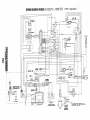
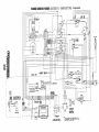
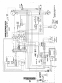
Wiring Diagrams
#54193 ................................................................... 35
#54655 - 24V ..................................................... .35A
#53477 - 24V ...................................................... 35B
#54628 ................................................................ 35C
#54680 - 24V ...................................................... 35D
#52793 .................................................................. .36
Generator Information .............................................. 37
BT Generator............................................................. 38
Six and Twelve Stud lIIustrations .............................38
BT Generator/Single Phase (6 Stud) ............... " ...... .39
Internal Wiring Diagram ........................................... 39
Generator Voltage Adjustment.. .............................. .40
Six Stud Voltage Connections .............................. .40
Twelve Stud Voltage Adjustment ...................... .40A
No-Load Voltage Adjustment ............................ :.',,41
Full Load Voltage Adjustment.. ............................ .41
AVR - Six Stud .................................................... ..42
BT Generator Single Phase .. ,................................ 42
Shore Power Connections ........................................42
BT Generator AVR (Three Phase) ............................ .43
Internal Wiring Diagram .......................................... .44
Regulator Sensing Three Phase .............................. .45
Internal Wiring Diagram (12 Stud) .......................... .46
BT Generator Troubleshooting Chart .......................47
Specifications (3 Cylinder Engine) ........................ .48
8.0/B.OKw - 10.0/7 .5Kw ............................................ 49
11.5/9.2Kw - 12.B/1 0.4Kw ........................................50
Specifications (4 Cylinder Engine) ......................... 51
12.5/9.4Kw - 15.0/12.0Kw........................................ 52
,Lay-Up and RecommiSSioning ..................................53
Power Take-Off ......................................................... 55
Raw Water Discharge Hose ........................,.............56
Water Heater ............................................................ .57
Metric Conversion Data ................ :........................... 58
Suggested Spare Parts .............................................59
Break-In Procedure/Daily Operation ..................... l1A
Maintenance Schedule .............................................12
Cooling System ......................................................... 14
Changing Coolant .................................................. 14
Thermostat ............................................................. 15
Raw Water Cooling Pump ............................ ,........ 15
Changing the Raw Water Impeller ........................ 16
Heat Exchanger ..................................................... 16
Air Intake/Silencer .................................................... 17
Fuel System .............................................................. 18
Fuel LiftlWater Separator ...................................... 18
Fuel Lift Pump ...................................................... 18
Fuel Lift Pump Filter ............................................. 18
Fuel Filter .............................................................. 18
Engine Lubricating Oil .............................................. 19
Engine Oil Change ................................................ 19
Oil Pressure ..............................................................20
Testing Oil Pressure ............................................... 20
Remote Oil Filter ......................................................21
Engine Troubleshooting (Chart) .............................. .22
LCD Display Faults....................................................23
Engine Adjustments ..................................................24
Drive Belt Adjustmen ............................................ 24
Electronic Governor .............................................. 24
Valve Clearance ..................................................... 25
Testing Engine Compression ................................. 26
.Fuel Injecto~s ... "-.. "- ... ,., .. " ......................................,29
Fuel Injectors · ..................:................,.............................27
Injector Testing :..................................................... 28
Spray Pattern .......................................................... 28
~
WESTERBEKE
EngInes & Generators
1
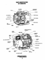
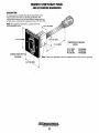
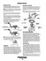
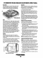
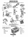
PARTS IDENTIFICATION
EDT GENERATOR
LEFT SIDE
OIL
I.O.PLATE
~A:I-+--·EXH.AUST ELBOW
DC ALTEIINAT~IR--':'__ ,
DlL DRAIN
iM'~------I--I---""';SlrART SOLENOID
RAW WATER PUMP _ _ _ .,
GENERATOR
BACKEND
-'OT'.OTtO
MOTOR
HEAT
REAR
MANIFOLD PRESSURE CAP
FILL
PREHEAT
RIGHT SIDE
THERMOSTAT
ASSEMBLY
CONTROL
PANEL
20A DC CIRCUIT
AIR INTAKE
SILENCER & FILTER
BRE/\KE~:---r~Q
ENGINE BLOCK DRAIN PLUG
OIL DRAIN HOSE .
AC
BREAKER
OIL
FRONT
REAR
I
FUEL FILTER
MOUNT·
~
WESTERBEKE
Engines & Generators
2
INTRODUCTION
This WESTERBEKE Diesel Generator is a product of
WESTERBEKE's long years of experience and advanced
technology. We take great pride in the superior durability and
dependable perfonnance of our engines and generators.
Thank you for selecting WESTERBEKE.
In order to get the full use and benefit from your generator it
is important tbat you operate and maintain it correctly. This
manual is designed to help you do this. Please read this
manual carefully and observe all the safety precautions
throughout. Should your generator require servicing, contact
your nearest WESTERBEKE dealer for assistance.
This is your operators manual. A parts catalog is also
provided and a technical manual is available from your
WESTERBEKE dealer. If you are planning to install this
equipment contact your WESTERBEKE dealer for
WESTERBEKE'S installation manual.
WARRANTY PROCEDURES
Your WESTERBEKE Warranty is included in a separate
folder. If, after 60 days of submitting the Warranty Registry
fonn you have not received a customer identification. card
registering your warranty, please contact the factory In
writing with model infonnation, including the unit's serial
. number and commission date.
Customer Identification Card
,...".."WESTERBEKE
j Engines & Generators
PRODUCT SOFTWARE
product software, (tech data, parts lists, manuals,
brochures and catalogs), provided from sources other than
WESTERBEKE are not within WESTERBEKE's control.
WESTERBEKE CANNOT BE RESPONSIBLE FOR THE
CONTENT OF SUCH SOFTWARE, MAKES NO WARRANTIES OR REPRESENTATIONS WITH RESPECT
THERETO, INCLUDING ACCURACY, TIMEliNESS OR
COMPLETENESS THEREOF AND WILL IN NO EVENT
BE UABLE FOR ANY TYPE OF DAMAGE OR INJURY
INCURRED IN CONNECTION WITH OR ARISING OUT
OF THE FURNISHING OR USE OF SUCH SOFTWARE.
WESTERBEKE customers should also keep in mind the
time span between printings of WESTERBEKE product
software and the unavoidable existence of earlier
WESTERBEKE manuals. In summation, product software
provided with WESTERBEKE products, whether from
WESTERBEKE or other suppliers, must not and cannot
be relied upon exclusively as the definitive authority on
the respective product. It not only makes good sense
but is imperative that appropriate representatives of
WESTERBEKE or the supplier in question be consulted
to determine the accuracy and currentness of the
product software being consulted by the customer.
NOTES, CAUTIONS AND WARNINGS
As this manual takes you through the operating procedures,
maintenance schedules, and troubleshooting of your marine
engine, critical infonnation will be highlighted by NOTES,
CAUTIONS, and WARNINGS. An explanation follows:
Customer Identification
MR. GENERATOR OWNER
MAIN STREET
HOMETOWN, USA
Ser.#
Model
Expires
NOTE: An operating procedure essential to note.
A CAUTION: Procedures, which If no.' strictly
obseflled, can result in the damage or destruction of
your engine.
A WARNING: Procedures, which If not properly fol·
lowed, can result in personal Injury or loss of life.
Engines & Generators
3
•
INTRODUCTION
NOTE: A carbon monoxide warning decallws been provided
SERIAL NUMBER LOCATION
.The units's model number and serial number are located on a
nameplate that is mounred on the side of the engine's water
jacketed exhaust manifold. The engine's serial number can
also be found stamped into the engine block on the flat
surface of the block just above the manual shut-off lever.
Please take the time to enter this information on the
ill\!~tration of the nameplate below. This information will
proVide a quick reference when seeking technical /
information and/or ordering spares/repair parts. Jl:n
by WESTERBEKE. Affix this decal in a visible position in the
engine room.
UNDERSTANDING THE DIESEL ENGINE
The diesel engine closely resembles the gasoline engine,
since the mechanism is essentially the same. The cylinders
are arranged above a closed crankcase; the crankshaft is of
the same general type as that of a gasoline engine; and the
diesel engine has the same type of valves, camshaft, pistons,
connecting rods and lubricating system.
Therefore, to a great extent, a diesel engine requires the
same preventive maintenance as a gasoline engine. The
most important factors are proper ventilation and proper
maintenance of the fuel, lubricating and cooling systems.
Replacement of fuel and lubricating filter elements at the
time periods specified is a must, and frequent checking for
contamination (that is, water, sediment, etc.) in the fuel
system is also essential. Another important factor is the use
of the same brand of high detergent diesel lubrication oil
designed specifically for diesel engines.
The diesel engine does differ from the gasoline engine,
however, in its method of handling and firing of fuel. The
carburetor and ignition systems are done away with and in
their place is a single component - the fuel injection pump
which performs the function of both.
ORDERING PART$Whenever replacement/service parts are needed, always
provide the generator model number, engine serial number,
and generator serial number as they appear on the silver and
black name plate located on the generator end. You must
provide us with this information so we may properly identify
your generator set In addition, include a complete part
description and part number for each part needed (see the
separately furnished Parts List). Also insist upon
WESTERBEKE packaged parts because will fit or generic
parts are frequently not made to the same specifications as
original equipment.
SPARES AND ACCESSORIES
Certain spares will be needed to support and maintain your
WESTERBEKE generator. Your local WESTERBEKE
dealer will assist you in preparing an inventory of spare parts.
See the SPARE PARTS page in this manual. For Engine and
Generator AccessoLies, see the ACCESSORIES brochure.
An identification ptate on the engine manifold also displays
the engine model and seLial number.
INSTALLAtiON. MANUAL
Publication #43400 provides detailed information for
installing generators.
CARBON MONOXIDE DETECTOR
WESTERBEKE recommends mounting a carbon monoxide
detector in the vessels living quarters. Carbon monoxide,
even ill small amounts, is deadly.
The presence of carbon monoxide indicated an exhaust leak
from the engine or generator or from the exhaust
elbow/exhaust hose, or the fumes from a nearby vessel are
entering your boat.
If carbon monoxide is present, ventilate the area with clean
air and correct the problem inunediately!
EngInes & Generators
4
DIESEL FUEL, ENGINE OIL AND ENGINE COOLANT
DIESEL FUEL
ENGINE COOLANT
USE A DIESEL FUEL WITH ACETANE RATING OF #45 OR HIGHER.
WESTERBEKE recommends a mixture of SO% antifreeze
and SO% distilled water. Distilled water is free from the
chemicals that can corrode internal engine surfaces.
The antifreeze performs double duty. It allows the engine to
run at proper temperatures by transferring heat away from
the engine to the coolant, and lubricates and protects the
cooling circuit from rust and corrosion. Look for a good
quality antifreeze that contains Supplemental Cooling
Additives (SCAs) that keep the antifreeze chemically
balanced, crucial to long tenu protection.
The distilled water and antifreeze should be premixed before
being poured into the cooling circuit.
(No. 2-D (SAE J313) diesel fuel according to ASTM D975}.
Care Of The Fuel Supply
Use oi1ly clean diesel f'uel! The clearance of the components
in your fuel injection pump is very critical; invisible dirt·
particles which might pass through the filter can damage
these finely finished parts. It is important to buy clean fuel,
and keep it clean. The best fuel can be rendered
unsatisfactory by careless handling or improper storage
facilities. To assure that the fuel going into the tank for your
engine's daily use is clean and pure, the following practice is
advisable:
Purchase a well-known brand of fuel.Instail and regularly
service a good, visual-type fuel filter/water separator· between
the fuel tank and the engine. The Raycor SOO MA or 230
RMAM are good examples ,of such filters.
ENGINE OIL
Use a heavy duty engine oil with an: API classification of CP,
CG-4, CH-4 or CI-4. Change the engine oil and filter after an
initial SO hours of break-in operation. Then follow the oil and
filter change intervals as specified in the MAINTENANCE
SCHEDULE in this manual. Westerbeke Corporation does
not approve or disapprove of the use of synthetic oils. If
synthetic oils are used, engine break-in must be perfonued
using conventional oil. Oil change intervals must be as in the
MAINTENANCE SCHEDULE, not extended because
synthetic oils are used.
PURCHASING ANTIFREEZE
Rather than preparing the mixture, WESTERBEKE
recommends buying the premixed antifreeze so that so that
when adding coolant the mixture will always be correct.
There are two common types of antifreeze, Ethylene Glycol
(green) and Propylene Glycol (redlpurple), either can be used
but do not mix the two and if changing from one to another,
flush the engine thoroughly.
Premixed antifreeze for DIESEL Engines:
Specification #ASTM D53456.
MAINTENANCE
Change the engin" coolant every five years regardiess of the
number of operating hours as the chemical additives that
protect and lubricate the engine have a limited life.
COOLANT RECOVERY TANK
SAE OIL VISCOSITY GRADES
A coolant recovery tank kit is supplied with each
engine or generator. The purpose of this recovery tank is to
allow for engine coolant expansion and contraction during
engine operation, without the loss of coolant and without
introducing air into the cooling system. This kit is provided
and must be installed before operating' the engine.
For alliemperalures use SAE 10W-30 or 15W-40.
OIL PRESSURE
The engine's oil pressure, during operation, is indicated
by the oil pressure gauge on the instrument panel. During
normal operation, the oil pressure will range between 3S and
65 psi 2.S and 3.9 kg/em').
NOTE: This tank, with its short run ofplastic hose, is best
located at or above the level of the engine's manifold, but it
can be located below the level of the engine's manifold if the
particular installation makes this i'lecessary.
- .
.
NOTE: A newly started, cold engine can have an oil pressure
reading upwards of 60 psi (4.2 kg/cm'). A warmed engine can
have an oil pressure reading as low as 25 psi -(1.8 kg/em".
These readings will varj depending upon the temperature of
the engine, the load placed on the engine, and the RPM~.
....v"
WESTERBEKE
Engines & Generators
5
'
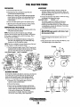
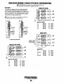
DIGITAL CONTROL PANEL
DESCRIPTION·
. LCD DISPLAY.
WESTERBEKE~ S Digital
Control Panel provides the
operator with an LCD display that contunuously monitors
all the operations of the generator in easy to understand
Operating temperatures may cause the LCD display to vary
in color. This is normal and a change in color will not affect
the operation on the control Panel.
Periodically clean the control panel LCD screen using a soft
cloth.
text messag~s.
CONTROL BOX
. UP AND DOWN ARROWS
WHEN THE LCO DISPLAY IS
IN ITS SCROLL MODE, THE
UP AND DOWN ARROWS CAN
BE USED TO AOJUST THE
DARK AND LIGHT CONTRAST
Note that the design and size of the control box will vary .
dependin~ on the model generator.
UP-ARROW
WHEN IN SCROLL LOCK MODE
INOIVIDUAl FUNCTIONS CAN
BE MONITOREO BY PRESSING
THE UP-ARROW.
SA F.USE
PROTECTS THE CONTROL PANEL
ELECTRONICS FROM A HIGH
AMPERAGE OVERLOAD.
SCROLL LDCK
STOPS RUN SEQUENCE 81); .
THAT A SINGlEFUNCTfOlicAN.
BE MONITORED
INDICATOR LIGHTS
SIX LIGHTS THAT INO/CATI~
WHERE A FAULT HAS OCCURED..
DOWN-ARROW
WHEN IN SCROLL LOCK MODE
INDIVIDUAL FUNCTIONS CAN
. BE MONITORED BY PRESSING
THE DOWN-ARROW.
~
20A BREAKER SWITCH "SHUT-OFF WHEN PERFORMING
MAINTENANCE OR WHEN·
REPAIRING A FAULJ RESET TO
RESTART THE ENGINE.
FAILURE LIGHT .
A REO LIGHT WILL APPEAR IF
THE RUN SEQUENCE IS
INTERUPTEO BY A FAILURE.
PRIME BUTTON
START BUTTON
STARTS THE ENGINE
THIS BUTTON ENERGIZES THE FUEL
PUMP. AFTER REPAIRING A FAILURE
OR PERFORMING MAINTENANCE,
PRESSING THIS BUTTON WILL PURGE
AIR OUT AND BRING FUEL IN TO THE
LINES.
LCD DISPLAY SEIlUENCE
..
IS SHOWNDN THE FOLLOWING PAGE .,.
*MANUAL ENGINE SHUT·OFF
Should the stop button fail in its normal function to stop the
engine, the engine is equipped with a manual shutdown lever,
located on the engi!\eQlock to the left of the side oil fill.
Simply hold down the lever to the left until the engines
comes.to a. complete stop . .This shutdown lever is standard on
..
.
current D-Net generators, ..'
~anU~IEngine
'.
ShutOff·
Engines & Generators
6
SHUT-DOWN LEVER
SIDE Oil FILL
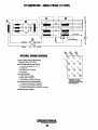
DIGITAL CONTROL PANEL/LCD SEQUENCE
START SEQUENCE
STOP SEQUENCE
With the pre-start inspection .completed, press the START
button and'the antomatic sequence will begin. The six
indicator lights ,will illuminate green and the panel will
display, the following text:
To stop the generator, press the STOP button. The display
will cycle thru the following text messages arid shutdown.
Shutting'
'Down "
'Waiting 'for operator
Engine Shutdown
Press start to
'engage generator
Wailing for operator
Press slart to
engage generator
Pre Heating......
7 Seconds
Cranking ...... ,
FAILURE LIGHT/SHUTDOWN
RUN SEQUENCE"-
If a problem occurs, the generator will shutdown and the
FAILURE light will illuminate red. In addition, one of the
indicator lights will change from green to orange to reveal
where the trouble has occured and the display will text
message what has happened.
Examples:
,..-------"
High Engine Temp.
Failure Light is red.
As the display cycles thru the engine functions, the speed
will come up to 1800 rpms-60Hz (1500 rpms,50Hz) and
the oil pressure and engine coollljlt will rise to their normal
readings. The functions will cycle in the following sequemce:
, .-<.
,Coolani Temperaiure
'Engine Speed
1~OO
81C
32· ...
RPM
250d'
0
-_.-
--
~Q~9l_l
'
-'.
VDC
30
,.
-
Oil Pressure . ,
"40
I
0
0
60,1Hz
AC Phase Voltage
A120V
'B 120V'
0
SCROLL
2ml
120V
i
2c o
0
~D~
St;RO~~
SCROLL
AC Phase Voltage'
AB :lilO
.'
vO
"Ii'"
'BC,378V, ,
o
CA380,V
SCROLL LOCK
100
At LineVoltage
.~
',or
600
i
. . 600
I.
SCROLL
.
When a failure occurs, refer to the troubleshooting chart,
wirlog diagram, and general operating text in this manual to
assist in solving the trouble.
There are many combinations of messages that can be
displayed but they are all self explanatory and the operator
can easily isolate and correct the problem should 011e occur.
Before r.,.s!artin&, the generator, the 20 amp DC circili~ .
breaker l"ust be r'f.sekWith lhe problem corrected an~'-the
generator'started, the'sequences will begin cycling again.
i
..... SC~OlL
Low Oil Pressure
Oil Pressure Light is or~nge. Resel ECU to Restart
.6,9
SCROLL
' AC Frequency
3.8 HOURS
,
, Failure Light is red.
PSI-'
,11m
5.CROLl
Engine Hours
Reset ECU to Restart'
SCROLL
0,
I
0
"
3.1
:B1\R'
Coplan:! Teniperatu.re Light
is oran'ge..
1(i~'
0
Battery Voltage,
13.5
178F
300"
, Ac Line Voltage
;!
'-'~oo
AB380\fr'
'
I m
......._ .. '600
i ::r
BC378V':
o
" . 600
i
CA380V
,"LOCK 1\l'
"'
¢'
NOTE: Three phase voltages will vary d,epending.on the AC
output configuration of the generator.
.,"
,
,
"
To stop the continuing sequence, press the SCROLL LOCK
button, This enables the operator to monitor a single function
for any length of time. The word LOCK will appear in ,the
corner. Use the up and down arrows to find and observe other
functions. To resume scrolling, press the SCROLL LOCK
button a g a i n . '
'~ WESTERBEKE
Eng~nes,
& Generators
6A
Controi Box Components
and Frequency Adjustments
are on the following page.
t
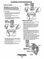
DIGITAL CONTROL BOX
FREQUENCY FAULT
GENERATOR FREQUENCY ADJUSTMENT (HERTZ)
Frequency is displayed on the LCD display screen while the
engine is running in 'RPMandfrequency (hertz).
The ECU is receiving a low AC voltage signal and hertz
signal from the MPU which is positioned on the bellhousing
over the flywheel ring gear teeth. The ECU interprets this
signal as both RPM
and hertz.
.
.
".
CAUTION: When changing the generator frequency setting on
the ECU, tum off the 20 amp DC circuit breaker on the control
box. Tum it back on tifter the setting has been changed
NOTE: If the unit shuts down for an underspeed condition, the
same fault "overspeed" will show on the screen but the
. frequency LED will BliNK.
shouid this signal vary approximately 2% eit\ler up or down,
a frequency fault shut down will occur, initiated by the ECU.
The red failure LED on the display panel. will illuminate, the
frequency LED will tum from green to amber and the LCD
display screen will show the fault text "overspeed".
1. T\lm the DC breaker on the control panel to the OFF
position.
2. Open the cover of the control box and view the ECU
(EI.,tronic Control Unit).
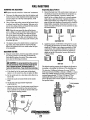
3. Locate the #1 dipswitch on the ECU and move it to the
.position that corresponds to the Herl2 operation desired).
See the illustration below showing the ECU in the
control box.
4. Replace the control box cover, tum the DC breaker ON
and start the unit. Monitor the frequency that the
engine/generator is operating is operating at ihe correct
fn,quency.
NOTE: If the unit shuts down for an underspeed condition, the
same fault "overspeed" will show on the screen but the
frequency LED will BliNK.
WHEN CHANGING THE GENERATORS
. FREQUENCY (50160 HZ) SWITCH #1
ON THE CONTROL PANEL ECU
BOARD MUST BE SWITCHED:
...ON FOR 50 HZ AND OFF FOR 60 HZ.
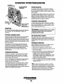
CONTROL BOX
INTERNAL CoM!PoNiENTS
~~~;AMPDC
BREAKER
NOTE: DURING OPERATION THE COLOR
OF THE LCD DISPLAY MAY VARY.
CAUSED BY HEAT. THIS IS NORMAL
AND NO CAUSE FOR CONCERN.
CAUTION (WESTERLINK or NMEA-2DDO): The electronic components in the Digital Diesels draw a very small amount of amperage (milli-amps)jrom the
generator:S starting battery when.th~.unit is in a static state. This maybe as much as 50 milli-ampsfor the system ECU and SO milli-ampsjor each display.
This can be as much as 72 amp-hours in a months. time with no g~nerator use. It is not necessary to be concerned with this slight amperage draw during
normal.seasonal use. However. if the generator set is not to be usedfor a number ojmonths, such as winter storage, it is best to disconnect the DC power
to the generator with a NMEA-2009 system or shut off the DC breaker qn the generator's control boxfor a WESTERLlNK system.
.
NOTE: Keep in mind that the Westerbeke generator maybe the DC power supply for the vessel's NMEA-2000 network.
~
WESTERBEKE
Engines & Generators
7
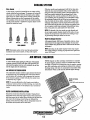
REMOTE STOP/START PANEL
AND EXTENSION HARNESSES
DESCRIPTION
A remote panel is availa\>le that allows the generator to be
stopped and started from any location on the boat. The
connecting harnesses come in three different lengths and two
of these can be combined for a maximum run at 75' (22.17M).
NOTE: For additional injonnation, contact your local
WESTERBEKE dealer.
3'1/4" ,"'.:)0""1111
;6" (152.4MMI
CONNECTING EXTENSION
CABl.ES
15' (4.75M)
30' (9.1M)
60' (18.2M)
PN 052560
PN 052959
PN 052789
PN 052960
.Note: These two dimensions are the measurement of the cut-out opening.
-...v WESTERBEKE
Engines & Generators
8
PREPARATIONS FOR INITIAL STARTUP
PRESTART INSPECTION
This section of the manual provides the operator with
preparation, initial starting, break-in, starting (wann or cold)
and stopping procedures. Follow the procedures as presented
for the conditions indicated and your WESTERBEKE
generator set will give reliable performance and long service
life.
Before starting your generator set for-the rust time or after a
prolonged layoff, check the following items:
Check the engine oilleve!. Add oil to maintain the level at
the high mark on the dipstick.
Check the fuel supply and examine the fuel filter/separator
bowls for contaminant's.
Check the DC electrical system. Inspect wire connections
and battery cable connections. Make certaiil the (+)
battery cable is connected to the starter solenoid and the
negative (-) cable is connected to the engine ground stud
(this location is tagged).
Check the coolant level in both the plastic recovery tank
and at the manifold.
Visually examine the unit. Look for loose or missing
parts, disconnected wires, unattached hoses, and check
threaded connections.
Check load leads for correct connection as specified in the
wiring diagrams.
.
Examine air inlet and outlet for air flow obstructio~s ..
Be sure no other generator or utility power is connected to
load lines.
Be sure that in power systems with a neutral line that
the neutral is properly grounded (or ungrounded) as the
system requires, and that generator neutral is properly
connected to the load neutral. In single phase and some
3-phase systems an incomplete or open neutral can supply
the wrong line-to-neutral voltage on unbalanced loads.
Make sure the mounting installation is secure.
Make sure that the generator is properly grounded.
o
o
o
o
o
o
o
o
o
A CAUTION: When starting the generator, it is
recommended that all AC loads, especially large motors,
be switched OFF until the engine has come up to speed
and, in cold climlltes, starts to warm up. This precaution
will prevenr'dllmau.B.Caused by unanticipated operation
of/he AC machliJiJiJt~f1d will prevent a cold engine from
stalling.
; ..
GENERATOR VOLTAGE
The speed of the generator engine is adjusted at the factory,
however, iUs advisable to verify.
. 60 Hz
The engine no-load speed is set at 61.0 - 60.5 Hz.
At rated amperage, hertz output may decrease to
59.5 - 60.0 Hz.
50 Hz
The engine no-load speed is set at 50.0 - 50.3 Hz.
At rated amperage, hertz output may decrease to
49.5 - 50.0 Hz.
The speed of fue-generator engine is ~djusted at the factory,however it is advisable to verify. The voltages are easily
adjusted to optimum values no-load and full load (refer to
VOLTAGE ADJUSTMENT in this manual). If possible, apply
actual service attest load of the same power factor as the
load to be used iii service. If the voltage cannot be adjusted
to suitable v;a''EluiSesllianRdif~auK.lt~seems evident, contact your
authorized '"
PLASTIC RECOVERY
,"M'L_""'"
eH.''''H.CAP
o
o
GLOW
CONNECTION
Oil
SIDE OIL
Engines & Generators
9
CAP
CAP
GENERATOR BREAK-IN PROCEDURE
After the first 10 hours of the generator's operation, llie load
can be increased to the full-load rated output, then periodically vary the load.
Avoid overload at all times. An overload is signaled by smoky
exhaust with reduced output voltage and frequency. Monitor
the current being drawn from the generator and keep it within
the generator's rating. Since the generator operates at 1800
rpm to produce 60 hertz (or at 1500 rpm to produce 50
Hertz), control of the generator's break-in is governed by the
current drawn from the generator.
DESCRIPTION
Although your engine has experienced a minimum of one
hour of test operations at the factory to make sure accurate
assembly procedures were followed and that the engine
operated properly, a break-in time is required. The service
life of your engine is dependent upon how the engine is
operated and serviced during its initial hours of use.
Breaki1)g-in a new engine basically involves seating the
piston rings to the cylinder walls. Excessive oil consumption
and smoky operation indicate that the cylinder walls are
glazed or scored, which is caused by overloading the
engine during the break-in period.
Your new engine requires approximately 50 hours of initial
conditioning operation to break in each moving part in order
to maximize the perfonnance and service life of the engine.
Perfonn this conditioning carefully, keeping in mind the
following:
Start the engine according to the STARTING PROCEDURE
section. Run the engine while checking that all systems (raw
water pump, oil pressure, battery charging) are functioning.
NOTE: Be aware of motor starting loads and the high current
draw required for starting motors. This starting. amperage
draw can be 3 to 5 times rionnal running amperage. 'See
GENERATOR INFORMATION in this manual.
GENERATOR ADJUSTMENTS
Once the generator has been placed into operation
(commissioned), there maybe the need to adjust the
generator:~ no-load AC voltage output. See GENERATOR
INFORMATION.
AFTER START-UP
Once the generator has been started, check for proper operation and then encourage a fast warm-up. Run .the generator
between 20% and 60% of full-load for the first 10 hours.
THE DAILY ROUTINE
CHECK LIST
Follow this check list each day before starting your generator.
• Check that all generator circuit breakers (power panel) are
in the off position before starting.
NOTE: Some unstable running may occur in a cold engine.
This condition should abate as normal operating temperature
is reached and loads are applied.
A CAUTION: Do not operate the generator for long
• Record the hourrneter reading in your log (engine hours
relate to the maintenance schedule.)
periods of time without a load being placed on the
generator.
Any deficiency or problems in the following items must
be corrected before start up.
STOPPING THE GENERATOR
• Visually inspect the engine for fuel, oil, or water leaks.
Remove the AC loads from the generator one at a time.Allow
the generator to run for 3-5 minutes to stabilize the operating
temperatore, then tom the key to the off position. Once the
generator is shutdown, close down all circuit breakers as a
safety precaution.
• Check the oil level (dipstick).
• Check the coolant level in the coolant recovery tank.
• Check your fuel supply.
• Check the starting batteries (weeldy).
• Check drive belts for wear and proper tension (weeldy).
CHECK WITH THE ENGINE RUNNING.
• Check for abnonnal noise such as knocking, vibrating and
blow-back sounds.
• Confinn exhaust smoke:
When the engine is cold - White Smoke.
When the engine is warm - almost Smokeless.
When the engine is overloaded - some Black Smoke.
,..yo
CAUTION {WE~;YERLINK Dr NMEA~20IiO}: The -~ieci~nic components in the
Digital Diesels draw a very small amount of amperage (milli-amps) from
the generator's starting battery when the unit is in a static state. This
maybe as much as 50 milli-amps for the system ECU and 50 milli-amps
jor each display. This can be as much as 72 amp~hours in a months time
with no generator use. It is not necessary to be concerned with this slight
amperage draw during normal seasonal use. However, if the generator
set is not to be used for a number of months, such as winter storage, it is
best to disconnect the DC power to the generator with a NMEA-2000
system or shut off the DC breaker on the generator's control box/or a
, WESTERLINK system.
NOTE: Keep in mind that the Westerbeke generator maybe the DC power
supply for the yessel's NMEA-2000 network.
WESTERBEKE
Engines & Generators
-fO
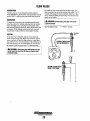
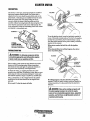
SAFETY SHUTDOWN SWITCHES
....",' _<lno. ENGINE BLOCK
SAFETY SHUTDOWN SWITCHES
The "ENGINE" is protected by four automatic shutdown
switches. Should shutdown occur, do not attempt to restart
before correcting the cause as shown on the LCD Display
screen.
The following is a description of these automatic shutdown
switches.
HIGH EXHAUST TEMPERATURE SWITCH
An exhaust temperature switch is located on the water
injected exhaust elbow. Normally closed contacts, this switch
will open and signal the ECU (shutting off the engine) should
the switch sense a high exhaust temperature (an inadequate
supply of raw water causes a high exhaust temperature in this
mixing elbow). This switch opens at 270°F (ISI°C). This
contact resets at approximately 19soF (126°C).
OIL PRESSURE
EXHAUST ELBOW
OIL PRESSURE
An oil pressure sensor is mounted on the oil manifold for the
engine. It sends a voltage signal to the ECU that is interpreted
as pressure. Should this signal fall below a set point in the
ECu. The ECU will open the K2 run relay shutting the unit
down: It will then display the fault on the LCD Display
screen. Engine oil pressure dropping 10 - 15 psi will cause
this to occur.
HIGH 'V""" •.T-TEMPERATURE
SWITCH
AIR BLeED PETI:OClI,
ENGINE DC CIRCUIT BREAKER
The generator's DC electrical circuit is protected by a control
panel mounted manually resetable rocker type circuit breaker
(20 amps DC). Excessive current draw or DC electrical
.overload anywhere in the control panel wiring or engine
wiring will cause the breaker to trip. In this event the
generator will shut down. The breaker will trip to the off
position indicating this fault and the LCD Display screen will
be off. The DC circuit on the uuit will be inoperative If this
should occur, check and repair the source of the problem..
After repairing the fault, reset the breaker aud restart the
generator.
THERMOSTAT
ASSEMBLY
. 8 AMP FUSE/CONTROL
. PANEL
CONTROL
PANEL
ANTIFREEZE COOLANT TE.MPERATURE SENSOR
An antifreeze coolant temperature sensor is located in the
thermostat housing base., This sends an electrical signal to the
ECU that it interprets as temperature. Should the voltage signal reach a set point where the ECU interprets an overheat
condition existing. The ECU will open the K2 run relay shutting the unit down and displaying the fault on the LCD display screen. This will happen should the antifreeze coolant
temperature reach approximately 21O"F (99°C).
20 AMPS DC
CIRCUIT BREAKER
CAUTION: When servicing or rep/acing DC
components, tum off the 20A DC circuit breaker.
EngInes & Generators
11
BREAK-IN PROCEDURE/DAILY OPERATION
-
BREAK-IN PRQCEDURE
-
-
NOTE: After the first 20 hours ofgenerator operation, check the
maintenance schedule for the 20 -hour service check.
NOTE: Some unstable running may occur in a cold engine. This
condition should abate as normal operating temperature is
reached and loads are applied.
After the generator has been started, check for proper operation.
and then encourage a fast warm-up. Run the generator. between
20% to 60% of full load for the first 10 hours.
A CAUTION: 00 not attempt to break-in your genera-
A CAUTION: 00 not operate the generator for
tor by running without a load.
long periods of time without a load being placed on
the generaW.
After the first 10 hours of the generators' operation, the load
can be increased to the full-load rated output; then periodically.
.
vary the load.
STOPPING THE GENERATOR*
Remove the AC loads from the generator one at a time. Allow the
generator to run for 3-5 minutes to stabilize the operating temperahrre, then press the STOP button; shutdown is automatic.
Avoid overload at all times. An overload is signaled by a
smoky exhaust with reduced output voltage and frequency.
Monitor the current being drawn from the generator and keep
it within the generators' rating.
GENERATOR ADJUSTMENTS
onc~'the:generator has been placed in operation, there may be
NOTE: Be aware ojmotor starti~g loads and the high cu;.;..~t
drawn required forstarling motors. This starling amperage drawn
can be 3to 5 limes normal running amperage. See GENERATOR
INFORMATION in this manual.
.
governor acljustffients required for engine speed (bertz) during lhe
engine's break-in period (first 50 hours) or after this period (see
ENGINE SPEED (HERTZ) ADJUSTMENT) under,ENGINE
ADJUSTMENTS. A no-load voltage adjustment may also be
required in conjunction with the engine's speed adjustment
(see GENERAlVR INFORMATION).
CHECK LIST
Follow this check list each day before starting your generator.
o Record the hourmeter reading in your log (engine hours
relate to the maintenance schedule).
o visually inspect the engine for fuel, oil or water leaks:
o . Check the oil level (dipstick).
o Check your diesel fuel supply.
o Check the starting batteries (weekly).
o Check for abnorrnallloise such as knocking, vibration and
blowby sounds.
o Confirm exhaust smoke:
When the engine is cold - White Smoke.
When the engine is warm - almost Smokeless.
*MANUAL eNGINE SHUT-PFF
Should the ;to;; button ori the control panel fail in its normal .
function to stop. the engine, the engine is equipped with a
inariti~Ls~\!tdp\vn lever locatedon the erigine blqckjust
above-the.siae,oilfill. Simply hold down the lever toiheleft
, until the'engines coines to a complete stop.
When the engine is overloaded - some Black Smoke.
o
Make sure the cooling water is discharging properly, outboard
from the exhaust outlet.
~anUaIEngij,e .
.
...
ShutOff·
SHUT·DOWNLEVER .
Engiries & Generators
.. ·113 .
SIDE Olt FILl.
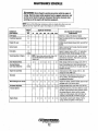
MAINTENANCE SCHEDULE
A WARNING: Never attempt to perform any service while the engine is
running. Wear the proper safety eqnipment such as goggles and gloves, and
use the correct tools fo; each job. Disconnect the battery terminals when
servicing any of the engine's DC electrical equipment.
NOTE: Many of the following maintenance jobs are simple but others are more
difficult and may require the expert knowledge of a service mechanic.
CHECK
EACH
DAY
SCHEDULED
MAINTENANCE
Fuel Supply
HOURS OF OPERATION
50
100
250
500
750 1000 1250
EXPLANATION OF SCHEDULED
MAINTENANCE
Fuel/Water Separator
0
0
Engine Oil Level
0
011 level should indicate between MAX. and LOW on
dipstick.
Coolant Level
0
Check at recovery tank; if empty, check at manifold.
Add coolant if needed.
0
Inspect for proper tension (3/8" to 1/2" deflection)
and adjust if needed. Check belt edges for wear.
Drive Belts
Diesel No.2 rating of 45 cetane or higher.
Check for water and dirt in fuel (drain/replace filter
if necessary).
weekly
Visual Inspection of Engine
Fuel
Fllter~nlel
0
Filler
Starting Batteries
(and House Batteries)
NOTE: Please keep engine surface clean. Dirt
and oil will inhibit the engine's ability to
remain cool
0
0
0
0
0
0
Check for fuel, oil and water leaks. Inspect wiring
and electrical connections. Keep bolts & nuts tight.
Check for loose belt tension.
Initial change at 50 hrs, then change every 250 hrs.
Every 50 operating hours check electrolyte levels
and make sure connections are very tight. Clean off
excessive corrosion.
weekly
Engine Oil (and filler)
0
0
0
0
0
0
0
Initial engine oil & filter change at 50 hrs., then
change both every 100 hours.
Generator
0
0
0
0
0
0
0
Check that AC connections are clean and secure
with no chafing. See GENERATOR SECTION
for additional information.
Heat Exchanger Zinc Anode
0
0
0
0
0
0
0
Inspect zinc anode, replace If needed, clear the heat
exchanger end of zinc anode debris.
0
0
0
0
0
0
0
0
0
Change the filter and/or drain water every 200 hrs.
0
0
0
0
Fuel/Water Separator
Exhaust System
Engine Hoses
0
0
0
Engines & Generators
12
Initial check at 50 hrs., then' every 250 hrs. Inspect
for leaks. Check anti-siphon valve operation. Check .
the exhaust elbow for carbon and/or corrosion
buildup on inside passages; clean and replace as
necessary. Check that all connections are tight.
Hose should be hard & tight. Replace if soft or
spongy. Check and tighten all hose clamps.
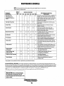
MAINTENANCE SCHEDULE
NOTE: Use the engine hour meter gauge to log your engine hours or record your
engine hours by running time.
CHECK
EACH
DAY
SCHEDULED
MAINTENANCE
Raw Water Pump
.
HOURS OF OPERATION
50
100
250
500
750 1000 1250
0
0
0
0
0
At 750 operating hours,
disassenible and inspect for
overhaul.
Raw Water Pump Drive
Air Inlet Filter
0
0
0
0
'0
Coolant System
Electric Fuel Lift Pump
0
0
0
DC Alternator
0
0
0
0
; -Fuel Injectors
Remove pump and inspect pump shaft and drive
slot for wear.
0
0
Periodically check the wiring connections and
inspect the fuel line connections.
0
Check DC charge from alternator. Check mounting
bracket; tighten electrical connections.
Check and adjust injection opening pressure and
spray condition (see ENGINE ADJUSTMENTS).
0
"
,-Starter Motor
-Preheat Circuit
-Engine Cylinder
Compression
,
Inspect every 100 hours. Remove and clean.
Replace as needed.
Drain, flush, and refill cooling system with
appropriate antifreeze mixture compatible with
various COOling system metals.
0
0
EXPLANATION OF SCHEDULED
MAINTENANCE
Remove the pump cover and impeller. Inspect the
impeller, cam, cover and inner wear plate for wear.
Inspect housing weep holes for signs of shaft water
seal or oil leaks. Check shaft bearings (the shaft
should turn, not wobble).
0
0
Check solenoid and motor for corrosion. Remove
and lubricate. Clean and lubricate the starter motor
pinion drive.
0
0
Check operation of preheat solenoid. Remove and
clean glow plugs; check resistance (0.4-0.6 ohms).
Reinstall with anti seize compound on threads.
0
0
Check compression pressure and timing
(see Engine Adjustments).
-Torque Cylinder Head
Hold-down bolls
0
0
0
At first 50 hours, then every 500 hours
(see ENGINE ADJUSTMENTS).
-Adjustlhe Valve Clearances
0
0
0
Adjust Valve Clearances
(see ENGINE ADJUSTMENTS).
0
Remove, have professionally cleaned and
pressure tested.
-Heat Exchanger
-WESTERBEKE recommends this service be performed by an authorized mechanic.
CAUTION (WESTERLINK or NMEA..20DO): The electronic components in the Digital Diesels draw a very small amount of amperage (milli·amps)!rom the
gelterator:S starting battery when the unit is in a static state, This maybe as much as 50 milli·ampsfor the system ECU and 50 milli-ampsfor each display.
This can be as much as 72 amp·hours in a months time with /10 generator use. It is not necessary to be concerned with this slight amperage draw during
normal seasonal use. However, if the generator set is not to be used for a number of months, such as winter storage, it is best to disconnect the DC power
to the generator with a NMEA·2000 system or shut off the DC·breaker on the generator's control box for a WESTERLINK system.
NOTE: Keep in mind that the Westerbeke generator maybe the DC power supply for the vessel's NMEA·2000 network.
A CAUTION: When servicing/changing
DC components, the DC power must be
turned off using either the DC,breaker or the
battery switch.
/"'fI'ItT/WESTERBEKE
I
Engi~es & Generators
'13
COOLING SYSTEM
DESCRIPTION
Westerbeke marine diesel engines are designed and equipped
for fresh water cooling. Heat produced in the engine by combustion and friction is transferred to fresh water coolant
which circulates throughout the engine. This circulating fresh
water coolant cools the engine block, its internal moving
parts, and the engine oil. The heat is transferred externally
from the fresh water coolant to raw water by means of a heat
exchanger, similar in function to an automotive radiator. Raw
water flows through the tubes of the heat exchanger while
fresh water coolant flows around the tubes; engine heat transferred to the fresh water coolant is conducted through the
tube walls to the raw water which is then pumped into the
exhaust system where finally it is discharged overboard. In
other words, the engine is cooled by fresh water coolant, this
coolant is cooled by raw water, and the raw water carries the
transferred heat overboard through the exhaust syste!Jl. The
fresh water coolant and raw water circttits are independent of
each other. Using only fresh water coolant within the engine
allows the cooling water passages to stay clean and free from
harmful deposits.
FRESH WATER CODLING CIRCUIT
When the engine is started cold, external coolant flow is prevented by the closed thermostat (although some coolant flow
is bypassed around the thermostat to prevent the exhaust
manifold from overheating). As the engine warms up, the
thermostat gradually opens, allowing full flow of the engine's
coolant to flow unrestricted to the external portion of the
cooling system.
Coolant Recovery Tank
A coolant recovery tank aliows for engine coolant expansion
and contraction during engine operation, without any significant loss oJ coolant and without introducing air into the cooling system. This tank should be located at or above the
engine manifold level and should be easily accessible.
CHANGING THE ANTIFREEZE COOLANT
The engine's antifreeze coolant must be changed according
to the ~TENANCE SCHEDULE. If the coolant is .
allowed t6 become contaminated or loose its protection
ability, overheating issues can result as well as external
cylinder erosion and can cause the raw water pump shaft
seals to leak.
NOTE: Refer to the ENGINE COOLANT section for the rec-
A WARNI~: .l1ewai{i of the hot engine coolant.
ommended antifreeze and water mixture to be used as the
fresh water coolant.
Wear protective gloves.
Fresh water coolant is pumped through the engine by a circulating pump, absorbing heat from the engine. Th~ coolant
then passes through the thermostat into the manifold, to the
heat exchanger where it is cooled, and returned to the engine
block via the suction side of the circulating pump.
Drain the engine antifreeze coolant by removing the blo~k
drain plug and opening the drain petcock pIng on the lower
side of the heat exchanger along with removal of the pressure
cap on the water jacketed exhaust manifold. Flush the system
with fresh clean water, then start the refili process.
A CAUTION: Proper cooling system maintenance Is
critical; a.slibstantial number of engine failures can be
traced back fo~ooling system corrosion.
ENGINE BLOCK COOLANT DRAIN
"Mr
WESTERBEKE
Engines & Generators
14
COOLING SYSTEM
Refilling the Coolant
Replacing the Thermostat
After replacing the engine block drain plug, close the heat
exchanger's coolant petcock. Then pour clean, premixed
coolant into the manifold and when the coolant is visable in
Remove the cap screws and disassemble the thermostat housing as shown. When installing the new thennostat and gasket, apply a thin coat of sealant on both sides of the gasket
before p,~ssing it into place. Do not over-tighten the cap
.
-
NOTE: Open the air-bleed petcock on the thermostat housing.
screws . .
Fill the system and watch for antifreeze coolant to flow from
the petcock then close the petcock.
Run the engine and check for normal temperatures and that
there ~e no leaks at the thermostat housing.
Monitor the coolant in the manifold and add as needed. Fill
the manifold to the filler neck and install the manifold pressure cap.
"
Remove the cap on the coolant recovery tank and fill with
coolant mix to halfway between LOW and MAX and replace
the cap. Run the engine and observe the coolant expansion
flow into the recovery tank.
After checking for leaks, stop the engine and allow it to cool.
Coolant should draw back into the cooling system as the
engine cools down. Add coolant to the recovery tank if
needed. Clean up any spilled coolant.
TO
BLEED
PETCOCK
GASKET PN#(1369~i6----
THERMOSTAT
ASSEMBLY
~---COOLANT
TEMPERATURE
SEND OR
PR"".""" CAP
RAW WATER COOLING CIRCUIT
COOLANT RETRACTION
NOTE: Periodically check the condition of the manifold pressure cap. Ensure that the upper and lower rubber seals are in
good condition and check that the vacuum valve opens and
closes tightly. Carry a spare cap.
---
The raw water flow is created by a positive displacement
impeller pump. This pump draws water directly from the raw
water source (ocean, lake, or river) through a hose to the
water strainer. The raw water passes from the strainer
through the raw water pump to' the heat exchanger (through
the heat exchanger tubes) where it cools the engine circulating fresh water coolant. The raw water is then discharged
into the water-injected exhaust elbow, mixing with and cooling the exhaust gasses. This mixture of exhaust gas and raw
water is discharged overboard by the engine's exhaust gas
discharge pressure.
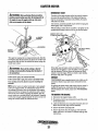
Raw Water Pump
THERMOSTAT
SEALS
A thennos!a!, located near the manifold at the front of the
engine, controls the coolant temperature as the coolant contin-
uously flows through the closed cooling circuit. When the
engine is first started, the closed thermostat prevents coolant
from flowing (some coolant is by-passed through a hole in the
thennostat to prevent the exhaust manifold from overheating).
As the engine warms up, the thermostat gradually opens. The
thermostat is accessible and can be checked, ~leaned, or
replaced easily. Carry a spare thermostat and gasket.
The raw water pump is a self-priming, rotary pump with a
non-ferrous housing and a neoprene impeller. The impeller
has flexible vanes which wipe against a curved earn plate
within the impeller housing, producing the pumping action.
On no account should this pump be run dry as water acts as a
lubricant for the impeller..There should always be a spare
impeller and impeller cover gasket (an impeller kit) aboard.
Raw water pump impeller failures occur when lubricant (raw
water) is not present during engine operation. Such failures
are not warrantable, and operators are cautioned to make sure
raw water flow is present at start-up.
NOTE: Should a failure occur with the pump's internal parts
(seals arid bearings), it may be more cost efficient to purc~ase a new pump and rebuild the original pump as a spare.
En.9ine.E! .& Generators
15
COOLING SYSTEM
NOTE: Also follow the above procedure after having rLln hard
CHANGING THE RAW WATER PUMP IMPELLER
.Close the raw water intake valve. Remove the pump cover
and gasket or O-riug with the aid of two screwdrivers or
pliers. Carefully pry/pull the impeller out of the pump.
Lightly coat the iuside of the pump housing with glycerine.
Install the new impeller and cover with gasket, Open the raw
water intake valve.
aground.·
If the engine temperature gauge ever shows a higher than
nonnal reading, the cause may be that silt, leaves or grass
may have been caught up in the strainer, slowing the flow of
raw water through the cooling system.
RAW WATER STRAINER
RAW WATER PUMP
INSPECTION: CHECK THE BASE OF
EACH BLAOE BY BENDING VIGOROUSLY.
REPLACE THE IMPELLER IF I Htlit Alit
ANY CRACKS.
TYPICAL RAW WATER INTAKE STRAINER
(OWNER INSTALLED)
HEAT EXCHANGER
BLADES WITH
GLYCERINE
A CAUTION: If any of the vanes have broken off the
The heat exchanger is a copper cylinder which encloses a
number of small copper tubes. Raw water is pumped through
the small copper tubes and the fresh water coolant from the
engine is circulated atound the copper tubes. The raw water
removes heat from the fresh water coolant.
impeller, they must be found to prevent blockage in the
cool/ng circuit. They often can be found hl the heat
exchanger.
Raw Water Intake Strainer
HEAT EXCHANGER
NOTE: Always install the strainer at or below the waterline so
the strainer will always be self-priming.
A clean raw water intake strainer is a -vital component of the
HEAT EXCHANGER
engine's cooling system. Include a visual inspection of this
strainer when making your periodic engine check. The water
PETCOCK·
in the glass should be clear.
Perfonn the following maintenance after every 100 hours of
CLEAN
DEBRIS
operation:
1. Close the raw water seacock.
CLEANOUT
DEBRIBAT
BOTHENOB
2. . Remove and clean the strainer filter.
3. Clean the glass.
4. Replace the washer if necessary.
5. ReaSsemble and install the strainer.
6. Open the seacock.
7. Run the engine and check for leaks.
ANODE
HEAT EXCHANGERS ARE
N..&PAVAILABLE WITH
CUPRO·NlCKEL TUBING
Enl!ines & Generators
16
COOLING SYSTEM
Zinc Anode·
,
If the zinc anodes need replacement, hold the hex boss into
.. which the zinc anode is threaded with a wrench while loosening the anode with another wrench. This prevents the hex
boss from possibly tearing off the exchanger shell. After
removing the Zinc, note the condition of it. If the zinc is in
poor condition, there are probably a lot of zinc flakes within
the exchanger. Remove the end of the heat exchanger and
clean the inside of all zinc debris. Always have a spare heat
exchanger end gasket in case the present one becomes damaged when removing the end cover. Replace the gasket (refer
to your engine model's heat exchanger end gasket part number), O-ring and cover, and install a new zinc anode.
/
A zinc anode, or pencil, is located in the raw water cooiing
circuit within the heat exchanger. The pmpose of having the
zinc anode is to sacrifice them to electrolysis action taking
place in the raw water cooling circuit, thereby reducing the
effects of electrolysis on other components of the system.
The condition of the zinc anode should be checked monthly
and the anode cleaned or replaced as required. Spare anodes
should be carried on board.
NOTE: The threads of the zinc anodes are pipe threads and
do .not require sealant. Sealant should not be used as it may
insulate the zinc from the metal of the heat exchanger housing preventing electrolysis action on the zinc.
Heat Exchanger Service
NEW
REPLACE
REPLACE
After approximately 1000 hours of operation, remove, clean
and pressure test the engine's heat exchanger. (Aloca! automotive radiator shop should be able to clean and test the heat
exchanger.)
CLEAN AND
REUSE
ZINC ANODES
NOTE: Operating in silty and/or tropical waters may require
that a heat exchanger cleaning be peifonned more often than
every 1DOlt hour•.
NOTE: Electrolysis action is the result of each particular
installation and vessel location; not that of the engine.
DESCRIPTION
AIR INTAKE I SILENCER
NOTE: Regular air filter cartridge maintenance is essential
for proper engine operation. Failure to maintain the air filter
cartridge will result in air obstruction into the engine, causing
poor fuel combustion and resulting in smokey/sooty exhaust
discharge a!ong with lube oil consumption and possible filter
deterioration which could result in internal engine damage.
A marine diesel engine ronning at 1800 rpm will typically
consume as much as 6,000 cubic feet of air per hour. Not
only most the engine room be well ventilated, the air flow
into the engine must be unrestricted.
AIR INTAKE FILTER/SILENCER
The replaceable canister contains a paper element that should
be inspected every 100 operating hours. Dut in the element'
~an be shaken off or cleaned with compressed air, however,
If the element is greasy or black with dirt, the canister must
be replaced, cany a spare.
. .. .
FILTER CARTRIDGE
#03970
NOTE: To operate efficiently a diesel engine must intllke a
continuous volume of clear ail; Hard starting, an erratic idle,
and black exhaust smoke are all symptoms of a restricted air
intake.
TURN OVER WHEN INSTALLING
FILTER CARTRIDGE INSTALLATION
Detach the air inlet hose from the air intake. Unplug the aii:
temperature sensor from the engine harness. Then remove the
bolts that secure the air intiiKe silencer housing to the inlet base .
and remove the housing, screen facing out. Reinstall the
housing to the inlet base. Plug in the air· temperature sensor to
the harness and reconnect the air inlet hose.
17'
FUEL SYSTEM
DIESEL FUEL
FUEL FILTERS
Use No.2 diesel fuel with a cetane rating of 45 or higher. Do
not use kerosene or home heating fuel
The fuel injection pump and the fuel injectors are precisely
manufactured and they must receive clean diesel fueL free
from water and dirt. To ensure this flow of clean fuel; the fuel
must pass thruugh at least two fuel filters, a fuel filter/water
separator and the engine's spin-on fuel filter. Visually inspec~
clean, and change these filters according to the maintenance
schedule in this manual.
FUEL WATER SEPARATOR
A primary fuel filter of the water separating type must be
installed between the fuel tank and the engine to remove
water and other contantinant's from the fuel before they can
be carried to the fuel system on the engine.
Most installers include a filter/water separator with the
installation package as they are aware of the problems that
. contantinant's in the fuel can cause.
A typical fuel filter/water separator is illustrated below.This
is the Rayeor Model 500 MA. Keep in mind that if a water
separator type filter is not installed between the fuel supply
tank and engine-mounted fuel system, any water in the fuel
will affect the fuel pump, engine filter, and injection equipment. The owner/operator is responsible for making certain
the fuel reaching the engine's injection equipment is free of
impurities. This process is accomplished by installing and
maintaining a
system.
FUEL LIFT PUMP FILTER
To ensure clean fuel into the fuel lift pump, there is a small
in-line fuel filter connected to the fuel lift pump elbow. This
filter shonld·be replaced every 200 hours of operation.
FUEL FILTER
WATER SEPERATOR
The fuel inject\on pump is the most important component of
the diesel engine,requiring the utmost caution in handling. The
fuel injection pump has been thorougbly bench-tested and the
owner-operator is cautioned not to attempt to service it. If it
requires servicing, remove it and take it to an authorized fuel
injection pump service facility. Do not attempt to disassemble
and repairit.
Speed (hertz) and timing are the only adjustments the
servicing dealer can perform on the injection pump. Other
types of adjustments or repairs must be performed by a
qualified injection service shop.
FUEL LIFT PUMP
Periodically check the fuel connections to and out of the
pump and make sure that no leakage is present and that the
fittings are tight and secure. The DC grouud connection at
one of the pumps mounting bolts should be clean and well
secured by the mounting bolt to ensure proper pump
operations.
When energized thru the preheat circuit, the fuel lift pump
will purge air from the fuel system and provide continuous
flow of fuel as the engine is running.
FUEL FILTER ASSEMBLY
ENGINE FUEL FILTER
Periodlcally check the fuel connections and the bowl for
leakage. Clean the filter element with kerosene or diesel fuel
after the first 50 hours then follow the MAINTENANCE
SCHEDULE for cleaning and replacement.
Changing/cleaning the filter element
1. Shut off the fuel supply.
2. Unscrew the retainer ring that holds the filter bowl to the
housing and allow the bowl to come away from the
housing,
3. Remove and replace the filter element and clean the bowl.
4. Replace the sealing "0" ring and reassemble the bOWl to
the housing. Thread tile retainer ring on carefully so as not
to cross thread. When retainer contacts the "0" ring.
tighten 1/4 - 1/2 turns by hand. Open the fuel supply and
run the engine to inspect for leaks.
Engines & Generators
18
ENGINE LUBRICATING OIL
LUBRICATION DIAGRAM
2. Repkzcing the Oil Filter. When removing the used oil filter, you may find it helpful and cleaner to punch a hole in
the upper and lower portion of the old filter to drain the
oil from it into a container before removing it This helps
to lessen spillage. A small automotive filter wrench
shouldbe helpful in removing the old oil filter:
NOTE: Do not punch this hole without jirst loosening the
jilter to make certain it can be removed.
Place some paper towels and a plastic bag around the filter when unscrewing it to catch any oil left in the filter.
(Oil or any other fluid on the engine reduces the engine's
cooling ability. Keep your engine clean.) Inspect the old
oil filter as it is removed to make sure that the rubber
sealing gasket comes off with the old oil filter. If this rubber sealing gasket remains sealed against the filter
bracket, gently remove it.
OIL PRESSURE
OIL PRESSURE -->o-::rnlll-'~
SWITCH
OIL PRES:SURI:----'
RELIEF VALVE
OIL
OIL DRlllli-----"
. OIL SCREEN
ENGINE OIL CHANGE
1. Draining the Oil Sump. Discharge the used oil through
the sump drain hose (attached to the front of the engine)
while the engine is warm. Drain the used oil completely,
replace the hose in its bracket, and replace the end cap
securely.
ROTE: Thread size for the lube oil drain .hose capped end
is II4NPT.
SEALING
APPLY CLEAN ENGINE OIL
WHEN INSTALLING
BMM
SPIN ON
TURN ON HAND TIGHT
11/16 INCH
SOCKET
When installing the new oil filter element, wipe the filter
gasket'.s sealing surface on the bracket free of oil and
apply a thin coat of clean engine oil to the rubber gasket
on the new oil filter. Screw the filter onto the threaded oil
filter nipple on the oil filter bracket, and then tighten the
filter firmly by hand.
NOTE: Generic jilters are not recommended, as the lnaterial standards or diameters a/important items on generic
parts might be entirely different from genuine parts.
Immediately after an oil jilter change and oil jill, run the
DRAIN HOSE
engine to make sure the oil pressure is normal and that
Always observe the used oil as it is removed. A
yellow/gray emulsion indicates the presence of water in
the oil. Although tbis condition is rare, it does require
prompt attention to prevent serious damage. Call a qualified mechanic should water be present in the oil. Raw
water present in the oil can be the result of a fault in the
exhaust system attached to the engine andlor a siphoning
of raw water through the raw water cooling circuit into
the exhaust, filling the engine. This problem is often
caused by the absence of an anti~siphon valve, its poor
location or lack of maintenance.
~
there are no oil leaks around the (lew oil jilter.
3. Filling the Oil Sump. Add new oil through the oil filler
cap on the top of the engine or through the side oil fill.
After refilling, run the engine for a few moments wbile
checking the oil pressure. Make sure there is no leakage
around the new oil filter or from the oil drain system, and
stop the engine. Then check the quantity of oil with the
lube oil dipstick. Fill to, but not over the high mark on
the dipstick, should the engine require additional oil.
WESTERBEKE
Engines & Generators
19
OIL PRESSURE
ENGINE BLOCK
DESCRIPTION
The lubricating system is a pressure feeding system using
an oil pump. The engine oil is drawn from the oil sump by
the oil pump, which drives the oil, under pressure, through
the oil filter, oil cooler and various lubricating points in the
engine. The oil then returns to the oil sump to repeat the
continuous cycle. When the oil pressure exceeds the specified pressure, the oil pushes open the relief valve in the oil
pump and returns to the oil sump, keeping the oil pressure
within its specified range.
TESTING OIL PRESSURE
lOlL PRESSURE
'MANIFOLD
OIL PRESSURE
The engine's oil pressure, during operation, is indicated'
\
by the oil pressure gauge on the instrument panel. During
normal operation, the oil pressure will range between 40 and
60 psi (2.8 and 4.2 kg/cm').
QILPRESSUilE ..
35.0 Ib/in' (3.8 KQ/cm') or more al1800 rpm.
NOTE: A newly started, cold enginli'9,on· have an 'oil pressure
reading up to 60 psi (4.2 kg/cm'). A warmed engine can have
an oil pressure reading as low as 35 psi (2.5 kgfcm'). These
readings will vary depending upon the temperature ofthe
engine and the rpm<.
LOW OIL PRESSURE
OIL PRESSURE SENSOR
The specified safe minimum oil pressure is 4.3 + 1.4 psi (0.3
+ 0.1 kg/em'). A gradual loss of oil pressure usually. indicates
a wombearings. For additional information on low oil pressure readings, see the ENGINE TROUBLESHOOTING chart.
An oil pressure sensor is mounted on the oil manifold for the
engine. It sends a voltage signal to the ECU that is interpreted
as pressure. Should this signal fall below a set point in the
ECu. The ECU will open the K2 run relay shutting the unit
down. It will then display the fault on the LCD Display
screen. Engine oil pressure dropping 10 - 15 psi will cause
this to occur.
OIL PRESSURE RELIEF VALVE
An oil pressure relief valve is located on the engine block
just below the injection pump. This valve opens at
appoximately 50 psi [343 kpa] and maintains that pressure.
NOTE: To test the oil pressure, install a mechanical pressure
gauge as shown. Warm up the engine and read the oil pressure gauge. Oil Pressure should be 35.0 lb/in' (3.8 Kg/cm')
or more at 1800 rpm.
LOCATED JUST
UNDER THE
FUEL INJECTION
PUMP ON THE
ENGINE BLOCK.
-...v- WESTERBEKE
Engines _& Generators
20
REMOTE OIL FILTER (OPTIONAL)
PN:040078HEMOTEOILFILTER SET
INSTALLATION
.
To instal!, simply remove the engine oil filter and thread on
WES1ERBEKE'S remote oil filter kit as shown. Always
install this kit with the oil filter facing down a. illustrated.
This popular accessory is used to reloc~te the engine's oil filter from the engine to a more convenient location such' as an
engine room bulkhead.
Contact your WES1ERBEKE dealer for more information.
NOTE: Westerbeke is not responsible for engine failure due to
incorrect installation of the Remote Oil Filter.
NOTE: Refer to ENGINE OIL CHANGE in this fI11lnual for
instructions on removing the oil jilter.
A CAUTION: It Is vital to Install the oil lines
correctly. If the oil flows in the reverse direction, the
by·pass valve In the filter assembly will prevent the oil
from reaching the engine causing an internal engine
failure. If there is no oil pressure reading, shutdown
immedialety and check the hose connections
APPLY ATHIN COAT OF CLEAN OIL TO THE O-RING WHEN
INSTALLING THIS KIT. THREAD THE KIT ON, THEN HAND
TIGHTEN AN ADDITIONAL 3/4 TURN AFTER THE O-RING
CONTACTS THE BASE.
NOTE THE "IN" AND "OUT" MARKINGS
ON THE ADAPTER WHEN THE HOSES ARE
REMOVED FOR INSTALLATION SO THEY
• WILL BE RECONNECTED CORRECTLY.
IN CONNECTION HOSE
MUST ATTACH TO THE OUT .
CONNECTION AT THE
REMOTE OIL FILTER.
APPLY ATHIN COAT OF CLEAN OIL TO THE FILTER GASKET WHEN INSTALLING. AFTER THE
FILTER CONTACTS THE BASE, TIGHTEN IT AN
ADDITIONAL 3/4 TURN.
Englnes..~, ~en~,:ators
21
ENGINE TROUBLESHOOTINO-
LCD DISPLAY FAULTS ~
. Note: The engines DC electrical system is protected by a 20 amp
rocker type reset circuit breaker mounted on the control paneL·
--
..
-
.. _-- .... __ .. -
_.
Problem
START BUTTON depressed, no panel
Indications.
START BUTTON depressed, no starter
engagement.
START BUTTON depressed; panel
indications OK; starter solenoid OK
fuel solenoid not functioning.
Generator engine cranks, but does not
start, fuel solenoid energized.
Note: there is a 8 - 10' sec. crank cycle.
;If the engine does not start. The cycle ~
will-terminate and a Underspeed fault ,
will display on the LCD display screen.
Battery runs down.
Battery not charging
Probable Cause
Verilicalion/Remedy
-
.- .
1. Battery'Switch noton.
1. Check !:\witch and/or battery connections.
2. Circuit breaker trippedioff:'
2. Reset breaker; if breaker trips again, check preheat solenoid
circuit and check circuit for shorts to ground.
3, Loose b~ttery connectiQns.
4. Check (+) connection to starter solenoid and (-) connection to
engine ground stud. Check battery cable connections.
1. Connection to solenoid "faulty.
1. Check connection.
2. Faulty solenoid.
2, Check that 12 volts are present at the solenoid connection.
3. Loose battery connections.
3. Check battery connections.
4. Low battery.
5. Kl relay.
4. Check battery charge state.
1. Poor connections to fuel solenoid.
5. Check Kl relay.
1. Check connections.
'2. . Defective fuel solenoid.
2. Check that 12 volts are present at the (+) connection on the
fuel run solenoid.
1. Faulty fueling system.
1. Cileck that fuel valves are open.
la. Switch to combine house and start batteries.
lb, Replace batteries.
lc. Check fuel lift pump.
ld, Change inlet fuel filter.
2. Preheat solenoid faulty.
2. Check solenoid.
1. High resistance leak to ground.
1, Check wiring. Insert sensitive (0 - .25 amp) meter in battery
lines. Do not start engine. R~move connections and replace
after short Is located.
2. Low resistance leak.
2. Check ali wires for temperature rise to locate the faul!.
3. Poor battery connections.
3. Check table connections at battery for loose connections,
corrosion.
4. DC alternator not charging.
4. Check connections, check belt tension. test alternator. See.
DC ELECTRICAL SYSTEM/ALTERNATOR.
1, Pertorm D.C. voltage check of generator charging circui!. See
DC ELECTRICAL SYSTEM/ALTERNATOR.in this manual.
2, Check drive belt tension. Alternator should turn freely. Check
for loose connections. Check output voltmeter, Ensure 12 volts
are present at the Exc. terminal.
1. DC charge circuit faulty.
2. Alternator drive.
Generator engine stops.
(Fault display under speed)
NOTE: The engines DC electrical system
is protected by a 20 amp rocker type
reset circuit breaker on the lront of the
control panel.
(continued)
1. Switches and/or wiring loose
or disconnected.
1. Inspect wiring for short circuits and loose connections.
Inspect switches for proper operation.
2. Fuel staruation.
2, Check fuel supply, fuel valves, fuel feed strainer.
3. 20 Amp circuit breaker tripping.
(LCD display blank)
3. Check for high OC amperage draw during operation.
Ensure breaker is not overly sensitive to heat which would
cause tripping.
4. Exhaust system is restricted.
5. Water in fuel.
4. Check for blockage or collapsed muffler.
6. Air intake obstruction.
5. Pump water from fuel tank(s); change filters and
bleed fuel system.
6. Check air intake filter cartridge.
Engine starts, runs and shuts down.
1. Faulty oil pressure switch.
1. Check oil pressure switch.
Exhaust smoking problems
2. Water temperature switch.
1. Blue smoke.
2. Check water temperature switch.
1. Incorrect grade of engine all.
la. Crankcase is overfilled with engine oil (oil is blowing out
through the eXhaust).
2. Engine is running cold.
2a. Faulty injector or Incorrect Injector timing.
3. Improper grade of fuel or possible generator overload.
3a. Fuel.burn incomplete due to high back pressure in exhaust or
Insufficient air for proper combustion (Check for restrictions ih
exhaust system: check air intake).
3b. Improperly timed injectors or valves or poor compression.
,
2. White smoke.
3. Black smoke.
l"'fIY'IWESTERBEKE
I, Engines & Generators
22
3&. Lack of air - check air intake and air filter. Check for proper
ventilation.
Y'
ENGINE TROUBLESHOOTING
LCD DISPLAY FAULTS
PROBLEM
LCD DISPLAY DOES
NOT ILLUMINATE
LOW OIL PRESSURE
HIGH COOLANT TEMPERATURE
HIGH EXHAUST TEMPERATURE
BATTERY VOLTAGE
GENERATOR FREQUENCY
Overspeed (steady LED)
Underspeed (flashing LED)
LED OISPLAY EDGES
TURN PINK
WAITING FOR ECU
PROBABLE CAUSE
1.
2.
3.
4.
VERIFICATIONJREMEDY
Check battery.
20 amp breaker off.
Loose display connection.
1 amp fuse blown (faulty).
1.
2.
3.
4.
Battery on.
Turn breaker on.
Check all cable connections.
Check/replace. Determine cause
1. Oil level low/oil leak.
1. Check oil level, add oil and repair leaks.
2. Lack of oil pressure
3. Ground connection.
2. Test oil pressure. If OK, test oil pressure sendor, inspect
oil filter, inspect oil pump.
3. Check ground connection.
4. Faulty control module (ECU).
4. Inspect all the plug connections/replace.
5.
1.
2.
3.
4.
5.
6.
5. Check sensor/replace.
1. Add coolant. Check for leaks. ,
2. Inspect impeller/pump/replace,
3. Adjust belt tenSion, replace belt.
4. Check sensor/replace.
5. Check ground circuit.
6. Check plug connections/replace.
Faulty oil pressure sensor.
Check system coolant level.
Sea water pump,
Check water pump drive belt.
Faulty temperature sensor.
Ground connection.
Faulty control module (ECU).
1. Check sea water flow.
1. Inspect thru hull fitting, hose and strainer. Correct
as needed.
2.
3.
4.
5.
6.
1.
2.
3.
4.
1.
2.
3.
4.
2.
3.
4.
5.
6.
1.
2.
3.
4.
1.
2.
3.
4.
1.
2.
3.
4.
5.
1. Ventilate compartment.
Note: Heat will often change the color of an LCD
display. This will not effect the operation of the engine.
1. Check compatibility with Westerlink or NMEA.
2. Check all cable connections.
3. Turn ON, check DC voltage across breaker.
4. CheCk/replace fuse. Check DC voltage across fuse holder
5. Check all terminating resistors are in place. 120 ohm
per resister me'asured across pin #4 and #5.
6. Check between pins P2-24 and P2-25. P2 ECU plug
unplugged from ECU. Power turned ON. If voltage is
present, ECU is faulty.
Faulty exhaust temperature switch.
Gmund Connection.
Faulty control module (ECU).
Sea water pump.
Faulty fire suppression system.
Check alternator drive belt.
Check charge Voltage.
Check battery connections.
Faulty control module (ECU).
Check engine speed.
Check fuel supply.
Amperage load.
Crank cycle with no start.
(underspeed fault)
1. Compartment ambient temperature
too high.
ECU and LCD display not compatible
Loose cable connection.
Panel DC breaker OFF.
Blown 8 amp fuse.
Terminating Resistors.
6. Battery Voltage to ECU.,
-..v'
TesVrepl~ce.
Check ground circuit.
Check plug connections.
Inspect impeller/replace.
By-pass system/check.
Adjust tension/replace if worn.
Check excitation. Replace/repair alternator
Check + and - cables from battery to engine.
Check plug connections/replace.
Check speed setting.
Inspect filters/replace filters. Test fuel pump operation,
Check + and - cables from battery to engine.
Check cause for no start.
WESTERBEKE
Engines & Generators
23
ENGINE ADJUSTMENTS
DRIVE BELT ADJUSTMENT
ELECTRONIC GOVERNOR
Proper inspection, service and maintenance of the dtive belts
is important for the efficient operation of your engine (see
Drive Belts under MAINTENANCE SCHEDULE).
Drive belts must be properly tensioned. Loosedtive belts will
not provide proper alternator charging and will eventually
damage the alternator. Drive belts that are too tight will pull
the alternator out of alignment and/or cause the alternator to
wear out prematurely. Excessive dtive belt tension can also
cause rapid wear of the belt and reduce the service life of the
fresh water pumps bearing. A slack belt or the presence of oil
on the belt can cause belt slipping, resulting in high operating
temperatures.
The dtive belt is properly adjusted if the belt can be deflected
no less than 3/8 inch (10mm) and no more than 112 inch
(12mm) as the belt is depressed with the thumb at the midpoint between the two pulleys on the longest span of the belt.
A spare belt or belts should always be carried on board.
The Electronic Governor regulates the engine speed by
sensing the engine's RPM with a magnetic pick-up at the
flywheel. The governor's controller continuously monitors
the engines speed and if there is any discrepancy, the
controller signals the actuator and the actuator adjusts the
engine to the desired speed electronically.
A
WARNING: Never attempt to check or adjust the
drive belt's tension while the engine Is in operation.
Adjusting Belt Tension
1. Loosen the alternator adjusting strap bolt and the base
mounting bolt.
2. Wilh Ihe belt loose, inspect for wear, cracks and frayed
edges.
3. Pivot the alternator on Ihe base mounting bolt to the left
or right as required, to loosen or tighten.
4. Tighten tlle base mounting bolt and the adjusting strap
bolt.
5. Run the engine for about 5 minutes, then shut down and
recheck Ihe belt tensions.
Actuator
The following instructions are for adjusting or replacing
the actuator.
1.' Shut-off the DC power to the generator.
2. Disconnect the actuator wires from Ihe wiring harness.
3. Measure the distance between the actuator and the engine
mounting surface as shown.
Inmrrl---l ENGINE MOUNTING
ACTUATOR
SURFACE
-1tJWIlIIw.r~~
-JAM NUT
-.J)......___
MEASURE FOR
REFERENCE
4. Back-off the 1 7/16" jam nut and unscrew the actuator.
5. Apply a small amount of teflon sealant to the replacement
actuator and screw the actuator into the engine's
mounting boss. Maintain the same distance between the
actuator and the engine mounting sUlface as previously
measured Secnre the actuator's position with the jamuut.
(The standard distance is 13116" to 7/8").
6. Reconnect
the actuator wires and test the unit.
,
f+-----13/16" TO .7/8"
STANDARD
NOTE: lithe unit does not
shut down properly when
testing"loosen the jam nut
and turn the actuator in
/
~
WESTERBEKE
Engines & Generators
24
1/8-114 of a tum unlil proper
shutdown is· achieved.
ENGINE ADJUSTMENTS
NOTE: WESTERBEKE recommends that the following engine adjustments be peiformed by a competent engine mechanic. The informaiion
below is provided to assist the· mechanic:
VALVE CLEARANCE ADJUSTMENT
Make the following adjustments when the engine is cold.
1. Remove the cylinder head cover.
2. Slightly loosen the cylinder head bolts, and retighten them
to the specified torque in the number sequence shown
below. Tightening TDrque 55:!: 4lb·n (BB±"S'Nm)
010
04
Os
06
(M
05
01
012
(b) With No.1 piston at top dead center on th~compression
stroke; the rocker lU1IlS
not be moved When the
crankshaft is turned approximately 20' in both directions.
(c) I{therockerarmsmove,No.l piston is at top dead
cehteron the iniake or exhauststroke, In such a case,
, turri the crankShaft 360' in the direction of ~ngine '.
rotation again. N~.l piston is now at top dead center on
thetompn;ssion stroke.'
will
03
'011
FOUR CYLINDER
FRONT
4.' Loosen the lock nut for the adjusting ·screW. With a fe~ler
ga).lge inserteq b,etweentherocker ann and valve cap,
adjust the valve clearance by turning the adjusting screw.
THREE CYLINDER
3:',Find top dead center compression position for No.1
piston by using the procedure that follows:
(a) Thmthe crankshaft until IDC mark on the crankshaft
pulley is aligned with the mark on the timing gear case.
TDC (TOP DEAD CENTER)
MARK FOR
1
AND NO.4
.
{"''';,
~
n'
O.25mm,
.
~" ,'"
(O.,009BINCHES)
. ::., ~;! - INTAKE & EXHAUST
I ' . . .'1~~
. :":1
-- ~.,
.
, >
S. After tbe valve clearance on the valves for No.1 cylinder
, bave, been adjuste!!. Follow the firing order seq~ence
below for eit\lerthe t\lIee OI four cylil!derl!\odel. Ro/jlte
tbecraDksh/lft iI!, the directiol! of l!orinalIQtatiOI! and
adjus(the valves fQr'th~next cylindel il1tbe firing order.
Repeat nntil aIr cylinder valves are adjnsted.
FlRlNG,QR!)ER
Three Cylhidetl- 3 - 2
240 degrees of crank shaft rotation
Four cYIlndeI 1 ~ 3 - 4-2 180 degrees of crank sjlaft rotation
6.
After allyalves bave l1e,n adjusted,turn the crook shaft two to
tnre;e. cOfflplew'revolutions and recheck valve 'Clearances' followi'ng
steps #3. - #5.
TDC MARK
'NO.2 AND NO.3 PISTONS
7.. Install the rocker cover.
ROCKERCOVER BOLT TORQUE: 2 - 3 It-Ib (0.3 - 0.45 m-kg)
1;-'1.f!irre~ ,~J~e.~erator$
2'5
ENGINE ADJUSTMENTS
NOTE: WESTERBEKE recommends that the following engine adjustments be performed by a competent engine mechanic. The [n/ormation
below is provided to assist the mechanic.
TESTING ENGINE COMPRESSION
FUEL INJECTORS
Make certain the oil level (dipstick) is at the correct level and
the air intake filter is clean. The battery and starter motor
must also be in good condition.
1. Warm the engine to normal operating temperature.
2. Move the control lever to a position for shutting off the
fuel. (Disconnect the wires if a fuel shutdown solenoid is
used).
3. Remove all the glow plugs from the engine and install
the compression gauge/adapter combination to tbe cylinder on which the compression is to be measured.
In case of severe vibrations and detonation noise, have the
injectors checked and overhauled by an authorized fuel
injection service center. Poor fuel quality, contaminants and
loss of positive fuel pressure to the injection pump can result
in injector faults. Since fuel injectors must be serviced in a
clean room enviroment, it is best to carry at least one extra
injector as a spare should a problem oCCur.
Before removing the old injector, clean the area around the
base of the injector to help prevent any r)lst or debris from
falling down into the injector hole. If the injector will not lift
out easily and is held in by carbon build-up or the like, work
the injector side-to-side with the aid of the socket wrench to
free it, and then lift it out.
The injector seats in the cylinder head on a copper sealing
washer. This washer should be removed with the injector and
replaced with a new washer when the new injector is
installed.
Injeclor to Cylinder Head Tightening Torque 40 ± 4 ft-Ib (5.5 ± 0.5 kgf-m)
TESTING ENGINE
COMPRESSION
PRESSURE
GAUGE
FUEL INJECTOR
4. Close the raw water seacock (thru-hull).
5. Crank the engine and allow the gauge to reach a
maximum reading, then record that reading.
6. Repeat this process for each cylinder.
Compression pressure 427 psi (30 kgf/cm2) af 290 rpm.
Maximum permissible difference between cylinders is 42.7 psi
(3 kgf/cm2)
NOTE: If the readings are below the limit, the engine needs
repair
7. Re-install the glow plugs (use anti-seize compound on
the threads) and reset the fuel shut-off to the run position.
8. Open the raw water seacock (thru-hull).
LOW COMPRESSION
When low coinpression is found, detennine the cause by
applying a small amount of oil in the cylinder thru the glow
plug hole. Allow the oil to settle.
Install the pressure gauge and repeat the above test. If the
compression reading rises dramatically, the fault is with the
rings.
If the compression valve does not rise, the problem is with
the valves.
A slight rise in compression would indicate a problem with
both the rings and the valves.
~
WESTERBEKE
~1?1J9~fJ~~_&. Generators
26
FUEL INJECTORS
REMOVING THE INJECTORS
Inspecting Spray Pattern
NOTE: Injector must be serviced in a "clean room" environment.
1, Operate the hand lever of the nozzle tester at intervals of
one stroke per second to check if the fuel is injected correctly in its axial direction. A nozzle is defective if it
injects fuel in an oblique direction or in several separate
strips. Also, a spray in the form of particles indicates a
defect. These defects may sometimes be caused by clogging with dust and, therefore, all parts should be carefully
cleaned before reassembly. (Care should'be taken not to
expose ones skin to this spray as it may penetrate the skin
and cause infection.)
1. Disconnect the high pressure lines from the injectors and
loosen the lines at their attachment to the injection pump
and move them out of the way of the injectors. Avoid
bending the lines.
2. Using a 17mm long socket, remove the fuel retum line in
its entirety from the top of the injectors. Take care not to
lose the two sealing washers and banjo bolt that attaches
the fuel return line to each injector.
~
NOTE: Clean the area around the base of the injector
prior to lifting it out of the cylinder head to help prevent
any rust or debris from falling down into the injector
hole. If the injector will not lift out easily and is held in
by carbon build up or the like, work the injector side to
side with the aid of the J7mm deep socket wrench to free
it and then lift it out.
3.
.
'"i NORMAL
I
'11 111
lull'
ml;\
The injector seats in the cylinder head on a copper sealing washer. This washer should be removed with the
injector and replaced with a new washer when the injector is reinstalled.
INJECTION TESTING
tion starting pressure of nozzle and, if it exceeds the
limit, adjust or replace the nozzle. When using nozzle
tester, take the following precautions:
replace it. At the same time, clean or replace the filter.
Set the nozzle tester in a clean place where there is no
dust or dirt.
Mount the nozzle and nozzle holder on·the nozzle
tester.
Use the fuel at the approximate temperature
of 68' F (20' C)
Operate the hand lever of nozzle tester several times to
bleed the air in the nozzle line, then move the hand
lever at intervals of one stroke per.second while reading the injection starting pressure.
I.
','I"
,.
'"
I~"
CHATTERING TEST
~i"1
! SHIM THICKNESS
~
ADJUSTING
SHIM
INJECTION PRESSURE
1920 PSI
"'IIY'
~\ ,FAULTY
The injection starting pressure for the injectors is adjusted by
increasing or decreasing the thickness of the adjusting shim.
The shim has 10 different thicknesses for every 0.0020 in
(0.05 mm)~ between 0.0049in (1.25mm).to 0.0669in (1.7mm)
With each 0.0020in (0.05mm) increase, injection pressure is
increased approximately 71.1lb/in' (5.0 kg/em'). When
replacing the shim, grip the retaining nut in a vise and
remove the body with a wrench. Tighten the retruning nut to
the specified torque:
a. If the diesel fuel of the nozzle tester is discolored,
e.
'~I FAULTY
,~.\',
..,
DRIP TEST
of such velocity that it may ppnetrate deeply into the
skin of fingers and hands, destroying tissue. If it
enters the bloodstream, it may cause blood poisoning.
d.
~:,
I~;
[I
A CAUTION: The spray injected from the nozzle is
c.
U]J]I
2. Apply the pressure of 1635 lb/in' (115 kg/em') to nozzle
by operating the hand lever, and check the drips from the
nozzle tip. If it drips or has a large accumulation 'of fuel
on the bottom, it is considered defective and should be
repl~ced. A very small amount of fuel may sometimes
remain on the tip of the nozzle; however, this does not
indicate a defect.
1. Using the nozzle tester, check the spray pattern and injec-
b.
l1IJ
WESTERBEKE
Engines & .Generators
27
i
FUEL INJECTION TIMING
PREPARATION
ADJUSTMENT
a. If the fuel injection timing is incorrect, change the
thickness of shims under the fuel injection pump. An
increase or decrease of the shims by O.1mm (0.004 in)
.
will vary the timing by 10.
h. Increase the thickness of the shims to retard the timing
or decrease it to advance the timing.
a. Close the fuel shut-off valve.
h. Disconnect the No.1 fuel injection pipe from the
cylinder head and injection pump.
c. Remove No.1 delivery valve holder from the injection
pump. Remove the delivery valve and spring from the
holder. Restore the delivery valve holder only to the
injection pump.
d.Connect the fuel injection pipe to the injection pump.
e. Hold the speed control lever in the low speed position.
(Generator) remove the fuel shut-off solenoid.
ADJUSTMENT RANGE:
Four kinds of shims are available in thicknesses
0.2mm (0.0079 in), 0.3mm (0.0118 in), O.4mm
(0.0157 in) and 0.8mm (0.0315 in). These shims have
no identification, measure the thickness of each shim
with calipers before using it.
INSPECTION [Fuel Flow Method]
a. Open the fuel shut-off valve. Turn the hey switch to the
ON position and press preheat.
NOTE: Fuel will come from the injection pipe with high
pressure when the starter switch key is turned to ON position
if the engine is equipped with an electric fuel pump. Direct
fuel flow into the container.
h. Slowly tum the crankshaft clockwise, looking at the
open end of the injection pipe. The instant fuel stops
coming out is the fuel injection timing.
NOTE: Tum the crankshaft in reverse direction.iust a little and
do step b again to verify the injection timing.
c. The fuel injection timing is correct if the IT mark on the
crankshaft pulley is aligned with the mark on the timing
gear case when fuel stops from the injection pipe.
FUEL INJECTION TIMING:
~ ~ ::FJ~
.",.,
X. t!">
.
.--....I..h>...,IJj
(?) ---
'"
fo~:-r-> - . .
1
~~.{i'i:
~~
rtt.,,,
»~.:::: @Q~"" /
I
A CAUTION: Apply sealant to both faces of each
shim to prevent oil leaks.
c. After the timing has been adjusted, make sure it is
correct.
d.Close the fuel filter valve and restore the delivery valve
and injection pipe to the original state.
TDC MARK
17' 19'
,f
20'
"""~~:":23'
BlDC 17' (STANDARD)
~I
~~,
T'l-I~\...-;.;\
STANDARD ± 1.50
,,-,
2,0
~~
~
4~U
D_.1"l
FUELFLOWS
t I·~'
~'f1c...'='/'I-I p...
~
~
r- 1l~1~
/'?-..~
1:::S<f
rAA
\
-N
4l:I;::~""r',1ft' 0< '
FUEL
S:~S
"" •
k!...
r••~
'~.,,£;
.mG5
1<
ANGLE BY WHICH FUEL.
INJECTION TIMING
0
.
ANGLE BY WHICH FUEL
INJECTION TIMING
IS ADVANCED
/1~ ~ ~. 'f\
/'
(/1
•
AlTERNATE METHOD
In the fuel flowinethod, the delivery valve has to be removed.
As a result, there is a good chance for dirt particles to get
.inside the fuel injection pump. In this alternate method,
however, it is not necessary to remove the delivery valve.
a. Disconnect No.1 fuel injection pipe at the fuel
injection nozzle (cylinder head).
b. Prime the fuel system.
c. Slowly tum the crankshaft clockwise nntil fuel just
swells at the free end of the injection pipe and, at that
instan~ check the position of the IT mark with respect
to the mark on the gear case. This timing is
approximately I' retarded. Take this l' retardation
into account when making a shim adjustment.
~~-~1L.d=l.
,
I
Engin~$1f<
28
Generators
ADVANCED
GLOW PLUGS
DESCRIPTION
The glow plugs are wired through the preheat solenoid.
When PREHEAT is pressed at the control panel this solenoid
.should "click" on and the glow plug should begin to get hot.
Re-install the plugs in the engine ~nd test them again. The
plugs should get very hot (at the teonina! end) within 7 to 15
seconds. If the plugs don't heat up quickly, check for a short
circuit When reinstalling the glow plugs, use anti-seize compound on the threads.
INSPECTION
To inspect the plug, remove the electrical teoninal connections, then unscrew or unclarnp each plug from the cylinder
head. Thoroughly clean each plug's tip and threads with a
soft brush and cleaning solution to remove all the carbon and
oil deposits. While- cleaning, examine the tip for wear and
bum erosion; if it has eroded too much, replace the plug.
A WARNING: Do not keep a glow plug on for more
than 30 seconds.
Glow Plug Tightening Torque
7 -11 ff-Ib (1.D -1.5 m-kg)
TERMINAL
END
TESTING
An accurate way to test glow plugs is with an ohmmeter.
Touch one prod to the glow plug's wire connection, and the
other to the body of the glow plug, as shown. A good glow
plug will have a 0.4 - 0.6 ohm resistance. This method can be
used with the plug in or out of the engine. You can also use_
an ammeter to test the power drain (5 - 6 amps per plug).
TESTING AGLOW PLUG
WITH AN DHMMETER
A WARNING: These glow plugs lvill become very hot
to the touch. Be careful not to burn your fingers when
testing the plugs.
TIP
TESTING A GLOW PLUG
USING ATEST LIGHT
c
"
'""'" WESTERBEKE
Engines &' Generators
29
STARTER MOTOR
DESCRIPTION
The starter is a new type, small, light-weight and is called a
high-speed internal-reduction starter. The pinion shaft is
separate from the motor shaft; the pinion slides only on the
pinion shaft. A reduction gear is installed between the motor
shaft and a pinion shaft. The pinion sliding part is not
exposed outside the starter so that the pinion may slide
smoothly without becoming fouled with dust and grease. The
motor shaft is supported at both ends on baJl bearings. The
lever mechanism, switch and overrunning clutch inner circuit
. are identical to conventional ones.
'TERMINALS--~
.....0.""-.
SOLENOIO
/",,,,-,·"~)(jmr5~;:-----'(M) TERMINAL
'IGNITION
TERMINAL
SOLENOID
To test the ignition circuit, locate the ignition(s) tenninal (it
is one of the small tenninal stnds and is wired to the ignition
circuit). Use a screwdriver; don't touch the blade, to jump
from that ignition terminal to the positive battery connection
terminal on the solenoid.
If the starter cranks, the fault lies with the ignltion
circuit.
If the solenoid clicks but nothing happens, the starter
motor is probably faulty.
MOTOR
TYPICAL
STARTER MOTOR .
REFER TO THE WIRING
DIAGRAM IN THIS MANUAL
TROUBLESHOOTING
A WARNING: The following emergency starting
SOLENOID
procedures must not be used with gasoline engines.
Sparks could cause an explosion and fire.
~
C:~~~IJI{.}--_(+) POSITIVE
Prior to testing, make certain the ships batteries are at full
charge and that the starting system wiring connections
(terminals) are clean and tight. Pay particular attention to
the ground wire connections on the engine block.
1b check the wiring, try cranking the starter for"a few
seconds, never more than 10 seconds at a time, then run your
hand along the wires and terminals looking for warm spots
that indicate resistance. Repair or replace any trouble spots.
Using a multimeter, test the voltage between the positive
tenninal stnd on the start solenoid and the engine block
(ground).
If you read 12 volts, the starter is faulty.
TERMINAL
r""'--J(M) TERMINAL
IGNITION
TERMINAL
~
If nothing happens at all, the solenoid is not getting
current.. Check the battery isolation switch and inspect the
wiring connections. it is also possible that the solenoid is
defective.
A WARNING: There will be 'arching and sparks will
fly when jumping terminals. Be certain the engine
space is free of potentially explosive fumes, especially
gasoline, and that there are NO flammable solvents or
materials stored nearby.
, I
Engines & Gen~rators
30
STARTER MOTOR
EMERGENCY START
A WARNING: When perfonning these procedures,
Corrosion to the starter brushes andlor ilie solenoid contacts
cancauseilie sporadic-problemoLilieenginestarting_one __ _
time but not anoilier. If corrosion is ilie problem, ilie starter
will need. to be rebuilt.
It is however, sometimes possible to get started by taping ilie
starter lightly wiili a small hammer.
Wiili ilie battery switch off and no ignition,. tap lightly on ilie
starter/solenoid casing as shown, ilien try to start the engine.
position-yourself-safely-away-from themoving-jlarfs of
the engine in case the engine starts-up. Also warn
other crllw members of the danger.
POSITIVE
IGNITION
TERMINAL
Test again by jumping the two large tenninal studs. Hold the
screwdriver blade finnly between the studs. Do not allow the
screwdriver blade to touch the solenoid or starter casing, this
would cause a short
If that fails, turn ilie battery switch on and have a crew
member tum the ignition on and off rapidly as you tap again
wiili ilie hammer., 'This may loosen ilie brushes and allow
contact to start the engine. When you reach a reparr facility,
the starter will need to be repaired .
AWARNING: There will be arching as the full
starting current should be flowing thru the blade of
the screwdriver.
.If the starter spins, the solenoid is faulty.
If the starter fails to spin, the motor is probably faulty.
If no arching occurred, there is no juice reaching the
solenoid.
SERVICE
WESTERBEKE uses a standard starter motor which can be
serviced or rebuilt at any starter motor automotive service
center,
If replacing the starter motor, make certain ilie new motor is
certified for marine use. Automotive starters do not meet
USCG standards. If in doub~ contact your WESTERBEKE
dealer.
NOTE: Stalter "wtors are either inertia type or pre-engaged.
In the pre-engaged nwdel, the sole/wid also nwves an ann
that engages the stalter motor to the flywheel of the engine.
using a screwdriver to bypass the solenoid on such a starter
will run the nwtor without engaging the flywheel. ThI7l the
starter switch on to provide pow.,. to the solelwid. Hopefully
it will create enough magnetic field for the ann to move even
though the contacts inside the sole/wid are bad.
TO REMOVE FOR SERVICE
1. Disconnect 1he negative battery cable.
2. If necessary, remove any components to gain full access
to ti,e starter motor.
3. Label and disconnect the wiring from the starter. (Do not
allow wires to touch, tape over ilie terminals).
4. Remove tile starter mounting bolts.
5. Remove the starter from the engine. In some cases tile
starter will have to be turned to a different angle to clear
obstructions,
"
Engines
& Generators
-'-,
31
ALTERNATORS TESTING/TROUBLESHDOTING
50 AMP MITSUBISHI
ALTERNATOR
VOLTAGE REGULATOR
The integral voltage regulator is an electronic switching
device which senses the system voltage level and switches
~ ~ thecvoltage~appliedt()~thefie\d in order to'maintain a proper
system voltage.
The regulator desigu utilizes all-silicon semi conductors and
thick-film assembly' techniques. After the voltage has been
adjusted to the proper regulating valve, the entire circuit is
encapsulated to protect the circuit and the components from
possible damage due to handliug or vibration.
ALTERNATOR TROUBLESHOOTING
Use this troubleshooting section to determine if a problern
exists with the charging circuit or with the alternator. If it is
determined that the alternator or voltage regulator is faulty,
have a qualified technician check it.
REFER TO THE WIRING
DIAGRAM IN THIS
MANUAL FOR ALL
WIRING CONNECTIONS
DESCRIPTION
A WARNING: Aworking alternator runs hot. Afailed
The following mfonnation applies to the standard alternators
that are supplied with WESTERBEKE'S Engines and
GeneratorS.
alternator can become very bot. Do not touch the
alternator until if bas cooled.
ELECTRICAL CHARGING CIRCUIT
LOW BATTERY/fAULTY CIRCUIT
The charging system consists of an altemator with a voltage
regulator, an engine DC wiring hamess, a mounted DC
circuit breaker and a batteIy with connecting cables. Because
of the use of integrated circuits O(::'s), the electronic voltage
regulator is veIy compact and is mounted internally or on the
back of the alternator.
It is desirable to test the charging system (alternator and
voltage regulator) using the wiring barness and electrical
loads that are a pennanent part of the system and will then
provide the technician with an operational test of the
charging system as well as the major components of the
electrical system.
If the starter only moans or makes a clicking sound instead
of spinning the engine to life it is likely a low battery or a
faulty connection in. the starting circuit and not an alternator
problem.
PRELIMINARY INSPECTION
Before starting the actual alternator and voltage regulator,
testing the following checks are recommended.
L Make certsin your alternator is securely mounted.
2. Check the drive belts for proper tension. Replace the belt
if it is worn or glazed.
3. Check that all terminals, connectors and plugs are clean
and tight. Loose or corrO<jed corulections cause high
resistance and this could cause overcharging,
undercharging or damage to the charging systern. Badly
corroded battery cables could prevent the battery from
reaching a fully charged condition.
4. Check the condition of the batteIy and charge if necessary.
A low or discharged battery may cause false or misleading
readings in the tests.
ALTERNATOR DESCRIPTION
The stator is connected to a three-phase, full-wave bridge
rectifier package which contains six diodes. The bridge
converts the AC generated in the stator to a DC output for
ba!teIy charging and accessories,
Power to the regulator and the field of the integral regulator
altematoris provided by the field diode (or diode trio)
paCkage contained in the alternator.
These alternators produce a rated output of 50 or 51 amps.
rated output is achieved at approximately 6000 alternator
rpm at an ambient temperature of 75'P (23.8'C). The
alternators are desigued to operate in an ambient temperature
range nf<40'to'2i2"F-(<41l'-to i1l0'C).
NOTE: An isolator with a diode, a solenoid, or a battelY
selector switch is usually mounted ill the circuit to isolate
the batteries so the starting battery is not discharged along
with the nouse batteries. if the isolator is charging the
starting battery but not the house battery, the altemator is
OK ond the problem is ill the battery charging circuit.
Englnes~
G.enerators
32
ALTERNATORS TESTING/TROUBLESHOOTING
MEASURING
BATTERY VOLTAGE
TESTING THE ALTERNATOR
ENGINE OFF)
Belor~
starling the fJ/Igine make .. _
certain that everyone is clear of moving parts! Keep
away from sheaves and belts during test procedures.
- -ACAUTIDN:
-----_.-
1. ~tart the Engine.
2. After the engine has run for a few minutes, measure the
stuting battery voltage at the battery tenninals using a
multimeter set on DC volts.
a. If the voltage is increasing toward 14 volts, the
alternator is working.
b. If tl1e voltage remains around 12 volts, a problem
exists with either the a1termitor or ilie charging circuit;
continue with Steps 3 1hrough 6,
TESTING THE
MEASURING
BATTERY VOLTAGE
(ENGINE RUNNING) ~~~
3. 'furn off the engine. Inspect all wiring and connections.
Ensure iliat ilie battery tenninals and the engine ground
connections are tight and clean
4. If a battery selector switch is in the charging circuit,ensure
!\lat it is on the correct setting.
.
5. Check the battery voltage. If your battery is in good
condition the reading should be 12 to 13 volts.·
1. Connect the positive probe to the output terrinal Band
connect the negative probe to ground.
2. Wiggle ilie engine wiring harness while observing ilie
voltmeter. The meter should indicate the approximate
battery voltage, and should not vary. If no reading is
obtained, or if ilie reading varies, check the alternator
output circuit for loose or dirty connections or
damaged wiring.
3. Start the engine.
4. Repeat ilie same measurement, the negative probe to
ground; the positive probe to B with the engine running.
The voltage reading should be between 13.5 and 14.5
volts. If your alternator is over or under-charging, have
it repaired at a reliable service shop.
5. If the previous test reads only battery voltage at
terminal B, use the meter to measure the DC excitation
terminal. If 12 volts is not pre&ent at exciter terminal R,
inspect the wiring for breaks and poor connections.
Jump 12 volts from a 12 volt source (such as ilie
battery) and operate tl1e alternator. If the voltage output
is 13-14 volts, .. then tl1e alternatoris OK.
TESTING THE OUTPUT
CIRCUIT ENGINE RUNNING
#10 ORANGE B
TO STARTER SOU'NOU) ~
#16 VIOLET R
TO K-3 RELAY
E/!f1ines& Generators
'33
ALTERNATORS TESTING/TROUBLESHOOTING
TESTING THE EXCITATION CIRCUIT
CHECKING THE SERVICE BATTERY
1. Connect the positive (+) multimeter probe to the
Check the voltage offue service battery. this battery should
- - - --·-e*eitation-terminal-R-on-Ihe-altemat<lr-and-lhe-negative---hllve-a-voltage-between-l.~-and-t4,,0Its-when1he"n)linds
(-) lead to ground.
running. If not, fuere is a problem in fue service battery
2. Thrn the battery switch to the on position and hote
cbarging circuit. Troubleshoot fue service battery charging
the multimeter reading. The reading should be 1.3 to
circuit by checking fue wiring and connections, the solenoid,
2.5 volts (see illustration).
isolator, battery switch, and fue battery itself.
When the problem bas been solved and before fue alternator
TESTING THE
is back in operation, take fue time to tighten and clean fue
EXCITER
TERMINAL
EXCITATION
'tenuinal studs. Also clean fue connecting terminals from the
CIRCUIT
wiring harness.
(ENGINE
ALTERNATOR REPAIR
RUNNING)
If tests indicate a failed alternator, it will need to be disassembled and repaired. Any good alternator service shop can
do the job.
NOTE: WESTERBEKE'S Service Manual has detailed
illstructiolls for the disassembly alld repair of their
staruJard altenwtors.
BATTERY CARE
The minimum recommended capacity of the battery used in
the engine's i2 volt DC control circuit is 600 - 900 Cold
Cranking Amps (CCA).
Review fue manufacturer's recommendations and fuen
establish' a systematic maintenance schedule for your
engine's starting batteries and house batteries.
• Mouitor your voltmeter for proper charging during
engine operation.
• Check fue electrolyte ie,!e! and specific gravity with a
hydrometer. .
• Use, only distilled water to bring electrolytes to a proper
level.
• Make certain fuat battery cable connections are clean and
tight to fue battery posts (and to your engine).
3. 'If the reading is between .75 and 1.1 volts, the
rotor field circuit probably is shorted or grounded.
4. If the reading is between 6.0 and 7.0 volts, the rotor
field circuit probably is open.
5. If no reading is obtained, an open exists in the
alternator-excitation lead or in the excitation circuit of
the regulator. Disconnect the lead from exc terminal R.
Connect the positive multimeter probe to the excitation
lead and the negative multimeter probe to ground.
If the multimeter now inilicates an approximate battery
voltage, the voltage regulator is defective and must be
replaced. If no voltage is indicated, check the
excitation circuit for loose or dirty connections or
damaged wiring.
OUTPUT TERMINAL
TESTING THE
EXCITATION
CIRCUIT
ENGINE
RUNNING
EXCITER
TERMINAL
R
R
':'
"
"IN"
WESTERBEKE
Engines· & Generators
34
I
I
r - - - - - -- - --- --.
--
-
--
,
,,,
,,,
,,
.;;,./ ~1iI'"
"Ii'......-
ro::s:::.
//-
- m\l,
''
•• ,
-III
I'"~
o
'III'"
IlHlI L
-"'\.. .....
~r"OO"
~l
I
'''''IT'' ill,
.It
r+-~"~"~'
;-01
01....
'"
'----,----
,
C") UJ
en U) :~~~I'
«
~ :c
an Cl...
~
<::::
=t:I:
'
UJ
UJ
:is a::
:c
C2
-~
Q
c:::IZ
Il-
n
UJ
~
-3-cc:l: .-.L(J
0
I
.........
,
-
-
-
-
I
000
Dg I
~
I
000000
i-'-"-"-"-"-"-"-"-"l
I
I"
OK,,,
-u
0
,"
"""" it"
OC=>"...,=.
«=--=-~i!='"
'I
!r-L-~ I
_
0
I
I
I
I
I
I
I
I
I
- '
- I
f.",...,.-,WESTERBEKE -.
35
,
"""' '"
-------~
Ln
In
N
UJ
"d'
In
<:(
:j:J::
0-
:il
UJ
UJ
= :c
C2
c:::I
CJ)
a::
:c
cc
lI-
CI
UJ
--:s:cc: ~
c:::I
Cl
Z
U?
,....,
0
,....
~
-
-
c--n-----b?'
s'
------i-~
I
-
-
.
I
I
,
~::Jil
~ ~
,~::::~~
f~h~I!1
I~
,=-j
I
I
"
,
I
I
-
-
-
-
1
r<..,
_I
I .~".,
~
'-'eJ 01 1
~
I
'~~
~
[ _ J
~,~
±t
1
-~
'v
1
1
"~
, '"
I
1
I
I
I
!1::m~1
I
)
'&',
35A
,
,
I
I
I
L--
________
..J
~
i
I
r----
,,,
,
,,,
,,
rr:-.:.;""
>.~
.5~
1:;
:;.,
:
,
7-U
If
, ,
".,,,,.
~,
,,
pi)
I
!
I,
{
~
i7'
L..c
::$25
Clo
UJ
.
~~:=
-~~~
~~~
Si:::""g
~....:
aH9 All'
~!
'I
. .-~-~~!~.
., ~I!
tL
~, ~ ~
CD
''':T
--<I-
I
~
~
t~
,
oj""
!:~
'f
~~
~
m
II (~
!.r' /)
:;;;~@;
ij;;::;:;
'
~
III
"*'Ea
:E",
~~.
c=
'~~~
We
"""~i
"""~.2
U)I-
L
$",
==~
!
i "
!r-W;:J -1<>,":J
!l~
tp
:
;
~
I
:
roIi
,
,--L-
~~
~
,
-,
-
iJ;liit
-
-
i
a-,
I ,~!
m3~
~~f! b
ell
~
~
II
l.
-
-
-
-
-
;if , k-
-
I
...J
001)
"f----
~I
V
.
~.. ~
r:'!:;iJ
",,-, I I
I
IWIWESTERBEIfE
I
1,
---Jl
I
(
r:;nglnes.& (3enerators
358
I
I
e
.~
,~
.
·1
:fU;
oj!
..
~~,
~
. ,IB!J;;:"" •
I· .
.'
-!
r~~l
I
alUZU
&I
J
~]- ~"
!::IlI N
I
~
...,,-
~
I
'~~
.
[
I
I
-
- - I
::~~;
I
-
-
I
I
I~
;1
~
1/
"
, '
~til
~
\
~
I!~;;!;f;\il
' ,,
I
I
'~V
,
,
,,
1 ,
- ,,
~
5-~li•.
--------;::.
~,
-
-
r
!,' I, , I '1!1!~J II:;,: I" !!,~~
frl i,;','j','j','I',',',
, ,':1':, ".
I-
e~
II
.~
C")C'J
I
1/
I
~;j
~~
,
~ -;Ww
r-. > . "_II'
oo:r"<t
c.::s
,16
.
~c
•
o[u
'Uji'~
I
I
I
,I
I
\
1
.. ~
.1
WIRING DIAGRAM #5462,s (5.5 EDC/7.6 - 15KW EDT)
12VDC Ungrounded
""e.
1
hli ,___ ~~_~
-~
III'"
i~1
-""'""'
Ii, '
~~I,,!
"I
,I'll
I!
:~;;
i I"
JOtO
_
.......
~':;l
", ..mtl.
_
;;;
L
_liM'. _
,
I
'.'
IT
=
I
i
c::~"
....:
!l!
G
_
;:
~
~'taP. ........
i,
,,
;;!
g.::I
w-191
c.n :
C"')
iii
Cl::li
~!
~;i.!
i.lnt
I-
_........
"M~:~mr~
CONTROL BOX
.~
1
.
FOR WESTERUNK UNIT
CONNECT I MIf' FUSE
"Ie RED) WIRE TO 52
:~
.1
.... l8l'._
[OPTIONALI
".L::.,:'''"
"''''''''
~
o:.~
,
I
~i
r:I::\:+.t,
--
._
:
L-J
000
I
,,,
,
:'T--}""
1
1
0
-tl,_
I
"
"
"
"
~
~~pma.
1
-
I
1
-'
~
START/STIF swm:H
J POS1laII M!HWrAHY. C8ITER N.O.
OP'IJCW,I.
QjJ----f=--,-
'"':-.
"I .,
I
'&llY
1
II, II ::::~EF
•
j
~f:r;f_'ti -I
1
,
~r
" " .....
~:~~~~ ~ '~?~;]~~1~~f:lL -i
~=#==~i ~~~
g r--l
""'" '""""
I
F,·r
':1~o~.i~:WT.. tmti
""
, .. ,..
"
,
",,,,,,,,,~':::l
~~~g=
!rr"Om<1f"
L
~
,,--"'-"'-PI- :e
...
-.
..... CI~'kTIl:I
J
=
~
"U... .....---""
I
..
-- --,
-1'-
~:
:~
REO
,
~
"':'.
"
_,
:-~LlioiiER-<2"~
~
Al.l.!lW1S.E tIRIaIT.
...
0" ' '•.lli''.L..._!--__- '
J
NOTE:
'
I. FIRE SUPRESSfON SYSTEM CONI/ECTIOW IS HOT
A POWER SOURCE. THIS 'cIRcun MSUT BE CLOSED
TO,RUN. OPH TO STOP GENSEl.
WIRING DIAGRAM #54680 (5.5 EDC/7.6 -15KW EDT 24V)
Ungrounded
,,,,,a
ffi
~~~
_
~
"'U".'"''
...tcllt"r..
"··,..... 1
rCltem·
.. "" ...
l:?J
.If~
='
~--~
,---~~~~
1
I@ @I
ECU
o
",TIl"..
L
mlKTnU
-
.'l!II'IBI'.""""_
:~~
77-
".....
~:/
~---
i ; '"
'~ :&;
5' n1
Wll!CIj
en
Ro
i1
C~i
ilrri
, ~ ;:It
CONTROL BOX
iilll'l
~-
II'
~'"ll,'iiil;~ ",,,"'
." .
~
.
,"lIE,
...At c... <ttnl
~
11
T
'"
'"
".
~;;U.M~
111"....-
",,,,,,,,,.r<'"::
~'I...G:'~·I
-, ,
]:~ru··lr
....".or"",.,...
;:
1 IOPTIONA'U
I
=i:t~~JlW~'"
.
!g~O
~g
000
~"."""..!..t,~'E~~~~';,
~2!l1
as:tIINCCIMlIOLfRa.
--
"'
:
I
ill
t I
I
IIT--ri
I
I
-
I
...
...-~
~
B.· )I:...".~,,--,-_---,
::
I
:0-
~
~ft;ttl!-Il~....::::
;cr;
~~.
_I
1
I "."~~--
:iiI
;; ;,
~~~~~~~§~~~~~~~~~~~~~~~~~~:?~~~~2~f:~~-l
,,
,
""" ""'"
"'''',
, 111::::w::B
'
51
,--
'-"'"
.IOOP
.J
o==z;
IPl1£fUJ.. 5TAllTISllI' SWITCH
3 PCsrTIIN IQENTAIIY, CEHIER lUI.
NOTE:
I. rlRE SUPRESSJON SYSTEM CONNECTION IS NOT
A. POWER SOURC£' THIS CIRCUIT MSUT BE CLOSED
TO RUN. OPEN TO STOP GENSET.
.. d/
o
".~,-[)m
I
!
H"l .
~'
.
~
..
....
"'\t ro~1
,v'
I·
I - -,
---------;=~.. ~ ·'1
~~--------'--~.
!~I
',::1 ;' :: r------.,.~~
[Ill'
I
.:
Ii!
<?
I
r
-
I!~
-.
I
;lj
-
-
I- -
---
~I
III
J/-'
I
~I
001)
l-
si
~/
l
~
~
I
~§
1",
1(1~
"'"""'"
-----.I
lD~ I
i
I .!
I
-
000
I
I
-
~
II..
I I
I
I
;;r.
Ll1U·
: --------:--~
~~
-
-
onnnnn
!
l
i
~
I
J)i
I
::[]JI
I
I
I
I
I
36
I
GENERATOR INFORMATION
GENERATOR FREQUENCY ADJUSTMENT
USE OF ELECTRIC MOTORS
The power required to start an electric motor is considerably
riioretl1aii-isreqiiireatoKeep it running after iris startoo:--Some motors require much more current to start them than
others. Split-phase CAC) motors require more current to start,
under similar circumstances, than other types. They are
commonly used on easy-starting loads, such as washing
machines, or where loads are applied after the motor is
started. such as small power tools. Because they require 5 to
7 times as much current to start as to run, their use should be
avoided, whenever possible, if the electric motor is to be driven by a small generator. Capacitor and repulsion-intluction
motors require from 2 to 4 times as much current to start as
to run. The current required to start any motor varies with the
load connected to it. An electric motor connected to an air
compressor, for example, will require more current than a
motor to which no load is connected.
In general, the current required to start 115-Volt motors connected to medium stmting loads will be approximately as
follows'
MOTOR SIZE
(HP)
1/6
1/4
1/3
1/2
3/4
1
AMPS FOR
lrUNNIN~l
AMPERES
3.2
4.6
5.2
7.2
10.2
13
AMPS FOR .
STARTING
(AMPERES)
. 6.4 to 22.4"
. 9.2 to 32.2"
10.4 to 72.8"
14.4 to 29.2"
20.4 to 40.8"
26 to 52
Frequency is a direct result of engine/generator speed, as
-Illilicatea-6y thefollowing: ..-------.-- ..-.--.-..... .
• When the generator is lUn at 1800 rpm, the AC voltage
output frequency is 60 HeItz.
• When Ibe generator is lUn at 1500 111m, the AC voltage
output frequency is 50 Hertz.
Therefore, to change the generator's frequency/voltage; the '.
. generator's drive engine's speed must be changed using the
dipswitch on the ECU. The AC output configuration of the
generator changed and the connections on the voltage
sensing PC board changed.
GENERATOR MAINTENANCE
• Maintaining reasonable cleanliness is important.
Connections of terminal boards and rectifiers may become
corroded, and insulation surfaces may start conducting if
salts, dust, engine exhaust, carbon, etc. are allowed to
•
•
•
-NOTE: In the above table the maximum Amps for Starting is
more for some small motors than for larger ones. The reason
for this is that the hardest starting types (split-phase) are not
made in larger sizes.
Because the heavy surge of current needed fOf_starting
motors is required for only an instant, the generator will not
build up. Clogged ventilation openings may cause excessive heating and reduced life of windings.
For unusually severe conditions, thin rust-inhibiting
petroleum-base coatings should be sprayed or brushed
over all surfaces to reduce rusting and corrosion,
In addition to periodic cleaning, the generator should be
inspected for tightness of all connections, evidence of
overheated terminals and loose or damaged wires.
The drive discs on single beming generators should be
checked periodically if possible for tightness of screws
and for any evidence of incipient cracking failure. Discs
should not be allowed to become rusty because rust may
accelerate cracking. The bolts which fasten the drive disc
to the generator shaft must be hardened steel SAE grade
8, identified by 6 radial marks, one at each of the 6 corners of the head.
The rear annature bearing is lubticated and sealed; no
maintenance is required. However, if the beruing becomes
noisy or rough-sounding, have it replaced.
be damaged if it can bring the motor up to speed in a few
seconds. If difficulty is experienced in starting motors, tum
off all other electrical loads and, if possible, reduce the load
•
on the electric motor,
• Examine bearing at periodic intervals. No side movement
of shaft should be detected when force is applied. If side
motion is detectable, inspect the bearing and shaft for
wear. Repair must be made quickly or major components
will rub and cause major damage to generator.
REQUIRED OPERATING SPEED
Run the generator first with no load applied, then at half the
generator's capacity, and finally loaded to its full capacity as
indicted on the generator's data plate. The output voltage
should be checked periodically to ensure proper operation of
the generating plant and the appliances it supplies. If an AC
Carbon Monoxide Detector
WES1ERBEKE recommends mounting a carbon
voltmeter or ampmeter is not installed to monitor voltage and
load, check it with a portable meter and atnprobe.
monoxide detector in the vessels living quarters. Catbon
monoxide, even in small amounts, is deadly.
The presence of carbon monoxide indicates an exhaust
leak from the engine or generator or from the exhaust
elbow/exhaust hose, or.that fumes from a nearby vessel
NOTE: When the vessel in which the generator is installed
contains AC equipment of 120 volts only, it is recommended
that the generator's AC terminal block be configured to provide one 120 volt AC hot leg for the vessel's distribution
pan.el. This will ensure good motor starting response from the
are enteting your boat.
If carbon monoxide is present, ventilate the area with
gel1eratol:
clean air and correct the problem immediately!
"'Io'Y"
WESTERBEKE
Engines l!c Generators
37
BT- GENERATOR
This generalDr is a four-pole, brushless, self-excited generator
which requires only the driving force of the engine to produce AC output. The copper and laminated iron in the exciter
- -~ stator are responsilllefonl1e self-eJrcttln-g-fll"ature-ofthis-gen' erator. The magneti.c field produced causes an AC voltage to
be induced into the related exciter rotor windings during rotation. Diodes located in the exciter rotor rectify this voltage to
DC and supply it to the windings of the rotating field. This
creates an electromagnetic field which rotates through the
windings of the main stator, inducing an AC voltage which is
supplied to a load. A step down transformer is connected in
parallel to the AC output of the main stator. An AC voltage is produced in the auxiliary windings of the transformer and the
main stator and is, in tum, supplied to a full-wave bridge rectifier. The rectifier produces a DC voltage to further excite
the exciter stator windings, enabling the generator to produce
a rated AC output. An optional solid-state voltage regulator is
available to work in tandem with the transformer regulator to
produce a more stable AC output.
OPTIONAL AVR
AVR
A circuit breaker is installed on all WESTERBEKE generators.This circuit breaker will automatically disconnect generator power in case -of an electrical overload. The circuit
-breaker-can-bemanually-shutoff-when-sefVioing-the-generator to ensure no power.is conting into the boat.
.NOTE: This circuit breaker is available as a WESTERBEKE
add-on kit for earlier model generations; contact your
WESTERB,EKE dealer.
CIRCUIT BREAKER
PART NUMBERS -8.0KW - 42707
10.0KW - 42698
11.5KW·42709
• 427D9 1
VOLTAGE
ADJUSTMENT
(FINE)
•• o,orT"·SWITCH
/ADJUSlrINGSHIMS
,COMPOIUNDTRANSFORMER
BT GENERATOR
SINGLE PHASE
(6 STUDI
COMPOUND
TRANSFORMER
AC TERMINAL BOARD
AC
TERMINAL
BOARD
(12 STUD)
BREAKER
BRIDGE
RECTIFIER
BTGENERATOR
SINGLE PHASE
(12 STUDI
-...v: WESTERBEICE
En.gines & Generators
38
BT GENERATOR I SINGLE PHAS~ [SIX STUD]
C
A
D
r-----.~-::-:-::-:~B~-:-~·:-:~-::-·:-::-:-:~-:ll--li~~~~~1=~~=t~~~~A:\r:;-=:96PHZTERI'ii,NAL
'00
+:II
:
i
-{)I-
4
-t----7
b
:~ _________________
2
3 J
l-yllilm______~Ai·v~.R~.I--------=~
PLUG
AVR
PLUG
RED
50 eye:
REDI WHITE
(I'OHERTlNOLTSBAR)
r
G
~~~
BLUE/WHITE
GR!!EH
(fO PIN ,aTERM.
BLUE/WHITE
\ 'IEllOW
YELLOW IWHITE
(TO HEMINOLTS BAR)
(TO SELECTOR SWITCH)
I SLACK
-
60cYc.
.. "
YELLON
Bt,ACK/wt/rrE
(TO BRIDGE RECTIFIER)
INTERNAL WIRING SCHEMATIC (SIX STUD)
W/OPTIONAL VOLTAGE REGULATOR
A. EXCITER STATOR WINDINGS 1& 2
A-I and A - 2 Exciter Stator Windings
(Selector in COMP position)
D. COMPOUND TRANSFORMER
1. Compound Transformer Windings
2. Compound Transformer Windings
3. Compound Transformer Auxiliary Windings
Resistance readings and voltage checks can be accessed
easily for the components in the exciter circuit A, G, C-3 and
D-3 by locating the color coded wires at the connection
points shown on the above schematic. When checking
winding resistance values be sure to lift both of the
component's electrical connections.
B. EXCITER ROTOR and FIELD
1. Auxiliary Windings (A - B - C)
2. Diodes (6)
3. Rotating Field Windings
4. Suppressor
G. BRIDGE RECTIFmR
C. MAIN STATOR
1. Main Stator Windings
2. Main Stator Windings
3. Main Stator Auxiliary Windings
A.V.R.
Optional Automatic Voltage Regulator Plug (6 Prong).
. REFER TO THE FOLLOWING PAGE FOR"
...
AC TERMINAL BLOCK CONNECTIONS . ,
-...v- WESTERBEKE
Engines & Generators
39
,GENERATORVOLTAGEADJUSTIVIENT
illiTE: WItSTERBEKE recommends that the /ollowinggenerator
adjustments be pe/formed by a quailified technician.
Generator Frequency
1~~FrequeilcyiScirurrectresult0ftlngme/generatorspeed:-, , '1800 rpriJ."·6b hertZ
1500'nfijJ=50 hertz
2.,' To change generator frequer1cy, follow the steps below: .
" a. Reconfigure the AC output conn~~ons Oh the six
, stud tenfiinal block followi,ni the-Illustrations below.
Install the torrectlyratedAC brOakerfor the Hertz
selected.
b. Properiyconnect the leads from ,the voltage sensing
board to the line connections cinthe AC breaker and
theneutrallground to the brass neutrallgroulld stud
,in the breaker box. When only one lin" is present,
• tie'off the Unused line sense connection.
d. Shut offlhe 20 amp DC panel breaker and move the '
---, _. , --~:e ~~:~~~~~~e~~~:~~h~rti:b~;~~~~for
hem. Then tum the DC breaker back on.
e. Shut offthe ACbreaker and startthe urtit. Monitor
the no'ioad AC voltage. If,a voltage adjystment is '
needed, add or.temove shim material from under the
lamin~ted steel bar of the compound transformer.
60 hertz No-Load Voltage 121-124volts
50 hertz
No"Load Voltage
232-235 volts
f. Close the ACbreaker and load the generator and
moliltor operation.
c. NOTE: On six stud AC models, only, when an
optional AVR is installed, reposition'the blue/white
lead to ,correspond to the hertz selected On the
voliageihertz connection bar.
'SlxsrUD AC'·"OLTAGE CONFIGORATIONS
,.1~9!?~oy,
60H
2
• '.®
. }.1Sy .
@
50Hz'
@
N
, SIX STUD AC VOLTAGE
CONFIGURATIONS
II
2~QY5.0!:fz_
:@
,@
'~<M
'Ii}
. TilE GROUND SHOWN ON THE ,
TERMINAL BLOCK IS nISID[ L.:::~+--~
TilE GENERATOR BOX
'TO CIRCUIT
LOAD
-CONNECTIO~
ilREAK~R·
LOAD
C.ON.HEeT 101'
HEN ,WIRING 120V/60Hz,
A JUMPER IS REOUIRED BETWEEN
LOAD CONNECTIONS,
1\
"",-1;::;;:=';:1
:liNT
BlK·
,.rBLK
IJ
VOLTAGE SENSE··
RES'I STOR ilOARD
VOLTAGE SENSE RESISTOR BOARD
FOR 60Hz UNIT
VOLTAGE SENSE RESISTOR '
BIJARO FOR 50Hz UNit
Engines & Generators
40
GENERATOR VOLTAGE ADJUSTMENT
NOTE: WESTERBEKE recommends that the following generator
adjustments be performed by a quailified technician.
c, Shut off the 20 amp DC panel breaker and move the
Generator Frequency
~ ~~~
~ ~ 1~- -["requencyts-a-rtirecrresult-of-enginelgeneratonpeed:~-
__---'..ltl dipswitch on the ECU to the nroner p_o~iti!m for ~
the hertz sglected - ON for 50 hertz, OFF for 60
1800 'fpm = 60 hertz
.·.hertz, Then tum the DC'breaker back on.
1500 nnp = 50 hertz
d. Shut off the AC breaker "and start the unit. Monitor
2. To change generator frequency, follow the steps below:
. the no-load AC voltage. If a voltage adjystment is
a. Reconfigure the AC output connections on the
needed, add or remove shim material from under the
twelve stud terminal block following the illustrations
laminated steel bar of the compound transfonner.
below. Install the correctly rated AC breaker for the
60 hertz
No-Load Voltage
121-124 volts
Hertz selected.
50 hertz
No-Load Voltage
232-235 volts
b. Properly connect the leads from the voll'!ge sensing
e. :Close the AC breaker and load the generator and
board to the line connections on the AC breaker and
monitor operation.
the neutral/ground to the brass neutral/ground stud
in the breaker box. When ouly one line is present,
tie <1ff the. Ui1US~ line sense connection.
~ . ~_ ~~~
TWELVfSTUD-Iic' VOLTAGE CONFIGURATIONS
J2.!l!~4.Qlf__ !!9H.~:
OaD
.'If--\;[ 51
S '7
9
N'", I . 2:@ ® ~
THE GROUND SHOWN ON THE
TERMINAL BLOCK IS INSIDE
THE- GENERATOR BOX
. CIRCUli'
BR~AKER
. , V/HEN WIRING 120V/60Hz,
.'
A JUMPER IS REQUIRED BETwEE,N
LOAD
~ONN[CTIONS,
c:roo
<.]Do
®CD ®.
@CD®
8
CD (]Wj
VOLTAGE SENSE RESISTOR BOARD
FOR. 60Hz UNIT
THE GROUND SHOWN ON THE
TERNINAl BLOCH IS INSIDE
THE GENERATOR BOX
~.1
VOLTAGE SENSE RESISTOR
BOARD FOR 50Hz UNIT
;;:.:!:
'U<I'
~g:.
U ••
:""
~·
I .'
Engines ~ G~nerators
4oA'
GENERATOR VOLTAGE ADJUSTMENT
NOTE: WESTERBEKE recommends that the following g~niirator
tests and adjustments be peifonned by a quailified technician.
----
--------_ ...
. -FUL[·[lrAD VOLTAGE ADJUSTMENT
NO·LOAO VOLTAGE ADJUSTMENT
Voltage adjustment is made with the generator regulation
being governed by the compound transformer.
1. The selector switch, if installed, must be in the COMP
. position.
2. .To confirm no-load voltage, start the generator and apply
a momentary (moderate) load to excite the transformer.
Tlie voltage produced by the generator after the momentary load is removed is no-load voltage. Note the voltage
output from the generators 120 volt leg(s) (230 volt 50
hertz). The no-load voltage should be between 121 - 124
volts at 60.0 - 60.5 hertz (232 - 23~ volts at 50.0 - 50.5 hertz).
NOTE:.The Ito-load voltage should be adjusted to the voltage
produced by the generator once started and a momentary
load should be applied to excite the transformer and then
removed. The voltage produced by the generator after this
momentary load is removed is no-load voltage.
The voltage hertz connection bar that is used when changing
from 60Hz to 50Hz can also be used to increase or decrease
the generators full-load output.
.
Fine voltage adjustments can be performed by repositioning
wires A to leads #1, #2, and #3 increasing the loaded voltage
progressively in that order. A no-load voltage adjustment will
have to be made as well.
Should full-load output fall below 108 volts-60Hz
(210 volts-50Hz), the voltage should be adjusted.
A TWO RED.
WIRES
12 STUD
BLUE
WIRE:
3. To rliise or lower the voltage, shims of varying thickness
(non-conductive material) are placed or removed from
under the steel laminated bar on iop of the compound
transformer. The material used for shimming should not
soften at temperatures in the 1760 F (8pO C) range. A
smliil reduction in no-load voltage (I to 3 volts) can some
times be accomplished by gently tapping the top of the
laminated steel bar to reduce the gap between the existing
shims and the transformer core.
STUD
ABLUE
. WIRE
6 AND 12 STUD VOLTAGE HERTZ
CONNECTION BARS
NOTE: No-load voltage may be effected needing readjustment
with the compound transformer. Do not use these
adjustments to compensate for overload conditions being
placed on the generator/engine (inductive-motor type loads).
Loss ofgenerator hertz/speed, the result of overload, will
cause a drop in voltage output.
.NOTE: When the .optional voltage regulator is installed
and if the BlueiWhite (Blue) lead is not correctly positioned
to correspond to the Hem the unit is operating at,. the
regulator will sense incorrect voltage and cause the generator
to produce abnormally high output voltage.
Shim thickness of 0.001 inch will change the no-load
voltage by approximately 4 - 6 volts. Adding shim
material raises the no-load voltage. Removing shim
material lowers no-load voltage.
Engines & Generators
41
BT GENERATOR SINGLE PHASE
Shore Power Connections (60 Hertz)
OPTIONAL AUTOMATIC VOLTAGE REGULATOR (AVR)
An optional solid-state voltage regulator (board #34410)
~
is available for use with the BT se~generators. When
instailed, and the regulation switch is moved to the ELEC
position, the regulator works together with the staodard
compound transformer regulator to regulate the generator's
voltage output. In the ELEC mode, the regulator provides
excitation to the group 1 exciter windings, and the transformer provides excitation to the group 2 exciter windings.
If the installer cormects shore power to the vessel's AC
~._cif(~uit,Jhis_musth~one.Jl)' meanS of the Shore Power
Transfer Switch. Set the transfer switch shown in the
diagrams to the OFF position. This switch prevents
simultaneous connection of shore power to generator output.
A
CAUTION: Damage to the generator can result if
utility shore power and generator output are connected
at the same time. This type of generator damage is not
covered under the warranty; it is the installer's responsibility to make sure all AC connections are correct.
Installation
1. The regulator is mounted using existing tapped holes in
the generator's case. Use two (2) M4 x 0.7mm screws,
each 15mm long, with lock washers to mount the
regulator board.
2. Cormect the 6-prong generator plug to the receptacle on
the regulator board.
..
Goneralor
I' ~.
tI
NOTE: The plug is keyed to engage the regulator receptacle in
Note the repositioning of~. white ground -lead on the termi· nal block to the' generator case.
I
I
/~
L-----(-CD
one direction. Check this and insert it correctly.
3. Before moving the selector switch to the ELEC position,
the NO-Load voltage produced by the generator when in
the COMP position will have to be adjusted. The NO-load
voltage should be adjusted down between 114 - 118 volts
(60Hz) or 224 -228 volts (50Hz) following the
procedures as explained earlier in this manual.
4. With the generators no load voltage properly adjusted,
move the selector switch into the ELEC position. Adjust
the regulator board potentiometer to set NO-load voltage
to 120. - 122 volts at 60-60.5 hertz (230-234 volts at
50-50.5 hertz). The regulator board is operating in parallel
with the compound transformer and should maintain
voltage output within + or -5% from No-load to Full-load.
t
·120 Volt/60 Hertz Three Wire Configuration·
--,I
r------\®
iz
II
"
I
I
II
/
I
I
I
1
I
I
,~
I
I
LN'-",~-" ~}
/-
t r;
--.....
I
I
N
I
_1-_---110.
",Goo,,"","-"
~
NOTE: Diagram shows connect/ons
for two-wire system. For three wire
system, use the dotted lin, for the
other hot leo.
ShoroPowar
NOTE: Do not use the regulator to force NO-Load voltage
,
•
(0
,
dnwn. Use the compound transformer for this function. Using
the regulator to perform this causes the regulator to use more
exciter circuitpower. This leaves less exciter circuit power
for loaded conditions.
0
t
NOTE: Ship to shore switches are available at your
WESTERBEKE dealer.
N
GENERATOR
GROUND
A
CAUTION: Heavy motor leads should be shut
off before switching shore power to generator power
or vice-versa because voltage surges induced by
switching with heavy AC loads on the vessel being
operated may cause danage to the exciter circuit
components in the generator.
5
0
7
g
•
" 230 Volt/50 Hertz Two Wire Conijpuration
Notice the repositiorung of the white ground lead on the terminal block to the generator case.
w
••
%
•~
•"
GENERATOR/SHORE
SWITCH
.,-....
.
LfcD·~L
2
,,.:!,
..... _
.....
/
I
SHlp·S
LOAD
~
/
>
(NEU't.!:IkL)!
.'
.
\L1
,
N )
SHORE POWER
Engines & Generators
42
.
Ship's Load
~
~-,
,
~ ~N
I
,
7
"--
,
6 I
.....
,j.
SHORI!
GROUND
SHIP'S
GROUND
BT GENERATOR VOLTAGE REGULATOR ADJUSTMENTS [THREE PHASE]
Description
Amp-Hertz
The voltage regulator is an advanced design which ensures
optimum AC generator performance. It is equipped with
~- ~ --complete-protection-circuitry-to-guard-against-~perating-- ----~ ~
conditions that could be detrimental to the AOgenerator;
These two adjustments are used in conjunction with the two
protection circuits in the voltage regulator that are indicated
- ,by~the-illurninationof colored LED-lights;
1. Delayed overload protection (yellow LED).
2. Low speed protection (red LED).
Both systems have an intervention threshold~ which can be
adjusted using the respective potentiometer. Each of the two
circuits are able to cause an adequate reduction in excitor
voltage to safeguard the excitor windings and prevent their
overheating.
~
" The overload protection system has a delay which pennits
temporary overloading of the generator during times such as
motor start-up or other similar load surge demands. The regulator
also has a third LED (green), that glows during genera~IOLTA_GE REGULATOR·
tor operation to indicate correct operation of the regulator
with the generator.
Volts
Setting the Overload Protection
This potentiometer is used to adjust output voltage. At proper
engine operating speed the output voltage should be held at
±l % from a no-load condition to a full rated generator output
and from power factor 1.0 - 0.8 with engine drive speed
variations up to -6%. Prior to starting the engine, turn the .
VOLT and STAB trimmers (using a mini phillips screwdriver) fully in a counter clockwise (Minimum) direction
until you feci them hit their stops. Thm the AMP and
HERTZ trimmers completely clockwise (Maximum) in the
same manner. With the generator running at no-load, at
normal speed, and with VOLT adjust at minimum, it is
possible that output voltage will oscillate. 'Slowly rotate the
VOLT adjust clockwise. The voltage output will increase and
stabilize. Increase the voltage to the desired value. In this
situation, only the green LED will stay lit.
In order to set the AMP overload protection, the -generator
must be loaded to its full output rating.
1. Load the generator to its rating, then decrease the speed of
the engine by 10.10% (54 Hertz on 60 hertz units, 45
hertz on 50 hertz units).
2. Rotate the AMP adjustment counterclockwise until it hits
its stop. Wait about 15-20 seconds after which the AC output of the generator should drop and the yellow LED light
should come on.
3. Slowly rotate the AMP adjustment clockwise until the
output voltage increases to approximately 97% of the voltage- output at the start of the adjustment. At this point the
yellow LED light should come on:
4. Return to nominal speed, the yellow LED will tum off
and the generator voltage will rise to its normal·value.
Should this not happen, repeat the adjustment.
Stability
This potentiometer pennits variation of the regulator's
response to generator load changes so as to limit overcompensation and obtain a minimum recovery time to the normal
voltage output.
In order to adjust the regulator stability the generator must be
running at no-load and the output must be monitored.
Thm the STAB adjust slowly clockwise until the voltage
starts to fluctuate. At this point rotate the STAB adjust counterclockwise until the voltage is stable within 1 or 2 tenths of
a volt.
NOTE: When changing from 60 hertz to 50 hertz operation,
remove the 60 hertz jumper bar from the regulator board.
Setting the Underspeed Protection
NOTE: If the unit is operating at 60 Hertz ensure that the
jumper strap is in place on the regulator board between the
two 60 Hertz terminals. In order to adjust the underspeed
setting, the generator should be running at no-load.
1. Th adjust the underspeed (low frequency) protection circuit,
0
cw
re~
green
~
yellow
..,
~
Hertz
~
Amp
E
Stab
Q
=
..,c
lower the engine speed at 90% of its normal running speed
(54 hertz on 60 hertz units, 45 hertz on 50 hertz units.
2. Rotate the Hertz adjustment counterclockwise slowly until
the generator's AC output voltage starts to decrease and at
the same time the red "LED" light comes on.
3. Increase the engine speed to its normal speed (frequency) .
The red "LED" light will go out and the AC voltage output will return to normal.
With the above adjustments made, tile regulator should function normally.
Volt
0
~
VOLTAGE REGULATOR DIAGRAM'
Englne~
& Generators
43
BT GENERATOR INTERNAL WIRING
3 PHASE TWELVE WIRE RECONNECTABLE
r-------------,
I
I
I
I
A EXCITER STATOR
1
- -I
~
r -
I
I
l i e
II
-
B
EXCITER
.-----, I
I
I
a
_
II
I
c
-
-
-
-
-
-
I
-
-
-
ROTOR FIELD
"'*
(6)
-,
12"._ _ _
I 10.
1
L
b l
I
I
L_
-
~
:
1
1
1
-
_.
rl
J.
:v
L
-+:...:D=-SiiiTAiiiJOiiiR-..c·~i----~-....11
I
I
I
.9
. i ====7
:===~I=::::~:~·
II 8·
I 6.
'5
I
I
I
I
I
I·
1
I
I
L _____
~~---_--~=~J
OIODES·
r-==--~~~I
I
~-a--,J
_ _ _ _ _ _ _ _ .J
EVOLTAGE REGULATOR
~
-
red
green
yellow
GREEN
i ~~
~rtz
ELECTRONIC 'UL"'U&,
REGULATOR
RED
BLUE
BRIDGE RFr.TIFIF"
.ACTE'RMINIAL BOARD.
BT GENERATOR
THREE PHASE
Eng~n~~,-"& G~nerators
44
REGULATOR SENSING 3 PHASE WYE-DELTA CONFIGURATIONS
NOTE: WESTERBEKE recommends that the followiflg generator tests
and adjustments be peiformed by a qu::,lified technician.
Description
SERIES WYE (STAR)
The regulator is equipped with seven numbered tenninais
(0 to 6) and their related brass jumpers. The illustrations
- ·snowifconfiectifii1poifi!S ana jillilpersronl!e3 phase configuration of the generator. The sensing leads connect between
pin #1 and pin 112 on theAC tenninal block and connection
112 and #0 on the voltage regulator board
NOTE: Series Delta requires the installation of a jumper on
the regulator board between terminal Band 1.
N
170·270 V
60 Hz
SERIES WYE (STAR)
l-L
480. VAG
L-N
277 VAG
L-L
400 VAG
L-N
230 VAG
180 ·160 V
o
30
10
30
10
60 HZ
60 HZ
50 HZ
50 HZ
SERIES DELTA
--1"60 Hz
--~.
1
W'~
~A0
3 PHASE VOLTAGE REGULATOR
L2
5
3
PARALLEL WYE (STAR)
N
L1
SERIES DELTA
L-L
L2, l3-11
L -L
L2, L3-11
3
N
- "'!!"-.
-
.
PARALLEL WYE (STAR)
L-L
240 VAG
L-N
138 VAG
L -L
200 VAG
L-N
115 VAG
3050HZ
10 60 HZ
30 50 HZ
10 60 HZ
'"'" WESTERBEKE
Engines & Gene~ators
45
270 VAG
138. VAG
230 VAG
115 VAG
30
10
30
10
60 HZ
60HZ
50HZ
50HZ
· BT GENERATOR· SINGLE PHASE (12 STUD)
A
;!:
r-------8----- 1
1
1
A
.
1
B
~
l/f
1
C
I
I
-
I
I
I
1
31
I
2
I -
~
I
I
L _____________ J
I-
GREEN
+
I
3
I
I I
______ J
G
I
~
~
o
AC BLACK
-Kl-AC
1
0
1
I
3
==7"'-==
AC
T
1~
1---+1____
1. . .
i~i~!2""!
L
ORANGE
C.
4
I
~4
r-------,
1
i~ i i
I
q
r-------.,
I
il
IWHT/BLK.
L.!l.!H--I---J
I
-
0
~
@
WHT/GREEN •
S
~
i
D
YELLOW
- ,:
INTERNAL WIRING DIAGRAM
A. EXCITER STATOR WINDINGS
Resistance Value 10.0 Ohms
B. EXCITER ROTOR and FIELD
1. Auxiliary Windings (A - B - C)
2. Diodes (6)
3. Rotating Field Wmdings
4. Suppressor
C. MAIN STATOR
1. Main Stator Windings
2. Main Stator Windings
3. Main Stator Auxiliary Wmdings
D. COMPOUND TRANSFORMER
1. Compound Transformer Windings
2. Compound Transformer Wmdings
3. Compound Transformer Auxiliary Wmdings
G. BRIDGE RECTIFIER
-..yo
WESTERBEKE
~ngfn~s & Gene~ators
46
"m'~
.~-~
··O~··~
---.-----
TERMINAL BLOCK
ELECTRICAL CONNECTIONS
FROM GENERATOR
BT GENERATOR TROUBLESHOOTING CHART
NOTE: WESTERBEKE recommends that the following gen.erator tests
and adjustments be peiformed by a qualified technician.
The following troubleshooting chart is desigoed to give
insight into problems which may be encountered with the
BT bmshIess generators operating on compound traosfonner
regulation. Owing to the simplicity of the equipment and
controls, troubleshooting is relatively easy, once the
relationship between cause and effect is understood. Most
potential problems are covered in the text of this manual.
Keep in mind that a basic fundamental knowledge of
electricity is required for this troubleshoting, and always
remember that lethal voltages are present in the circuitry:
therefore, extreme cautin is essential when troubleshooting
These are haod tools: an amprobe and a quality volt ohm
meter capable of reading less than one ohm due to the
preciSion required in reading component winding resistances.
Before attempting any repairs, get a clear explanation of the
problem, preferably from an individual witnessing the
problem. in some cases, this may bring to light a problem
which is related to the method of operation rather than 'an
equipment fault. Bring basic repair tools with you on the
iIiitial trip yo he problem equipment, such as giodes and a
bridge rectifier, so that if theproblem should be found in
one of these easily replaceable parts, the problem cab be
remedied early and efficiently.
a generator.
Only a few basic tools are necessary for diagoosis and repaiJ:
NOTE: Refer to the INTERNAL WIRING DIAGRAMS when peiforming the following tests.
Troubleshoot the components in the following order.
1. LOW VOLTAGE 60·100 VOLTS AC
Component Checks
F Selector Switch
8 Rotor Components
82 Exciter Rotor Diodes
B3 Rotor Field Winding
B1 Exciter Rotor Winding(s) a,b,c
A 1-1+2 Exciter StatorWinding(s)
2. NO AC VOLTAGE OUTPUT
Main Stator, Rotor Components, Transformer
Component Checks
C 1+2 Main Stator Winding
B 4 Posi Resistor
8 2 Diodes (4-6 open/shorted)
1+2 compound Transfonner Winding
8 3 Rotor Field Wmding
o
3. RESIDUAL VOLTAGE
Exciter Circuit Faulty
Component Checks
A 1-1+2 Exciter Stator Winding(s)
G Bridge Rectifier
D 3 Transfonner Aux. Winding
C 3 Main Stator Aux. Wmding
F Selector Switch
Circuit Connections
(from the Transformer Aux. winding to the
connections on the Bridge Rectifier)
NOTE: Reference the BTTroubleshooting guides on WESTERBEKE'S website under "TECHANICAL" for
additional information. www.WESTERBEKE.COM.
~
WESTERBEKE
Engine~
& Generators
47
SPECIFICATIONS· .ENGINE
8.0/6.0 KW EDT, 10.0n.5 KW EDT, 11.5/9.2 KW EDT, 12.6/10.4KW EDT
GENERAL
Engine Type
FUEL SYSTEM
Diesel. four-cycle. three-cylinder, fresh watercooled, vertical in-line overhead valve
mechanism.
General
Open flow, self bleeding.
Fuel
No.2 diesel oil (cetane rating of 45 or higher).
80.4 cubic inches (1.318 liter)
Fuel Injection Pump
In-line plunger type (BOSCH).
Aspiration
Naturally aspirated.
Nozzle
Throttle type.
Combustion Chamber
Swirl type.
Fuel Filter
Cartridge type (PN#030200).
Bore & Stroke
3.07 x 3.62 inches (78 x 92 mm)
Air Cleaner
Replaceable paper filter cartridge (#039705).
Firing Order
1-3-2
Fuel Lift Pump
12 volt DC lift capacity of 5' (1.5 mm) solid state
Direction of Rotation
Clockwise, when viewed from the front.
Compression Ratio
22:1
Weight
8.0 EDT
10.0 EDT
11.5 EDT
12.6 EDT
Displacement
ELECTRICAL SYSTEM
4771bs (216 kilos)
520 Ibs (236 kikis)
520 Ibs (236 kilos)
520 Ibs (236 kilos)
Continuous 15°
Temporary 25' (not to exceed 30 min.)
Inclination
TUNE-UP SPECIFICATIONS
Compression Pressure
Minimum
427 psi (30 kg/cm') at 280 rpm
384 psi (27 kg/cm')
Spilled liming (Stalic)
17' (spill)
Valve Seat Angle
45'
Engine liming
17' BTDC
Starting Battery
12 Volt, (-) negative ground
Battery Capacity
800 -1000 Cold Cranking Amps (CCA)
DC Charging Altemator
50 Amp rated, belt-driven
Starting Aid
Glow plugs, sheathed type
Starter
12 Volt, reduction gear
Cold Cranking Amp Draw
240 - 250 amps (approx.)
Engine Combustion Air
Requirements at
60 Hz 1800rpm
41 ctm (1.16 cmm)
COOLING SYSTEM
General
Fresh water-cooled block, thermostaticallycontrolled with heat exchanger.
Injector Pressure
1991 + 71 - 0 psi (140 + 5 - 0 kgflcm').
Operating Temperature
170 -190' F(77 - 88' C)
Valve Seat Angle
Intake 45'
Exhaust 30t;>
Fresh Water Pump
Centrifugal type, metal impeller, belt-driven.
Valve Clearance
(engine cold)
0.25mm (0.0098 inches)
Raw Water Pump •
Positive displacement, rubber impeller,
belt driven
1800 rpm (60 Hz)
1600 rpm (50 Hz)
Raw Water Flow
at 1800 rpm
(Measures before
discharging into
exhaust elbow)
7-8 gpm (25.9 - 29.6 gpm)
Engine Speed
System Capacity
(Fresh Water)
5.0 US qts (4.7 liters)
LUBRICATION SYSTEM
General
Pressure fed system.
Oil Filter
Full flow, paper element, spin-on type.
Sump Capacity
(not including filter)
3.9 U.S. qts (3.7 liters)
Operating Oil Pressure
(engine hot)
50 - 60 psi (3.5 - 4.2 kg/cm')
Oil Grade
API Specification CF or CG-4, CH-4 OR CI-4
SAE 30, 10W-40, 15W-40
Engines & Generators
48
n
SPECIFICATIONS - GENERATOR 10.7 .SKW EDT
AC GENERATOR (3 Phase)
AC GENERATOR (Single Phase)
Single Phase
Brushle". four-pole, revolving field.
Pre-lubricated, single-bearing design.
Reconnectable, single-phase transformer
Three Phase
10.0 KW· 60 Hz
7.5 KW· 50 Hz
Brushless, six-pole, revolving field. Sealed
lubricated, Single-bearing design. 12 Lead
reconnectable for low voltage WYE, high
voltage Delta. Solid state voltage regulator with
protection cirCUitry
Voltage - 3 phase
(60 Hertz)
Low Voltage WYE
High Voltage WYE
DELTA
240 Volts
480 Volts
240 Volts
Voltage - 3 Phase
(50 Hertz)
High Voltage WYE
DELTA
400 Volts
230 Volts
Amperage - 3 phase
(60 Hertz)
Low Voltage WYE
High Voltage WYE
DELTA
35 Amps
15 Amps
30 Amps
Amperage - 3 phase
(50 Hertz)
High Voltage WYE
DELTA
14 Amps
24 Amps
Engine Compartment
100 - 200 efm (2.83 - 5.66 cmm)
Generator Cooling
Air Requirements
(60 Hertz) at 1800 rpm
225 - 250 elm (5.66 - 6.37 cmm)
regulation (optional solid-state voltage
regulation).
Voltage
120 or 120/240 Volts - 60 Hertz
230 Volts - 50 Hertz.
Voltage regulation:
±5% no load to full load.
Frequency regulation:
.5 Hertz (.60%) no load to full load.
Rating (Volts AC)
60 Hertz (1800 rpm)
10.0KW
120 Volts
120/240 Volts
83.3 Amps
83.3/41.6 Amps
50 Hertz (1500 rpm)
7.5KW
230 Volts
22.6 Amps
Generetor Cooling
225 - 250 cfm (5.66 - 6.37 cmm)
Air Requirements(60 Hertz) at 1800 rpm
NOTE: Increase air supply 15% for 50 Hertz operation (1500 rpm).
Engine Compartment
100 - 200 cfm (2.83 - 5.66 cmm)
Generator Compartment
Ambient Temperature
Recommendations
122°F (50°C) maximum
NOTE: Incraase air supply 15% for 50 Hertz operation (1500 rpm).
Generator Compartment
Ambient Temperature
Recommendations
8.0/6.0KW EDT
AC GENERATOR (Single Phase)
Single Phase
Brushless, four-pole, revolving field.
Pre-lubricated, Single-bearing design.
Reconnectable, Single-phase transformer
regulation (optional solid-state voltage
regulation).
Voltage
120 or 1201240 Volts - 60 Hertz
230 Volts - 50 Hertz.
Voltage regulation:
±5% no load to full load.
Frequency regulation:
.5 Hertz (.60%) no load to full load.
Rating (Volts AC)
60 Hertz (1800 rpm)
8.0KW
120 Volts
66 Amps
120/240 Volts
66133 Amps
50 Hertz (1500 rpm)
8.0KW
230 Volts
22.6 Amps
Generator Cooling
Air Requirements
(60 Hertz) at 1800 rpm
175 - 200 elm (4.95 - 5.66 cmm)
NOTE: Increase air supply 15% for 50 Hertz operation (1500 rpm).
Engine Compartment
100 - 200 elm (2.83 - 5.66 cmm)
Generator Compartment
Ambient Temperature
Recommendations
122°F (50°C) maximum
Engines & Generators
49
122°F (50°C) maximum
SPECIFICATIONS· GENERATOR 11.5/9.2KW ETD
AG GENERATOR (Single Phase)
AG GENERATOR (3 Phase)
Single Phase
Brushle", four pole, revolving field.
Pre-lubricated, single bearing design.
Reconnectable, single phase transformer
regulation (opuonal solid state voltage
regulator)
Three Phase
11.5 KW - 60 Hertz
9.2 KW - 50 Hertz
Brushless, six-pole, revolving field. Sealed
lubricated, single-bearing design. 12 Lead
reconnectable for low voltage ME, high
voltage Delta. Solid state voltage regulator with
protection circuitry
Voltage
120 or 120/240 volts - 60 hertz
230 Volts - 50 Hertz
Voltage - 3 phase
(60 Hertz)
Voltage Regulation
±5% no load to full load.
Low Voltage WYE
High Voltage WYE
DELTA
240 Volts
480 Volts
240 Volts
frequency Regulation
.3.Hertz (.5%) no load to full load.
Voltage - 3 Phase .
(50 Hertz)
High Voltage WYE
DELTA
400 Volts
230 Volts
Rating (Volts AC)
60 Hz (1 BOO rpm)
11.5 KW
120 volts
120/240 volts
95.8 amps
95.8/47.9 amps
Amperage - 3 phase
(60 Hertz)
Low Voltage WYE
High Voltage WYE
DELTA
34 Amps
17 Amps
34 Amps
50 Hz (1500 rpm)
9.2KW
230 volts
40 amps
Amperage - 3 phase
(50 Hertz)
High Voltage WYE
DELTA
16 Amps
29 Amps
Generator Cooling
Air requirements
(60 Hz) at 1800 rpm
225 - 250 cfm (5.66 - 6.37 cmm)
Generator Cooling
Air requirements
(60 Hz) at 1800 rpm
225 - 250 cfm (5.66 - 6.37 cmm)
NOTE: Increase air supply 15% for 50 Hertz
operation (1500 rpm)
Generator Compartment
Generator Compartment
AmbientTemperature
122'f (50'C) maximum
Recommendations
NOTE: Forced ven#lation should be provided
NOTE: Increase air supply 15% for 50 Hertz
operation (1500 rpm)
122'f (50'C) maximum
Ambient Temperature
Recommendations
NOTE: Forced ventilation should be provided
to maintain generator compartment
to maintain generator compartment
temperatures below 122'F (50'C).
temperatures below 122'F (50'C).
SPECIFICATIONS· GENERATOR 12.6110.4KW ETD
AC GENERATOR (Single Phase)
AC GENERATOR (3 Phase)
Single Phase
Brushless, four pole, revolving field.
Pre-lubricated, single bearing design.
Reconnectable, single phase transformer
regu~tion (optional solid state voltage
regulator)
Three Phase
12.5 KW - 60 Hertz
10.4 KW - 50 Hertz
Brushle", six-pole, revolving field. Sealed
lubricated, single-bearing design. 12 Lead
reconnectable for low voltage WYE, high
voltage Delta. Solid state voltage regulator with
protection circuitry
Voltage
120 or 120/240 volts - 60 hertz
230 Volts - 50 Hertz
Voltage - 3 phase
(60 Hertz)
Voltage Regulation
±5% no load to full load.
Low Voltage WYE
High Voltage WYE
DELTA
240 Volts
480 Volts
240 Volts
frequency Regulation
.3 Hertz (.5%) no load to full load.
Voltage - 3 Phase
(50 Hertz)
High Voltage WYE
DELTA
400 Volts
230 Volts
Rating (Volts AC)
60 Hz (1800 rpm)
12.6KW
120 volts
120/240 volts
95.8 amps
195.8/49.9 amps
Amperage - 3 phase
(60 Hertz)
Low Voltage WYE
High Voltage WYE
DELTA
38 Amps
19 Amps
3BAmps
50 Hz (1500 rpm)
10.4KW
230 vol'"
40 amps
Amperage - 3 phase
(50 Hertz)
High Voltage WYE
DELTA
18 Amps
32 Amps
Generator Cooling
Air requirements
(60 Hz) at 1800 rpm
225 - 250 cfm (5.66 - 6.37 cmm)
Generator Cooling
Air requirements
(60 Hz) at 1800 rpm
225 - 250 ctm (5.66 - 6.37 cmm)
Generator Compartment
Ambient Temperature
Recommendations
NOTE: Increase air supply 15% for 50 Hertz
operation (1500 rpm)
122'f (50'C) maximum
Generator Compartment
Ambient Temperature
Recommendations
NOTE: Forced ventilation should be provided
NOTE: Increase air supply 15% for 50 Hertz
operation (1500 rpm)
122'f (50'C) maximum
NOTE: Forced ventilation should be provided
to maintain generator compartment
to maintain generator compartment
temperatures below 122'F (50'C)).
temperatures below 122'F (50'C).
Engines & Generators
50
SPECIFICATIONS· ENGINE
12.5/9.4KW EDT &15.0/12.0KW EDT
ELECTRICAL SYSTEM
GENERAL
Engine Type
Diesel, four-cycle, four-cylinder, fresh watercooled, vertical in-line overhead valve
mechanism.
Displacement
107.3 cubic Inches (1.758 liter)
Aspiration
Naturally aspirated.
Combustion Chamber
Swirl type.
Bore & Stroke
3.07 x 3.62 inches (78 x 92 mm)
Rring Order
1-3-4-2
Direction of Rotation
Clockwise, when viewed from the front.
Compression Ratio
22:1
Continuous 15' (all directions)
Temporal)' 25' (not to exceed 30 minutes)
Weight (dl)')
12.5!9.4KW
15.0!12.0KW
5611bs (254.5 kgs)
5691bs (258.1 kgs)
Fuel Consumption
(full amperage load)
12.5KW
9.4KW
1.19 gph (4.50 Iph)
0.19 gph (3.44lph)
15.0KW
12.0KW
1.42 gph (5.38Iph)
1.12 gph (4.24Iph)
HP@1800RPM
HP@1600RPM
25 HP
22 HP
12 Volt, (-) negative ground
BatteI)' Capacity
800 -1 000 Cold Cranking Amps (CCA)
OC Charging Alternator
50 Amp rated, belt-driven
Starting Aid
Glow plugs, sheathed type
Starter
12 Volt, reduction gear
COOLING SYSTEM
Dimensions - inches (mm) Height: 24.0 inches (609.6 mm)
Engine Only
Width: 19.0 inches (482.6 mm)
Length: 34.6 inches (878.8 mm)
Inclination
Starting BatteI)'
General
Fresh water-cooled block, thermostaticallycontrolled with heat exchanger.
Operating Temperature
170 -190' F (77 - 88' C)
Fresh Water Pump
Centrifugal type, metal impeller, belt-driven.
Raw Water Pump
Positive displacement, rubber impeller,
belt driven
System Capacity
(Fresh Water)
8.0 US qts (7.6Itters)
Raw Water Flow
at 1800 rpm
(Measures before
discharging into
exhaust elbow)
7-8 gpm (25.9 - 29.6 gpm)
Engine Combustion Air
Requirements at
at 1800 rpm
56 cfm (1.60 cmm)
Engine Combustion Air
Requirements at
at 1500 rpm
46 cfm (1.31 cmm)
TUNE-UP SPECIFICATIONS
LUBRICATION SYSTEM
Compression Pressure
Minimum
427 psi (30 kg!cm') at 280 rpm
384 psi (27 kg!cm')
Spilled TIming (StatiC)
.17' (spill) BTOC
Valve Seat Angle
Intake 45'
Exhaust 30'
Engine Speed
1800 rpm (60Hz)
1500 rpm (50Hz)
Valve Seat Angle
Intake 45'
Exhaust 30'
Valve Clearance
0.25 inches (0.0098 mm)
Injector Pressure
1991 + 71- Opsi(140+ 5- 0 kgf!cm~.
Engine TIming
17' BTOC
~
General
Pressure fed system.
Oil Riter
Full flow, paper elemen, spin-on type.
Sump Capacity
(not including filter)
4.5 U.S. qts (4.3 liters)
Operating 011 Pressure
(engine hot)
40 - 60 psi (3.5 - 4.2 kg!cm')
Oil Grade
API Specification CF or CG-4, CH-4 OR CI-4
SAE 30, 10W-40, 15W-40
WESTERBEKE
Engines & Generators
51
SPECIFICATIONS· GENERATOR 12.5/9.4KW EDT
AC GENERATOR (3 Phase)
AC GENERATOR (Single Phase)
Sing. Phase
Brushless, four·pole, revolving field.
Pre·lubricated, single·bearing design.
Reconnectable, single'-phase transformer
regulation (optional solid'state voltage
regulation).
Three Phase
12.5 KW • 60 HERll
9.4 KW • 50 HERTZ
Brushless, six·pole, revolving field. Sealed
lubricated, single·bea~ng design. 12 Lead
reconnectable for low voltage WYE, high
voltage Delta. Solid state voltage regulator with
protection circuitry
Voltage
120 or 120/240 Volts' 60 Hertz
230 Volts' 50 Hertz.
Voltage· 3 phase
(60 Hertz)
Voltage regulation:
±S% no load to full load.
Low Voltage WYE
High Voltage WYE
DELTA
240 Volts
480 Volts
240 Volts
Frequency Regulation
.3 Hertz (.5%) no load to tuilioad •.
Voltage· 3 Phase
(50 Hertz)
High Voltage WYE
DELTA
400 Volts
230 Volts
Rating (Volts AC)
60 Hertz (1 BOO rpm)
12.5 KW
120 Volts
120/240 Volts
104 Amps
104/52 Amps
Amperage· 3 phase
(60 Hertz)
Low Voltage WYE
High Voltage WYE
DELTA
38 Amps
18 Amps
37 Amps
50 Hertz (1500 rpm)
9.4KW
230 Volts
60 Amps
Amperage· 3 phase
(50 Hertz)
High Voltage WYE
DELTA
17 Amps
30 Amps
Generator Cooling
Air Requirements
(60 Hertz) at 1BOO rpm
225·250 cfm (6.37 • 7.08 cmm)
Generator Compartment
AmbientTemperature
122'F (50'C) maximum
Generator Compartment
Ambient Temperature
Recommendations
122'F (50'C) maximum
NOTE: Increase air supply 15% for 50 Hertz
operation (1500 rpm).
Recommendations
Generator Cooling
Air Requirements
(60 Hertz) at 1800 rpm
225·250 cfm (6.37 '7.08 cmm)
NOTE: Increase air supplY 15% for 50 Hertz
operation (1500 rpm).
15.0/12.0KW EDT
AC GENERATOR (Single Phase)
Single Phase
AC GENERATOR (3 Phase)
Brushless, four·pole, revolving field.
Pre-lubricated, single-bearing design.
Reconnectable, Single-phase transformer
regulation (optional solid'state voltage
regulation).
Three Phase
15.0 KW • 60 HERll
12.0 KW· 50 HERll
Voltage
120 or 120/240 Volts' 60 Hertz
220 Volts· 50 Hertz.
Voltage· 3 phase
(60 Hertz)
Voltage regulation:
±5% no load to full load.
Low Voltage WYE
High Voltage WYE
DELTA
240 Volts
480 Volts
240 Volts
Frequency Regulation
.3 Hertz (.5%) no load to full load.
Voltage' 3 Phase
(50 Hertz)
High Voltage WYE
DELTA
400 Volts
230 Volts
Rating (Volts AC)
60 Hertz (1 BOO rpm)
15.0 KW
120 Volts
120/240 Volts
105 Amps
105/52.5 Amps
Amperage· 3 phase
(60 Hertz)
Low Voltage WYE
High Voltage WYE
DELTA
38 Amps
18 Amps
37 Amps
50 Hertz (1500 rpm)
12.0 KW
220 Volts
45.2 Amps
Amperage· 3 phase
(50 Hertz)
High Voltage WYE
DELTA
17 Amps
30 Amps
Generator Cooling
Air Requirements
(60 Hertz) at 1800 rpm
225·250 cfm (5.66' 6.37 cmm)
Generator Cooling
Air Requirements
(60 Hertz) at 1800 rpm
225·250 cfm (6.37 • 7.08 cmm)
Generator Compartment
AmbientTemperature
Recommendations
122'F (50'C) maximum
Generator Compartment
Ambient Temperature
Recommendations
122'F (50'C) maximum
protection circuitry
NOTE: Increase air supplY 15% for 50 Hertz
operation (1500 rpm).
~
Brushless, six·pole, revolving field. Sealed
lubricated, single·bearing design. 12 Lead
reconnectable for low voltage WYE, high
voltage Delta. Solid state voltage regulator with
WESTERBEKE
Engines & Generators
52
NOTE: Inareaseair supplY 15% for 50 Hertz
operation (1500 rpm).
• 1:1.
LAY-UP & RECOMMISSIONING
GENERAL
Fuel System [Gasoline]
Many owners rely on their boatyards to prepare their craft,
including engines and generators, for lay-up during the
off-season or for long periods of inactivity. Others prefer
to accomplish lay-up preparation themselves.
The procedures which follow will allow you to perform your
own lay-up and recommissioning, or you may use them as a
check list if others do the procedures.
These procedures should afford your engine protection
during a lay-up and also help familiarize you with the
maintenance needs of your engine.
If you have any questions regarding lay-up procedures, call
your local servicing dealer; he will be more than willing to
provide assistance.
Top off your fuel tanks with unleaded gasoline of 89 octane
or higher. A fuel conditioner such as Sta-Bil gasoline
stabilizer should be added. Change the element in your
gasoline/water separator and clean the metal bowl. Re-install
and make certain there are no leaks. Clean up any spilled
fuel.
Propeller ShaH Coupling [Propulsion Engine]
The transmission and propeller half couplings should always
be opened up and the bolts removed when the boat is hauled
out of the water or moved from land to water, and during
storage in the cradle. The flexibility of the boat often puts a
severe strain on the propeller shaft or coupling or both, while
the boat is taken out or put in the water. In some cases, the
shaft has actually been bent by these strains. This does not
apply to small boats that are hauled out of the water when
. not in use, unless they have been dry for a considerable
period of time.
Fuel System [Diesel]
Top off your fuel tanks with No. 2D diesel fuel. Fuel
additives should be added prior to topping off to ensure they
mix with the fuel being added and fuel still in the tank.
Additives such as Bio-bor and Diesel Kleen + Cetane Boost
should be added at this time to control bacteria growth and
condition the fuel.. Care should be taken that the additives
used are compatible with the primary fuel filter/water
separator used in the system. Change the element in your
primary fuel filter/water separator and clean the separator
sediment bowl.
Change the fuel filter elements on the engine and bleed the
fuel system, as needed. Start the engine and allow it to run
for 5 - 10 minutes to make sure no air is left in the fuel
system. Check for any leaks that may have been created in
the fuel system during this servicing, correcting them as
needed. Operating the engine for 5 - 10 minutes will help
allow movement of the treated fuel through the injection
equipment on the engine.
Fresh Water Cooling Circuit
Raw Water COOling Circuit
A 50-50 solution of antifreeze and distilled water is
recommended for use in the coolant system at all times.
This solution may require a higher concentration of
antifreeze, depending on the area's winter climate. Check the
solution to make sure the antifreeze protection is adequate.
Should more antifreeze be needed, drain an appropriate
amount from the engine block and add a more concentrated
mixture. Operate the engine to ensure a complete circulation
and mixture of the antifreeze concentration throughout the
. cooling system. Now recheck the antifteeze solution's strength.
Close the through-hull seacock. Remove the raw water intake
hose from the seacock. Place the end of this hose into a five
gallon bucket of clean fresh water. Before starting the engine,
check the zinc anode found in the primary heat exchanger on
the engine and clean or replace it as required, and also clean
any zinc debris from inside the heat exchanger where the
zinc anode is located. Clean the raw water strainer.
Start the engine and allow the raw water pump to draw the
fresh water through the system. When the bucket is empty,
stop the engine and refill the bucket with an antifreeze
solution slightly stronger than needed for winter freeze
protection in your area.
Start the engine and allow all of this mixture to be drawn
through the raw water system. Once the bucket is empty, stop
the engine. This antifreeze mixture should protect the raw
water circuit from freezing during the winter lay-up, as well
as providing corrosion protection.
Remove the impeller from your raw water pump (some
antifreeze mixture will accompany it, so catch it in a bucket).
Examine the impeller. Acquire a replacement, if needed, and
a cover gasket. Do not replace the impeller (into the pump)
until recommissioning, but replace the cover and gasket.
Lubrication System
With the engine warm, drain all the engine oil from the oil
sump. Remove and replace the oil filter and fill the sump
with new oil. Use the correct grade of oil. Refer to the
ENGINE LUBRICATING OIL pages in this manual for the
oil changing procedure. Run the engine and check for proper
oil pressure and make sure there are no leaks.
A
CAUTION: Do not leave the engine's old engine oil
. in the sump over the lay-up period. Lubricating oil and
combustion deposits combine to produce harmful
chemicals which can reduce the life of your engine's
internal parts.
",y"
Cylinder Lubrication[Gasoline]
Spray fogging oil into the open air intake, with the flame
arrester removed, while the engine is running. The fogging
oil will stall out the engine and coat the valves, cylinders and
spark plugs for winter protection.
WESTERBEKE
Engines & Generators
53
LAY-UP &RECOMMISSIONING
Starter Motor
Spine Parts
Lubrication and cleaning of the starter drive pinion is advisable,
if access to the starter permits its easy removal. Make sure the
battery connections are shut off before attempting to remove
the startei. Take care in properly replacing any electrical
connections removed from the starter.
Lay-up time provides a good opportunity to inspect your
Westerbeke engine to see if external items such as 'drive belts
or coolant hoses need replacement. Check your basic spares
kit and order items not on hand, or replace those items used
during the lay-up, such as filters and zinc anodes. Refer to the
SPARE PARTS section of this manual.
Cylinder Lubrication [Diesel]
Recommissioning
If you anticipate a long lay-up period (12 months or more)
WES1ERBEKE recommends removal of the glow plugs for
access to the cylinders. Squirt some Marvel Mystery Oil into
each cylinder to help prevent the piston rings from adhering to
the cylinder walls. Rotate the engine crankshaft by hand two
revolutions and re-install the glow plugs.
If your engine does not have glow plugs, the injectors will have
to be removed. Be sure to have replacement sealing w'ashers for
the injectors and return fuel line as needed.
.Intake Manifold [Gasoline]
Clean the filter screen in the flame arrester, and place a clean
cloth lightly soaked in lube oil around the flame arrester to
block any opening. Also place an oil-soaked cloth in the
through-hull exhaust port, Make a note to remove cloths prior
to start-up!
The recommissioning of your Westerbeke engine after a
seasonal lay-up generally follows the same procedures as
those described in the PREPARATIONS FOR STARTING section regarding preparation for starting and normal starts.
However, some of the lay-up procedures will need to be
counteracted before starting the engine.
1. Remove the oil-soaked cloths from the intake manifold.
2. Remove the raw water pump cover and gasket and
discard the old gasket. Install the raw water pump impeller
removed during lay-up (or a replacement, if required).
Install the raw water pump cover with a new cover gasket.
3. Reinstall the batteries that were removed during the
lay-up, and reconnect the battery cables, making sure the
terminals are clean and that the connections are tight.
Check to make sure that the batteries are fully charged.
Cylinder Lubrication [Gasoline]
Spray fogging oil into thp open alr intake, with the flame
arresier removed, while the engine is rurming. The fogging oil
will stall out the engine and coat the valves, cylinders and spark
plugs fat winter protection.
NOTE: At spring commissioning, remove the plugs and rotate
the crankshaft two full revolutions. Re-install the spark plugs,
tightening properly and connecting the high tension leads fully
onto each spark plug.
Batteries
If batteries are to be left on board during the lay-up period,
make sure that they are fully charged, and will remain that way,
to prevent them from freezing. If there is any doubt that the
batteries will not remain fully charged, or that they will be
subjected to severe environmental conditions, remove the'
batteries and store them in a warmer, more compatible
environment.
A WARNING: Lead acid batteries emit hydrogen, a
highly-explosive gas, which can be ignited by electrical
arcing Dr a lighted cigarette, cigar, Dr pipe. Do not
smoke or aI/ow an open flame near the battery being .
serviced. Shut off all electrical equipment in the vicinity
to prevent electrical arcing during servicing.
A
CAUTION: Wear rubber gloves, a rubber apron,
and eye protection when servicing batteries. Lea/f,acid
batteries emit hydrogen, a highly explosive gas, which
can be ignited by electrical arcing or a lighted
cigarette, cigar, or pipe. Do not smoke or allow an open
flame near the battery being serviced. Shut off all
electrical equipment In the vicinity to prevent electrical
arcing during servicing.
4. Remove the spark plugs, wipe clean, re-gap, and install to
proper tightness {gasoline1.
5. Check the condition of the zinc anode in the raw water
circuit and clean or replace the anode as needed. Note
that it is not necessary to flush the antifreeze/fresh water
solution from the raw water coolant system. When the
engine is put into operation, the system will self-flush in a
short period of time with no adverse affects. It is
advisable, as either an end of season or recommissioning
service, to inspect the area where the zinc is located in the
heat exchanger and clear any and all zinc debris from that
area.
6. Start the engine in accordance with procedures described
in the PREPARATIONS FOR STARTING section of this
manual.
Transmission [Propulsion EngineJ
Check or change the fluid in the transmission as required Wipe
off grime and grease and touch up any unpainted areas. Protect
the coupling and the output flange with an anti-corrosion
coating. Check that the transmission vent is open. For
additional information, refer to the TRANSMISSION SECTlON.
"tiIY"
WESTERBEKE
Engines & Generators
54
POWER TAKE OFF SYSTEMS
POWER TAKE OFF ADAPTER
A power take off adapter ~an be attached to the generator
backend. This adapter iillows access to the, full power of the
engine for a variety of hydraulic' and electrical accessorie~.
The 8.0, 10.0. and 12.6 'Kw generators produce 18hp at 1800
rpm (16hp at 1500 rpm).
The 11.5Kwproduces 15hp at 1800 rpm (12hp at 1500 rpm)
The 15.0Kw generator produces 25hp at 1800 rpm (221ip at
·1500 rpm.
This horsepower can be utilized either for generator AC
output or to operate the power takeoff.
Contact your WESTERBEKE DEALER for additional
inforrru;ttion.
"REMOVE COVER
POWER TAKE OFF KITS
KIT #034786,FOI\ 12 STUD BT UNITS
KIT #037134 FOR 6 STUD BT UNITS
I_~ (§)
flU,'/!V<../
-
~\
©B51(.;
r!~"f.tl
......-
\~'I!t"
........ /
-SPLtNED COUPLING
WITH THREADED END
STUDS AND' HARDWARE
HOLD ACCESSDRY TO THE
,ADAPTER
GENERATOR
BACKEND
@@
~
WESTERBEKE
Engines & Generators
55
RAW WATER DISCHARGE HOSE
[When a siphon break is not required]
RAW WATER TO EXHAUST
DISCHARGE HOSE
IOWNER INSTALLED]
RAISE THE HOSE ABOVE THE
LEVEL OF THE MANIFOLD IN
A GENTLE LOOP OOWN
THE EXHAUST ELBOW
/ ••• "." INJECTED
EXHAUST ELBOW
WIRETIETO
HEAT EXCHANGER
EXHAUST
WHEN ASYPHON BREAK IS NOT REQUIRED
WESTERBEKE recommends that the hose
(installer supplied) discharging raw water from
the heat exchanger to the water injected exhaust
elbow be looped above and down to the Inlet
fitting on the elbow. The hose can be secured bV
a plastic wire tie as illustrated.
~
WESTERBEKE
_g'!fl~~es &. G~l1.erators
56
HOT WATER TANK CONNECTIONS
WATER HEATER INSTALLATIONS
These engines are equipped with counections for the plumbing
of engme coolant to .transfer heat to an on-lloard water heater.
The water heater should be mounted in a convenient location.
either in a high or low position in relation to the engine, so
that the counecting hoses from the heater to the engine can
run in a reasonably d4'ect line without any loops which might
trap air.
.
Hoses should rise continuously from their low point at the
heater to the engine so that air will rise naturally from the
heater to the engine. If trapped air is able to rise to the heater,
then an air bleed.petcock rilUstbe.illstailed at .the ••••,..~•• ' .....0
on the heater for bleeding aii while filling the s·~/stem.."""~:;"
.WATER HEATER CONNECTIONS
'-~CONNrCj-1wifHOS{S~iOANiF .
.FROM THE HOTWATER·HfATER : .
AS SHOWN HERE. (ARROWS
INOICATHHE COOLANT
FLOW DIRECTION), .
OWNER INSTALLED HOSE
REMOVE THE EXISTING
_
ENGINE H~S!____ -:-:__ -
-- -.
.\
/
",",A_/
, --. .-;'
I'
I
I
......,: ..
. HEATING CIRCUIT ABOVE THE ENGINE·
NOTE: If any portion oj the heating circuit rises. above the
engine's ownpl'!'ssure cap, then a pressurized (aluminwn)
remote expansion tank (Kit #024177) must be installed in the
circuit to become the highest point. Tee the remoieexpansion
tank into the heater circuit, choosing the higher oJthe two
connections Jar the return. Tee at the heater. .and plumb a
single line up to the tanks location and the other back to the
engine's return. Install the remote expansion tank in a
convenient location so the coolant level can easily be checked.
The remote expansion tank will no", s.erve as a check and
system fill point. The plastic coolant recovery tank is not used
when' the remote expansion tank kit is installed, since this
·tank serves the same JunctiOI/. Remove and store the plastic
..recovery tank if it has been aiready installed.
.
"tiIY':
',EXPANSION TANK KIT
#024177
.-
WESTERBEKE
Engines & Generators
57
TYPICAL HOT WATER TANK.···
STANDARD AND METRIC CONVERSION DATA
LENGTH·DlSTANCE
Inches (in) x 25.4 = Millimeters (mm) x .0394 = Inches
Feet (ft) x .305 = Meters (m) x 3.281 = Feet
Miles x 1.609 =Kilometers (km) x .0621 =Miles
VOLUME
Cubic Inches (in') x 16.387 = Cubic Centim~ters x .061 =in'
Imperial Pints (IMP pt) x .568 = Liters (L) x 1.76 = IMP pt
Imperial Quarts (IMP qt) x 1.137 = Liters (L) x.88 = IMP qt
Imperial Gallons (IMP gal) x 4.546 = Liters (L) x .22 = IMP gal
Imperial Quarts (IMP qt) x 1.201 = US Quarts (US qt) x .833 = IMP qt
Imperial Gallons (IMP gal) x 1.201 = US Gallons (US gal) x .833 = IMP gal
Fluid Ounces x 29.573 = Milliliters x .034 = Ounces
US Pints (US pt) x .473 = Liters(L) x 2.113 = Pints
US Quarts (US qt) x .946 = Liters (L) x 1.057 = Quarts
US Gallons (US gal) x 3.785 = Liters (L) x .264 = Gallons
MASS·WEIGHT
Ounces (oz) x 28.35 = Grams (g) x .035 = Ounces
Pounds (Ib) x .454= Kilograms (kg) x 2.205 = Pounds
PRESSURE
Pounds Per Sq In (psi) x 6.895 = Kilopascals (kPa) x .145 = psi
Inches of Mercury (Hg) x .4912 = psi x 2.036 = Hg
Inches of Mercury (Hg) x 3.377 = Kilopascals (kPa) x .2961 = Hg
Inches of Water (H,O) x .07355 = Inches of Mercury x 13.783 = H,O
Inches of Water (H,O) x .03613 = psi x 27.684 = H,O
Inches of Water (H,O) x .248 = Kilopascals (kPa) x 4.026 = H,O
TORQUE .
Pounds-Force Inches (in-I b) x .113 = Newton Meters (Nm) x 8.85 =in-Ib
Pounds-Force Feet (ft-Ib) x 1.356 = Newton Meters (Nm) x .738 = ft-Ib
VELOCITY
Miles Per Hour (MPH) x 1.609 = Kilometers Per Hour (KPH) x .621 = MPH
POWER
Horsepower (Hp) x .745 = Kilowatts (Kw) x 1.34 = MPH
FUEL CONSUMPTION
Miles Per Hour IMP (MPG) x .354 = Kilometers Per Liter (Km/L)
Kilometers Per Liter (Km/L) x 2.352 = IMP MPG
Miles Per Gallons US (MPG) x .425 = Kilometers Per Liter (Km/L)
Kilometers Per Liter (Km/L) x 2.352 = US MPG
TEMPERATURE
Degree Fahrenheit ('F) = ('C X 1.8) + 32
Degree Celsius ('C) = ('F - 32) x .56
..... WESTERBEKE
Englnes.& Generators
58
SUGGESTED SPARE PARTS
WESTERBEKE MARINE DIESEL GENERATORS
CONTACT YOUR WESTERBEKE DEALER FOR SUGGESTIONS AIVD ADDITIONAL INFORMATION
.
WATERPYMp l .
iMPEi.~~R KiT ..
HARDWARE KIT
DRIVE BELTS
FILTER
,
,
FUEL LIFT
PUMP
WESTERBEKE RECOMMENOS CARRYING ENOUGH SPARE
ENGINE OIL (YOUR BRAND) FOR AN OIL CHANGE (5 QTS.)
AND A GALLON OF PREMIXED COOLANT.
WESTERBEKE also offers two Spare Farts Kits,
each packaged in a rugged hinged toolbox.
Kit "A" includes the basic spares.
Kit "B" is for more extensive off-shore cruising.
B Kit
Impeller Kit
Water Pump Repair Kit
Thermostat Kit
Zinc Anodes
. Complete Gasket Kit
AKit
Impeller Kit
Heat Exchanger Gasket
Fuel Filter with Gasket
Oil Filter
Drive Belt
Zinc Anodes
Heat Exchanger Gasket
Injector
Fuel Filter with Gasket
Oil Filter
Drive Belt
59
-.v- WESTERBEKE
Engines & Generators
1149-11/2011