1
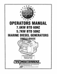
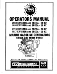
'OPERATORS MANUAL
D·NET DIESEL GENERATORS
-
-
33KW EDE • 60Hz
26KW EDE • 50Hz
25.5KW
. 21.0KW
28.5KW EDE • 60Hz
23.5KW EDE • 50Hz
EDE • 60Hz
EDE·· 50Hz
WESTERBEKE CORPORATION -150 JOHN HANCOCK ROAD
MYLES STANDISH INDUSTRIAL PARK - TAUNTON MA 02780
WEB SITE: WWW.WESTERBEKECOM
.F..I"
Member Nallonal Marine Manufacturers Assocrotlon
· CALIFORNIA
PROPOSITION 65 WARNING
Marine diesel and gasoline engine
exhaust and some of its constituents
are known to the State of California
to cause cancer, birth defects,
and other reproductive harm.
A WARNING
Exhaust gasses contain Carbon Monoxide, an odorless and
colorless gas. Carbon Monoxide is poisonous and can cause
unconsciousness and death. Symptoms of Carbon Monoxide
exposure can include:
-Dizziness
- Throbbing in Temples
-Nausea
- Muscular Twitching
-Headache
- Vomiting
- Weakness and Sleepiness -Inability to Think Coherently
IF YOU OR ANYONE ELSE EXPERIENCE ANY OF THESE SYMPTOMS,
GET OUT INTO THE FRESH AIR IMMEDIATELY. If symptoms persist,
seek medical attention. Shut down the unit and do not restart
until it has been inspected and repaired.
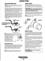
WARNING
Generators Produce CARBON MONOXIDE
Regular Maintenance Required
ri?i![~E!::!!!~~
A WARNING DECAL is provided by WESTERBEKE and
should be fixed to a bulkhead near your engine or
generator.
WESTERBEKE also recommends installing CARBON
MONOXIDE DETECTORS in the living/sleeping quarters
of your vessel. They are inexpensive and easily
obtainable at your local marine store.
Engines & Generators
SAFETY INSTRUCTIONS
INTRODUCTION
PREVENT BURNS - FIRE
Read this safety manual carefully. Most accidents are
caused by failure to follow fumkzmental rules and
A WARNING: Fire can cause injury or death!
precautions. Know when dangerous conditions exist and
take the necessary precautions to protect yourself, your
•
personnel, and your machinery.
The following safety instructions are in compliance with
the American Boat and Yacht Council (ABYC) standards.
PREVENT ELECTRIC SHOCK
A WARNING: Do not touch AC electrical connections
while engine is running, or when connected to shore
power. Lethal voltage is present at these connections!
•
•
•
•
•
•
•
Do not operate this machinery without electrical
enclosures and covers in place.
Shut off electrical power before accessing electrical
equipment.
Use insulated mats whenever working on electrical
equipment.
Make sure your clothing and skin are dry, not damp
(particularly shoes) when handling electrical equipment.
Remove wristwatch and all jewelry when working on
electrical equipment.
Do not connect utility shore power to vessels AC
circuits, except through a ship-to-shon'O double throw
transfer switch. Damage to vessels AC generator may
result if this procedure is not followed.
Electrical shock results from handling a charged
capacitor. Discharge capacitor by shorting tenninals
together.
Prevent flash fires. Do not smoke or permit flames or
sparks to occur near the carburetor, fuel line, filter, fuel
pump, or other potential sources of spilled fuel or fuel
vapors. Use a suitable container to catch all fuel when
removing the fuel line, carburetor, or fuel filters.
• Do not operate without a Coast Guard Approved flame
arrester. Backfire can cause severe injury or death.
• Do not operate with the air cleaner/silencer removed.
Backfire can cause severe injury or death.
• Do not smoke or pennit flames or sparks to occur near
the fuel system. Keep the compartment and the
engine/generator clean and free of debris to minimize the
chances of fire. Wipe up all spilled fuel and engine oil.
• Be aware - diesel fuel will bum.
PREVENT BURNS - EXPLOSION
A WARNING: Explosions from fuel vapors can cause
injury or death!
•
•
•
•
PREVENT BURNS - HOT ENGINE
A WARNING: Do not touch hot engine parts or
exhaust system components. A running engine gets
very hot!
•
•
•
•
Always check the engine coolant level at the coolant
recovery tank.
A WARNING: Steam can cause injury or death!
•
•
In case of an engine overheat, allow the engine to cool
before touching the engine or checking the coolant.
Follow re-fueling safety instructions. Keep the vessels
hatches closed when fueling. Open and ventilate cabin
after fueling. Check below for fumes/vapor before
running the blower. Run the blower for four minutes
before starting your engine.
All fuel vapors are highly explosive. Use extreme care
when handling and storing fuels. Store fuel in a
well-ventilated area away from spark-producing
equipment and out of the reach of children.
Do not fill the fuel tank(s) while the engine is running.
Shut off the fuel service valve at the engine when servicing
the fuel system. Take care in catching any fuel that might
spill. DO NOT allow any smoking, open flames, or other
sources of fire near the fuel system or engine when
servicing. Ensure proper ventilation exists when servicing
the fuel system.
Do not alter or modify the fuel system.
Be sure all fuel supplies have a positive shutoff valve.
Be certain fuel line fittings are adequately tightened and
free of leaks.
Make sure a fire extinguisher is installed nearby and is
properly maintained. Be familiar with its proper use.
Extinguishers rated ABC by the NFPA are appropriate
for all applications encountered in this environment.
Engines & Generators
SAFETY INSTRUCTIONS
ACCIDENTAL STARTING
TOXIC EXHAUST GASES
A WARNING: Accidental starting can cause injury
A WARNING: Carbon monoxide (CO) is a deadly gas!
or death!
•
Ensure that the exhaust system is adequate to expel gases
discharged from the engine. Check the exhaust system
regularly for leaks and make sure the exhaust
manifolds/water-injected elbow is securely attached.
• Be sure the unit and its surroundings are well ventilated.
Run blowers when running the generator set or engine.
• Do not run the generator set or engine unless the boat is
equipped with a functioning marine carbon monoxide
detector that complies with ABYCA-24. Consult your
boat builder or dealer for installation of approved
•
Disconnect the battery cables before servicing the engine/
generator. Remove the negative lead first and reconnect
it last.
• Make certain all personnel are clear of the engine before
starting.
• Make certain all covers, guards, and hatches are
re-installed before starting the engine.
BATTERY EXPLOSION
detectors.
A WARNING: Battery explosion can cause injury
•
or death!
•
Do not smoke or allow an open flame near the battery
being serviced. Lead acid batteries emit hydrogen, a
highly explosive gas, which can be ignited by electrical
arcing or by lit tobacco products. Shut off all electrical
equipment in the vicinity to prevent electrical arcing
during servicing.
• Never connect the negative (-) battery cable to the
positive (+) connection tenninal of the starter solenoid.
Do not test the battery condition by shorting the terminals
together. Sparks could ignite battery gases or fuel vapors.
Ventilate any comparttnent containing batteries to prevent
accumulation of explosive gases. To avoid sparks, do not
disturb the battery charger connections while the battery
is being charged.
• Avoid contacting the tenninals with tools, etc., to prevent
bums or sparks that could cause an explosion. Remove
wristwatch, rings, and any other jewelry before handling
the battery.
• Always tum the battery charger off before disconnecting
the battery connections. Remove the negative lead first
and reconnect it last when disconnecting the battery.
A WARNING: Carbon monoxide (CO) is an invisible
odorless gas. Inhalation produces flu·like symptoms,
nausea or death!
•
Do not use copper tubing in diesel exhaust systems. Diesel
fumes can rapidly destroy copper tubing in exhaust
systems. Exhaust sulfur causes rapid deterioration of
copper tubing resulting in exhaust/water leakage.
• Do not install exhaust outlet where exhaust can be drawn
through portholes, vents, or air conditioners. If the engine
exhaust discharge outlet is near the waterline, water could
enter the exhaust discharge outlet and close or restrict the
flow of exhaust. Avoid overloading the craft.
• Although diesel engine exhaust gases are not as toxic as
exhaust fumes from gasoline engines, carbon monoxide
gas is present in diesel exhaust fumes. Some of the
symptoms or signs of carbon monoxide inhalation or
poisoning are:
Vomiting
Inability to think coherently
Throbbing in temples
Dizziness
Muscular twitching
Headache
Nausea
Weakness and sleepiness
BATTERY ACID
A
WARNING: Sulfuric acid in batteries can cause
severe injury or death!
•
For additional information refer to ABYC T-22
(educational information on Carbon Monoxide).
AVOID MOVING PARTS
A WARNING: Rotating parts can cause injury
When servicing the battery or checking the electrolyte
level, wear rubber gloves, a rubber apron, and eye
protection. Batteries contain sulfuric acid which is
destructive. If it comes in contact with your skin, wash it
off at once with water. Acid may splash on the skin or
into the eyes inadvertently when removing electrolyte
or death!
•
caps.
Do not service the engine while it is running. If a
situation arises in which it is absolutely necessary to
make operating adjustments, use extreme care to avoid
touching moving parts and hot exhaust system
components.
-..y'
WESTERBEKE
Engines & Generators
ii
SAFETY INSTRUCTIONS
ABYC, NFPA AND USCG PUBLICATIONS FOR
INSTALLING DIESEL ENGINES
•
Do not wear loose clothing or jewelry when servicing
equipment; tie back long hair and avoid wearing loose
jackets, shirts, sleeves, rings, necklaces or bracelets that
could be caught in moving parts.
• Make sure all attaching hardware is properly tightened.
Keep protective shields and guards in their respective
places at all times.
• Do not check fluid levels or the drive belts tension while
the engine is operating.
• Stay clear of the drive shaft and the transmission coupling
when the engine is running; hair and clothing can easily
be caught in these rotating parts.
Read the following ABYC, NFPA and USCG publications
for safety codes and standards. Follow their
recommendations when installing your engine.
ABYC (American Boat and Yacht Council)
"Safety Standards for Small Craft"
Order from:
ABYC
3069 Solomon's Island Rd.
Edgewater, MD 21037
NFPA (National Fire Protection Association)
"Fire Protection Standard for Motor Craft"
Order from:
NFPA
11 Tracy Drive
Avon Industrial Park
Avon, MA 02322
USCG (United States Coast Guard)
"USCG 33CFR183"
Order from:
U.S. Government Printing Office
Washington, D.C. 20404
HAZARDOUS NOISE
A WARNING: High noise levels can cause hearing
loss!
•
•
•
Never operate an engine without its muffler installed.
Do not run an engine with the air intake (silencer)
removed.
Do not run engines for long periods with their enclosures
open.
A WARNING: 00 not work on machinery when you are
mentally or physically incapaCitated by fatigue!
OPERATORS MANUAL
Many of the preceding safety tips and warnings are repeated
in your Operators Manual along with other cautions and
notes to highlight critical information. Read your manual
carefully, maintain your equipment, and follow all safety
procedures.
GASOLINE ENGINE AND GENERATOR INSTALLATIONS
Preparations to install an engine should begin with a
thorough examination of the American Boat and Yacht
Council's (ABYC) standards. These standards are a
combination of sources including the USCG and the NFPA.
Sections of the ABYC standards of particular interest are:
H-2 Ventilation
P-l Exhaust Systems
P-4 Inboard Engines
E-9 DC Electrical Systems
All installations must comply with the Federal Code of
Regulations (FCR).
~
WESTERBEKE
Engines & Generators
iii
INSTALLATION
When installing WESTERBEKE engines and generators it is important that strict
attention be paid to the following information:
CODES AND REGULATIONS
Strict federal regulations, ABYC guidelines, and safety codes must be complied with
when installing engines and generators in a marine environment.
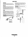
SIPHON-BREAK
For installations where the exhaust manifold/water injected exhaust elbow is close to
or will be below the vessel's waterline, provisions must be made to install a siphonbreak in the raw water supply hose to the exhaust elbow. This hose must be looped a
minimum of 20" above the vessel's waterline. Failure to use a siphon-break when
the exhaust manifold injection port is at or below the wad waterline will resull in
raw water damage to the engine and possihl£ flooding of the boat.
If you have any doubt about the position of the water-injected exhaust elbow relative
to the vessel's waterline under the vessel's various operating conditions, install a
siphon-break.
NOTE: A siphon-break requires periodic inspection and cleaning to ensure proper
operation. Failure to properly maintain a siphon-break can result in catastrophic
engine damage. Consult the siphon-break manufacturer for proper maintenance.
EXHAUST SYSTEM
The exhaust hose must be certified for marine use. The system must be desigued to
prevent water from entering the exhaust under any sea conditions and at any angle
of the vessels hull.
Adetailed 40 page Marine Installation Manual covering gasoline and
diesel, engines and generators, is available from your WESTERBEKE
dealer.
Engines & Generators
iv
AVAILABLE FROM
YOUR WESTERBEKE
DEALER
TABLE OF CONTENTS
Parts Identification ...................................................2
Introduction ................................................................3
Fuel, Engine Oil and Engine Coolant ......................... 5
Preparations for Initial Start ......................................6
Oigital Control Panel ..................................................7
Remote Stop/Start Panel ......................................... 8A
Generator Break·ln Procedure ...................................9
Daily Routine ..............................................................9
Maintenance Schedule (Chart) ................................ 10
Fuel System ..............................................................12
Cooling System .........................................................13
Raw Water Intake Strainer. ................................ 15
Draining the Raw water System ........................ 13
Fresh Water Cooling Circuit .............................. 14
Changing the Coolant... ...................................... 14
Thermostat. ......................................................... 15
Raw Water Cooling Circuit... ............................. 16
Heat Exchanger .................................................. 16
Raw Water Pump ............................................... 16
Engine Lubricating 011 .............................................. 17
Engine Oil Change ............................................. 17
Remote Oil Filter (Optional) .............................. .18
Starter Motor (Troubleshooting) ............................... 19
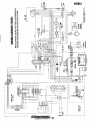
Wiring Diagram #52413 ............................................ 21
Engine Troubleshooting (Chart) ................................ 22
Alternator Testing .....................................................24
Battery Care ....................................................... 24
Glow Plugs ................................................................27
Wiring Diagrams ....................................................... 20
Engine Troubleshooting (Chart) ................................22
Alternator Testing .....................................................24
Battery Care ....................................................... 26
Glow Plugs ................................................................27
Engine Adjustments ..................................................28
Oil Pressure ........................................................ 28
Engine Compression .......................................... 28
Valve Adjustment ............................................... 28
Drive Belt Adjustment ....................................... 29
Fuel Injectors ...................................................... 29
Magnetic Plck·Up ...........................................................30
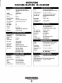
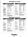
Generator Specifications ..............................................31
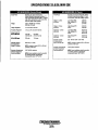
Generator Information .................................................. .33
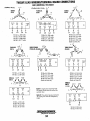
Twelve Lead Wiring Connections ................................ 34
Generator Voltage Adjustment ................................... .35
Electronic Regulation ................................................... .36
Internal Wiring Diagram ................................................37
Exciter Rotor/Rotating Field ........................................ .38
Shore Power Transfer Switch ................................... 39
Lay·Up and Recommissioning ................................. .40
Metric Conversion Data (Chart) .............................. .42
Suggested Spares .................................................... .4 3
Water Heater Connections (Optional) ..................... .44
Engines & Generators
1
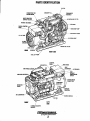
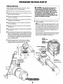
PARTS IDENTIFICATION
OIL FILL
CONNECTION FOR
SIPHON BREAK
COOLANT
THERMOSTAT
DIGITAL CDNTROL
PANEL
f--~INJIECTION PUMP
1lc::::LI.L---11AW WATER PUMP
Fl 8A FUSE
[J..e--- DIL DRAIN HOSE
REAR
RIGHT SIDE
FUEL LIFT
CONTROL
HEAT
AIR INTAKE .,LtN.'tH_"
BREAKER
HIGH
EXHAUST
TEMPERATUR£
SWITCH
AIR BLEED PETCOC:Ki.:~
SYPHON BREAK
CONNECTION
DRIVE
COVER
. DC ALTEIINAnIR-----
'"n."•• MOTOR
LEFT
SIDE
FRDNT
FLEXIBLE ISOLATED
MOUNTS
Engines & Generators
2
INTRODUCTION
PRODUCT SOFTWARE
This WESlERBEKE Diesel Generator is a product of
WESlERBEKE's long years of experience and advanced
technology. We take great pride in the superior durability and
dependable performance of our engines and generators.
Thank you for selecting WES1ERBEKE.
In order to get the full use and benefit from your generator,
it is importan~ that you operate and maintain it correctly.
This manual is designed to help you do this. Please read this
manual carefully and observe all the safety precautions
throughout. Should your engine require servicing, contact
your nearest WES1ERBEKE dealer for assistance.
This is your operators manual. A parts catalog is also
provided and a technical manual is available from your
WES1ERBEKE dealer. If you are planning to install this
equipment, contact your WES1ERBEKE dealer for
WES1ERBEKE'S installation manual.
Product software, (technical data, parts lists, manuals,
brochures and catalogs), provided from sources other than
WESTERBEKE are not within WESTERBEKE's control.
WESTERBEKE CANNOT BE RESPONSIBLE FOR THE
CONTENT OF SUCH SOFTWARE, MAKES NO WARRANTIES OR REPRESENTATIONS WITH RESPECT
THERETO, INCLUDING ACCURACY, TIMELINESS OR
COMPLETENESS THEREOF AND WILL IN NO EVENT
BE LIABLE FOR ANY TYPE OF DAMAGE OR INJURY
INCURRED IN CONNECTION WITH OR ARISING OUT
OF THE FURNISHING OR USE OF SUCH SOFTWARE.
WES1ERBEKE customers should keep in mind the time
span between printings of WES1ERBEKE product software
and the unavoidable existence of earlier WES1ERBEKE
product software. The product software provided with
WES1ERBEKE products, whether from WES1ERBEKE or
other suppliers, must not and cannot be relied upon exclusively as the definitive authority on the respective prodtict.Jt
not only makes good sense but is imperative that appropriate
representatives ofWES1ERBEKE or the supplier in question
be consulted to determine the accuracy and currentness of the
product software being consulted by the customer.
WARRANTY PROCEDURES
Your WESTERBEKE Warranty is included in a separate
folder. If, after 60 days of SUbmitting the Warranty Registry
fonn you have not received a customer identification card
registering your warranty, please contact the factory in
writing with model information, including the unit's
serial number and cOnun1ssion date.
PROTECTING YOUR INVESTMENT
Customer Identification Card
Care at the factory during assembly and thorough testing
have resulted in a WES1ERBEKE generator capable of
many thousands of hours of dependable service. However the
manufacturer cannot control how or where the generator is
installed in the vessel or the manner in which the unit is
operated and serviced in the field. This is up to the
buyer/owner-operator.
''''''''WESTERBEKE
I
Customer Identification
MR. GENERATOR OWNER
MAINS1REET
HOMETOWN, USA
Model
Ser. #
Expires
NOTE: Six imponant steps to ensure long generator life:
• Proper engine and generator installation and alignment.
• An efficient weU·designed exhaust system that includes
an anti-siphon break to prevent water from entering the
engine.
NOTES, CAUTIONS AND WARNINGS
• Changing the engine oil and oil filters according to the
maintenance schedule.
As this manual takes you through the operating procedures,
maintenance schedules, and troubleshooting of your marine
engine, critical information will be highlighted by NOTES,
CAUTIONS, and WARNINGS. An explanation follows:
• Proper maintenance of all engine and generator compo·
nents according to the maintenance scheduk in this
manual
NOTE: An operating procedure essential to note.
• Use clean, filtered unleaded fueL
A CAUTION: Procedures which, If not strictly
• Winterize your engine according to the "Lay-up and
Recommissioning" section in this manual.
ohsorved, can result In the damage or destruction of
your engine.
A WARNING: Procedures which, If not properly
followed, can result In pelSonal injury or loss of life.
~
WESTERBEKE
Engines & Generators
3
INTRODUCTION
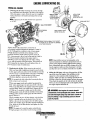
SERIAL NUMBER LOCATION
NOTE: A carbon monoxide warning decal has been provided
by WESTERBEKE. Affix this decal in a visible position in the
The engine's model number and serial number are located on
a nameplate mounted on the side of the engine.
The engine's serial number can also be found stamped into
the engine block on the flat surface of the block just above
and inboard of the injection pump. Take the time to enter this
information on the illustration of the nameplate shown below,
as this will provide a quick reference when seeking technical
informatio~ and/or ordering repair parts.
engine room.
UNDERSTANDING THE DIESEL ENGINE
The diesel engine closely resembles the gasoline engine,
since the mechanism is essentially the same. The cylinders
are arranged above a closed crankcase; the crankshaft is of
the same general type as that of a gasoline engine; and the
diesel engine has the same types of valves, camshaft, pistons,
connecting rods and lubricating system.
p
Therefore, to a great extent, a diesel engine requires the
same preventive maintenance as a gasoline engine. The
most important factors are proper ventilation and proper
maintenance of the fuel, lubricating and cooling systems.
Replacement of fuel and lubricating filter elements at the
time periods specified is a must, and frequent checking for
contamination (that is, water, sediment, etc.) in the fuel
system is also essential. Another important factor is the use
of the same brand of high detergent diesel lubrication oil
designed specifically for diesel engines.
The diesel engine does differ from the gasoline engine,
however, in its method of handling and firing of fuel. The
carburetor and ignition systems are done away with and in
their place is a single component - the fuel injection pump which performs the function of both.
ORDERING PARTS
Whenever replacement/service parts are needed, always
provide the generator model number, engine serial number,
and generator serial number as they appear on the silver and
black narae plate located on the generator end. You must
provide us with this infonnation so we may properly identify
your generator set. In addition, include a complete part
description and part number for each part needed (see the
separately furnished Parts List). Also insist upon
WESTERBEKE packaged parts because will fit or generic
parts are frequently not made to the sarae specifications as
original equipment.
SPARES AND ACCESSORIES
Certain spares will be needed to support and maintain your
WESTERBEKE generator. Your local WESTERBEKE
dealer will assist you in preparing an inventory of spare parts.
See the SPARE PARTS page in this manual. For Engine and
Generator Accessories, see the ACCESSORIES brochure.
An identification plate on the top of the engine air intake also
displays the engine model and serial number.
INSTALLATION MANUAL
CARBON MONOXIDE DETECTOR
Publication #43400 provides detailed information for
installing generators.
WESTERBEKE recommends mounting a carbon monoxide
detector in the vessels living quarters. Carbon monoxide,
even in small amounts, is deadly.
The presence of carbon monoxide indicates an exhaust leak
from the engine or generator or from the exhaust
elbow/exhaust hose, or the fumes from a nearby vessel are
entering your boat.
If carbon monoxide is present, ventilate the area with clean
air and correct the problem immediately!
Engines & Generators
4
DIESEL FUEL, ENGINE OIL AND ENGINE COOLANT
DIESEL FUEL
ENGINE COOLANT
Use fuel that meets the requirements or specification of Class
2-D (ASTM), and has a cetane rating of #4S or better.
WESTERBEKE recommends a mixture of SO% antifreeze
and SO% distilled water. Distilled water is free from the
chemicals that can corrode internal engine surfaces.
The antifreeze perfoons double duty. It allows the engine to
run at proper temperatures by transfemng heat away from
the engine to the coolant, and lubricates and protects the
cooling circuit from rust and corrosion. Look for a good
quality antifreeze that contains Supplemental Cooling
Additives (SCAs) that keep the antifreeze chemically
balanced, crucial to long teon protection.
The distilled water and antifreeze should be premixed before
being poured into the cooling circuit.
Care Of The Fuel Supply
Use only clean diesel fuel! The clearance of the components
in your fuel injection pump is very critical; invisible dirt
particles which might pass through the filter can damage
these finely finished parts. It is important to buy clean fuel,
and keep it clean. The best fuel can be rendered
unsatisfactory by careless handling or improper storage
facilities. To assure that the fuel going into the tank for your
engine's daily use is clean and pure, the following practice is
advisable:
Purchase a well-known brand of fuel. The use of additives to
combat BACTERIAL growth in the fuel tank is recommended such as Bio-Bor and an additive such as Diesel
Kleen + Cetane Boost to restore lubricity back into the fuel
when an Ultra Low Sulfur diesel is being used.
Install and regularly service a good, visual-type fuel
filter/water separator between the fuel tank and the engine.
The Raycor SOO MA or 230 RMAM are good examples of
such filters.
NOTE: Look/or the /lew environmelltallyjriendly long lasting
antifreeze that is now available.
PURCHASING ANTIFREEZE
Rather than preparing the mixture, WESTERBEKE
recommends buying the premixed antifreeze so that so that
when adding coolant the mixture will always be correct.
There are two common types of antifreeze, Ethylene Glycol
(green) and Propylene Glycol (red/purple), either can be used
but do not mix the two and if changing from one to another,
flush the engine thoroughly.
Premixed antifreeze for DIESEL Engines:
Specification #ASTM 053456.
ENGINE DlL
Use a heavy duty diesel oil with an API classification of
CF, CG-4, CH-4 or CI-4. Change the engine oil and filter
after the initial SO hours of break-in operation. Then follow
the oil and filter change intervals as specified in the
MAINTENANCE SCHEDULE in this manual.
The use of synthetic oil is peonited ONLY after the initial
break-in period of SO hours of engine operation has been
achieved.
A
MAINTENANCE
Change the engine coolant every five years regardless of the
number of operating hours as the chemical additives that
protect and lubricate the engine have a limited life.
COOLANT RECOVERY TANK
The coolant recovery tank allows for the expansion and
contraction of the engines coolant during engine operation
without introducing air into the system. This recovery tank is
provided with fresh water cooled models and with the fresh
water coolant conversion kit and must be installed before
operating the engine.
CAUTION: 00 not allow two or more brands of
engine 011 to mix. Each brand contains Its own additives;
additives of different brands could react in the mixture
to produce properties harmful to your engine.
SAE Oil Viscosity Grades
For all temperature ranges:
SAE lOW-30 or SAE ISW-40
~
WESTERBEKE
Engines & Generators
5
Revised November 2009
PREPARATIONS FOR INITIAL START-UP
PRESTART INSPECTION
A
Before starting your generator for the fIrst time or after a
prolonged layoff, check the following items:
CAUTION: When starting the generator, it is
recommended that aI/ AC loads, espeCially large
motors, be switched OFF until the engine has come
up to speed and, in cold climates, starts to warm up.
This precaution will prevent damage caused by
unanticipated operation of the AC machinery and will
prevent a cold engine from stalling,
• Make certain the cooling water thru-hull petcock is open.
• Check the engine oil level: add oil to maintain the level at
the full mark on the dipstick.
• Check the fuel supply and examine the fuel fIlter/separator
bowls for contaminants.
• Check the DC electrical system. Inspect wire connections
and battery cable connections.
• Check the coolant level in both the plastic recovery tank
and at the manifold.
• Check load leads for correct connections as specifIed in
the wiring diagrams.
NOTE: After the initial running oj the generator, the air in
the engine s cooling system will be purged to the coolant
recovery tank. Open the air bleed petcock to ensure that
the cooling system is purged oj air. After shutdown and
after the engine has cooled, the coolant Jrom the recovery
tank will be drawn into the engine s cooling system to
replace the purged air.
• EXamine the air inlet and outlet for air flow obstructions
(Soundguard).
• Be sure no other generator or utility power is connected to
the load lines.
• Be sure that in power systems with a neutral line that the
neutral is properly grounded (or ungrounded) as the system
requires, and that generator neutral is properly connected
to the load neutral. In single phase systems an incomplete
or open neutral can supply the wrong line-to-neutral voltage on unbalanced loads.
BeJore subsequent operation oJthe generator, the engines
manifold should be topped off, and the coolant recovery
tank may need to be filled to the MAX level.
COOLANT
RECOVERY TANK
• Visually examine the unit. Look for loose or missing
parta, disconnected wires, unattached hoses, and check
threaded connections. Search for any fuet leaks.
__
~I
'i'
MAINTAIN
COOlANT LEVEL
AT 1/2 FULL
OIL FILL
~~/
II
OIL FILTER~
V~~2(1"~::S~lg~OIL
FILL
Ii
Lv<,M",uABOVE
OIL FILTER
& Generators
6
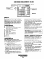
DIGITAL CONTROL PANEL
NOTE: During operation the color
of the LCD display may vary.
Caused by heat, this is nomwi
and no cause for concern
CONTROL BOX
B AMP FUSE
PROTECTS THE PANEL
ELECTRONICS FROM A
HIGH AMP UVt,HLlIAU_-L '" I f'",/C~'"
__ "cARROW
_~8GtIULL
IL___
LOCK
·DO\~NARROW
INDICATOR LIGHTS ---1----1__ PRIIME BUTTON
ENERGIZES THE FUEL PUMP
20 AMP DCCClllCUIT--r1l"1'
BREAKER
- _.•TOne
~.T"DT
DESCRIPTION
WESTERBEKE'S' Digital Control Panel provides the
operator with an LCD display that continuously monitors
all the operations of the generator in easy to understand
text messages.
BUTTON
BUTTON
Battery Voltage
Oil Pressure
13.5 vqc
40 PSI
•
30
o
100
SCROLL
SCROLL.
NOTE: Operating temperatures may cause the LCD display
to vary in color. This is nonnal and a change in color will
not affect the operation of the control panel.
START SEQUENCE'
With the pre-start inspection completed, press the START
button and the automatic sequence will begin. The six
indicator lights will illuntinate green and th~ panel will
display the following text:
AC Frequency
3.8 HOURS.
59.4
AC Phase Voltage
A.
119 V.
Press start to
B.
121 V.
Engines & Cienerators
engage generator
Pre Heatil)g ......
7 Seconds
SCROLL
SCROLL
. Waiting for operator
fW'IWESTERBEKE
I
Engine Hours
AC Line Voltage
240 V.
SCROLL
, . LOCK
SCROLL LOCK
To stop the continuing sequence, press the SCROLL LOCK
button. This enables the operator to monitor a single function
for any length of time. The word LOCK will appear in the
comer. Use the up and down arrows to find and observe other
functions. To resume scrolling, press the SCROLL LOCK
button again.
Cranking ......
Up and Down Arrows
When the display is in its cycling mode, the UP and Down
arrows can be used to adjust the dark and light contrast of the
screen.
RUN SEQUENCE
As the display cycles thru the engine functions, the speed
will come up to 1800 rpm's-60Hz (1500rmp's-50Hz) and oil
pressure and engine coolant will rise to their normal readings. The functions will cycle in the following sequence:
Engine Speed
Use the PRIME button on the digital control panel to purge
air and bring fuel back into the fuel lines after perfornting
fuel filter maintenance.
. Coolant Temperature
1800 RPM
o
FUEL PRIMING
172F
.::oJ
2500
.SCROLL
o
"
LCD DISPLAY
!
30.
Periodically clean the control panel and its LCD screen using
a soft cloth .
.SCROLL
Engines & Generators
7
DIGITAL CONTROL PANEL
Examples:
STOP SEQUENCE
Failure Light is red.
Coolant Temperature Light is orange.
To stop the generator, press the S1DP button. The d,isplay
will cycle thru the following text messages and shutdown.
High Engine Temp.
Waiting for operator
Shutting
Down
Press start to
Reset ECU to ReStart
engage generator
Engine Shutdown
Failure Light is red.
Oil Pressure Light is orange.
THE CONTROL PANEL WILL POWER-DOWN
AND IN A FEW MOMENTS THE DISPLAY
WILL GO BLANK
Low Oil Pressure
Reset ECU to Restart
FAILURE LIGHT/SHUTDOWN
When a failure occurs, refer to the troubleshooting chart,
wiring diagram, and general operating text in this manual to
assist in solving the trouble.
There are many combinations of messages that can be
displayed but they are all self explanatory and the operator
can easily isolate and correct the problem should one occur.
Before restarting the generator, the 20 amp DC circuit
breaker must be pushed to the OFF position, and back to the
ON position to reset the ECD. Once the problem is corrected
and the generator is restarted, the LCD display will begin
cycling again.
If a problem occurs, the generator will shutdown and the
FAILURE light will illuminate red. In addition, one of the
indicator lights will change from green to orange to reveal
where the trouble has occurred and the display will text
message what has happened.
CAUTION: When servicing/changing DC components.
The DC power most be turned off using
either the DC breaker or the battery switch.
CHANGING FREQUENCY
(DC breaker must be off)
When changing the generators
frequency (SO/60Hz) switch #f
on the ECU board must be
positioned: ON lor 50Hz
OFF lor 60Hz
CONTROL BOX
INTERNAL COMPONENTS .
CAUTION (WESTERLINK or NMEA·2000):
The electronic components in the Digital
Diesels draw a very small amount of
amperage (milli-amps)from the
generator's starting battery when the
unit is in a static state. This maybe as
much as 50 mtlli-amps for the system
ECU and 50 niil~!-ampsfor each display.
This can he as mitch as 72 amp-hours in a months
time with no generator use. It is not necessary to be
concerned with this slight amperage draw during normal
seaso"al use. However, if the generator set is not to be
used for a number of months, such as winter storage, it is
best 10 disconnect the DC power to the generator with a
NMEA-2000 system -or shut off the .DC breaker OIl the
generator's control boxfor a WESTERLINK system.
NOTE: Keep in mind that the Westerbc:ke gener:ator maybe
the DC power supply for the vessel's NMEA~2000 network.
LCD DISPLAY PANEL
- ...
NOTE: DURING OPERATION THE COWR
I':;;..=J
~~~;
8
OF THE LCD DISPlAY MAY VARY.
CAUSED BY HEAT. THIS IS NORMAL
AND NO CAUSE FOR CONCERN.
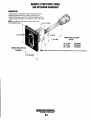
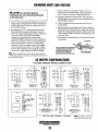
REMOTE STOP/START PANEL
AND EXTENSION HARNESSES
DESCRIPTION
A remote panel is available that allows the generator to be
stopped and started from any location on the boat. The
connecting harnesses come in three different lengths and two
of these can be combined for a maximum run at 75' (22.17M).
NOTE: For additional information, contact your local
WESTERBEKE dealer.
3·1/4" (82.!55MIII)
6" (152.4MM)
15' (4.75M)
30' (9.1M)
60' (18.2M)
REMOTE PANEI../PIG TA II
PN052560
CONNECTING EXTENSION
CABLES
~
PN 052959
PN 052789
PN 052960
These two dimensions are the measurement of the cut-out opening.
-'.~~
~
WESTERBEKE
Engines & Generators
B'A
GENERATOR BREAK-IN PROCEDURE
DESCRIPTION
After the first 10 hours of the generator's operation, the load
can be increased to the full-load rated output, then periodically vary the load.
Although your engine has experienced a minimum of one
hour of test operations at the factory to make sure accurate
assembly procedures were followed and that the engine
operated properly, a break-in time is required. The service
life of your engine is dependent upon how the engine is
operated and serviced during its initial hours of use.
Avoid overload at all times. An overload is signaled by smoky
exhaust with reduced output voltage and frequency. Monitor
the current being drawn from the generator and keep it within
the generator's rating. Since the generator operates at 1800
rpm to produce 60 hertz (or at 1500 rpm to produce 50
Hertz), control of the generator's break-in is governed by the
current drawn from the generator.
Breaking-in a new engine basically involves seating the
piston rings to the cylinder walls. Excessive oil consumption
and smoky operation indicate that the cylinder walls are
glazed or scored, which is caused by overloading the
engine during the break-in period.
Your new engine requires approximately 50 hours of initial
conditioning operation to break in each moving part in order
to maximize the performance and service life of the engine.
Perform this conditiOning carefully, keeping in mind the
following:
NOTE: Be aware oImotor starting loads and the high current
draw requiredfor starting motors. This starting amperage
draw can be 3 to 5 times normal running amperage. See
GENERATOR INFORMATION in this manual.
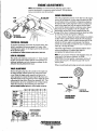
GENERATOR ADJUSTMENTS
Once the generator has been placed in operation, there may be
governor adjustments required for engine speed (hertz) during
the engine's break-in period (first 50 hours) or after this
period see ENGINE SPEED (HERTZ) ADJUSTMENT) under
ENGINE ADJUSTMENTS.. A no-load voltage adjustment
may also be required in conjunction with the engine's speed
adjustment see GENERATOR INFORMATION.
Start the engine according to the STARTING PROCEDURE
section. Run the engine while checking that all systems (raw
water pump, oil pressure,. battery charging) are functioning.
AFTER START·UP
Once the generator has been started, check for proper operation and then encourage a fast warm-up. Run the generator
between 20% and 60% of full-load for the first 10 hours.
THE DAILY ROUTINE
CHECK LIST
NOTE: Some unstable running may occur in a cold engine.
Follow this check list each day before starting your generator.
This condition should abate as normal operating temperature
is reached and loads are applied.
• Check that all generator circuit breakers (power panel) are
in the off position before starting.
A CAUTION: 00 not operate the generator for long
• Record the hourmeter reading in your log (engine hours
relate to the maintenance schedule.)
periods of time without a load being placed on the
generator.
Any deficiency or problems in the following items must
be corrected before start up.
STOPPING THE GENERATOR
• Visually inspect the engine for fuel, oil, or water leaks.
Remove the AC loads from the generator one at a time.Allow
the generator to run for 3-5 minutes to stabilize the operating
temperature, then momentarily depress the stop button and
release. The generator wiII automatically shut down. Tum off
the DC circuit breaker to prevent unintentional starts as a
safety precaution.
• Check the oil level (dipstick).
• Check the coolant level in the coolant recovery tank.
• Check your fuel supply.
• Check the starting batteries (weekly).
• Check drive belts for wear and proper tension (weekly).
CHECK WITH THE ENGINE RUNNING.
• Check for abnormal noise such as knocking, vibrating and
blow-back sounds.
• Confirm exhaust smoke:
When the engine is cold - White Smoke.
When the engine is warm - almost Smokeless.
When the engine is overloaded - some Black Smoke.
-.,.y-
WESTERBEKE
Engines & Generators
9
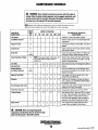
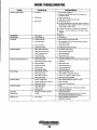
MAINTENANCE SCHEDULE
A
WARNING: Never attempt to perform any service while the engine is
running. Wear the proper safety equipment such as goggles and gloves, and
use the co"ect tools for each job. Disconnect the battery terminals when
servicing any of the engine's DC electrical equipment.
NOTE: Many of the following maintenance jobs are simple but others are more
difficult and may require the expert knowledge of a service mechanic.
SCHEDULEO
MAINTENANCE
Fuel Supply
CHECK
EACH
DAY
HOURS OF OPERATION
50
100
250
500
EXPLANATION OF SCHEDULED
MAINTENANCE
750 1000 1250
Diesel No.2 rating of 45 cetane or higher.
Fuel/Water Separator
0
0
Engine Oil Level
0
Oil level should indicate between MAX. and LOW on
dipstick.
Coolant Level
0
Check at recovery tank; if empty, check at manifold.
Add coolant if needed.
0
Inspect for proper tension (3/8' to 112' depression)
and adjust if needed. Check belt edges for wear.
Drive Belts
Check for water and dirt in fuel (drain/replace filter
if necessary).
weekly
Visual Inspection of Engine
0
NOTE: Please keep engine surface clean. Dirt
and oil will inhibit the engine's ability to
remain cool.
Fuel Filter
0
0
0
Inlet Fuel Filter
Starting Batteries
(and House BaUeries)
0
0
0
0
Initial change at 50 hrs, then change every 250 hrs.
Replace.
Every 50 operating hours check electrolyte levels
and make sure connections are very tight. Clean off
excessive corrosion.
0
0
Generator
0
Heat Exchanger Zinc Anode
0
FilterlWater Separator
Engine Hoses
0
0
weekly
Engine Oil (and filter)
Exhaust System
0
0
Check for fuel, oil and water leaks. Inspect wiring
and electrical connections. Keep bolts & nuts tight.
Check for loose belt tension.
0
0
0
0
0
Initial engine oil & filter change at 50 hrs., then
change both every 250 hours.
0
0
0
0
0
0
Check that AC connections are clean and secure
with no chafing. See GENERATOR MAINTENANCE
for additional information.
0
0
0
0
0
0
Inspect zinc anode, replace if needed, clear the heat
exchanger end of zinc anode debris.
0
0
0
0
0
0
0
0
0
Change the filter and/or drain water every 200 hrs.
0
0
0
0
0
Hose should be hard & tight. Replace if soft or
spongy. Check and tighten all hose clamps.
0
0
Initial check at 50 hrs., then every 250 hrs. Inspect
for leaks. Check anti-siphon valve operation. Check
the exhaust elbow for carbon andlor corrosion
buildup on inside passages; clean and replace as
necessary. Check that all connections are tight.
A
CAUTION: When servicing/changing DC
components, the DC power must be turned off using
either the DC breaker Dr the battery switch.
Engines & Generators
10
Revised November 2009
MAINTENANCE SCHEDULE
NOTE: Use the engine hour meter gauge to log your engine hours or record your
engine hours by rurming time.
SCHEDULED
MAINTENANCE
CHECK
EACH
DAY
HOURS OF OPERATION
50
Raw Water Pump
100
250
500
750 1000 1250
0
0
0
At 8{}{) operating hours,
disassemble and inspect
for overhaul.
Coolant System
Electric Fuellifl Pump
0
0
0
0
0
0
Periodically check the wiring connections and
inspect the fuel line connections.
Check and adjust injection opening pressure and
spray condition (see ENGINE ADJUSTMENTS).
0
'Fuellnjeclors
Remove the pump cover and inspect impeller,
gasket, cam and cover for wear. Check the bearings
and seals (the shaft should not wobble). Lubricate
when reassembling.
Drain, flush, and refill cooling system with the
appropriate antifreeze mix.
0
0
EXPLANATION OF SCHEDULED
MAINTENANCE
'Starler Molor
0
0
Check solenoid and motor for corrosion. Remove
and lubricate. Clean and lubricate the starter motor
pinion drive.
'Preheat Circuit
0
0
Check operation of preheat solenoid. Remove and
clean glow plugs; check resistance (4-6 ohms).
Reinstall with anti-seize compound on threads.
'Engine Cylinder
Compression
0
0
Check compression pressure and timing
(see Engine Adjustments).
'Adjust the Valve Clearances
0
Adjust Valve Clearances
(see ENGINE ADJUSTMENTS).
'Heat Exchanger
0
Remove, have professionally cleaned and pressure
tested.
0
Check casting integrity every 500 hours of
operation. Replace a3 needed.
'Water tnjected Exhaust
Elbow
0
'WESTERBEKE recommends this service be performed by an authorized mechanic.
CAUTION (WESTERLINK or NMEA-20DD): The electronic componems ill the Digital Diesels draw a very small amount of amperage (milli-amps)from the
generator's starting battery when the unit is in a static state. This maybe as much as 50 milli-ampsfor the system ECU and 50 milli-amps for each display.
This can be as much as 72 amp-hours in a months time with no generator use. It is no/necessary fa be concerned with this slight amperage draw during
normal seasonal use. However, if the generator set is not to be used for a number of months, .Hlcll as willter storage, it is best to disconnect the DC power
to the generator with a NMEA-2000 system o(shl# off the DC breaker on the generators control box for a WESTERLlNK system.
NOTE: Keep ill mind that the Westerbeke generator maybe the DC power slIpplyfor the vessels NMEA-2000 network.
A
CAUTION: When serviCing/changing DC
components. the DC power must be turned off using
either the DC breaker or the battery switch.
Engines & Generators
11
FUEL SYSTEM
DIESEL FUEL
ENGINE FUEL FILTER
Use No.2 diesel fuel with a Celane rating of 45 or higher. In
conjunction with Ultra Low Sulphur Diesel. Use an additive
such as "Diesel Kleen" produced by Power Services PS to
help restore fuel lubrication (product #3025).
Periodically check the fuel connections and the filter bowl for
leakage. Change the filter element after the first 50 houTS. See
the MAINTENANCE SCHEDULE.
Changing the Filter Cartridge
FUEL WATER SEPARATDR
1. Shut off the fuel supply.
A primary fuel filter of the water separating type must be
installed between the fuel tank and the engine to remove
water apd other contaminants from the fuel before they can
be carried to the fuel system on the engine.
NDTE: Slide a plastic bag up over the fuel filter cartridge
as it will be full offuel.
2. Unscrew the cartridge from its housing and remove the
cartridge and its gasket.
3. Wipe both the housing and the top of the new cartridge
with clean fuel.
4. To help reduce fuel system priming, fill the fuel filter
with diesel before installing. This will dramatically
reduce the priming time needed to purge air from the
engines fuel system before starting.
5. Install the new cartridge and spin on real tight by hand.
6. Open the fuel supply. Run the engine to inspect for leaks.
A typical fuel filter/water separator is illustrated in this
diagram. This is the Raycor Model 500 MA. Keep in mind
that if a water separator type filter is not installed between the
fuel supply tank and engine-mounted fuel system, any water
in the fuel will affect the fuel pump, engine filter, and injection equipment. The owner/operator is responsible for making
certain the fuel reaching the engine's injection equipment is
free of impurities. This process is accomplished by installing
and maintaining a proper filtration/separation system.
TYPICAL FUEL
FILTERJWATER
SEPARATOR
10 micron filter
element recommended.
FUEL FILTER
ASSEMBLY
LIGHTLY WIPE
WITH CLEAN FUEL
WHEN INSTALLING
THENEWFUEL
CARTRIDGE
FUEL INJECTlDN PUMP
The fuel injection pump is the most important component of
the diesel engine, requiring the utmost caution in handling.
The fuel injection pump has been thoroughly bench-tested
and the owner-operator is cautioned not to attempt to service
it If it requires servicing, remove it and take it to an
authorized fuel injection pump service facility. Do not
attempt to disassemble and repair it. Do not send the timing
shims with the injection pump, leave on engine.
BLEED SCREW
The bleed screw on the injection pump should be left in the
open position. This will then allow for ease in priming the
engine's fuel system and during engine operation allow for
air in the system to be delivered to the fuel tank through the
fuel return system.
FUEL FILTER
CARTRIDGE
INCOMING FUEL
FUEL LIFT PUMP
FUEL INJECTIDN
PUMP
. Q
Periodically check the fuel connections to and out of the
pump and make sure that no leakage is present and that the
fittings are tight and secure. The DC ground connection at
one of the pumps mounting bolts should be clean and well
secured by the mounting bolts to ensure proper pump
operations .
INLET FUEL FILTER
To ensure clean fuel into the fuel lift pump, there is a small
in-line fuel filter connected to the fuel lift pump elbow. This
filter should be replaced every 250 hours of operation.
SPEED ADJUSTMENT
FACTORY SET
EngInes & Generators
12
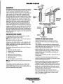
COOLING SYSTEM
DESCRIPTION
Westerbeke marine diesel engines are designed and equipped
for fresh water cooling. Heat produced in the engine by combustion and friction is transferred to fresh water coolant
which circulates throughout the engine. This circulating fresh
water coolanteools the engine block .. its internal moving
parts, and the engine oil. The heat is transferred externally
from the fresh water coolant to raw water by means of a heat
exchanger, similar in function to an automotive radiator. Raw
water flows through the tubes of the heat exchanger while
fresh water coolant flows around the tubes; engine heat transferred to the fresh water coolant is conducted through the
tube walls to the raw water which is then pumped into the
exhaust system where finally it is discharged overboard. In
other words, the engine is cooled by fresh water coolant, this
coolant is cooled by raw water, and the raw water carries the
transferred heat overboard through the exhaust system. The
fresh water coolant and raw water circuits are independent of
each other. Using only fresh water coolant within the engine
allows the cooling water passages to stay clean and free from
harmful deposits.
WASHER-:!~~Sl1
FILTER
INSPECT AND
CLEAN EVERY
100 HOURS
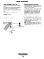
TYPICAL RAW WATER INTAKE STRAINER
(Owner Installed)
INCOMING
RAW WATER
RAW WATER INTAKE STRAINER
".- ".;
SEACOCK
A major part of the raw water cooling system is a proper
boatyardlbuilder installed intake strainer.
--=CCCO::;>- .
DRAINING THE RAW WATER SYSTEM
NOTE: Always install the strainer at or below the waterline so
the strainer will always be self-priming.
When freezing temperatures are expected, it is best to
protect the raw water cooling circuit and engine exhaust
from damage.
This procedure is best accomplished by disconnecting the
water intake hose from the vessels thru-hull fitting. Close the
intake valve before disconnecting the hose. Insert the hose
end into a large container of fresh water.
Before starting the engine, remove the engine thermostat
(replace the gasket and cover). This will ensure a full flow
of water thru the engine. Re-install the thermostat once
flushing is complete.
Run the unit for IO minutes or longer to adequately flush the
" cooling system.
Provide an external fresh water supply for the bucket to
maintain the water level in the bucket while the unit is being
operated during the flushing process.
A clean raw water intake strainer is a vital component of the
engine's cooling system. Include a visual inspection of this
strainer when making your periodic engine check. The water
in the glass should be clear.
Perform the following maintenance after every 100 hours of
operation:
1. Close the raw water seacock.
2. Remove and clean the strainer filter.
3. Clean the glass.
4. Replace the washer if necessary.
S. Reassemble and install the strainer.
6. Open the seacock.
7. Run the engine and check for leaks.
NOTE: Also follow the above procedure after having run hard
aground.
The fresh water will flush out the engines water passages and
, exhaust lines. If the engine is being stored and there is a
probability of freezing, flush the engine with fresh water and
then prior to shutting the unit down substitute the fresh water
supply with a concentrated antifreeze mixture and run this
through the engine to provide freeze and corrosion protection
for both the engine and exhaust system.
When recommissioning, make certain the valves and
seacocks are open so the engine will quickly receive fresh
water. if the engine is stowed where it is wann, the fresh
If the engine temperature gauge ever shows a higher than
normal reading, the cause may be that silt, leaves or grass
may have been caught up in the strainer, slowing the flow of
raw water through the cooling system.
water can stay in the engine.
-..: WESTERBEKE
Engines & Generators
13
COOLING SYSTEM
FRESH WATER COOLING CIRCUIT
CHANGING COOLANT
NOTE: Refer to the ENGINE COOLANT section for the rec-
The engine's coolant must be changed according to the
MAINTENANCE SCHEDULE. If the coolant is allowed to
become contaminated, it can lead to overheating problems
ommended antifreeze and water mixture to be used as the
fresh water coolant
Fresh water coolant is pumped through the engine by a circulating pump, absorbing heat from the engine. The coolant
then passes through the thermostat into the manifold, to the
heat exchanger where it is cooled, and returned to the engine
block via the suction side of the circulating pump.
When the engine is started cold, external coolant flow is prevented by the closed thermostat (although some coolant flow
is bypassed around the thermostat to prevent the exhaust
manifold from overheating). As the engine warms up, the
thermostat gradually opens, allowing full flow of the engine's
coolant to flow unrestricted to the external portion of the
~olin~ s¥stem.
TOCOOuwr
RECOVERY TANK
A CAUTION: Proper cooling system maintenance Is
crItIcal; a substantial number of engIne failures can be
traced back to cooling system corroSion.
Drain the engine coolant by loosening the drain plug on the
engine block and opening the manifold pressure cap. Flush
the system with fresh water, then start the refill process.
NOTE: The drain on the heat exchonger should also be used
to help. drain engine coolant.
ENGINE BLOCK
DRAIN
COOLANT
~~
KEEP THE
(19mm HEX)
COOLANT PASSAGE
OIL GALLERY
--fl
CLEAR
KEEP mESE PASSAGES CLEAR TO ENSURE
AFULL FLOW OF COOLANT TO ANO mOM
mE COOLANT RECOVERY TANK ( A PIPE
CLEANER WORKS WELL)
FROM coouwr
RECOVERY TANK
Refilling the Coolant
COOLANT RETRACTION
After closing the engine block drain, pour clean, premixed
coolant into the manifold and when the coolant is visible in
the manifold, start the engine and run it at slow idle. Open
the air bleed petcocks on the manifold and the thermostat
housing.
NOTE: PeriodicaUy check the condition of the manifold
pressure cap. Ensure the upper and lower rubber seals are in
good condition. Check to ensure
the vacuum valve opens and
closes tightly. CarlY a spare
cap. Check also to ensure the
coolant passage is clear so
coolant within the, system is
SEAL
able to expand and cOn1ract
to and from the coolont recovClytank
Monitor the coolant in the manifold and add as needed. Fill
the manifold to the filler neck and when the coolant flowing
from the petcock is free of air bubbles, close the petcock and
install the pressure cap.
Remove the cap on the coolant recovery tank and fill with
coolant mix to halfway between LOW and MAX and replace
the cap. Run the engine and observe the coolant expansion
flow into the recovery tank. When the petcock on the thennostat housing is free of air bubbles, close that petcock.
Coolant Recovery Tank
A coolant recovery tank allows for engine coolant expansion
and contraction during engine operation, without any significant loss of coolant and without introducing air into the cooling system. This tank should be located at or above the
engine manifold level and should be easily accessible.
A.fter Checking for leaks, stop the engine and allow it to cool.
Coolant.should draw back into the cooling system as the
engine cools down. Add coolant to the recovery tank if
needed. Clean up any spilled coolant.
A
WARNING: Beware of the hot engine coolant.
Wear protectIve gloves.
NOTE: This tank, with its short I'U1I of plastic /wse, is best
s
located at or above the level of the engine manifold.
Engines & Generators
14
COOLING SYSTEM
THERMOSTAT
REPLACING THE THERMOSTAT
A thermostat, located near the manifold at the front of the
engine. controls the coolant temperature as the coolant
continuously flows through the closed cooling circuit.
When the engine is first started, the closed thermostat prevents coolant from flowing (some coolant is by-passed
through a hole in the thermostat to prevent the exhaust
manifold from overheating). As the engine warms up, the
thermostat gradually opens. The thermostat is accessible
and can be checked, cleaned, or replaced easily. Carry a
spare thermostat and gasket.
1. Drain ofT some coolant: Release the coolant pressure cap
and drain the coolant to the approximate level off the
thermostat housing. This can be done using the heat
exchanger drain plug.
2. Rotate the thermostat assembly: Loosen the hose clamp
as shown and remove the three allen screws that hold
down the thermostat housing cover, the assembly can now
be twisted enough to access the gasket and thermostat.
3. Remove/replace the gasket and thermostat: When
installing the new parts, apply a thin coat of sealant on
both side of the gasket before pressing it into place.
LOOSEN THIS HOSE CLAMP
HEAT
EXCHANGER
COOLANT ORAIN PLUG
FROM COOLANT
RECOVERY
_
~.
~e-assemble ~t:
~
Tum the cover back into place and
tighten the three screws. Do not over-tighten! Tighten the
hose clamp and tighten the drains. Top off the coolant and
run the engine. Check for normal temperature and for any
leaks around the thermostat assembly.
-1 (
A CAUTION: The engine //Just be aI/owed to cool
down before aUempting these procedures. Not only
is the surface of the engine hot but coolant
temperatures can be at 190' F.
THERMOSTAT
ASSEMBLY
GASKET
SEAL WITH HI- TACK
rr-(,----- AIR BLEEO
PETCOCK
THERMOSTAT
HOUSING COVER
THEllMOSTATHOUSING
En.gifles & Gen.erators
15
COOLING SYSTEM
HEAT EXCHANGER
RAW WATER COOLING CIRCUIT
The raw water flow is created by a positive displacement
impeller pump. This pump draws water directly from the
ocean, lake, or river through a hose to the water strainer. The
raw water passes from the strainer through the heat
exchanger (through the heat exchanger tubes) where it cools
the engine Circulating fresh water coolant. The raw water is
then discharged into the water injected exhaust elbow, mixing with and cooling the exhaust gasses. This mixture of
exhaust gas and raw water is pushed overboard.
Raw Water Pump
BAD
CLEAN
AND
REUSE
The raw water pump is a self-priming, rotary pump with a CLEAN
non-ferrous housing and a neoprene impeller. The impeller DEBRIS. BOTH ENDS
has flexible vanes which wipe against a curved cam plate
within the impeller housing, producing the pumping action.
ZINC ANODES
Heat Exchanger
On no account should this pump be run dryas water acts as a
lubricant for the impeller. There should always be a spare
The heat exchanger is a copper tube which encloses a numimpeller and impeller cover gasket aboard (an impeller kit).
ber of small copper tubes. Raw water is pumped through the
Raw water pump impeller failures occur when lubricant (raw
small copper tubes and the freshwater coolant from the
water) is not present during engine operation. Such failures
engine is circulated around the copper tubes. The raw water
are not warrantable, and operators are cautioned to make sure
removes heat from the freshwater coolant. _
raw water flow .is J?resent at s~-up.
Zinc Anode
NOTE: Should afailure occur with the pumps internal parts
(seals and bearings), it may be more cost efficient to
purchase a new pump and rebuild the original pump as
a spare.
InspictlnglChanging the Raw Water Pump Impeller
Close the raw water intake valve. Remove the pump cover
and, with the proper size impeller tool, carefully pry the
impeller out of the pump (the impeller can be pried out using
a pair of screwdrivers if an impeller puller is unavailable. Take
care not to tear the impeller). Install the new impeller and
.gasket. Move the blades to confOnD to the curved cam plate
and push the impeller into the pumps housing. When
assembling, apply a thin coating of lubricant to the impeller
and gasket. Open the raw water intake valve.
Run the engine and check for leaks around the pump. Also
check for water discharge at the stem tube. Absence of W-ilter
flow indicates the pump has not primed itself properly.
NOTE: Never allow the pump to run dry. Even a short period
of dry running may destroy the impeller.
RAW WATER PUMP
PN 52650
A zinc anode, or pencil, is located in the raw water cooling
circuit within the heat exchanger. The purpose of the zinc
apode is to sacrifice itself to electrolysis action taking place
in the raw water cooling circuit, thereby reducing the effects
of electrolysis on other components of the system. The condition of the zinc anode should be checked monthly and the
anode cleaned or replaced as required. Spare anodes should
be carried on board.
NOTE: Electrolysis action is the result of each particular
installation and vessel location; not that of the generator.
If the zinc pencil needs replacement, hold the hex boss into
which the zinc pencil is threaded with a wrench while loosening the anode with another wrench. This prevents the hex
boss from possibly tearing off the exchanger shell. After
removing the zinc, note the condition of it. If the zinc is in
poor condition, there are probably a lot of zinc flakes within
the exchanger. Remove the end of the heat exchanger and
clean the inside of all zinc debris. Always have a spare heat
exchanger end gasket in case the present one becomes damaged when removing the end cover. Replace the gasket (refer
to your engine model's heat exchanger end gasket part number), o-ring, cover, and install a new zinc pencil.
Heat Exchanger Service
INSPECTION: CHECK THE BASE OF
EACH BLADE BY BENDING VIGOROUSLY.
REPLACE THE IMPELLER IF THERE ARE
ANY CRACKS.
After approximately 1000 hours of operation, remove, clean
and pressure test the engine's heat exchanger. (A local automotive radiator shop should be able to clean and test the heat
exchanger.)
. NOTE: Operating in silty and/or tropical waters may require
RAI""VAT.ii'<
that a heat exchanger cleaning be performed more often than
every 1000 hours.
Engines·& Generators
16
ENGINE LUBRICATING OIL
g:@
ENGINE OIL CHANGE
1. Draining the oil sump. Discharge the used oil through
the sump drain hose (attached to the front of the engine)
while the engine is warm. Drain the used oil completely,
replace the hose in its bracket and replace the end cap
securely.
NOTE: Thread size for the lube oil drain hose capped end
is 114 NFT.
Bl!:""l~-8mlm
SIDE OIL FILTER
A SlOE OIL FILL
IS LOCATED
THE OIL
APPLY CLEAN
ENGINE OIL
INSTALLING
[11/161 SOCKET
FOR EXTENSION
114" NPT
WtPE SURFACE CLEAN
BEFORE INSTALLING.
USING AN 8MM (11176') SOCKET
TO DRAtN THE OtL OR PUMP THE WARMED
OtL UP THRU THE HOSE.
\\\I<tMUV'
Always observe the used oil as it is removed. A
yellow/gray emulsion indicates the presence of water in
the oil. Although this condition is rare, it does require
prompt attention to prevent serious damage. Call a
qualified mechanic should water be present in the oiL
Raw water present in the oil can be the result of a fault in
the exhaust system attached to the engine andIor a
siphoning of raw water through the raw water cooling
circuit into the exhaust, filling the engine. This problem is
often caused by the absence of an anti-siphon valve, its
poor lOcation or lack of maintenance.
2. Replacing the oilfilter. When removing the used oil
filter, you may find it helpful and cleaner to punch a hole
in the upper and lower portion of the old filter to drain the
oil from it into a container before removing it. This helps
to lessen spillage. A small automotive filter wrench
should be helpful in removing the old oil filter.
NOTE: Do not punch this hole withoutfirst loosening the filter to
make certain it can be removed.
Place some paper towels and a plastic bag around the
filter when unscrewing it to catch any oil left in the filter.
(Oil or any other fluid on the engine reduces the engine's
cooling ability. Keep your engine clean.) Inspect the old
oil filter as it is removed to make sure that the rubber
sealing gasket comes off with the old filter. If this rubber
sealing gasket remains sealed against the filter bracket,
gently remove it.
When installing the new oil filter element, wipe the filter
gasket's sealing surface on the bracket free of oil and
apply a thin coat of clean engine oil to the rubber gasket
on the new oil filter. Screw the filter onto the threaded oil
filter nipple on the oil filter bracket, and tighten the filter
firmly by hand.
NOTE: The engine oil is cooled by engine coolant flowing
through passages in the oil filter bracket hOl/sing assembly
~
NOTE: Generic filters are not recommended, as the
material standards or diameters of important items on
generic parts might be entirely different from genuine
parts. Immediately after an oil filter change and oil fill,
run the engine to make sure the oil pressure is nonnal
and that there are no oil leaks around the new oil filter.
3. Filling the Oil Sump. Add new oil through the oil filler
cap on the top of the engine. After refilling, run the
engine for a few moments while checking the oil
pressure. Make sure there is no leakage around the new
oil filter or from the oil drain system, and stop the engme.
Then check the quantity of oil with the lube oil dipstick.
Fill to, but not over the high mark on the dipstick, should
the engine require additional oil.
A WARNING: Used engine oil contains harmful
contaminants. Avoid prolonged skin contact. Clean skin
and nails thoroughly using soap and water. Launder or
discard clothing or rags containing used oil. Discard
used oil properly.
WESTERBEKE
Engines & Generators
17
REMOTE OIL FILTER (OPTIONAL)
NOTE: Westerbeke is not responsible for engine failure due to
incorrect installation of the Remote Oil Filter.
INSTALLATION
Irhls popular accessory is used to relocate the engine's oil filiN from the engine to a more convenient location such as an
engine room bulkhead.
.
tlOTE: Refer to ENGINE OIL CHANGE in this manualfor
Instructions on removing the oil filter.
.
trb install, 'simply remove the engine oil filter and thread on
WEsTERBEKE's remote oil filter kit as shown. Always
lnstall this kit with the oil filter facing down as illustrated.
Contact your WES'IERBEKE dealer for more information.
APPLY A THIN COAT OF CLEAN OIL TO THE O·RING WHEN
INSTALLING THIS KIT. THREAD THE KIT ON. THEN HAND
TIGHTEN AN ADDITIONAL 3/4 TORN AFTER THE O-RING
CONTACTS THE BASE.
>:;:::......___
I,
A CAUTION: It is vital to install the oil lines cor·
rectly. If the oil flows in the reverse direction, the by·
pass valve in the filter assembly will prevent the oil
from reaching the engine causing an intemal engine
failure. If there is no oil pressure readIng, shutdown
Immediately and check the ~!!!A~?:.ctiOJ1S.
FASTEN SECURELY TO A BULlrn""o. .
(SCREWS ARE OWNER .urrlltu, .,....
THE IN CONNECTION HOSE
MUST ATTACH TO THE our
C"O,iN;;Nn,,,EC,,TIDN AT THE
OIL FILTER.
THE our CONNECTION unor""'~ ll'JIJ1j
MUST ATTACH TO THE IN
CONNECTION AT THE
REMOTE OIL FILTER.
APPLY ATHIN COAT OF CLEAN OIL TO THE FILTER
GASKET WHEN iNSTALLING. AFTER THE FILTER
cqNTACTS THE BASE, TIGHTEN IT AN ADDITIONAL'
Engines & Generators
18
STARTER MOTOR
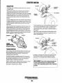
DESCRIPTION
SOLENOID
The starting system includes the battery, starter motor, solenoid,
and starter button.
When the starter button on the inslJument panel is depressed,
current flows and energizes the starter's solenoid coil. The
energized coil becomes an electromagnet, which pulls the plunger
into the coil, and closes a set of contacts which allow high current
to reach the starter motor. At the same time, the plunger also
serves to push that starter pinion to mesh with !he teeth on tile
flywheel. .
To prevent damage to tile starter motor when the engine starts, the
pinion gear incorporates an over-running (one-way) clutch which
is splined to the starter annature shaft. The rotation of the running
engine may speed the rotation of the pinion but not the starter
motor itself
Once the started button is released, the current flow ceases, stopping the activation of the solenoid. The plunger is pulled out of
contact with the battery-to-start cables by a coil spring, and the
flow of electricity is interrupted to the starter. This weakens the
magnetic fields and the starter ceases its rotation. As the solenoid
plunger is released, its movement also pulls the starter drive gear
from its engllgement with the engine flywheel.
TERMINALS·--~
~"'---(M) TERMINAL
IGNITION
TERMINAL
\
I
n
To test the ignition circuit, locate tlle ignition(s) temlinal (it is one
of the small temlinal studs and is wired to tlle ignition circuit).
Use a screwdriver, don't touch the blade, to iwnp from that
ignition terrninal to the positive battery connection terminal on
the solenoid.
If the starter cranks, the fault lies with the ignition circuit.
If the solenoid clicks but nothing else happens, the starter
motor is probably faulty.
SOLENOID
SOLENOID
MOTOR
c~rt~ifQ+- __ (+) POSITIVE
TYPICAL
TERMINAL
STARTER MOTOR
H"'--(M) TERMINAL
REFER TO THE WIRING
DIAGRAM IN THIS MANUAL
IGNITION
TERMINAL
TROUBLESHOOTING
Prior to testing, make certain the ships batteries are at full charge
and that the starting system wiring colmections (temlinals) are
clean and tight. Pay particular attention to tile growld wire
connections on the engine block.
~
If nothing at all happens the solenoid isn't getting current.
. Check tile battery isolation switch and inspect the wiring
connections. It is also possible tilat tile solenoid is defective.
To check the wiring, try cranking the starter for a few seconds,
never more than 10 seconds at a time, then run your hand along
the wires and temlinals looking for wann spots tilat indicate
resistance. Repair or replace any trouble spots.
A WARNING: There will be arching and sparks will
Using a muitimeter, test the voltage between the positive temlinal
stud on the start solenoid and the engine block (ground).
fly when jumping terminals. Be certain-the engine
space is free of potentially explosive fumes, especially
gasoline_
If you read 12 volts, the starter is faulty.
~
WESTERBEKE
Engines & Generators
19
STARTER MOTOR
SERVICE
Westerbeke uses a standard marine starter motor which can be
serviced or rebuilt at any starter motor automotive service center.
If replacing the starter motor, make certain the new motor is
certified for marine use. Automotive starters do not meet USCG
standards. If in doubt, contact your WESTERBEKE dealer.
(+) POSITIVE
____ ----)TERMINAl
~
~«i~V-""';:::---(M) TERMINAL
TO REMOVE FOR SERVICE
IGNITION
TERMINAL
1. DiscOlmect the negative battery cable.
2. If necessary, remove any components to gain full access to the
starter motor.
3. Label and disconnect the wiring from the starter. (Do not allow
wires to touch, tape over the terminals).
4, Remove tlle starter mounting bolts.
5. Remove the starter from the engine. In some cases the starter
will have to be turned to a different angle to clear obstructions.
Test again by jumping the two large tenninal studs. Hold the
screwdl1ver blade firmly between the studs. Do not allow tlle
screwdriver blade to touch the solenoid starter casing, this
would cause a short.
0,
A
WARNING: There will be arching as the full
starting current should be flowing thru the blade of the
screwdriver.
If the starter spins, the solenoid is faulty.
If the starter fails to spin, the motor is probably faulty.
If no arching occurred. There is no juice reacbing the solenoid.
NOTE: Starter motors are either inertia type or pre-engaged. In
the pre-engaged model, the solenoid also moves an arm that
engages the starter motor to theflywheel ofthe engine. Using a
screwdriver to bypass the solenoid on such a starter will run the
motor without engaging the flywheel. Turn the starter switch on to
provide the power to the solenoid. Hopefully it will create enough
magnetic field for the arm to move even though the contacts inside
the solenoid are bad.
Engine's & Generators
20
#52951
r------- ,
i
Y/' ,
i~'::
:;~ ~
"
:J
It.
I
~.
I
. ""d
r-"-"-"
I
I
I
I
I
I
i
I
I
I
""
I
I
I,
I
I
__ _
-------
I
,,,",,~WESTERBEKE
, Eng/ires & Generators
21
~~:
ii
G f§!
,"-"-:
~
,
I
1,1
?-i l!I
II
II
'---~-'
I ===~_:;=- "
I
~~! II
,
, I
L_ .. _ .. _. __ I
ENGINE TROUBLESHOOTING
The following troubleshooting table describes certain
problems relating to engine service, the probable causes of
the problems, and the recommendations to overcome these
problems.
Problem
START BUTTON depressed, no panel
indications.
Note: The engine's electrical system is protected by a 20 amp
manual reset circuit breaker located on a bracket at the rear
of the engine.
Probable Cause
Verificalion/Remedy
1. Battery Switch not on.
1. Check switch and/or battery connections.
2. Circuit breaker tripped/off.
2. Reset breaker; if breaker trips again, check preheat solenoid
5. Loose battery connections.
4. Check (+) connection to starter solenoid and (-) connection to
1. Connection to solenoid faulty.
1. Check connection.
circuit and check circuit for shorts to ground.
engine ground stud. Check battery cable connections.
START BUTTON depressed, no starter
engagement.
START BUTTON depressed; panel
indications OK; starter solenoid OK
fuel solenoid not functioning.
2. Faulty solenoid.
2. Check that 12 volts are present at the solenoid connection.
3. Loose battery connections.
3. Check battery connections.
4. Low batte ry.
5. Kl relay.
4. Check battery charge state.
5. Check Kl relay.
1. Poor connections to fuel solenoid.
1. Check connections.
2. Defective fuel solenoid.
2. Check that 12 volts are present at the (+) connection on the
fuel run solenoid.
Generator engine cranks, but does not
start, fuel solenoid energized.
Battery runs down.
1. Faulty fueling system.
1. Check that fuel valves are open.
1a. Switch to combine house and start batteries.
lb. Replace battenes.
le. Check fuel lift pump.
ld. Change inlet fuel filter.
2. Preheat solenoid faulty.
2. Check solenoid.
1. High resistance leak to ground.
1. Check wiring. Insert sensitive (0 - .25 amp) meter in battery
lines. Do not start engine. Remove connections and replace
after short is located.
2. Low resistance leak.
2. Check all wires for temperature rise to locate the fault.
3. Poor battery connections.
3. Check cable connections at battery for loose connections,
corrosion.
Battery not charging
4. DC alternator not charging,
4. Check connections, check belt tension. test alternator. See
DC ELECTRICAL SYSTEM/ALTERNATOR.
1. DC charge circuit faulty.
1. Perform D.C. voltage check of generator charging circuit. See
DC ELECTRICAL SYSTEM/ALTERNATOR in this manual.
2. Alternator drive.
2. Check drive belt tension. Alternator should tum freely. Check
for loose connections. Check output voltmeter. Ensure 12 volts
are present at the Exc. terminal.
Generator engine stops.
1. Fuel lift pump failure. er is dirty.
1. Fuel lift pump should make a distinct ticking sound. Replace.
2. Switches and/or wiring loose
2. Inspect wiring for short circuits and loose connections,
or disconnected,
Inspect switches for proper operation,
3. Fuel starvation,
3. Check fuel supply, fuel valves, Fuel filters) fuel lift pump ..
4. 20 Amp circuit breaker tripping.
4. Check for high DC amperage draw during operation.
Ensure breaker is not overly sensitive to heat which would
cause tripping.
5, Exhaust system is restricted.
5, Check for blockage or collapsed muftler.
b. Water in-fuel.
6. Pump water from fuel tank(s); change filters and
7. Air intake obstruction.
7. Check air intake_
1. Oil pressure switch.
1. Check oil pressure switch.
bleed fuel system.
Engine starts, runs and shuts down
Engine starts, runs at idle
2. Water temperature switch.
2. Check water temperature switch.
1. Electronic governor system faulty
1. Check governor system components.
I~/WESTERBEKE
.I Engines & Generators
22
(continued)
ENGINE TROUBLESHOOTING
Problem
Exhaust smoking problems
Probable Cause
Verllicatlon/Remedy
1. Blue smoke.
1. Incorrect grade of engine oil.
1a. Crankcase is overfilled with engine oil (oil is blowing out
through the exhaust).
2. Engine is running cold.
2a. Faulty injector or incorrect injector timing.
3. Improper grade of fuel.
3a. Fuel burn incomplete due to high back pressure in exhaust or
insufficient air for proper combustion (Check for restrictions in
exhaust system; check air intake.).
2. White smoke.
3. Black smoke.
LCD DISPLAYS
No LCD Display
Oil Pressure
1. Check battery.
2. 20 amp breaker off.
1. Oillevellow/oilleak.
2. Lack of oil pressure.
LED Display
Edges turn pink
3. Ground connection.
4. Faulty control module.
1. Check system coolant level.
2. Check water pump drive belt.
3. Faulty Temperature sensor.
4. Ground connection.
5. Faulty control module.
1. Check sea water flow.
2. Faulty exhaust temperature switch.
3. Ground connection.
4. Faulty control module.
5. Sea water pump.
6. Fire suppressor system.
1. Check alternator drive belt.
2. Check charge voltage.
3. Check battery connections.
4. Faulty control module.
1. Check AC voltage output.
2. Improper voltage sense connections.
3. Faulty control module.
1. Check Engine speed.
2. Check fuel supply.
3. Amperage load.
1. Compartment ambient temperature
too high.
Waiting for ECU
1. ECU or display
Coolant Temperature
Exhaust Temperature/External Fault
Battery Voltage
Generator Voltage
Generator Frequency
3b. Improperly timed injectors or valves or poor compression.
3c. Lack of air - check air intake and air filter. Check for proper
ventilation.
3d. Overload.
1. Battery on.
2. Turn breaker on.
1. Check oil level, add oil and repair leaks.
2. Test oil pressure. If OK, test oil pressure sendor, inspect oil
filter, inspect oil pump.
3 Check ground circuit.
4. Inspect all plug connections/replace.
1. Add coolant. Check for leaks.
2. Test oil pressure, replace belt.
3 Check sensor/replace.
4. Check ground circuil.
5. Check plug connections/replace.
1. Inspect thru hull fitting, hose and strainer. Correct as needed.
2. TesVreplace.
3 Check ground circuit.
4. Check plug connections.
5. Inspect impeller/replace.
6. Check systemlby-pass.
1. Adjust tenSion/replace if worn.
2. Check excitation, replace/repair alternator.
3 Check + and· cables from battery to engine.
4. Check plug connections/replace.
1. Adjust voltageltroubleshoot generator for cause.
2. Check connections.
3 Check plug connections/replace.
1. Adjust.
2. Inspect filters/replace filters. Test fuel pump operation.
3 Check load with amprobe.
1. Ventilate compartment.
Note: Heat will often change the color of an ICD displar
This will nat effect the operation of the engine.
1. Check compatibility of ECU/display lor
NEMA 2000 or Westlink.
Engines & Generators
23
ALTERNATORS TESTING/TROUBLESHOOTING
'10 ORANGE B
TO STARTER SOLENOID
60 AMP ALTERNATOR
EXCITER
TERMINAL
R
ALTERNATOR TROUBLESHOOTING
#16 VIOLETR
TO K-3 RELAY .
'16 RED TO
ACTUATOR
VOLTAGE REGULATOR
The integral voltage regulator is an electronic switching
device which senses the system voltage level and switches
Ibe voltage applied to Ibe field in order to maintain a proper
system voltage.
The regulator design utilizes all-silicon semi conductors and
thick-film assembly techniques. After Ibe voltage has been
adjusted to the proper regulating valve, Ibe entire circuit is
encapsulated to protect Ibe circuit and the components from
possible damage due to handling or vibration.
REFER TO THE WIRING
DIAGRAM IN THIS
MANUAL FOR ALL
WIRING CONNECTIONS
Use this troubleshooting section to deterntine if a problem
exists wilb Ibe charging circuit or with the alternator. If it is
deterntined that the alternator or voltage regulator is faulty,
have a qualified technician check it.
DESCRIPTION
A WARNING: A working alternator runs hot. A failed
The following iofonnation applies to Ibe standard alternato~
Ibat are supplied wilb WES1ERBEKE'S Engines and
Generators.
ELECTRICAL CHARGING CIRCUIT
The charging system consists of an alternator wilb a voltage
regulator, an engine DC wiring hamess, a mounted DC
circuit breaker and a battery wilb connecting cables. Because
of Ibe ose of integrated circuits (IC's), Ibe electronic voltage
regulator is very compact and is mounted internally or on the
back of the alternator.
It is desirable to test Ibe charging system (alternator and
voltage regulator) using the wiring hamess and electrical
loads that are a pennanent part of Ibe system and williben
provide the technician with an operational test of the
charging system as well as the major components of Ibe
electrical system.
ALTERNATOR OESCRIPTION
The stator is connected to a three-phase, full-wave bridge
rectifier package which contains six diodes. The bridge
converts the AC generated in the stator to a DC output for
battery charging and accessories,
Power to the regulator and Ibe field of the integral regulator
alternator is provided by the field diode (or diode trio)
package contained in the alternator.
These alternators produce a rated output of 60 amps. Rated
output is achieved at approximately 6000 alternator rpm at
an ambient temperature of 75°P (23.8°<::). The alternators
are designed to operate in an ambient temperature range
of -40° to 212°P (-40° to !OO°C).
alternator can become very hot. Do not touch the
alternator until if has cooled.
LOW BATTERY/FAULTY CIRCUIT
If Ibe starter only moans or makes a clicking sound instead
of spinning Ibe engine to life it is likely a low battery or a
faulty connection in Ibe starting circuit and not an alternator
problem.
PRELIMINARY INSPECTION
Before starting the actual alternator and voltage regulator,
testing the following checks are recommended.
1. Make certain your alternator is securely mounted.
2. Check Ibe drive belts for proper tension. Replace Ibe belt
if it is worn or glazed.
3. Check that all tenninals, connectors and plugs are clean
and tight. Loose or corroded connections cause high
resistance and this could cause overcharging,
undercharging or damage to the charging system. Badly
corroded battery cables could prevent the battery from
reaching a fully charged condition.
4. Check Ibe condition of Ibe battery and charge if necessary.
A low or discharged battery may cause false or misleading
readings in Ibe tests.
NOTE: An isolator with a diode, a solenoid, or a battery
selector switch is usually mounted in the circuit to isolate
the batteries so the starting battery is not discharged along
with the house batteries. If the isolator is charging the
starting battery but not the house battery, the alternator is
OK and the problem is in the battery charging circuit.
Engines & Generators
24
ALTERNATORS TESTING/TROUBLESHOOTING
MEASURING
BATTERY VOLTAGE
TESTING THE ALTERNATOR
(IGNITION ON
ENGINE
A CAUTION: Before starting the engine make
certain that everyone is clear of moving parts! Keep
away from sheaves and belts during test procedures.
1. Start the Engine.
2. After the engine has run for a few minutes, measure the
starting battery voltage at the battery termin'lls using a
multimeter set on DC volts.
a. If the voltage is increasing toward 14 volts, the
alternator is working.
b.If the voltage remains around 12 volts, a problem
exists with either the alternator or the charging circuit;
continue with Steps 3 through 6.
TESTING THE OUTPUT CIRCUIT
MEASURING
BATTERY VOLTAGE
1. Connect the positive probe to the output terminal Band
connect the negative probe to ground.
(ENGINE RUNNING)
2. Wiggle the engine wiring harness while observing the
voltmeter. The meter should indicate the approximate
battery voltage, and should not vary. If no reading is
obtained, or if the reading varies, check the alternator
output circuit for loose or dirty connections or
damaged wiring.
3. Start the engine.
4. Repeat the same measurement, the negative probe to
ground, the positive probe to B with the engine running.
The voltage reading should be between 13.5 and 14.5
volts. If your alternator is over or under-charging, have
it repaired at a reliable service shop.
S. If the previous test reads only battery voltage at
terminal B, use the meter to measure the DC excitation
terminal. If 12 volts is not present at exciter terminal R,
inspect the wiring for breaks and poor connections.
Jump 12 volts from a 12 volt source (such as the
battery) and operate the alternator. If the voltage output
is 13-14 volts, .. then the alternator is OK.
3. 111m otT the engine. Inspect all wiring and connections.
Ensure that the battery terminals and the engine ground
connections are tight and clean
4. If a battery selector switch is in the charging circuit,ensure
that it is on the correct setting.
S. 111m on the ignition switch, but do not start the
engine.
6. Check the battery voltage. If your battery is in good
condition the reading should be 12 to 13 volts.
.TERNIINALR
TESTING THE OUTPUT
CIRCUIT ENGINE RUNNING
#10 ORANGE B
TO STARTER ~UU'NOIU-f~~~1!
Engines & Generators
25
#16 VIOLET R
TO K·3 RELAY
#16 REO TO
ACTUATOR
ALTERNATORS TESTING/TROUBLESHOOTING
TESTING THE EXCITATION CIRCUIT
CHECKING THE SERVICE BATTERY
1. Connect the positive (+) multimeter probe to the
excitation terminal R on the alternator and the negative
H lead to ground.
2. 10m the ignition switch to the on position and note
the multimeter reading. The reading should be 1.3 to
2.5 volts (see illustration).
OUTPUT TERMINAL
Check the voltage of the service battery. this battery should
have a voltage between 13 and 14 volts when the engine is
running. If not, there is a problem in the service battery
charging circuit. Troubleshoot the service battery charging
circuit by checking the wiring and connections, the solenoid,
isolator, battery switch, and the battery itself.
When the problem has been solved and before the alternator
is back in operation, take the time to tighten and clean the
terminal studs. Also clean the connecting terminals from the
wiring harness.
TESTING THE
EXCITATION
CIRCUIT
EXCITER
TERMINAL
(ENGINE'
RUNNING)
ALTERNATOR REPAIR
If tests indicate a failed alternator, it will need to be disassembled and repaired. Any good alternator service shop can
do the job.
NOTE: WESTERBEKE'S Service Manual has detailed
instructions for the disassembly and repair a/their
standard altemators.
BATTERY CARE
The minimum recommended capacity of the battery used in
the engine's 12 volt DC control circuit is 800-1000 Cold
Cranking Amps (CCA).
Review the manufacturer's reconunendations and then
establish a systematic maintenance schedule for your
engine's starting batteries and house batteries.
• Monitor your voltmeter for proper charging during
3. If the reading is between. 75 and 1.1 Yolts, the
rotor field circuit probably is shorted or grounded.
4. If the reading is between 6.0 and 7.0 Yolts, the rotor
field circuit probably is open.
S. If no reading is obtained, an open exists in the
alternator-excitation lead or in the excitation circuit of
the regulator. Disconnect the lead from exc terminal R.
Connect the positive multimeter probe to the excitation
lead and the negative multimeter probe to ground.
If the multimeter now indicates an approximate battery
voltage, the voltage regulator is defective and must be
replaced. If no voltage is indicated, check the
excitation circuit for loose or dirty connections or
damaged wiring.
engine operation.
•
•
•
Check the electrolyte level and specific gravity with a
hydrometer.
Use only distilled water to bring electrolytes to a proper
level.
Make certain that battery cable connections are clean and
tight to the battery posts (and to your engine).
OUTPUT TERMINAL
TESTING THE
EXCITATION
CIRCUIT
ENGINE
RUNNING
EXCITER
TERMINAL
R
REMOVE FROM
TERMINALR
"
Engines & Generators
26
GLOW PLUGS
DESCRIPTION
Re-install the plugs in the engine and test them again. The
plugs should get very hot (at the terminal end) within 7 to 15
seconds. If the plugs don't heat up quickly, check for a short
circuit. When reinstalling the glow plugs, use anti-seize
compound on the threads.
The glow plugs are wired through the preheat solenoid.
When PREHEAT is pressed at the control panel this solenoid
should "click" on and the glow plug should begin to get hot.
INSPECTION
A WARNING: 00 not keep a glow plug on for more
To inspect the plug, remove the eleclrical terminal connections, then unscrew or unclamp each plug from the cylinder
head. Thoroughly clean each plug's tip and threads with a
soft brush and cleaning solution to remove all the carbon and
oil deposits. While cleaning, examine the tip for wear and
bum erosion; if it has eroded too much, replace the plug.
than 30 seconds.
GLOW PLUG TIGHTENING TORQUE
1.0 - 1.5 M-KG (7 -11 FHB)
.6'===<===-=:~ TERMINAL END
TESTING
An accurate way to test glow plugs is with an ohmmeter.
Touch one prod to the glow plug's wire connection, and the
other to the body of the glow plug, as shown. A good glow
plug will have a 1.0 - 1.5 ohm resistance. Ibis method can be
used with the plug in or out of the engine. You can also use
ao multimeter to test the power drain (8 - 9 amps per plug).
TESTING WITH
AN OHMMETER
KEYI'PREI~EAT ON
A WARNING: These glow plugs will become very hot
TIP
to the touch. Be careful not to burn your fingers when
testing the plugs.
USING A
TEST LIGHT
GLOW PLUGS
REFER TO THE WIRING
DIAGRAM IN THIS
MANUAL FOR ALL
WIRING CONNECTIONS
+
Engines & Generators
27
ENGINE ADJUSTMENTS
NOTE: WESTERBEKE recommends that the following engine adjustments be peiformed by a competent engine mechanic. The information
below is provided to assist the mechanic.
ENGINE COMPRESSION
Check the compression pressure. To do this wann the engine,
remove all fuel injectors, or glow plugs, disconnect the fuel
"~Shut_Off solenoid wire, and install a compression adapter in
'''-.,.
the injector hole or glow plug hole. Connect a compression
"-.,.
tester on the adapter and crank the engine with the starter
'Jif:ffI'~~
motor until the pressure reaches a maximum value. Repeat
this process for each cylinder. Look for cylinders with
Idnumltic,ally (at least 20%) lower compression than the
,m'enlge of the others. Compression pressure should not differ
by more than 35.5 psi (2.5 kg/cm') at 280 rpm.
If a weak cylinder is flanked by healthy cylinder, the problem
OIL PRESSURE GAUGE
is either valve or piston related. Check the valve clearances
for the weak cylinder, adjust as needed and test again. If the
cylinder is still low, apply a small amount of oil into the
TESTING OIL PRESSURE
cylinder to seal the rings and repeat the test. If compression
To tesJ the oil pressure,_l'effiove the oil pressure sender, then
comes up - the rings are faulty.
install a mechanical oil pressure gauge in it's place. After
Abnormally high readings on all cylinders indicates heavy
wanning up .the engine, set the engine speed at idle and read
carbon accumulations, a condition that might be
the oil pressure gauge.
accompanied by high pressures and noise.
OIL PRESSURE WILL RANGE BETWEEN 50 AND 55PSI AT 1800 RPM
PLUG
.
NOTE: In case of severe vibrations and detonation noise, the
cause may be fuel injector problems, see FUEL
INJECTORS. Poor fuel quality, contaminates and loss of
positive fuel pressure to the injection pump will result in
injector faults.
LOW OIL PRESSURE
The specific safe minimum oil pressure is 5 - 10 psi. A gradualloss of oil pressure usually indicates worn bearings. For
additional information on low oil pressure readings, see the
ENGINE TROUBLESHOOTING charlo
When re-installing the glow plugs use anti-seize compound.
VALVE ADJUSTMENT
Remoye the glow plugs from the cylinder so the engine can
be easily manu3Uy rotated. Remove the valve train rocker
cover. Rotate the engine crank manually and observe the
valve operatidnfor cylinder #1 and bring the #1 piston up to
Top Dead Center of the compression stroke. Adjust the valves
referencing the charl below. Rotate the crankshaft 360'. This
should put the valves for cylinder #1 in the overlap position.
Adjust the remaining valves following the ch;ut below.
COMPRESSION TESTER
ADAPTER",
VALVE CLEARANCE (ENGINE COLD) 0.23 - 0.27mm (0.0091 • 0.0106 in)
When No.1
piston is
compressed
Top Dead
Center
When No.1
piston is in
overlap
position
1st
2nd
3rd
4th
1st
2nd
3rd
4th
IN
0
0
0
IN
0
EX
0
0
IN
0
0
0
~
TESTING ENGINE
COMPRESSION
0
0
0
I VALVE CLEARANCE
--'L
~
i!iIl I·
(ENGINE COLD)
0.23 - 0.27mm
(0.0091 - 0.0106 in)
,.yo
",:>;..,+~;./:.
~~~INJECTOROR
0
0
0
~
EX
0
0
0
.'::~~~
it:
EX
"
WESTERBEKE
Engines & Generators
28
GLOW PLUG HOLE
ENGINE ADJUSTMENTS
DRIVE BELT ADJUSTMENT
NOTE: Clean the area around the base of the injector
prior to lifting it out of the cylinder head to help prevent
any rust or debris from falling down into the injector
hole. If the injector will not lift out easily and is held in
by carbon build up or the like, work the injector side to
side with the aid of the 17mm deep socket wrench to free
it and then lift it out.
For your safety, WESTERBEKE generator models come
equipped with belt guards that cover over the belt(s) on the
front of the engine. ("Out of sight - out of mind." The belt
guard is NOT installed for that purpose.) Operators are
advised that proper inspection, service, and maintenance is
required.
The drive belt must be properly tensioned. Excessive drive
belt tension can cause rapid wear of the belt and reduce the
service life of the fresh water pump's bearing. A slack belt or
the presence of oil on the belt can cause belt slipping,
resulting in high operating temperatures.
3.
The injector seats in the cylinder head on a copper sealing washer. This washer should be removed with the
injector and replaced with a new washer when the injector is reinstalled.
The generator have two drive belts, one drives the governor
and alternator and the other drives the raw water pump. The
tension adjustment procedure for both belts is as follows:
1. Using the nozzle tester, check the spray pattern and injection starting pressure of nozzle and, if it exceeds the
limit, adjust or replace the nozzle. When using nozzle
tester, take the following precautions:
INJECTION TESTING
L Remove the belt guard.
2. Loosen the alternator adjusting strap bolt and the base
. mounting bolt.
A
CAUTION: The spray Injected from the nozzle Is
of such velocity that It may penetrate deeply Into the
skin of fingelS and hands, destroying tissue. If It
entelS the bloodstream, It may cause blood pOisoning.
3. With the belt loose, inspect· for wear, cracks and frayed
edges.
4_ Pivot the alternator on the base mounting bolt to the left
or right as required, to loosen or tighten.
INJECTION PRESSURE TEST
5. The drive belts are properly adjusted if it can be deflected
no less than 3/8 inch (lOmm) and no more than l!2 inch
(l2mm) as the belt is depressed with the thumb at the
. midpoint between the two pulleys on the longest span of
the belt.
INJECTION PRESSURE
140 ·150 Kgl/cm'
(1991·2133 PSI)
A WARNING: Never attempt to check or adjust a
drive ben's tension while the engine is in operation.
Inspecting Spray Pattern
6. Operate the generator for about 5 minutes, then shut down
the generator and recheck the belts) tension.
7. Replace the belt guard.
FUEL INJECTORS
NOTE: WESTERBEKE recommends that the following engine adjustments
1. Operate the hand lever of the nozzle tester at intervals of
one stroke per second to check if the fuel is injected correctly in its axial direction. A nozzle is defective if it
injects fuel in an oblique direction or inseveral separate
strips. Also, a spray in the form of particles indicates a
defect. These defects may sometimes be caused by clogging with dust and, therefore, all parts should he carefully
cleaned before reassembly.
be performed by a competent engine mechanic. The injonnation below is
provided to assist the mechanic.
DRIPTEST
~
REMOVING THE INJECTORS
NORMAL
,.d
rIllE: Injector must be serviced in a "clean room" e1Wironment.
1. Disconnect the high pressure lines from the injectors and
loosen the lines at their attachment to the injection pump
and move them out of the way of the injectors. Avoid
bending the lines.
2 Using a 17mm long socket, remove the fuel return line in
its entirety from the top of the injectors. Take care not to
lose the two sealing washers and banjo bolt that attaches
the fuel return line to each injector.
llilOO
],
~ FAUlTY
V,,if
~
..
'" FAULTY
','
~t
2. Apply the pressure of 1635 lb/in' (115 kg/cm') to nozzle
by operating the hand lever, and check the drips from the
nozzle tip. If it drips or has a large accumulation of fuel
on the bottom, it is considered defective and should be
replaced. A very small amount of fuel may sometimes
remain on the tip of the nozzle; however, this does not
indicate a defect.
CHATTERING TEST
kiI dI @
omp TEST
Engines & Genera,tors
29
>.,,.
ENGINE ADJUSTMENTS
TESTING THE MAGNETIC PICK UP COIL
MAGNETIC PICK·UP [MPUjINSTALLATION
Test the speed sensor connector for voltage and resistance
values.
If the values are correct, remove and inspect the magnetic
pick up. With the wires disconnected, unscrew the
magnetic pick up from the generator housing and visually
inspect the contact end. If any damage is detected, replace
the unit.
NOTE: Carefully follow the installation instructions
The MPU is installed in the threaded opening on the side
of the flywheel bellhousing. This positions the MPU over
the teeth of the flywheel ring gear.
Viewing through this opening, manually rotate the engine
crankshaft so as to position the flat of one of the ring
gear's teeth directly under the opening. Thread the MPU
into the opening until it gently contacts the flat of this'
tooth (Thread is 3/8" x 24). Back the MPU out of the
opening one tum and then lock it in this position with
the jam nut. This will position the end of the MPU
approximately 0.030 inches away'from the flats of the
ring gear teeth.
To ensure the MPU is positioned correctly, slowly rotate
the crankshaft by 360' by hand to assure there is no
physical contact between the MPU and the ring gear teeth.
If contact is felt between the MPU and the flywheel teeth,
the MPU may be damaged. Remove the MPU and inspect
it. Replace if necessary and repeat the above
installation procedure.
NOTE: When replacing the Magnetic Pick-Up (MPU) it
MUST be replaced without cutting and splicing into the
existing wiring cable. Doing so will cause a erratic AC
signal to the controller.
provided with the new magnetic pick up coil.
SPEED SENSOR TEST VALUES
VOLTAGE (while cranking)
1.5 - 2.5 VAC
RESISTANCE (at rest)
950 - 1000 ohm
~
K-UP~
~~,"?'~(:::' MPU-MAGNETtC PIC~
~'
~0.030tn
--
Engines & Generators
30
SPECIFICATIONS
25.5/23.5KW, 28.5/23.5KW, 33.0.26.0KW EDE
ENGINE SPECIFICATIONS
Engine Type
COOLING SYSTEM
Diesel, four-cycle, fouf-cylinder, fresh
General
Fresh water-cooled engine block,
thermostatically-controlled with heat exchanger.
Operating Temperature
160 -180° F (71 - 82° C)
Fresh Water Pump
Centrifugal type, metal impeller, belt-doven
Raw Water Pump
Positive displacement, rubber impeller,
gear-driven.
System Capacity
(fresh water)
16 qts (15.1Itters)
Raw Water Flow Rate
(at 1800 rpm)
11.0 gpm (41.6Ipm)
water-cooled, vertical in-line overhead valve
mechanism.
Aspiration
Naturally aspirated
Compression Ratio
21.8:1
Governor
Electronic
Combustion Chamber
Swirl type
Bore & Stroke
98 x 110 mms (3.86 x 4.93 iinches)
Piston Displacement
3.31 Itters (202.53 cubic inches)
Hp@1800rpm
55
Hp@ 1500rpm
48
Rong Order
1-3-4-2
General
Open flow, seH bleeding, self priming
(electromagnetic fuel pump)
Inclination
Continuous 20°
Temporary 30° (not to exceed 10 min.)
Fuel
No.2 diesel (cetane rating of 45 or higher)
Weight (dry)
11351bs (514.8 kgs)
Fuel Injection Pump
Bosch type mini-pump
Fuel Injection Timing
r BTDC (spill)
FUEL SYSTEM
TUNE-UP SPECIFICATIONS
Compression Pressure
(allowable limtt)
626 psi (44 kgf/cm') at 250 rpm
472 psi (30.5 kgf/cm') at 250 rpm
Variation between
cylinders
10% or less
Injection Timing
rBTDC
Engine Speed
1800 rpm 60 Hertz
1500 rpm 50 Hertz
Injector Nozzle
Bosch throttle type
Fuel Filter
Spin-on type
Air Intake
Metal screenlintake silencer box
Air Flow Combustion
105 ctm (3.0 cmm)
LUBRICATION SYSTEM
General
Pressure fed system with external relief valve
Oil Filter
Full flow, paper element, spin-on type
Valve Clearance
(engine cold)
0.23 to 0.27 mm
(0.00091 to 0.0106 inches)
1991 to 2134 psi (140 to 150 kgf/cm')
Sump Capacity
(includes oil filter)
14.0 U.S. qts (13.2Itters)
Injector Pressure
Valve Timing
Intake Opens W BTDC
Intake Closes 36° ABDC
Operating Oil Pressure
(engine hot)
28 - 57 psi (2.0 - 4.0 kg/em')
Exhaust Opens 45° BBDC
Exhaust Closes 1r ATDC
Oil Grade
API Specification CF, CG-4, Cf-4 or CH-4
SAE 10W-30, 15W-40
GENERATOR COOLING
ELECTRICAL SYSTEM
Starting Battery
12-Voli DC (-) negative ground
Battery CapacITy
800-1000 CCA
DC Charging Aliemator
60 Amp rated, belt-doven
Starter
2.5Kw, 12VDC direct dove
Starting Aid
Glow plugs, sheathed type
DC Cran~ng Current
400 - 600 (includes glow plugs)
Air Requirements
(generator cooling)
0.8 Power factor untt. 500 CFM (15.0 CMM)
NOTE: Increase cooling air flow 15% for slower tuming 50hz units.
Generator Compartment
Ambient Temperature
~
WESTERBEKE
Engines & Generators
31
122° F(50° C) maximum
SPECIFICATIONS 25.5/21.0KW EDE
AC GENERATOR (Single Phase)
Single Phase
AC GENERATOR (3 Phase)
Brushless, six- pole, revolving field.
Sealed lubricated, single-bearing design. 12
Lead reconnectable (Double Delta for 1201240
volts, 60hz.) (Series Star for 230 volts, 50hz)
With solid state voltage regulator.
Vottage
120 or 1201240 votts - 60 hertz
230 Volts - 50 Hertz
Vottage Regu~tion
± 2% no load to full load.
Frequency Regulation
.3 Hertz (.5%) no load to full load.
Rating (Vans AC)
60 Hz (1800 rpm)
12.5 KW
120 volts
1201240 volts
212.5 amps
212.5/106.3 amps
50 Hz (1500 rpm)
230 volts
91.3 amps
9.3KW
Generator Cooling
400 cfm (11.3 cmm)
Three Phase
Brushless, six'pole, revolving field. Sealed
lubricated, single-bearing design. 12 Lead
reconnectable. Solid state voltage regulator.
Voltage - 3 phase
(60 Hertz)
Low Vottage WYE
High Voltage WYE
DELTA
240 Volts
480 Volts
277 Volts
Voltage' 3 Phase
(50 Hertz)
High Voltage WYE
DELTA
400 Volts
230 Volts
Amperage· 3 phase
(60 Hertz)
Low Vottage WYE
High Voltage WYE
DElTA
76 Amps
38 Amps
66.5 Amps
Amperage - 3 phase
(50 Hertz)
High Voltage WYE
DELTA
37.9 Amps
65.9 Amps
Generator Cooling
Air requirements
(60 Hz) at 1800 rpm
225 - 250 cfm (5.66 . 6.37 cmm)
Air requirements
(Single & 3 phase)
NOTE: Increase air supply 15% for 50 Hertz
operation (1500 rpm)
NOTE: Increase air supplY 15% for 50 Heltz
Generator Compartment
Ambient Temperature
Recommendations
operation (1500 rpm)
Generator Compartment
Ambient Temperature
122'F (50'C) maximum
Recommendations
NOTE: Forced venlilation should be provided
122'F (50'C) maximum
NOTE: Forced venlilation should be provided
to maintain generator compartment
temperatures below 104'F (40'C).
to maintain generator compartment
temperatures below 104'F (40'C).
SPECIFICATIONS 28.5/23.5KW EDE
AC GENERATOR (Single Phase)
Single Phase
Brushless, six- pole, revol~ng field.
Sealed lubricated, Single-bearing design. 12
Lead reconnectable (Double Delta for 1201240
votts, 60hz.) (Series Star for 230 volts, 50hz)
With solid state vottage regulator.
Vottage
120 or 1201240 volts· 60 hertz
230 Volts - 50 Hertz
Vottage Regulation
± 2% no load to full load.
Frequency Regulation
.3 Hertz (.5%) no load to full load.
Rating (Vans AC)
60 Hz (1800 rpm)
50 Hz (1500 rpm)
Generator Cooling
Air requirements
(Single & 3 phase)
AC GENERATOR (3 Phase)
120 votts
120/240 volts
237.5 amps
237.5/f 18.8 amps
230 volts
102.2 amps
400 cfm (11.3 cmm)
Brushless, six'pole, revolving field. Sealed
lubricated, single-bearing design. 12 Lead
reconnectable. Solid state vottage regulalor.
Voltage - 3 phase
(60 Hertz)
Low Vottage WYE
High Voltage WYE
DElTA
240 Volts
480 Volts
277 Volts
Voltage' 3 Phase
(50 Hertz)
High Voltage WYE
DELTA
400 Volts
230 Volts
Amperage - 3 phase
(60 Hertz)
Low Vottage WYE
High V~tage WYE
DELTA
85.8 Amps
42.9 Amps
74.3 Amps
Amperage· 3 phase
(50 Hertz)
High Voltage ,WYE
DElTA
42.4 Amps
73.8 Amps
Generator Cooling
Air requirements
(60 Hz) at 1800 rpm
225 - 250 cfm (5.66 - 6.37 cmm)
NOTE: Increase air supplY 15% lor 50 Heltz
operation (1500 rpm)
NOTE: Increase air supPlY 15% lor50 Heltz
Generator Compartment
Ambient Temperature
Recommendations
operation (1500 rpm)
Generator Compartment
Ambient Temperature
Recommendations
Three Phase
122'F (50'C) maximum
122'F (50'C) maximum
NOTE: Forced ventilation should be provided
to maintain generator compattment
NOTE: Forced ventilation should be provided
temperatures below 104'F (40'C).
to maintain generator compattment
temperatures below 104'F (40'C).
~
WESTERBEKE
Engines & Generators
32
SPECIFICATIONS 33.0/26.0KW EDE
AC GENERATOR (Single Phase)
Single Phase
Brushless, six- pole, revolving field.
Sealed lubricated, single-bearing design. 12
Lead reconnectable (Double Delta tor 1201240
voHs, 60hz.) (Series Star tor 230 volts, 50hz)
Wfih solid state voltage regulator.
Voltage
120 or 1201240 volts - 60 hertz
230 Volts - 50 Hertz
Voltage Regulation
±2% no load to tuilioad.
Frequency Regulation
.3 Hertz (.5%) no load to tuilioad.
Rating (Volts AC)
&0 Hz 11800 rpm)
50 Hz 115011 rpm)
Generator Cooling
Air requirements
(Single & 3 phase)
AC GENERATOR (3 Phase)
120 volts
120/240 volts
275 amps
275/137.5 amps
230 voHs
113 amps
500 cfm (14.1 cmm)
Three Phase
Brushless, six-pole, revolving freld. Sealed
lubricated, single-bearing design. 12 Lead
reconnectable. Solid state voltage regulator.
Voltage - 3 phase
(60 Hertz)
Low Voltage WYE
High Voltage WYE
DELTA
240 Volts
480 Volts
277 Volts
Voltage - 3 Phase
(50 Hertz)
High Voltage WYE
DELTA
400 Volts
230 Volts
Amperage - 3 phase
(60 Hertz)
Low Voltage WYE
High Voltage WYE
DELTA
99.3 Amps
49.6 Amps
86.0 Amps
Amperage - 3 phase
(50 Hertz)
High Voltage WYE
DELTA
46.9 Amps
81.6 Amps
Generator Cooling
Air requirements
(60 Hz) at 1800 rpm
225 - 250 ctm (5.66 - 6.37 cmm)
NOTE: Increase air supply 15% for 50 Hertz
operation (1500 rpm)
NOTE: Increase air supply 15% for 50 Hertz
Generator Compartment
Ambient Temperature
Recommendations
operation (1500 rpm)
Generator Compartment
Ambient Temperature
122'F (50'C) maximum
Recommendations
NOTE: Forced ventilation should be provided
122'F (50'C) maximum
NOTE: Forced ventilation should be provided
to maintain generator compartment
lemperatures below 104'F (40'C).
to maintain generator compartment
temperatures below 104'F (40'C).
""'" WESTERBEKE
Engines & Generators
32A
GENERATOR INFORMATION
USE OF ELECTRIC MOTORS
Generator Frequency Adjustment
The power required to start an electric motor is considerably
more than is required to keep it running after it is started.
Some motors require much more current to start them than
others. Split-phase CAC) motors require more current to start,
under similar circumstances, than other types. They are commonly used on easy-starting loads, such as washing
machines, or where loads are applied after the motor is
started; such as small power tools. Because they require 5 to
7 times as much current to start as to run, their use should be
avoided, whenever possible, if the electric motor is to be driven by a small generator. Capacitor and repulsion-induction
motors require from 2 to 4 times as much current to start as
to run. The current required to start any motor varies with the
load connected to it. An electric motor connected to an air
compressor, for example, will require more current than a
motor to which no load is connected.
In general, the current required 10 start 115-Volt molOrs connected
10 medium s1ID1ing loads will be approximately as follows:
Frequency is a direct result of engine/generator speed, as indicated by the following:
o When the generator is run at 1800 RPM, the AC voltage
output frequency is 60 Hertz.
Therefore, to change the generator's frequency, the generator's
drive engine's speed must be changed .a1ong with a reconfiguring of the AC output connections at the generator.
MOTOR SIZE
(HP)
1/6
1/4
1/3
1/2
3/4
1
AMPS FOR
RUNNING
(AMPEREi»
3.2
4.6
5.2
7.2
10.2
13
Generator Maintenance
o
Maintaining reasonable cleanliness is important.
Connections of tenninal boards and rectifiers may become
corroded, and insulation surfaces may start conducting if
salts, dust, engine exhaust, carbon, etc. are allowed to
build up. Clogged ventilation openings may cause excessive heating and reduced life of windings.
o For unusually severe conditions, thin rust-inhibiting
petroleum-base coatings, should be sprayed or brushed
over all surfaces to reduce rusting and con:osion.
In addition to periodic cleaning, the generator should be
inspected for tightness of all connections, evidence of
overheated tenninals and loose or damaged wires.
The drive discs on single bearing generators should be
checked periodically if possible for tightness of screws and
for any evidence of incipient cracking failure. Discs should
not be allowed to become rusty because rust may
accelerate cracking. The bolts which fasten the drive disc
to the generator shaft must be hardened steel SAE grade 8,
identified by 6 radial marl<s, one at each of the 6 comers of
the head.
o The rear armature bearing is lubricated and sealed; no
m...intenance is required. However, if the bearing becomes
noisy or rough-sounding, have it replaced.
Examine bearing at periodic intervals. No side movement
of shaft should be detected when force is applied. If side
motion is detectable, inspect the bearing and shaft for
wear. Repair must be made quickly or major components
will rub and cause major damage to generator.
AMPS FOR
o
(7TARTIN~)
AMPERES
6.4 to 22.4'
9.2 to 32.2'
10.4 to 72.S'
14.4 to 29.2'
20.4 to 40.S'
26 to 52
o
'NOTE: In the above table the maximum Amps for Starting is
more for some small motors than fa r larger ones. The reason
for this is that the hardest starting types (split-phase) are not
made in larger sizes.
Because the heavy surge of current needed for starting
motors is required for only an instant, the generator will not
be damaged if it can bring the motor up to speed in a few
seconds. If difficulty is experienced in starting motors, tum
off all other electrical loads and, if possible, reduce the load
o
on the electric motoT.
Required Operating Speed
Run the generator first with no load applied, then at half the
generator's capacity, and finally loaded to its full capacity as
indicted on the generator's data plate. The output voltage
should be checked periodically to ensure proper operation of
the generating plant and the appliances it supplies. If an AC
voltmeter or ampmeter is not installed to monitor voltage and
load, check it with a portable meter and amp probe.
~
Carbon Monoxide Detector
WESTERBEKE recommends mounting a carbon
monoxide detector in the vesssel's living quarters. Carbon
Monoxide, even in small amounts, is deadly.
The presence of carbon monoxide indicates an exhaust leak
from the engine or g~nerator or from the exhaust elbow/
exhaust hose, or tllat fumes from a nearby vessel are
entering your boat.
If carbon monoxide is present, ventilate tlle area with clean
air and correct the problem ilIDllediately!
WESTERBEKE
Engines & Generators
33
TWELVE LEAD WINDING/TERMINAL BOARD CONNECTIONS
AND (NOMINAL) VOLTAGES
. (SERIES WYE)
1
SERIES
STAR
2
3
L
(pARALLEL WYE)
11 3
PARAllEL
STAR
N
L
L
SERIES
DElTA
N
4
9
5
10-'11
2-3
o
0
5
6-7
L
L
L
ru
10-12
2-4
6-8
1-3
5-7
(
9t
L2
L3
9
0
T
L1
N
50 Hz L-L 400 volts
50 Hz L-N 230 volts
60 Hz L-L.480 volts
60 Hz L-N 277 volts
6
L
5
t
213
0
6-7
0
1~12
5-4
9-8
L1
L2
10-11
0
N
THREE PHASE
ZIG·ZAG
11 N
~.
Q
L
N
10-12
2-4
o
0'
9 11
_L
10r3;:'5
7
6-8
1.3
L\.,~2
SINGLE PHASE
PARALLEL ZIG-ZAG
L
o
50 Hz L-L 230 volts
50 Hz L-N 115 volts
60 Hz L-L 277 volts
60 Hz L-N 138 volts
(Refer to Note # I)
50 Hz L-L 200 volts
50 Hz L-N 115 volts
60 Hz L-L 240 volts
60 Hz L-N 138 volts
PARALLEL
DELTA
0
(
L
L
7
I
4-8-12
o
L3
L1
L
8
1 3
()
5 7
L .9
6-9
~
8-10
0
.:11
2-12
0
0
,
~
5
Q
4-6
3-7-11
0
rD
0
I
L2
L1
L3
N 1.1
50 Hz L-L 115 volts
60 Hz L-L 138 volts
7
10
1
4
L2
l1
L3
60 Hz L-L 415 volts
60 Hz L-N 240 volts
(Refer to Note #2)
DOUBLE
DELTA
L
2-WIRE
8-11
0
1 10
~2
2-3
5 12
N
6-9
0
7 4
L1
Nole #1 Single phase ampemge load,
0
N
50 Hz L-L 346 volts
50 Hz L-N 200 volts
50 Hz L-L 230 volts
50 Hz L-N 115 volts
60 Hz L-L 277 volts
60 Hz L-N 138 volts
(Refer to Note #1)
DOUBLE
DELTA
L
L2
The phase cun-ent must not exceed the
nominal value.
Note #2 17l1"ee phase zig-zag connection.
The rated pOlver must be multiplied by
0,866,
10
7
L
8-11
0
(
1 10
50 Hz L-L 230 volts
50 Hz L-N 115 volts
60 Hz L-L 240 volts
60 Hz L-N 120 volts
L
4
N
2-3
6-9
5 12
7 )4
~
0
L1
50 Hz L-N 230 volts
60 Hz L-N 240 volts
Engines & Generators
34
0
CHANGING HERTZ AND VOLTAGE
3. 111ere are Ull'ee line connections. When an L3 is not
present on the AC tenninal block, insulate and tie off
the L3 connection from tl1e Voltage Sensing Board.
4. Inside the control box, locate the ECU and position the
HertzlFrequency dip switch in the correct position for the
HertzlFrequency desired.
S. Verify all connections are correct and turn off any AC
panel breakers;
6. Start the generator and monitor the AC output voltage at
the generator's tenninal board. Line to line, line to neutral.
Adjust the voltage regulator board as needea to obtain the
correct voltage. Check the generator hertzlfrequency with
your hertz meter.
7. Turn on the AC panel breakers and load unit and monitor
the operation.
A
CAUTION: As a precaution against an
unintentional start, shut off the 20 Amp DC breaker
on the control panel.
1. Refer to the previous page that illustrates the various AC
voltage output configurations for both the 60 Hertz and
50 Hertz applications. Select the configuration for the
HertziVoltage required.
2. Reconfigure the 12 AC connections on the tenninal
board carefully following the illustration. Reference
below the voltage sensing diagram and it;s connections
to the AC terminal block. There are three line
connections when needed and a neutral. These
connections MUST correspond to and be connected to
the line (L) connections on the AC tenninal board and
the neutral connection as well to it's corresponding
connection. Failure to properly connect these voltage
sense connections can result in an AC output voltage
fault shut down either from low or high AC voltage or
incorrect AC voltage displayed on the LCD display.
DIP SWITCH
WHEN CHANGING THE GE~'ERATOR,S""'~
FREQUENCY (50(60 HZ) SWITCH #1
ON THE COIITROL PANEL ECU
BOARD MUST BE SWITCHED:
ON FOR 50 HZ AIID OFF FOR 60 HZ.
NOTE: When reconfiguring the AC output, ensure that the
ECU SWITCHES
AVR Neutral and line connections are properly connected to
the AC temtinal block.
AC OUTPUT CONFIGURATIONS
VOLTAGE SENSING BOARD CONNECTIONS
[EJ
2' 3
0
6+7
0
[Ot I [
·PARALLEL WYE-
"SERIES WYE480VfGO Hz
208V/60
190V/50
380V/SO Hz
0
z
~
CJ
AVR
• -SERrES DELTA2>lOV/60 Hz
220V/50 Hz
Hz
Hz
0
[ill
60 HZ JUMPER
[TIl
116 WHT
''7
~
~
1+'0
t REMovE FOR
0
50 HZ)
0
~
~
•"
z
~
m
w
~
[ill
0
¥"'''O "
0
"'1111
[EJ
-PARALLEL DELTA[ZOV/50 Hz
[IOV/50 Hz
n
6' 9
8t1r
o
0
0
f
II ~ I
"b
''7
[EJ
t
',.
--1't I 0
0
o
25.5·33.0 EDE I-PHASE /
z
~
m
O·
8t [ I
0
3tl2
w
'V"""O ,.
:!
U
- IIHII~
. \,o\,"i
~
-DOU8LE DELTAr2·WIRE SINGLE PHASE]
240V/60 Hl
220V/50 flz
3·PHASE
n
~
•"
6'9
~
2t
-oouBLE DEl.T A[3·WIRE SPLIT SINGLE PHASEI
IZO·2>lOV/60 Hl
r IO·220V/50 Hz
0
~
•"
ffil
~I
[TI]
NOTE: TIe off rhe L3 sensillg
connection wizen 110t ill lise .
....v- WESTERBEKE
Engines & Generators
35
ELECTRONIC REGULATION SR7-2G AVR
ADJUSTABLE THRESH OLD
OVERLOAD PROTECTION
INTERVENTION
'"
AOJUSTABLETHRESHOLD
Am p~
OFUNDERSPEEO
/Hert z~
PROTECTION INTERVENTION
Stab1·-;
volt ------;
=
~~Oo
~i§
~1E
_DO ---~D 0
0 1
-
...,
~~
-.
...-I
IL
~
f=I:TI 0
0
I
5 AMP FUSE
5c
fa
Iy
,.----i CONNECT
FOR 60Hz
~5 - - l REMOVE FOR 50Hz
1}
4
3A
42 _J EXCITER FIELD
1
I
DESCRIPTION
The voltage regulator (AVR) ensures optimum AC generator
performance. "This advanced design AVR is equipped with
circuitry protection to guard against operating conditions that
could be detrimental to the AC generator. The following
information details the voltage regulators adjustments and
connections. These procedures should be performed by a
qualified technician.
In both of these cases, the SR712 supply can vary from 80 to
270 VAC. But it should be noted that tenninals 2 and 3
should be bridged for supply with voltage between 80 and
160 VAC, while the same tenninals should be left open if the
voltage is between 160 and 270 VAC.
Sensing: Sensing should be. connected to terminals 4 and 5
and can vary from 80 to 350 VAC. The sensing is single
phase only and therefore is normally connected to one
alternator phase.
TERMINAl CONNECTIONS
#1.
Excitation field DC negative.
#2.
Exciter field jumper to 3 if the regulator AC supply
between 5 and 3A is less than 160 VAC.
#3.
Exciter field DC positive.
Operation at 60 Hz: When operating at 60 Hz, tenninals SA
and 6 should be connected to each other in order to keep the
low frequency protection correctly regulated.
A WARNING: Be aware that high voltages may be
#3A. Supply voltage to regulator (AC).
#4. Sensing voltage.
#5.
Supply voltage to regulator (AC).
#6.
#7.
Jumper to SA for 60 Hz operation.
present. Take all necessary precautionms to safe guard
against electrical hazards.
Not used.
FUNCTIONS OF THE REGULATOR POTENTIOMETERS
#58. Not used.
Volt: With this potentiometer, it is possible to adjust the
voltage generated by the alternator in a very simple way. If
the screw is turned clockwise, the voltage increases, if the
screw is turned counterclockwise it decreases.
#5C. Sensing voltage.
POSSIBLE CONNECTIONS
Exciter Field: The exciter field negative should be
connected to tenninall of the electronic regulator (normally
dark blue Or black), while the positive (normally red or
yellow) should be connected to tenninal3.
Stab: This potentiometer optimizes alternator performance.
If turned clockwise, the stability decreases and the response
time decreases but the voltage tends to be less stable. If
turned counterclockwise, the response time increases and the
voltage tends to be more stable.
In order to adjust this potentiometer correctly, we advise
using the following method.
Supply: There are two possibilities.
1. The SUPply coincides with the sensing. In this case the
SR712 supply should be connected to tenninals 3 and 5
(in case of three-phase generators, terminal 5 is normally
connected with the star point). Terminals 3 and 4 should
be connected to each other in such a way that the supply
is also sensing. This connection in necessary when the
generator does not have auxiliary winding for supplying
the regUlator.
1. The generator must be working, starting from zero load
and the potentiometer must be at maximum stability
(turned fully counterclockwise).
2. Slightly tum clockwise until the light generated by the
filament lamp oscillates, at this point, tum the
potentiometer slowly counterclockwise until the light
stabilizes.
2. The SUPply and sensing separate. "This is the case of a
generator equipped with auxiliary winding for regulator
supply. Supply is always connected to tenninals 3 and 5
of the regulator.
Engines & Generators
36
ELECTRONIC REGULATION SR7·2G AVR
Hertz: WlIh this potentiometer, which is normally
pre-calibrated then sealed by the manufacturer, it is possible
to adjust the low frequency protection intervention. To·
"
0
clockwise until the limit position is reached, then decrease
the nominal speed by 10 %. Then tum the potentiometer
counterclockwise and measure the voltage value until it has
decreased by 5 volts.
When the speed decreases by more than 10% of the nominal
value, the voltage also decreases proportionally, blocking
generator overheating. Even if we~dvise calibrating this
protection at 10% of the nominal value, ii is obviously
possible to calibrate the threshold at other values.
REFER TO THE COMPLETE
WIRING DIAGRAM #52951
IN THIS MANUAL,
a
: ::.:.
EXCITER
A
r---:I.,."
:
I
I
I
I
I
-
I
I
I
ROTOR
~+ I
liB
I I (6)
il -
I
I
I
I
-1>I-.J:
i
11.1
I
DIODE
~
I
T
I.
!l
J!
' I
I ·••
I -" '"
...
III m.1
N
0
I~ 8 U
t
EXCITER
11&
,
r~
L:.
1I.llU
'"=-'~
L,-
I.
,.,,".
]
~!:.'-
~
'-,----,
'e STATOR '
:
I
11
: ================t::::::i'========:
!
10
!
i
I
I
6
j---
PO
'--,
lOut.
II] 0
D
on",
~------------~A"..-~---+J
=~====~======~~=---~===f----~
,;
if
'"
]
./oI.::::::'...::::J
i= 1Il---,
, <Tno
L..",_,,_"
ROTOR
lmOo~
=
- :;:J
=
* I iI
TO PANEL
FUSE
L -----------
I!\lWlWiJJjIJI U
I
II
I I~
OI"
L---r-----------'
",",.
StU
I
,,~
:
I
I
r"'-"'l
m t- ' :':: ---" 'l
-
1F--o
AtuE
YElLOW
''¥t7,WESTERBEKE
, Engines & Generators
37
i
-
,
I
II
:
!~I
" ,
CJ •,"
i:i3t
INTERNAL WIRING DIAGRAM
12 WIRE RECONNECTABLE
----------....., WITH SR7·2G AVR
12·
r-~--I--- - - - - - - - ,
3
I
0
I
I
0
l~:
AVR
Amp: With this potentiometer, it is possible to adjust the
intervention level of the overload protection. This protection
system has an intervention delay, which permits a temporary
overload, necessary when starting motors or similar
applications.
To modify this protection, you must overload the generator
by 15% of the normal load, tum the potentiometer to
minimum (counterclockwise) and wait about twenty seconds.
During this period of time the voltage value decreases. In this
condition and while turning the potentiometer clockwise, fix
the generator voltage value at 10% less than the nominal one.
At this point, while the initial overload is being removed, the
voltage increases to the nominal value.
Fuse: The electronic regulator is equipped with a fuse, which
protects the alternator from overheating in cases of regulator
malfunction. The fuse (250V-5A, quick acting, F type) can be
replaced easily.
.
"
"
recalibrate this protection, you must take the generator to a
nonnal zero load condition, turn the potentiometer
I
DlOCX CO~N[CT'OHS
SHOWN AR[ CONfiGURED
FOR LO-1!Y.( 1201208 VAC
Tl:RMNAl. Il..OCK
,,
I'
TO AC SENSE
CONNECTIONS
rER~IHAl
'9
4
INTERNAL WIRING SCHEMATIC
EXCITER ROTOR/ROTATING FIELD
TRANSIENT
,------- -----
--- i
I
I
I
I
EXCITER ROTOR
WINDINGS
I
+1
I
(6)
I,
FIELO
•
-I>f-
""'----l
= - - 1 DlOOE f---.O---~-,--
-----------------------~
A
GREEN
B
+
c
+
EXCITER ROTOR
WINDINGS
, ISOLATION
DIODE PLATES
Engines & Generators
38
+
SHORE POWER TRANSFER SWITCH
If the installer connects shore power to the vessel's AC cirthis must be done by means of the SHORE POWER!
OFF/SHIPS GEN. Set the transfer switCh shown in the diagrams to the OFF position. 'This switch prevents simultaneous connection of shore power to generator output.
230 Volt/5o Hertz Two Wire Configuration
cui~
Notice the repositioning.of the white ground lead on the terminal block to the generator case.
A
CAUTION: Damage to the generator can result if
utility shore power and !Jenerator output are connected
at the same time. This type of generator damage is not
covered under the warranty; it is the installer's responsibility to make sure all AC connections are correct.
N
A
. Shiplo Shore Swilch'
-GENERATOR
GROUND
CAUTION: Heavy motor leads should be shut off
before switching shore power to generator power or
vice-versa because voltage surges Induced by switch·
ing with heavy AC loads on the vessel being operated
may cause damage to the exciter circuit components in
the generator.
.Ll
t;l.
1:5 GENERATOR,(SHORE
:J
:s:'"
SWITCH
,
'", tr-'
~-,
'"
,~
'-~
Shore Power Connections (60 Hertz)
,
'NG1G2.
(NEUTRAL)'
1
II
I
...
I ;;:
,~
I
f
.... _ / '
~
,,'-,
'-----t<S>
(ilL
r -----'<'3>__~)
....
I
I
....
.--~
'-i---fe
--I
I
~.;.'-+...,
ILl
.
I
NI
N
I
.
1
SHORE
GROUND
~
SHIP'S
GROUND
SHORE POWER .
I
L1230V 50Hz
I
I
I
L_!2j
L...--++---T/~-NEUTRAL Ll
I <i!~1 l'):t--t"=="N
e: ,-_. .
I m ==-+-----/11·
~ :z: ... GROUND
,S2S1N,
•
SHORE POWER
.
SHIP'S
LOAD
.tT-,
/",,-
Ship 10 Shore Swllch (3 Pole)
GENERATOR
Ll
-;!JJ . 2,'
SHORE POWER TRANSFER SWITCH
AND CONNECTION SHOWN ARE FOR
SINGLE PHASE ONLY
,SHIP'S LOAD
NOTE: SHIP TO SHORE SWITCHES ARE AVAILABLE AT YOUR WESTERBEKE DEALER.
NOTE: Diagram slwws connections
for a two-wire, 120 volt system. For a·
three-Wire system, use the dotted lines
for the other Iwt leg.
-..v WESTERBEKE
Engines & Generators
39
LAY-UP &RECOMMISSIONING
GENERAL
Fuel System [Gasoline]
Many owners rely on their boatyards to prepare their craft,
including engines and generators, for lay-up during the
off-season or for long periods of inactivity. Others prefer
to accomplish lay-up preparation themselves.
own lay-up and recommissioning, or you may use them as a
Top off your fuel tanks with unleaded gasoline of 89 octane
or higher. A fuel conditioner such as Sta-Bil gasoline
stabilizer should be added. Change the element in your
gasoline/water separator and clean the metal bowl. Re-install
and make certain there are no leaks. Clean up any spilled
fuel.
check list if others do the procedures.
Fuel System [Diesel]
These procedures should afford your engine protection
during a lay-up and also help familiarize you with the
Top off your fuel tanks with No.2 diesel fuel. Fuel additives
such as BiaBar and Diesel Kleen or Cetane Boost should be
added at this time to control algae and condition the fuel.
Care should be taken that the additives used are compatible
with the primary fuel filter/water separator used in the system. Change the element in your primary fuel filter/water
The procedures which follow will allow you to perform your
maintenance needs of your engine.
If you have any questions regarding lay-up procedures, call
your local servicing dealer; he will be more than willing to
provide assistance.
separator, if the fuel system has one, and clean the separator
Propeller Shaft Coupling [Propulsion Engine]
sediment bowl.
Change the fuel filter elements on the engine and bleed the
fuel system, as needed. Start the engine and allow it to run
for 5 - 10 minutes to make sure no air is left in the fuel
system. Check for any leaks that may have been created in
the fuel system during this servicing, correcting them as
needed. Operating the engine for 5 - 10 minutes will help
allow movement of the treated fuel through the injection
equipment on the engine.
The transmission and propeller half couplings should always
be opened up and the bolts removed when the boat is hauled
out of the water or moved from land to water, and during
storage in the cradle. The flexibility of the boat often puts a
severe strain on the propeller shaft or coupling or both, while
the boat is taken out or put in the water. In some cases, the
shaft has actually been bent by these strains. This does not
apply to smaIl boats that are hauled out of the water when
not in use, unless they have been dry for a considerable
period of time.
Raw Water Cooling Circuit
Close the through-hull seacock. Remove the raw water intake
hose from the seacock. Place the end of this hose into a five
gallon bucket of clean fresh water. Before starting the engine,
check the zinc anode found in the primary heat exchanger on
the engine and clean or replace it as required, and also clean
any zinc debris from inside the heat exchanger where the
Fresh Water Cooling Circuit [Propulsion Engine]
A 50-50 solution of antifreeze and distilled water is
recommended for use in the coolant system at all times.
This solution may require a higher concentration of
antifreeze, depending on the area's winter climate. Check the
solution to make sure the antifreeze protection is adequate.
zinc anode is located. Clean the raw water strainer.
Should more antifreeze be needed, drain an appropriate
amount from the engine block and add a more concentrated
Start the engine and allow the raw water pump to draw the
fresh water through the system. When the bucket is empty,
stop the engine and refill the bucket with an antifreeze
solution slightly stronger than needed for winter freeze
mixture. Operate the engine to ensure a complete circulation
and mixture of the antifreeze concentration throughout the
cooling system. Now recheck the antifreeze solution's strengtb.
protection in your area.
Lubrication System
Start the engine and allow all of this mixture to be drawn
through the raw water system. Once the bucket is empty, stop
the engine. This antifreeze mixture should protect the raw
With the engine warm, drain all the engine oil from the oil
sump. Remove and replace the oil filter and fill the sump
with new oil. Use the correct grade of oil. Refer to the
ENGINE LUBRICATING OIL pages in this manual for the
oil changing procedure. Run the engine and check for proper
water circuit from freezing during the winter lay·up, as well
as providing corrosion protection.
Remove the impeller from your raw water pump (some
oil pressure and make sure there are no leaks.
antifreeze mixture will accompany it, so catch it in a bucket).
Examine the impeller. Acquire a replacement, if needed, and
a cover gasket. Do not replace the impeller (into the pump)
A CAUTION: Do not leave the engine's old engine oil
until recommissioning, but replace the cover and gasket.
in the sump over the lay-up period. Lubricating oil and
combustion deposits combine to produce harmful
chemicals which can reduce the life of your engine's
internal parts.
Intake Manifold and Thru-Hull Exhaust
Place a clean cloth, lightly soaked in lubricating oil, in the
opening of the intake manifold to block the opening. Do not
shove the cloth out of sight. (If it is not visible at
recommissioning, and an attempt is made to start the engine,
you may need assistance of the servicing dealer. Make a
note to remove the cloth prior to start-up. The thru-hull
exhaust port can be blocked in the same manner.
Engines & Generators
40
LAY-UP &RECOMMISSIONING
Starter Motor
Spare Parts
Lubrication and cleaning of the starter drive pinion is advisable,
if access to the starter pennits its easy removal. Make sure the
battery connections are shut off before attempting to remove
the starter. Take care in properly replacing any electrical
connections removed from the starter.
Lay-up time provides a good opportunity to inspect your
Westerbeke engine to see if external items such as drive belts
or coolant hoses need replacement. Check your basic spares
kit and order items not on hand, or replace those items used
during the lay-up, such as filters and zinc anodes. Refer to the
SPARE PARTS section of this manual.
Cylinder Lubrication [Diesel}
If you anticipate a long lay-up period (12 months or more)
WESTERBEKE recommends removing the glow plugs for to
access to the cylinders. Squirt light oil into the cylinders to
prevent the piston rings from sticking to the cylinder walls.
Thrn the engine two revolutions by hand and then re-install the
glow plugs.
Intake Manifold [Gasoline]
Clean the filter screen in the flame arrester, and place a clean
cloth lightly soaked in lube oil around the flame arrester to
block any opening. Also place an oil-soaked cloth in the
through-hull exhaust port, Make a note to remove cloths prior
to start-up!
Cylinder Lubrication [Gasoline]
Spray fogging oil into the open air intake, with the flame
arrester removed, while the engine is running. The fogging oil
will stall out the engine and coat the valves, cylinders and spark
plugs for winter protection.
NOTE: The spark plugs will need to be removed for cleaning
and re-gapping at spring commissioning.
BaHeries
If batteries are to be left on board during the lay-up period,
make sure that they are fully charged, and will remain that way,
to prevent them from freezing. If there is any doubt that the
batteries will not remain fully charged, or that they will be
subjected to severe environmental conditions, remove the
batteries and store them in a warmer, more compatible
environment.
A WARNING: Lead acid batteries emit hydrogen, a
highly-explosive gas, which can be ignited by electrical
arcing or a lighted cigarette, cigar, or pipe. 00 not
smoke or allow an open name near the battery being
serviced. Shut off all electrical equipment in the vicinity
to prevent electrical arcing during servicing.
Transmission [Propulsion Engine]
Check or change the fluid in the transmission as required Wipe
off grime and grease and touch up any unpainted areas. Protect
the coupling and the output flange with an anti-colTosion
coating. Check that the transmission vent is open. For
additional information, refer to the TRANSMISSION SECTION.
Recommissioning
The recommissioning of your Westerbeke engine after a
seasonal lay-up generally follows the same procedures as
those described in the PREPARATIONS FOR STARTING section regarding preparation for starting and normal starts.
However, some of the lay-up procedures will need to be
counteracted before starting the engine.
1. Remove the oil-soaked cloths from the intake manifold.
2. Remove the raw water pump cover and gasket and
discard the old gasket. Install the raw water pump impeller
removed during lay-up (or a replacement, if required).
Install the raw water pump cover with a new cover gasket.
3. Reinstall the batteries that were removed during the
lay-up, and reconnect the battery cables, making sure the
tenninals are clean and that the connections are tight.
Check to make sure that the batteries are fully charged.
A CAUTION: Wear rubber gloves, a rubber apron,
and eye protection when servicing batteries. Lead acid
batteries emit hydrogen, a highly explosive gas, which
can be ignited by electrical arcing or a lighted
cigarette, cigar, or pipe. 00 not smoke or allow an open
flame near the battery being serviced. Shut off all
electrical equipment in the vicinity to prevent electrical
arcing during servicing.
4. Remove the spark plugs, wipe clean, n;-gap, and install to
proper tightness {gasoline}.
5. Check the condition of the zinc anode in the raw water
circuit and clean or replace the anode as needed. Note
that it is not necessary to flush the antifreeze/fresh water
solution from the raw water coolant system. When the
engine is put into operation, the system will self-flush in a
short period of time with no adverse affects. It is
advisable, as either an end of season or recommissioning
service, to inspect the area where the zinc is located in the
heat exchanger and clear any and all zinc debris from that
area.
6. Start the engine in accordance with procedures described
in the PREPARATIONS FOR STARTING section of this
manual.
Engines & Generators
41
STANDARD AND METRIC CONVERSION DATA
LENGTH-DISTANCE
Inches (in) x 25.4 = Millimeters (mm) x .0394 = Inches
Feet (ft) x .305 = Meters (m) x 3.281 = Feet
Miles x 1.609 = Kilometers (km) x .0621 = Miles
DISTANCE EQUIVALENTS
1 Degree of Latitude = 60 Nm = 111.120 km
1 Minute of Latitude = 1 Nm = 1.862 km
VOLUME
Cubic Inches (in') x 16.387 = Cubic Centimeters x .061 =in'
Imperial Pints (IMP pt) x .568 = Liters (L) x 1. 76 = IMP pt
Imperial Quarts (IMP qt) x 1.137 = Liters (L) x.88 = IMP qt
Imperial Gallons (IMP gal) x 4.546 = Liters (L) x .22 = IMP gal
Imperial Quarts (IMP qt) x 1.201 = US Quarts (US qt) x .833 = IMP qt
Imperial Gallons (IMP gal) x 1.201 = US Gallons (US gal) x .833 = IMP gal
Fluid Ounces x 29.573 = Milliliters x .034 = Ounces
US Pints (US pt) x .473 = Liters(L) x 2.113 = Pints
US Quarts (US qt) x .946 = Liters (L) x 1.057 = Quarts
US Gallons (US gal) x 3.785 = Liters (L) x .264 = Gallons
MASS-WEIGHT
Ounces (oz) x 28.35 = Grams (g) x .035 = Ounces
Pounds (Ib) x .454 = Kilograms (kg) x 2.205 = Pounds
PRESSURE
Pounds Per Sq In (psi) x 6.895 = Kilopascals (kPa) x .145 = psi
Inches of Mercury (Hg) x .4912 = psi x 2.036 = Hg
Inches of Mercury (Hg) x 3.377 = Kilopascals (kPa) x .2961 = Hg
Inches of Water (H20) x .07355 = Inches of Mercury x 13.783 = H20
Inches of Water (H20) x .03613 = psi x 27.684 = H20
Inches of Water (H20) x .248 = Kilopascals (kPa) x 4.026 = H20
TORQUE
Pounds-Force Inches (in-Ib) x .113 = Newton Meters (Nm) x 8.85 =in-Ib
Pounds-Force Feet (ft-Ib) x 1.356 = Newton Meters (Nm) x .738 = ft-Ib
VELOCITY
Miles Per Hour (MPH) x 1.609 = Kilometers Per Hour (KPH) x .621 = MPH
POWER
Horsepower (Hp) x .745 = Kilowatts (Kw) x 1.34 = MPH
FUEL CONSUMPTION
Miles Per Hour IMP (MPG) x .354 = Kilometers Per Liter (Km/L)
Kilometers Per Liter (Km/L) x 2.352 = IMP MPG
Miles Per Gallons US (MPG) x .425 = Kilometers Per Liter (Km/L)
Kilometers Per Liter (Km/L) x 2.352 = US MPG
TEMPERATURE
Degree Fahrenheit (OF) = (OC X 1.8) + 32
Degree Celsius (OC) = (OF - 32) x .56
Engines & Generators
42
SUGGESTED SPARE PARTS
WESTERBEKE MARINE DIESEL GENERATORS
CONTACT YOUR WESTERBEKE DEALER FOR ADDITIONAL SUGGESTIONS AND INFORMATION
FUEUWATER "" '
FILTERS
HEAT EXCHANGER END
GASKET AND O-RING
FUEL INJECTOR
ZINC ANODE
MATCHING
DRIVE
BELTS
FUEL SYSTEM
HARDWARE~KlIT~~~,,~,
THERMOSTAT AND
GASKET
INLET
FUEL
~
D
FILTE~
.#
.fr
" tJoeJl
"
~~S~D~~T'
IN A CANVAS
CARRYING BAG
SPARE PARTS KITS
WESTERBEKE also offers two Spare Parts Kits,
each packaged in a rugged hinged toolbox,
Kit "A" includes the basic spares,
Kit "B" is for more extensive off-shore cruising,
KIT B
ZINC ANODES
DRIVE BELTS
OIL FILTER
FUEL FILTER
HEAT EXCHANGER GASKET
IMPELLER KIT
KIT A
ZINC ANODES
DRIVE BELTS
OIL FILTER
FUEL FILTER
HEAT EXCHANGER GASKET
IMPELLER KIT
FUEL SYSTEM HARDWARE KIT
FUEL PUMP INLET FILTER
INJECTOR
OVERHAUL GASKET KIT
GLOW PLUG
FUEL SYSTEM HARDWARE KIT
FUEL PUMP INLET,FllTER
Engines & Generators
43
WATER HEATER
WATER HEATER INSTALLATIONS
NOTE: If any portion of the heating circuit rises above the
These engines are equipped with connections for the plumbing
of engine coolant to transfer heat to an on-board water heater.
The water heater should be mounted in a convenient location
either in a high or low position in relation to the engine, so
that the connecting hoses from the heater to the engine can
run in a reasonably direct line without any loops which might
trap air.
Hoses should rise continuously from their low point at the
heater to the engine so that air will rise naturally from the
heater to the engine. If trapped air is able to rise to the heater,
then an air bleed petcock must be installed at the higher fitting
on the heater for bleeding air while filling the system.
engine~ own pressure cap, then a pressurized (aluminum)
renwte expansion tank (Kit #024177) must be installed in the
circuit to become the highest point. Tee the remote expansion
tank into the heater circuit, choosing the higher of the two
connections for the return. Tee at the heater, and plumb a
single line up to the tanks location and the other back to the
engine~ return. Install the remote expansion tank in a
convenient location so the coolant level can easily be checked.
The remote expansion tank will now serve as a check and
system fill point. The plastic coolant recovery tank is not used
when the remote expansion tank kit is installed, since this
tank serves the same function. Remove and store the plastic
recovery tank if it has been already installed.
!HERMOSTAT HOUSING
The pressure cap on the engine's manifold should be
installed after the engine's cooling system is filled with
coolant. Finish filling the cooling system from the remote
tank after the system is filled and is free of air and exhibits
good coolant circulation. During engine operation, checking
the engine's coolant should be done at the remote tank and
not at the engine manifold cap. The hose connection from the
heaterto the remote expansion tank should be routed and
supported so it rises continuously from the heater to the tank,
enabling any air in the system to rise up to the tank and out
of the system.
I
NOTE: An air bleed pet~ock is located on the engine's
heat exchanger. Open this petcock when filling the engine's
coolant system to allow air in the exchanger to escape.
Close tightly after all the air is removed.
-- ---
-OWNERS HOT WATER HOSE
HOT WATER TANK.
WATER HEATER CONNECTIONS
,... WESTERBEKE
Engines & Generators
44
Engines & Generators